WO2016095990A1 - Appareil d'accouplement destiné à être utilisé dans un appareil de compensation du poids de la porte d'un appareil électroménager - Google Patents
Appareil d'accouplement destiné à être utilisé dans un appareil de compensation du poids de la porte d'un appareil électroménager Download PDFInfo
- Publication number
- WO2016095990A1 WO2016095990A1 PCT/EP2014/078258 EP2014078258W WO2016095990A1 WO 2016095990 A1 WO2016095990 A1 WO 2016095990A1 EP 2014078258 W EP2014078258 W EP 2014078258W WO 2016095990 A1 WO2016095990 A1 WO 2016095990A1
- Authority
- WO
- WIPO (PCT)
- Prior art keywords
- door
- tension
- coupling apparatus
- tension spring
- attachment means
- Prior art date
- Legal status (The legal status is an assumption and is not a legal conclusion. Google has not performed a legal analysis and makes no representation as to the accuracy of the status listed.)
- Ceased
Links
Images





Classifications
-
- E—FIXED CONSTRUCTIONS
- E05—LOCKS; KEYS; WINDOW OR DOOR FITTINGS; SAFES
- E05F—DEVICES FOR MOVING WINGS INTO OPEN OR CLOSED POSITION; CHECKS FOR WINGS; WING FITTINGS NOT OTHERWISE PROVIDED FOR, CONCERNED WITH THE FUNCTIONING OF THE WING
- E05F1/00—Closers or openers for wings, not otherwise provided for in this subclass
- E05F1/08—Closers or openers for wings, not otherwise provided for in this subclass spring-actuated, e.g. for horizontally sliding wings
- E05F1/10—Closers or openers for wings, not otherwise provided for in this subclass spring-actuated, e.g. for horizontally sliding wings for swinging wings, e.g. counterbalance
- E05F1/1041—Closers or openers for wings, not otherwise provided for in this subclass spring-actuated, e.g. for horizontally sliding wings for swinging wings, e.g. counterbalance with a coil spring perpendicular to the pivot axis
- E05F1/1066—Closers or openers for wings, not otherwise provided for in this subclass spring-actuated, e.g. for horizontally sliding wings for swinging wings, e.g. counterbalance with a coil spring perpendicular to the pivot axis with a traction spring
- E05F1/1075—Closers or openers for wings, not otherwise provided for in this subclass spring-actuated, e.g. for horizontally sliding wings for swinging wings, e.g. counterbalance with a coil spring perpendicular to the pivot axis with a traction spring for counterbalancing
-
- A—HUMAN NECESSITIES
- A47—FURNITURE; DOMESTIC ARTICLES OR APPLIANCES; COFFEE MILLS; SPICE MILLS; SUCTION CLEANERS IN GENERAL
- A47L—DOMESTIC WASHING OR CLEANING; SUCTION CLEANERS IN GENERAL
- A47L15/00—Washing or rinsing machines for crockery or tableware
- A47L15/42—Details
- A47L15/4251—Details of the casing
- A47L15/4257—Details of the loading door
- A47L15/4261—Connections of the door to the casing, e.g. door hinges
-
- E—FIXED CONSTRUCTIONS
- E05—LOCKS; KEYS; WINDOW OR DOOR FITTINGS; SAFES
- E05F—DEVICES FOR MOVING WINGS INTO OPEN OR CLOSED POSITION; CHECKS FOR WINGS; WING FITTINGS NOT OTHERWISE PROVIDED FOR, CONCERNED WITH THE FUNCTIONING OF THE WING
- E05F1/00—Closers or openers for wings, not otherwise provided for in this subclass
- E05F1/08—Closers or openers for wings, not otherwise provided for in this subclass spring-actuated, e.g. for horizontally sliding wings
- E05F1/10—Closers or openers for wings, not otherwise provided for in this subclass spring-actuated, e.g. for horizontally sliding wings for swinging wings, e.g. counterbalance
- E05F1/12—Mechanisms in the shape of hinges or pivots, operated by springs
- E05F1/1246—Mechanisms in the shape of hinges or pivots, operated by springs with a coil spring perpendicular to the pivot axis
- E05F1/1269—Mechanisms in the shape of hinges or pivots, operated by springs with a coil spring perpendicular to the pivot axis with a traction spring
- E05F1/1276—Mechanisms in the shape of hinges or pivots, operated by springs with a coil spring perpendicular to the pivot axis with a traction spring for counterbalancing
-
- E—FIXED CONSTRUCTIONS
- E05—LOCKS; KEYS; WINDOW OR DOOR FITTINGS; SAFES
- E05Y—INDEXING SCHEME ASSOCIATED WITH SUBCLASSES E05D AND E05F, RELATING TO CONSTRUCTION ELEMENTS, ELECTRIC CONTROL, POWER SUPPLY, POWER SIGNAL OR TRANSMISSION, USER INTERFACES, MOUNTING OR COUPLING, DETAILS, ACCESSORIES, AUXILIARY OPERATIONS NOT OTHERWISE PROVIDED FOR, APPLICATION THEREOF
- E05Y2201/00—Constructional elements; Accessories therefor
- E05Y2201/60—Suspension or transmission members; Accessories therefor
- E05Y2201/622—Suspension or transmission members elements
- E05Y2201/644—Flexible elongated pulling elements
- E05Y2201/654—Cables
-
- E—FIXED CONSTRUCTIONS
- E05—LOCKS; KEYS; WINDOW OR DOOR FITTINGS; SAFES
- E05Y—INDEXING SCHEME ASSOCIATED WITH SUBCLASSES E05D AND E05F, RELATING TO CONSTRUCTION ELEMENTS, ELECTRIC CONTROL, POWER SUPPLY, POWER SIGNAL OR TRANSMISSION, USER INTERFACES, MOUNTING OR COUPLING, DETAILS, ACCESSORIES, AUXILIARY OPERATIONS NOT OTHERWISE PROVIDED FOR, APPLICATION THEREOF
- E05Y2800/00—Details, accessories and auxiliary operations not otherwise provided for
- E05Y2800/20—Combinations of elements
- E05Y2800/21—Combinations of elements of identical elements, e.g. of identical compression springs
-
- E—FIXED CONSTRUCTIONS
- E05—LOCKS; KEYS; WINDOW OR DOOR FITTINGS; SAFES
- E05Y—INDEXING SCHEME ASSOCIATED WITH SUBCLASSES E05D AND E05F, RELATING TO CONSTRUCTION ELEMENTS, ELECTRIC CONTROL, POWER SUPPLY, POWER SIGNAL OR TRANSMISSION, USER INTERFACES, MOUNTING OR COUPLING, DETAILS, ACCESSORIES, AUXILIARY OPERATIONS NOT OTHERWISE PROVIDED FOR, APPLICATION THEREOF
- E05Y2900/00—Application of doors, windows, wings or fittings thereof
- E05Y2900/30—Application of doors, windows, wings or fittings thereof for domestic appliances
- E05Y2900/308—Application of doors, windows, wings or fittings thereof for domestic appliances for ovens
Definitions
- the present invention relates to a household appliance, in particular a domestic dishwasher which has a door-weight compensating apparatus.
- a domestic dishwasher generally comprises a tub, an upper pull-out rack, a lower pull-out rack, a door for accessing the tub and a hinge for pivotally supporting the door about a horizontal axis.
- the door of a domestic dishwasher is comparatively heavy.
- the domestic dishwashers are generally provided with a door-weight compensating apparatus which maintains the door substantially in a balanced state.
- the door-weight compensating apparatuses which are used in the domestic dishwashers are commonly known.
- the door-weight compensating apparatus generally comprises a tension spring for acting a tension force on the hinge and a tension transmission cable for transmitting the tension force from the tension spring to the hinge of the door.
- One end of the tension spring is generally fixed to the frame of the dishwasher.
- the other end of the tension spring is fixed to the tension transmission cable.
- Domestic dishwashers are generally designed either as a free-standing type or a built-in type.
- a built-in type domestic dishwasher is generally installed underneath the kitchen counter, particularly between the cabinets and integrated with the kitchen furniture.
- the built-in type domestic dishwasher is usually concealed with a decorative panel which matches the design of the kitchen furniture. The decorative panel increases the overall weight of the door. Therefore, the door-weight compensating apparatus must exert an accordingly higher tension force for compensating for the increased weight of the door.
- An objective of the present invention is to provide a coupling apparatus for use in a door-weight compensating apparatus of a household appliance which overcomes the aforementioned drawbacks of the prior art in a cost effective way and which enables an improved assembly of the door-weight compensating apparatus and a permanently reliable opening/closing of the door even when the door is comparatively heavy and/or furnished with a comparatively heavy decorative panel.
- the coupling apparatus of the present invention comprises a couple of retainers for parallely stretching one or more than one tension spring between two cables which tension said one or more than one tension spring respectively from both ends and transmit the tension force to the hinge.
- Each retainer comprises a first attachment means for holding the end of the corresponding cable and a second attachment means for holding the end of each corresponding tension spring.
- the necessary amount of tension springs can be parallely stretched between the two cables in a few steps.
- the necessary amount of tension springs can be attached to the retainers in a preassembly step. And subsequently the retainers can be attached to the two cables.
- the preassembly step can be separately performed in order to expedite and simplify the final assembly process. Thereby, the assembly of the door-weight compensating apparatus has been improved.
- the tension force which is exerted by the door-weight compensating apparatus onto the door is obtained by a single tension spring or a plurality of parallely coupled tension springs.
- a comparatively high resultant tension force can be obtained by a plurality of parallely coupled tensions springs which have comparatively low stiffness values respectively.
- the need for increasing the stiffness values of the tension springs has been obviated.
- the stiffness values of the tension springs as well as their sizes, in particular their diameters can be kept comparatively low.
- the risk of a permanent deformation can be eliminated or reduced as much as possible without compromising the operation of the door-weight compensating apparatus.
- the utilizable volume for the tub has been prevented from decreasing by obviating the need for large diameter tension springs.
- the dishwashers can be equipped with comparatively heavier doors and furnished with comparatively heavier decorative panels. Thereby, the customer satisfaction can be further increased.
- the retainers have hooks which respectively engage with the eyes of the cables. Thereby, the retainers which are preassembled with the tension springs can be easily attached to end of the cables respectively.
- the retainers have saddle-shaped notches which respectively engage with the round hooks of the tension spring. Thereby, the tension springs can be easily attached to the retainers.
- the retainers have claws which lock the hooks of the tension spring in place.
- the retainers have holes which respectively receive the ends of the tension spring.
- the retainers hold two identical tension springs side by side.
- the hooks of the tension springs bend towards each other or away from each other. Thereby, a stable attachment can be attained.
- the door-weight compensating apparatus has an adjusting device for presetting the tension force via the cable.
- the coupling apparatus together with each tension spring is movably accommodated in a duct of the household appliance which protects the door-weight compensating apparatus from dislodging.
- the household appliance has two door-weight compensating apparatuses which are disposed on opposing side relative to the door.
- the household appliance is provided as a domestic dishwasher.
- the duct is provided as a separate member or integrally formed by the frame of the dishwasher.
- the duct is disposed between the tub and one of the side walls of the dishwasher. Thereby, the installation of the door-weight apparatus is further facilitated.
- the tension springs are aligned substantially downwards and arrayed along the depth direction so as to save space for the tub.
- Figure 1 – is a schematic cutaway side view of the dishwasher which has the coupling apparatus according to an embodiment of the present invention, wherein the door is in the closed state and the door-weight compensating apparatus is in the retracted state;
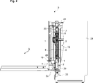
- Figure 2 – is a schematic cutaway side view of the dishwasher which has the coupling apparatus according to an embodiment of the present invention, wherein the door is in the fully opened state and the door-weight compensating apparatus is in the fully extended state;
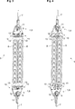
- Figure 3 – is a schematic perspective view of the door-weight compensating apparatus which has the coupling apparatus according to an embodiment of the present invention
- Figure 4 – is a schematic perspective view of the door-weight compensating apparatus which has the coupling apparatus according to an alternative embodiment of the present invention
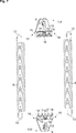
- Figure 5 shows schematic front views of the door-weight compensating apparatus of Fig. 3 in three different states
- Figure 6 shows schematic front views of the door-weight compensating apparatus of Fig. 4 in three different states
- Figure 7 – is a schematic perspective view of the coupling apparatus and the tension springs of Fig. 5, prior to the assembly;
- Figure 8 – is a schematic perspective view of the coupling apparatus and the tension springs of Fig. 6, prior to assembly;
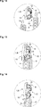
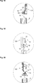
- Figure 9 – is a schematic enlarged front view of the coupling apparatus and the tension springs of Fig. 7 during the assembly;
- Figure 10 – is a schematic enlarged front view of the coupling apparatus and the tension springs of Fig.7, during the assembly;
- Figure 11 – is a schematic enlarged front view of the coupling apparatus and the tension springs of Fig.7, after the assembly;
- Figure 12 – is a schematic enlarged perspective view of the coupling apparatus and the tension springs of Fig. 9 during the assembly;
- Figure 13 – is a schematic enlarged perspective view of the coupling apparatus and the tension springs of Fig. 10, during the assembly;
- Figure 14 – is a schematic enlarged perspective view of the coupling apparatus and the tension springs of Fig. 11, after the assembly;
- Figure 15 – is a schematic enlarged perspective view of the coupling apparatus and the tension springs of Fig. 8, during the assembly;
- Figure 16 – is a schematic enlarged perspective view of the coupling apparatus and the tension springs of Fig. 8, during the assembly;
- Figure 17 – is a schematic enlarged perspective view of the coupling apparatus and the tension springs of Fig. 8, after the assembly;
- Figure 18 – is a schematic sectional view of the coupling apparatus and the tension springs of Fig. 11, taken along the line A-A;
- Figure 19 – is a schematic side view of the coupling apparatus and the tension springs of Fig. 11, when viewed from the direction B;
- Figure 20 – is a schematic sectional view of the coupling apparatus and the tension springs of Fig. 17, taken along the line C-C.
- the coupling apparatus (1) is suitable for use in a household appliance (2), in particular a dishwasher.
- the household appliance (2) comprises a door (3), a hinge (4) for pivotally supporting the door (3) about a horizontal axis and a door-weight compensating apparatus (5) for at least partly compensating for the weight of the door (3).
- the door-weight compensating apparatus (5) comprises one or more than one tension spring (6) for acting a tension force on the hinge (4) and two cables (7) for tensioning said one or more than one tension spring (6) respectively from both ends and for transmitting the tension force to the hinge (4).
- each tension spring (6) is stretched between the two cables (7) (Fig. 1 to 20).
- the coupling apparatus (1) of the present invention comprises two retainers (8) for parallely stretching said one or more than one tension spring (6) between the two cables (7).
- Each retainer (8) comprises a first attachment means (9) which is adapted to hold the end of the corresponding cable (7) and a second attachment means (10) which is adapted to hold the end of each corresponding tension spring (6).
- said one or more than one tension spring (6) are parallely stretched between the two cables (7) through the coupling apparatus (1).
- each first attachment means (9) comprises a hook (12) which is adapted to engage with the eye (11) of the corresponding cable (7).
- each second attachment means (10) also comprises one or more than one claw (15) which is respectively disposed adjacent to the corresponding saddle-shaped notch (14) for locking the hook (13) of the corresponding tension spring (6) in place.
- each retainer (8) comprises one or more than one reinforcement rib (16).
- each second attachment means (10) comprises one or more than one hole (17) for respectively receiving the end of the corresponding tension spring (6).
- each retainer (8) is adapted to stretch a single tension spring (6) between the two cables (7).
- each second attachment means (10) is adapted to hold the tension springs (6) side by side in an attachment position where the hooks (13) of the tension springs (6) bend towards each other (Fig. 3).
- each second attachment means (10) is adapted to hold the tension springs (6) side by side in an attachment position where the hooks (13) of the tension sprigs (13) bend away from each other (Fig. 4).
- the two retainers (8) of the coupling apparatus (1) are identical.
- the free end of the hinge (4) has a holder (19) which is adapted to engage with a mounting lug (20) which is fixed to the forward end of the cable (7) (Fig. 1 and 2).
- the door-weight compensating apparatus (5) comprises an adjusting device (21) for presetting the tension force.
- the rearward end of the cable (7) is fixed to the adjusting device (21).
- the door-weight compensating apparatus (5) comprises a roller (22) for deflecting the cable (7).
- the household appliance (2) comprises a duct (23) for slidably accommodating the door-weight compensating apparatus (5).
- the duct (23) extends in the vertical direction.
- the household appliance (2) is provided as a dishwasher (2).
- the dishwasher (2) has a tub (18).
- the door (3) is pivotally hinged about the horizontal axis for opening/closing the tub (18).
- the dishwasher (2) comprises side walls (24) and a frame (25) which supports the tub (18) and the side walls (24).
- the duct (23) is defined by the frame (25). The duct (23) is disposed between one of the side walls (24) and the tub (18).
- the household appliance (2) can be easily and reliably equipped with a comparatively heavier door (3) and furnished with a comparatively heavier decorative panel (3a). With the present invention, the customer satisfaction can be further increased.
Landscapes
- Washing And Drying Of Tableware (AREA)
Abstract
La présente invention concerne un appareil d'accouplement (1) destiné à être utilisé dans un appareil électroménager (2) comprenant une porte supportée à pivotement (3), une charnière (4) pour supporter la porte (3) et un appareil (5) de compensation du poids de la porte destiné à compenser au moins partiellement le poids de la porte (3). L'appareil d'accouplement (1) de la présente invention comprend deux éléments de retenue (8) servant à étirer en parallèle un ou plusieurs ressorts de tension (6) entre deux câbles (7) qui tendent lesdits un ou plusieurs ressorts de tension (6) respectivement à partir des deux extrémités et transmettent la force de tension à la charnière (4).
Priority Applications (1)
| Application Number | Priority Date | Filing Date | Title |
|---|---|---|---|
| PCT/EP2014/078258 WO2016095990A1 (fr) | 2014-12-17 | 2014-12-17 | Appareil d'accouplement destiné à être utilisé dans un appareil de compensation du poids de la porte d'un appareil électroménager |
Applications Claiming Priority (1)
| Application Number | Priority Date | Filing Date | Title |
|---|---|---|---|
| PCT/EP2014/078258 WO2016095990A1 (fr) | 2014-12-17 | 2014-12-17 | Appareil d'accouplement destiné à être utilisé dans un appareil de compensation du poids de la porte d'un appareil électroménager |
Publications (1)
| Publication Number | Publication Date |
|---|---|
| WO2016095990A1 true WO2016095990A1 (fr) | 2016-06-23 |
Family
ID=52146477
Family Applications (1)
| Application Number | Title | Priority Date | Filing Date |
|---|---|---|---|
| PCT/EP2014/078258 Ceased WO2016095990A1 (fr) | 2014-12-17 | 2014-12-17 | Appareil d'accouplement destiné à être utilisé dans un appareil de compensation du poids de la porte d'un appareil électroménager |
Country Status (1)
| Country | Link |
|---|---|
| WO (1) | WO2016095990A1 (fr) |
Cited By (3)
| Publication number | Priority date | Publication date | Assignee | Title |
|---|---|---|---|---|
| CN111706221A (zh) * | 2020-06-19 | 2020-09-25 | 珠海格力电器股份有限公司 | 一种门结构及家用电器 |
| US20250304259A1 (en) * | 2024-04-02 | 2025-10-02 | B/E Aerospace, Inc. | Linearly driven rotary actuator mechanism |
| WO2025232962A1 (fr) * | 2024-05-07 | 2025-11-13 | Electrolux Appliances Aktiebolag | Lave-vaisselle à porte à charnière |
Citations (5)
| Publication number | Priority date | Publication date | Assignee | Title |
|---|---|---|---|---|
| DE2424288A1 (de) * | 1973-05-25 | 1974-12-19 | Philips Nv | Federkonstruktion zum auswuchten der tuer einer geschirrspuelmaschine |
| DE9109818U1 (de) * | 1991-08-08 | 1992-09-10 | Licentia Patent-Verwaltungs-Gmbh, 6000 Frankfurt | Haushalt-Geschirrspülmaschine mit einer Türgewichtsausgleich-Verstellvorrichtung |
| WO2006137039A2 (fr) * | 2005-06-24 | 2006-12-28 | Arcelik Anonim Sirketi | Appareil domestique |
| DE102011076205A1 (de) * | 2011-05-20 | 2012-11-22 | BSH Bosch und Siemens Hausgeräte GmbH | Geschirrspülmaschine mit zumindest einer Federeinheit zur Beeinflussung einer geöffneten Tür |
| DE102011050914A1 (de) * | 2011-06-08 | 2012-12-13 | Miele & Cie. Kg | Geschirrspülmaschine |
-
2014
- 2014-12-17 WO PCT/EP2014/078258 patent/WO2016095990A1/fr not_active Ceased
Patent Citations (5)
| Publication number | Priority date | Publication date | Assignee | Title |
|---|---|---|---|---|
| DE2424288A1 (de) * | 1973-05-25 | 1974-12-19 | Philips Nv | Federkonstruktion zum auswuchten der tuer einer geschirrspuelmaschine |
| DE9109818U1 (de) * | 1991-08-08 | 1992-09-10 | Licentia Patent-Verwaltungs-Gmbh, 6000 Frankfurt | Haushalt-Geschirrspülmaschine mit einer Türgewichtsausgleich-Verstellvorrichtung |
| WO2006137039A2 (fr) * | 2005-06-24 | 2006-12-28 | Arcelik Anonim Sirketi | Appareil domestique |
| DE102011076205A1 (de) * | 2011-05-20 | 2012-11-22 | BSH Bosch und Siemens Hausgeräte GmbH | Geschirrspülmaschine mit zumindest einer Federeinheit zur Beeinflussung einer geöffneten Tür |
| DE102011050914A1 (de) * | 2011-06-08 | 2012-12-13 | Miele & Cie. Kg | Geschirrspülmaschine |
Cited By (4)
| Publication number | Priority date | Publication date | Assignee | Title |
|---|---|---|---|---|
| CN111706221A (zh) * | 2020-06-19 | 2020-09-25 | 珠海格力电器股份有限公司 | 一种门结构及家用电器 |
| CN111706221B (zh) * | 2020-06-19 | 2021-08-27 | 珠海格力电器股份有限公司 | 一种门结构及家用电器 |
| US20250304259A1 (en) * | 2024-04-02 | 2025-10-02 | B/E Aerospace, Inc. | Linearly driven rotary actuator mechanism |
| WO2025232962A1 (fr) * | 2024-05-07 | 2025-11-13 | Electrolux Appliances Aktiebolag | Lave-vaisselle à porte à charnière |
Similar Documents
| Publication | Publication Date | Title |
|---|---|---|
| EP2327824B1 (fr) | Machine à laver à tambour avec unités de charnière | |
| EP3339498B1 (fr) | Machine à laver | |
| US8857928B2 (en) | Appliance with a bracket for supporting a hinge | |
| US20150002005A1 (en) | Dishwasher | |
| JP6038907B2 (ja) | 引出し | |
| US20150150432A1 (en) | Domestic appliance having a locking arrangement and a door-weight-compensation system | |
| EP1903136A1 (fr) | Machine à laver | |
| WO2016095990A1 (fr) | Appareil d'accouplement destiné à être utilisé dans un appareil de compensation du poids de la porte d'un appareil électroménager | |
| WO2009075523A1 (fr) | Réfrigérateur | |
| EP3670727B1 (fr) | Structure de couplage pour des appareils de traitement du linge | |
| US9055857B2 (en) | Domestic appliance with a door-weight compensating device | |
| CA2746104C (fr) | Appareil electromenager comprenant un panneau decoratif coulissant sur sa porte | |
| EP1529482B1 (fr) | Appareil électroménager encastré avec panneau d' habillage appliqué sur la porte | |
| CN101677745B (zh) | 用于洗碗机的台下安装系统及相关方法 | |
| EP3312328A1 (fr) | Machine à laver comportant des agencements de lavage distincts | |
| EP1875850A1 (fr) | Appareil ménager encastré avec panneau décoratif appliqué sur la porte | |
| US20130214660A1 (en) | Hinge for an appliance | |
| KR20190128421A (ko) | 냉장고 | |
| WO2016086965A1 (fr) | Lave-vaisselle comprenant un appareil de compensation du poids de la porte | |
| EP1364609B1 (fr) | Appareil électroménager à encastrer avec avant-plaque appliquée sur la porte | |
| US20190261829A1 (en) | Domestic dishwasher | |
| EP2672186A1 (fr) | Four pour cuire des produits alimentaires | |
| CN114098585B (zh) | 用于洗碗设备的轮架 | |
| US11885059B2 (en) | Suspension system | |
| EP2164365B1 (fr) | Poignée pour un appareil électroménager |
Legal Events
| Date | Code | Title | Description |
|---|---|---|---|
| 121 | Ep: the epo has been informed by wipo that ep was designated in this application |
Ref document number: 14818954 Country of ref document: EP Kind code of ref document: A1 |
|
| NENP | Non-entry into the national phase |
Ref country code: DE |
|
| 122 | Ep: pct application non-entry in european phase |
Ref document number: 14818954 Country of ref document: EP Kind code of ref document: A1 |