WO2016098144A1 - Vérin à air de faible densité - Google Patents
Vérin à air de faible densité Download PDFInfo
- Publication number
- WO2016098144A1 WO2016098144A1 PCT/JP2014/006333 JP2014006333W WO2016098144A1 WO 2016098144 A1 WO2016098144 A1 WO 2016098144A1 JP 2014006333 W JP2014006333 W JP 2014006333W WO 2016098144 A1 WO2016098144 A1 WO 2016098144A1
- Authority
- WO
- WIPO (PCT)
- Prior art keywords
- hose
- airtight
- air supply
- airtight body
- supply hose
- Prior art date
- Legal status (The legal status is an assumption and is not a legal conclusion. Google has not performed a legal analysis and makes no representation as to the accuracy of the status listed.)
- Ceased
Links
Images


Classifications
-
- B—PERFORMING OPERATIONS; TRANSPORTING
- B66—HOISTING; LIFTING; HAULING
- B66F—HOISTING, LIFTING, HAULING OR PUSHING, NOT OTHERWISE PROVIDED FOR, e.g. DEVICES WHICH APPLY A LIFTING OR PUSHING FORCE DIRECTLY TO THE SURFACE OF A LOAD
- B66F3/00—Devices, e.g. jacks, adapted for uninterrupted lifting of loads
- B66F3/24—Devices, e.g. jacks, adapted for uninterrupted lifting of loads fluid-pressure operated
- B66F3/247—Devices, e.g. jacks, adapted for uninterrupted lifting of loads fluid-pressure operated pneumatically actuated
-
- B—PERFORMING OPERATIONS; TRANSPORTING
- B66—HOISTING; LIFTING; HAULING
- B66F—HOISTING, LIFTING, HAULING OR PUSHING, NOT OTHERWISE PROVIDED FOR, e.g. DEVICES WHICH APPLY A LIFTING OR PUSHING FORCE DIRECTLY TO THE SURFACE OF A LOAD
- B66F3/00—Devices, e.g. jacks, adapted for uninterrupted lifting of loads
- B66F3/24—Devices, e.g. jacks, adapted for uninterrupted lifting of loads fluid-pressure operated
- B66F3/25—Constructional features
- B66F3/35—Inflatable flexible elements, e.g. bellows
-
- B—PERFORMING OPERATIONS; TRANSPORTING
- B66—HOISTING; LIFTING; HAULING
- B66F—HOISTING, LIFTING, HAULING OR PUSHING, NOT OTHERWISE PROVIDED FOR, e.g. DEVICES WHICH APPLY A LIFTING OR PUSHING FORCE DIRECTLY TO THE SURFACE OF A LOAD
- B66F2700/00—Lifting apparatus
- B66F2700/05—Hydraulic jacks
Definitions
- the present invention for example, lifts heavy objects such as automobiles that are repaired or inspected, or rescues a person who is underlayed by lifting a required part such as a building collapsed due to an earthquake, typhoon, accident, etc. It is related to a thin-type air jack that is used for carrying out, especially with excellent safety, can be inserted even in extremely narrow gaps and can lift heavy objects such as automobiles, and also supplies air even in bicycle air pumps and compressors The present invention relates to a thin air jack that is excellent in handling and operability.
- hydraulic jacks mechanical jacks, and the like have been used for jacks that lift heavy objects such as automobiles.
- Each of these jacks has a problem that it has a high height when shrunk, cannot be inserted into a narrow gap, and is heavy and inferior in handleability.
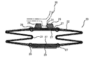
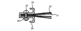
- the air jack device 20 includes a rectangular rubber tube 21 and a rectangular body made of nylon woven fabric or aramid woven fabric. And an air joint 23 for supplying air to the rubber tube 21, and a pair of opposing sides of the rubber tube 21 and the outer enclosure 22 are sandwiched between a metal plate 24, a screw 25, and a nut 26, respectively. At the same time, the opposite sides of the rubber tube 21 and the outer envelope 22 are folded inward in a V shape.
- two sets of metal reinforcing plates 27 are arranged between the rubber tube 21 and the outer envelope 22 and on the surface of the outer envelope 22 with the outer envelope 22 interposed therebetween.
- the two sets of metal reinforcing plates 27 are connected by rivets 28.
- a rubber plate 29 is fixed to each of the metal reinforcing plates 27 on the surface side of the outer enclosure 22, and the lower frame 30 of the automobile body is attached to the upper rubber plate 29 of the rubber plates 29.
- a recessed groove 31 is formed.
- the air jack device 20 is arranged on the lower surface of the heavy object to be lifted, when the compressed air is injected into the rubber tube 21 from the air joint 23, the rubber tube 21 expands and accompanying this.
- the outer envelope 22 also expands and can lift a heavy object.
- this air jack device 20 uses a rubber tube 21 and a woven fabric outer envelope 22, the overall appearance can be thinned and a heavy object can be lifted by being inserted into a narrow gap. .
- the air jack device 20 contains the rubber tube 21 in the outer envelope 22 made of woven fabric, the friction resistance between the outer envelope 22 and the rubber tube 21 becomes extremely large.
- the rubber tube 21 swells in a state where a load is applied to the rubber tube 21, the rubber tube 21 does not swell evenly, and there is a possibility that the rubber tube 21 may burst due to a partial heavy load on the rubber tube 21, There was a problem that it was inferior in safety.
- the compressed air may be excessively injected into the rubber tube 21, and in the worst case, the rubber tube 21 may be ruptured.
- the air jack device 20 holds both ends of the rubber tube 21 and the outer enclosure 22 between the metal plates 24, and attaches a metal reinforcing plate 27 and a rubber plate 29 to the center surface of the outer enclosure 22. Therefore, the thickness cannot be extremely reduced, and the minimum thickness is about 6 cm. As a result, there is a problem that it cannot be inserted into a very narrow gap and cannot be used.
- the air jack device 20 since the air jack device 20 has to inflate the rubber tube 21, for example, it is difficult to inflate the rubber tube 21 when manually inflating a bicycle, and an air compressor is required for use, which improves handling and operability. There was a problem of being inferior.
- An object of the present invention is to provide a thin air jack that is capable of supplying air even with a bicycle inflator or a compressor and has excellent handling and operability.
- the first invention of the present invention includes an airtight body formed in a bag shape having a sealed structure with a film, a base end portion being airtightly attached to the airtight body, and a distal end Air supply hose provided with a check valve-connected connector connected to the air supply source at the part, and a valve mounting hose with the base end part being airtightly attached to the airtight body and a safety valve provided at the tip part
- a cover body that is formed into a bag shape with a synthetic resin material having a low frictional resistance, and that accommodates the airtight body in a state in which the tips of the air supply hose and the valve mounting hose protrude outward, respectively, and a synthetic fiber weave
- An interior body that is formed into a bag shape with cloth and accommodates the airtight body and cover body with the air supply hose and valve mounting hose protruding outward, and a hose with the same structure as the fire hose are turned over.
- the airtight body is formed in a rectangular bag shape having a sealed structure with a multilayer film or a single layer film excellent in gas barrier properties
- the air supply hose and the valve mounting hose are provided with a sloped hose mounting cylinder portion into which the base end portions of the air supply hose and the valve mounting hose are inserted, respectively. It is inserted in the attachment cylinder part, respectively, and a part or all of the outer peripheral surface of the hose attachment cylinder part is characterized by being tightened in an airtight manner by a fastening means and being prevented from coming off.
- the third invention of the present invention is characterized in that, in the second invention, the multilayer film is a nylon multilayer film, and the single-layer film is a thermoplastic polyurethane film.
- each hose mounting cylinder portion of the airtight body and a base end portion of the air supply hose and the valve mounting hose are located inward of the airtight body.
- the supply hose and the tip of the valve mounting hose are characterized in that they are located outward of the airtight body.
- the fifth invention of the present invention is characterized in that, in the second invention, the other two sides which are not provided with the airtight hose attachment tube are folded inward.
- the invention according to a sixth aspect of the present invention is characterized in that, in the second invention, the insertion lengths of the air supply hose and the valve mounting hose into the hose mounting cylindrical portion of the airtight body are each several cm or more. is there.
- an adhesive layer is interposed between the outer peripheral surface of the base end of the air supply hose and the valve mounting hose and the inner peripheral surface of the airtight hose mounting cylinder.
- the eighth invention of the present invention is characterized in that, in the first invention, a reinforcing piece made of tape, cloth or resin sheet is attached to a part or all of both surfaces of the outer peripheral edge of the hermetic body. .
- the ninth invention of the present invention is characterized in that, in the first invention, the one-touch joint coupler with a check valve is used as the connection tool with a check valve provided in the air supply hose.
- the cover body is formed in a rectangular bag shape having at least one side opened by a synthetic resin tube or a synthetic resin sheet, It is characterized in that a lead-out hole is formed in the adjacent side so that the leading end side of the air supply hose and the valve mounting hose can be pulled out to the outside.
- the interior body is made of a synthetic woven belt-like woven fabric, and both ends of the belt-like woven fabric are overlapped and the overlapping portion is sewn or sewn.
- the airtight body and the cover body are accommodated inside the interior body, and both ends of the airtight body are held on the inner surface of the interior body.
- the exterior body is made of a thermoplastic polyurethane elastomer on an inner peripheral surface of a jacket in which a synthetic fiber warp and a synthetic fiber weft are woven in a cylindrical shape.
- the hose with the same structure as the fire hose with the lining layer is turned upside down or the cylindrical fabric is coated, and the leading end of the air supply hose and valve mounting hose is open from the base end opening of the exterior body It is characterized in that it is formed in a flat bag shape by closing the opening at both ends of the fire hose or cylindrical fabric with at least one of metal fittings, welding and sewing in a state of protruding outward.
- the thirteenth invention of the present invention is characterized in that, in the first invention, a part of the air supply hose and a part of the exterior body are fixed by caulking with a metal ring.
- the thin air jack of the present invention accommodates a bag-like airtight body formed of a film in a bag-like cover body formed of a synthetic resin material, and further has the same structure as the synthetic fiber interior body and the fire hose. Since the outer casing or the cylindrical outer casing coated with a cylindrical fabric is sequentially accommodated, the cover body greatly reduces the frictional resistance between the hermetic body and the inner casing. When the airtight body inflates with the load applied to the air jack, the airtight body swells evenly, and there is no partial load on the airtight body, preventing the airtight body from bursting and safety Is excellent.
- the thin air jack of the present invention has a valve mounting hose provided with a safety valve on the airtight body, so that when the airtight body is inflated, excessive compressed air is discharged from the safety valve even if excessive air is put into the airtight body. Therefore, the airtight body does not rupture, and the safety is better.
- the airtight body is formed of a multilayer film or a single layer film having excellent gas barrier properties, the airtightness of the airtight body is extremely excellent. Since the hose with the same structure as that of the inside or the coated cylindrical fabric is used, the durability and burst resistance of the exterior body will be greatly improved, and air will escape during use. And the exterior body does not rupture, which is superior in safety.
- the thin air jack of the present invention comprises a bag-like airtight body, a bag-like cover body, a bag-like interior body, and a cylindrical exterior body, when these are flattened, the thickness thereof should be extremely thin. As a result, even a very narrow gap can be inserted and a heavy object such as an automobile can be lifted.
- the thin air jack of the present invention forms a hose attachment cylinder portion into which the base end portions of the air supply hose and the valve attachment hose are respectively inserted on opposite sides of a sealing body formed in a rectangular bag shape, and each hose attachment Insert the base end of the air supply hose and the valve mounting hose into the cylinder part and tighten part or all of the outer peripheral surface of each hose mounting cylinder part with the fastening means to prevent the air supply hose and valve mounting hose from coming off. Therefore, the strength of the airtight body can be maintained as compared with the case where a hole for inserting the air supply hose and valve mounting hose is opened in the airtight body, and the air supply hose and valve mounting hose are separated from the airtight body. In addition to being difficult to remove, the airtightness between the hose mounting cylinder and the air supply hose and valve mounting hose is improved, and the airtightness The air is less likely to come out.
- the thin air jack of the present invention is provided with a connector with a check valve at the tip of an air supply hose that supplies air to an airtight body, and this connector with a check valve is a one-touch joint type coupler with a check valve. Therefore, by changing the medium hose, air can be supplied even with a manual bicycle inflator or a compressor or a foot pump, which is excellent in handling and operability.
- each hose attachment cylinder portion for attaching the base end portion of the air supply hose and the valve attachment hose is located inside the airtight body. Without receiving external force, it is possible to prevent each hose attachment tube portion of the airtight body from being broken.
- the thin air jack of the present invention has two sides that are not provided with an airtight hose attachment portion folded inward, so that even if the airtight body expands, the two sides may be forcibly stretched. In addition, it is possible to prevent the both end portions (two sides not provided with the hose attachment cylinder portion) from being broken.
- the air supply hose and valve mounting hose is strongly pressed against the inner peripheral surface side of the exterior body by the internal pressure of the airtight body.
- the air supply hose is not required to be stronger than necessary.
- the insertion length of the air supply hose and the valve mounting hose into the hose mounting cylinder is several centimeters or more, so that the air supply hose and the valve mounting hose are more easily removed from the airtight body. It becomes difficult.
- an adhesive layer is interposed between the outer peripheral surface of the base end portion of the air supply hose and the valve mounting hose and the inner peripheral surface of the hose mounting cylinder portion of the airtight body.
- the mounting hose is more difficult to remove from the airtight body, and the airtightness between the hose mounting cylinder, the air supply hose and the valve mounting hose is further enhanced, and air is more difficult to escape from the airtight body.
- a reinforcing piece made of tape, cloth, or resin sheet is attached to a part or all of both surfaces of the outer peripheral edge of the airtight body, so a part or all of the outer peripheral edge of the airtight body Even if the compressed air is injected into the airtight body, the outer peripheral edge of the airtight body is hardly broken.
- the interior body is composed of a strip-shaped woven fabric made of synthetic fiber, and both end portions of the strip-shaped woven fabric are overlapped and the overlapping portion is sewn or adhered, and the interior of the interior body is inward. Since the airtight body and the cover body are stored and both ends of the airtight body are held on the inner surface of the interior body, both ends of the airtight body are held by the interior body when the airtight body swells. Both ends of the body are difficult to tear.
- the thin air jack of the present invention uses an exterior body with a hose having the same structure as the fire hose turned over or a cylindrical fabric coated, the abrasion resistance and weather resistance of the exterior body, etc. And the strength of the exterior body can be improved.
- a part of the air supply hose and a part of the exterior body are fixed by caulking with a metal ring, so that the air supply hose is more difficult to come off.
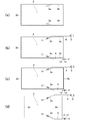
- FIG. 1 It is a top view of the thin air jack concerning the embodiment of the present invention. It is a disassembled perspective view of a thin air jack. It is explanatory drawing which shows the attachment state of the air supply hose and valve attachment hose to an airtight body, (a) is a top view of the airtight body before attaching an air supply hose and a valve attachment hose, (b) is a hose of an airtight body The top view which attached the base end part of the air supply hose and the valve mounting hose to the attachment cylinder part, (c) is the top view which welded the opening of an airtight body, (d) folded the both ends of an airtight body inside It is a top view of a state.
- FIG. 11 is an enlarged sectional view taken along the line CC of FIG. 10.
- FIG. 1 and 2 show a thin air jack 1 according to an embodiment of the present invention.
- the thin air jack 1 lifts an automobile when repairing or inspecting an automobile such as a normal automobile or a special automobile, Alternatively, it is used to rescue a person who is underlaying by lifting a necessary part such as a building collapsed by an earthquake or a typhoon.
- the thin air jack 1 includes an airtight body 2 formed into a rectangular bag shape having a sealed structure with a film, and a base end portion that is airtightly attached to the airtight body 2 and an air supply source at the distal end portion.
- An air supply hose 4 provided with a connection tool 3 with a check valve connected to the valve, a valve mounting hose 6 having a base end portion inserted into the airtight body 2 in an airtight manner and a safety valve 5 provided at the distal end portion,
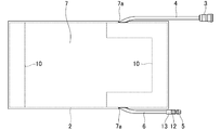
- a cover body 7 which is formed into a rectangular bag shape with a synthetic resin material having a low frictional resistance, and accommodates the airtight body 2 in a state where the leading ends of the air supply hose 4 and the valve mounting hose 6 respectively protrude outward.
- An interior body 8 which is formed in a rectangular bag shape by a woven fabric made of synthetic fiber and accommodates the airtight body 2 and the cover body 7 with the air supply hose 4 and the tip of the valve mounting hose 6 projecting outward.
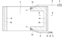
- the airtight body 2 is formed by superposing two film materials formed in a rectangular shape with a multilayer film or a single layer film excellent in gas barrier properties, and one of the two film materials. Except for the short side, the outer peripheral edges of the two film materials are welded 2b (thermal welding, ultrasonic welding, or high frequency welding) over a width of several mm, and are formed in a rectangular bag shape, facing each other. On the long side, there is provided a hose attachment tube portion 2a in an inclined posture into which the base ends of the air supply hose 4 and the valve attachment hose 6 are respectively inserted.
- the multilayer film or single layer film excellent in gas barrier property refers to a multilayer film or single layer film having an oxygen permeability of 40 cc / m 2 ⁇ atm ⁇ day or less and a moisture permeability of 8 g / m 2 ⁇ day or less.
- the airtight body 2 is formed in such a manner that the base ends of the air supply hose 4 and the valve mounting hose 6 are inserted into the respective hose mounting cylinders 2a of the airtight body 2, respectively.
- the open side (short side) of the hermetic body 2 is closed by welding 2b (thermal welding, ultrasonic welding, or high frequency welding) to form a rectangular bag with a sealed structure. .
- the two sides (short sides) of the airtight body 2 where the air supply hose 4 and the valve mounting hose 6 are not attached are V-shaped inward of the airtight body 2 as shown in FIGS. (The portion located inside the airtight body 2 has a V-shaped cross section), and even if the airtight body 2 expands, the two sides (short sides) are forcibly stretched. I am trying not to. Thereby, it can prevent that the both ends (two sides which are not provided with the hose attachment cylinder part 2a) of the airtight body 2 are torn.
- the two sides (short sides) of the hermetic body 2 are not shown in the figure, but are W-shaped inwardly of the hermetic body 2 (the portion located inside the hermetic body 2 has a W-shaped cross-section). )).
- FIGS. the outer surfaces of both ends on the short side of the hermetic body 2 and the outer surfaces of both ends on the long side of the hermetic body 2 that are opposed to the air supply hose 4 and the valve mounting hose 6 are shown in FIGS.
- a reinforcing piece 10 made of duct tape is affixed to reinforce a part of the outer peripheral edge of the airtight body 2.
- the airtight body 2 is made of a flexible three-layer film having excellent gas barrier properties, that is, triple nylon (trade name) manufactured by MICS Chemical Co., Ltd. It is formed by welding 2b of two rectangular film materials by impulse welding.
- This triple nylon has a thickness of 70 ⁇ m, a tensile strength of 45 MPa, a tensile elongation of 350%, a tear strength of 140 N / mm, an impact strength of 140 N ⁇ cm, a puncture strength of 5.0 N, and an oxygen permeability of 40 cc / m 2.
- -Atm * day and water vapor transmission rate are 8g / m ⁇ 2 > * day.
- the length of the hermetic body 2 is about 56 cm
- the width of the hermetic body 2 is about 28 cm
- the width of the welded portion of the hermetic body 2 is 5 mm
- each hose attachment cylinder portion of the hermetic body 2 The length of 2a is set to about 5 cm to 10 cm, respectively.
- the hermetic body 2 is formed of a three-layer film.
- the hermetic body 2 is formed of a polyester such as a thermoplastic polyurethane film, a polylactic acid film, or a PET / PEN / PBT film. It may be formed by a single layer film such as a film, a barrier resin film such as EVOH / PVA / barrier Ny, or the airtight body 2 is a four-layer film (for example, Diamilon M-G708 (trade name)), 5 A layer film (for example, film mix HB (trade name) or five barrier (trade name)) may be used.
- the reinforcing piece 10 is attached to a part of both surfaces of the outer peripheral edge of the airtight body 2.
- all the outer peripheral edge of the airtight body 2 is reinforced.
- the piece 10 may be pasted.
- the reinforcing piece 10 made from a duct tape was affixed on the airtight body 2
- the airtight body 2 is made of aluminum tape, cloth adhesive tape or gum tape.
- the reinforcing piece 10 may be attached, or the reinforcing piece 10 made of cloth or the reinforcing piece 10 made of a synthetic resin sheet may be attached to the airtight body 2 with a double-sided adhesive tape or an adhesive.
- the air supply hose 4 is formed of a pressure-resistant hose made of a special polyurethane resin, and a base end portion of the air supply hose 4 is inserted into one hose attachment cylinder portion 2a of the airtight body 2, and the outer peripheral surface of the hose attachment cylinder portion 2a. While being partly or entirely tightened with a tightening means, it is prevented from coming off, and at its tip part, a connecting tool 3 with a check valve connected to an air supply source (not shown) is provided.
- a thread 11 (polyester thread) is used as the fastening means. That is, the base end portion of the air supply hose 4 is inserted into the one hose attachment tube portion 2a from the outside of the airtight body 2 as shown in FIG.
- the thread 11 (polyester thread) is tightly wound around a part (or all) of the outer peripheral surface of the cylindrical part 2a to prevent the cylinder part 2a from coming off.
- an adhesive layer (not shown) is interposed between the outer peripheral surface of the base end portion of the air supply hose 4 and the inner peripheral surface of the hose attachment cylinder portion 2a of the airtight body 2. The end portion is prevented from coming off from the hose attachment tube portion 2a, and the airtightness between the outer peripheral surface of the base end portion of the air supply hose 4 and the inner periphery surface of the hose attachment tube portion 2a of the airtight body 2 is maintained. I am doing so.
- the air supply hose 4 is inserted into the hose attachment cylinder 2a so that the insertion length of the airtight body 2 into the hose attachment cylinder 2a is several cm or more, preferably 3 cm or more. Is set so as not to be easily removed from the airtight body 2.
- the insertion length of the air supply hose 4 into the hose attachment cylinder 2a is set to be substantially the same as the length of the hose attachment cylinder 2a.
- the connector 3 with a check valve provided at the tip of the air supply hose 4 is a socket type and one-touch joint type coupler with a check valve, and is used as an air supply source for a bicycle, a compressor or a stepping type.
- the pump can be connected to the pump via a medium hose (both not shown) with one touch.
- the connector 3 with check valve is a socket type and one-touch joint type coupler with check valve.
- the connector 3 with check valve is plugged. It is also possible to use a one-touch joint type coupler with a check valve.
- the valve mounting hose 6 is formed of a pressure-resistant hose made of a special polyurethane resin, and a base end portion of the valve mounting hose 6 is inserted into the other hose mounting cylindrical portion 2a of the airtight body 2, and the outer peripheral surface of the hose mounting cylindrical portion 2a is A part or the whole is fastened by fastening with a fastening means, and a safety valve 5 is attached to the tip of the tip through a hose nipple 12 by caulking with a metal ring 13 (aluminum ring).
- a thread 11 (polyester thread) is used as the fastening means. That is, the base end portion of the valve mounting hose 6 is inserted into the other hose mounting tube portion 2a from the outside of the airtight body 2 and is located inside the airtight body 2 as shown in FIG.
- the thread 11 (polyester thread) is tightly wound around a part (or all) of the outer peripheral surface of the mounting cylinder portion 2a to prevent it from coming off.
- an adhesive layer (not shown) is interposed between the outer peripheral surface of the base end portion of the valve mounting hose 6 and the inner peripheral surface of the hose mounting cylinder portion 2a of the airtight body 2. The end portion is prevented from coming off from the hose attachment tube portion 2a, and the airtightness between the outer peripheral surface of the base end portion of the valve attachment hose 6 and the inner periphery surface of the hose attachment tube portion 2a of the airtight body 2 is maintained. I am doing so.
- valve mounting hose 6 is inserted into the hose mounting cylinder 2a so that the insertion length of the airtight body 2 into the hose mounting cylinder 2a is several cm or more, preferably 3 cm or more. Is set so as not to be easily removed from the airtight body 2.
- the insertion length of the valve mounting hose 6 into the hose mounting cylinder 2a is set to be substantially the same as the length of the hose mounting cylinder 2a.
- the safety valve 5 provided at the distal end of the valve mounting hose 6 is configured so that the air in the airtight body 2 is increased when the pressure in the airtight body 2 becomes 0.1 MPa higher than the maximum operating pressure (0.7 MPa) due to excessive supply of air. Is automatically released to return the pressure in the airtight body 2 to a predetermined pressure, thereby preventing the airtight body 2 from bursting.
- the set pressure of the safety valve 5 is 0.8 MPa.
- the thread 11 is used as the tightening means, and the thread 11 is tightly wound around the outer peripheral surface of each hose mounting cylinder portion 2a of the airtight body 2 to connect the air supply hose 4 and the valve mounting hose 6 to each other.
- a metal ring (not shown) or a heat-shrinkable tube (not shown) may be used as the tightening means. That is, each hose attachment cylinder part 2a into which the air supply hose 4 and the valve attachment hose 6 are respectively inserted is caulked by a metal ring (not shown), and the air supply hose 4 and the valve attachment hose 6 are removed from each hose attachment cylinder part 2a.
- the air supply hose 4 and the valve mounting hose 4 and the valve mounting hose 6 may be inserted into the hose mounting cylinder 2a by tightening and fixing with a heat shrinkable tube (not shown).
- the hose 6 may be prevented from coming off from each hose attachment cylinder portion 2a.
- the cover body 7 is formed in a rectangular bag shape having one end or both ends opened by a synthetic resin tube (polyethylene tube) having a low frictional resistance, and an open side (short side).
- the side (long side) adjacent to the side) is formed with a lead-out hole 7a through which the leading ends of the air supply hose 4 and the valve mounting hose 6 can be pulled out to the outside.
- the cover body 7 is formed in a size that can completely accommodate the airtight body 2.
- the synthetic resin having a low frictional resistance means a synthetic resin having a static friction coefficient of 0.1 to 0.3 and a dynamic friction coefficient of 0.04 to 0.3.
- the cover body 7 is formed of a polyethylene tube.
- the cover body 7 may be formed in a bag shape using a polyethylene sheet, or the cover body 7 may be made of fluorine. You may form with a synthetic resin tube or a synthetic resin sheet with little frictional resistance, such as resin.
- the cover body 7 may be formed of a Teflon sheet.
- the interior body 8 is made of an aramid fiber strip-like woven fabric that has excellent strength and wear resistance and little stretch, and overlaps both ends of the strip-like woven fabric. Is formed into a ring shape and a rectangular planar shape.
- the airtight body 2 and the cover body 7 are accommodated in the interior body 8, and both end portions of the airtight body 2 are held by the inner surfaces of the folded portions at both ends of the interior body 8.
- both sides of both ends in the longitudinal direction of the interior body 8 are attached by an appropriate length 8b so that the stored airtight body 2 and the cover body 7 do not protrude outward from the side edges of the interior body 8. .
- the interior body 8 is formed from an aramid fiber woven fabric.
- the interior body 8 is formed from a polyester fiber woven fabric or a polypropylene fiber woven fabric.
- the belt-like woven fabric is sewn 8a to form the interior body 8, but in other embodiments, the belt-like woven fabric is bonded with an adhesive to form the interior body 8. You may make it do.
- the exterior body 9 is formed of a thermoplastic polyurethane elastomer lining layer on the inner peripheral surface of a jacket in which a synthetic fiber warp and a synthetic fiber weft are woven in a cylindrical shape.
- the fire hose is formed by a hose having the same structure as the fire hose, and the hose is turned over so that the lining layer faces outward.
- This hose uses a fire hose type test (type test conducted by the Japan Fire Service Certification Association) in terms of structure, properties of synthetic resin, adhesion strength, function, wear resistance, and the like. Polyester filament yarn, aramid filament yarn, or the like is used for the warp yarn and weft yarn made of synthetic fiber.
- the exterior body 9 accommodates the airtight body 2, the cover body 7, and the interior body 8 in a state where the leading ends of the air supply hose 4 and the valve mounting hose 6 protrude outward from one end opening of the exterior body 9.
- the part opening is closed by a plurality of metal fittings 14 (eyelet metal fittings) and ultrasonic welding 9a to form a flat bag shape, which is large enough to accommodate the airtight body 2, the cover body 7 and the interior body 8. Is set.
- the exterior body 9 has a lining layer made of thermoplastic polyurethane elastomer formed on the outer surface thereof, so it has extremely high wear resistance, high mechanical strength, and elasticity at a wide range of operating temperatures. Furthermore, there is an advantage that the impact strength is strong, it is strong against low-temperature bending, and the oil resistance, chemical resistance, bacteria resistance and the like are good.
- annular center mark 15 indicating the center position of the thin air jack 1 and a caution mark 16 describing the precautions of the thin air jack 1 are provided.
- the lining layer is formed of a thermoplastic polyurethane elastomer.
- the lining layer may be formed of another synthetic resin, for example, PET (polyethylene terephthalate).
- the exterior body 9 is used by turning the hose having the same structure as the fire hose upside down.
- the exterior body 9 has a strong cylindrical woven fabric. You may make it use what gave the painting.
- a cylindrical woven fabric made of polyester canvas is used as a strong cylindrical woven fabric, and urethane resin, acrylic resin, silicon resin, fluorine resin, or the like is used for coating.
- both end portions of the exterior body 9 are closed by ultrasonic welding with the metal fitting 14, but in other embodiments, both end portions of the exterior body 9 are attached by the metal fitting 14 and sewing 9a. You may make it close, or you may make it close the both ends of the exterior body 9 only by welding 9a or adhesion.
- the base ends of the air supply hose 4 and the valve mounting hose 6 are inserted into the respective hose mounting cylinders 2a of the airtight body 2 whose one short side is open, and the respective hoses located inside the airtight body 2 are inserted.
- the thread 11 is tightly wound around a part of the outer peripheral surface of the attachment cylinder portion 2a, and an adhesive is applied (see FIGS. 3A and 3B).
- an adhesive layer is interposed between the outer peripheral surfaces of the base end portions of the air supply hose 4 and the valve catching hose and the inner peripheral surface of each hose attachment cylinder portion 2a.
- the air supply hose 4 and the valve attachment hose 6 are attached to the hose attachment cylinder part 2a of the airtight body 2 in an airtight manner.
- both ends on the short side of the airtight body 2 are folded inside, and the outer surfaces of both ends on the short side of the airtight body 2 are opposed to the air supply hose 4 and the valve mounting hose 6.
- a reinforcing piece 10 made of duct tape is affixed to the outer surface of both ends of the long side of the hermetic body 2 (see FIGS. 3D and 4).
- the airtight body 2 When the reinforcing piece 10 is attached to the airtight body 2, the airtight body 2 is accommodated in the cover body 7, and the leading ends of the air supply hose 4 and the valve mounting hose 6 are respectively connected to the cover body 7 from the respective drawing holes 7 a of the cover body 7. Pull out outward (see FIG. 6).
- the airtight body 2 When the airtight body 2 is accommodated in the cover body 7, the airtight body 2 and the cover body 7 are accommodated in the interior body 8, and the leading ends of the air supply hose 4 and the valve mounting hose 6 are drawn out of the interior body 8. (See FIG. 7).
- the interior body 8 that houses the airtight body 2 and the cover body 7 is housed in the cylindrical exterior body 9, and the distal end portion of the air supply hose 4, the connector 3 with a check valve, and the distal end of the valve mounting hose 6.
- the safety valve 5 provided in the outer portion protrudes outward from one end opening of the exterior body 9, both ends of the exterior body 9 are closed by a plurality of metal fittings 14 (eyelet metal fittings) and welds 9 a, and a part of the air supply hose 4 And a part of the exterior body 9 are fixed by caulking with a metal ring 13 (see FIG. 8).
- the thin air jack 1 thus manufactured has a length of about 60 cm, a width of about 24 cm, and a thickness of about 6 mm (excluding the air supply hose 4, the valve mounting hose 6, the connector 3 with a check valve and the safety valve 5). It can be lifted up to a maximum weight of about 9,400 kg.
- the thin air jack 1 has a pressure resistance of 2.1 MPa, a use temperature range of ⁇ 20 ° C. to 80 ° C., and a mass of 1170 g per meter.
- the manufacturing method of the thin air jack 1 is not limitedly interpreted to said embodiment, A various change is possible.
- the thin air jack 1 described above can provide the following excellent effects. (1) Since the thin air jack 1 covers the bag-shaped airtight body 2 formed of a film with the bag-shaped cover body 7 formed of a synthetic resin material having a low frictional resistance, the cover body 7 The frictional resistance with the interior body 8 is greatly reduced. As a result, when the airtight body 2 swells in a state where a load is applied to the thin air jack 1, the airtight body 2 swells evenly. The load is not partially applied, and the airtight body 2 can be prevented from rupturing, which is excellent in safety.
- the thin air jack 1 Since the thin air jack 1 is provided with the valve mounting hose 6 provided with the safety valve 5 on the hermetic body 2, the safety valve 5 can be used even if excessive air is introduced into the hermetic body 2 when the hermetic body 2 is inflated. Since excess air is discharged from the airtight body 2, the airtight body 2 does not rupture, and the safety is further improved.
- the thin air jack 1 has excellent airtightness of the airtight body 2 and excellent durability and rupture resistance of the exterior body 9. In addition, the exterior body 9 does not rupture, and the safety is extremely excellent.
- the thin air jack 1 is composed of an airtight body 2 made of a film, a cover body 7 made of a synthetic resin tube, an interior body 8 made of a synthetic fiber, an exterior body 9 having the same structure as a fire hose, and the like. When it is flattened, its thickness becomes extremely thin and can be inserted even in a very narrow gap.
- the thin air jack 1 is provided with a check valve coupler at the tip of the air supply hose 4, so by changing the medium hose, air can be supplied to a manual bicycle pump or a compressor or foot pump. Can be supplied and is excellent in handling and operability.
- both ends of the hermetic body 2 will not be forcibly stretched even if the hermetic body 2 expands, and both ends of the sealed body will be broken. Can be prevented.
- the thin air jack 1 inserts the base ends of the air supply hose 4 and the valve mounting hose 6 into two cylindrical hose mounting cylinders 2a formed in the airtight body 2, and each hose mounting cylinder 2a Since the thread 11 is tightly wound around the outer peripheral surface of the airtight body 2, the strength of the airtight body 2 can be maintained as compared with the case where a hole for inserting the air supply hose 4 is formed in the airtight body 2, and the air supply hose 4 and the valve mounting hose 6 are not easily removed from the airtight body 2, and the airtightness between the hose holding cylinder portion and the air supply hose 4 is enhanced so that the air is difficult to escape.
- FIG. 1 As shown in FIG.
- the thin air jack 1 is configured such that when the airtight body 2 swells, a part of the air supply hose 4 and the valve mounting hose 6 are moved toward the inner peripheral surface of the exterior body 9 by the internal pressure of the airtight body 2. Since the air supply hose 4 is pressed firmly, it is difficult for the air supply hose 4 to come out of the hermetic body 2, and the strength more than necessary for preventing the air supply hose 4 from coming off is not required. (9)
- the thin air jack 1 has an air supply hose 4 and a valve mounting hose each having an insertion length of the air supply hose 4 and the valve mounting hose 6 into the respective hose mounting cylinders 2a of several cm or more.
- the adhesive layer is interposed between the outer peripheral surface of the base end portion 6 and the inner peripheral surface of the hose mounting cylinder portion 2 a of the airtight body 2, the air supply hose 4 and the valve mounting hose 6 are further separated from the airtight body 2.
- the airtightness between the hose attachment cylinder portion 2a, the air supply hose 4 and the valve attachment hose 6 is further enhanced, and the air becomes more difficult to escape.
- the thin air jack 1 has the tape reinforcing piece 10 attached to the outer peripheral edge of the airtight body 2, the outer peripheral edge of the airtight body 2 is reinforced, and air is injected into the airtight body 2. However, the outer peripheral edge of the airtight body 2 is not easily broken.
- the thin air jack 1 Since the thin air jack 1 has both ends of the airtight body 2 held by the interior body 8 made of a woven fabric of aramid fibers when the airtight body 2 swells, the both ends of the airtight body 2 are hardly broken. . (12) Since the thin air jack 1 uses the outer body 9 with the hose having the same structure as the fire hose turned over, the wear resistance and weather resistance of the outer body 9 are improved and the outer body is improved. The strength of 97 can be improved. (13) Since the thin air jack 1 fixes a part of the air supply hose 4 and a part of the exterior body 9 by caulking with the metal ring 13, the air supply hose 4 is more difficult to come off.
- each hose attachment cylinder 2a of the airtight body 2 is positioned inward of the airtight body 2, so that each hose attachment cylinder 2a receives an external force when the airtight body 2 expands. It can prevent that each hose attachment cylinder part 2a of the airtight body 2 is torn.
- the thin air jack 1 is formed in a rectangular shape having a length of about 60 cmm and a width of about 24 cm. However, in other embodiments, the thin air jack 1 is formed in a square shape. Alternatively, it may be formed in a long shape.
- the thin air jack 1 of the present invention is used to lift heavy objects such as automobiles, collapsed buildings, etc., but the airtight body 2 and the exterior body 9 are greatly inflated so that the external shape is cylindrical, You may make it use as a roller by arranging the thin air jack 1 expanded greatly in parallel.
- 1 is a thin air jack
- 2 is an airtight body
- 2a is an airtight body hose attachment tube part
- 2b is an airtight body weld
- 3 is a connector with a check valve
- 4 is an air supply hose
- 5 is a safety valve
- 6 is a valve Mounting hose
- 7 is a cover body
- 7a is a lead hole of the cover body
- 8 is an interior body
- 8a is an interior body sewing
- 9 is an exterior body
- 9a is ultrasonic welding of the exterior body
- 10 is a reinforcing piece
- 11 is Thread
- 12 hose nipple 13 metal ring
- 14 metal fitting (eyelet metal fitting), 15 center mark, 16 caution mark.
Landscapes
- Life Sciences & Earth Sciences (AREA)
- Engineering & Computer Science (AREA)
- Geology (AREA)
- Mechanical Engineering (AREA)
- Structural Engineering (AREA)
- Check Valves (AREA)
- Rigid Pipes And Flexible Pipes (AREA)
- Vehicle Cleaning, Maintenance, Repair, Refitting, And Outriggers (AREA)
- Fire-Extinguishing By Fire Departments, And Fire-Extinguishing Equipment And Control Thereof (AREA)
Abstract
La présente invention concerne un vérin à air de faible densité comprenant : un corps étanche à l'air (2) formé, à partir d'un film, dans une forme de sac ayant une structure hermétique; un tube flexible d'alimentation en air (4) et un tube flexible de montage de soupape (6) dont les extrémités de base sont insérées dans le corps étanche à l'air (2) et sont pourvues, au niveau des extrémités de la pointe, d'un connecteur (3) ayant un clapet anti-retour, ledit connecteur (3) étant connecté à une source d'alimentation en air, et d'une soupape de sécurité (5), respectivement; un corps de couvercle (7) qui est formé dans une forme de sac à partir d'un matériau de résine synthétique et abrite le corps étanche à l'air (2) avec les extrémités de pointe des tubes flexibles (4, 6) faisant saillie vers l'extérieur; un corps intérieur (8) qui est formé dans une forme de sac à partir d'une étoffe tissée en fibres synthétiques et abrite le corps étanche à l'air, etc. (2, 7), avec les extrémités de pointe des tubes flexibles (4, 6) faisant saillie vers l'extérieur; et un corps extérieur cylindrique (9) qui est formé par rotation d'un tube flexible ayant la même structure qu'un tuyau d'incendie, de l'intérieur vers l'extérieur, ou un corps extérieur cylindrique (9) qui est obtenu par revêtement d'une étoffe tissée cylindrique. Le corps extérieur (9) abrite le corps étanche à l'air, etc. (2, 7, 8) avec les extrémités de pointe des tubes flexibles (4, 6) faisant saillie vers l'extérieur à partir d'une extrémité du corps extérieur (9), et est formé dans une forme de sac plat dont les deux extrémités sont fermées.
Priority Applications (10)
| Application Number | Priority Date | Filing Date | Title |
|---|---|---|---|
| PCT/JP2014/006333 WO2016098144A1 (fr) | 2014-12-18 | 2014-12-18 | Vérin à air de faible densité |
| MYPI2016704154A MY167908A (en) | 2014-12-18 | 2015-11-24 | Thin air jack |
| PCT/JP2015/005832 WO2016098285A1 (fr) | 2014-12-18 | 2015-11-24 | Cric à air mince |
| AU2015365265A AU2015365265B2 (en) | 2014-12-18 | 2015-11-24 | Thin air jack |
| SG11201608346PA SG11201608346PA (en) | 2014-12-18 | 2015-11-24 | Thin air jack |
| KR1020167028230A KR101755426B1 (ko) | 2014-12-18 | 2015-11-24 | 박형 에어 잭 |
| JP2016545387A JP6017103B1 (ja) | 2014-12-18 | 2015-11-24 | 薄型エアージャッキ |
| CN201580026248.8A CN108349716B (zh) | 2014-12-18 | 2015-11-24 | 薄型空气千斤顶 |
| TW104140556A TWI572552B (zh) | 2014-12-18 | 2015-12-03 | Thin air jack |
| PH12016502250A PH12016502250B1 (en) | 2014-12-18 | 2016-11-11 | Thin air jack |
Applications Claiming Priority (1)
| Application Number | Priority Date | Filing Date | Title |
|---|---|---|---|
| PCT/JP2014/006333 WO2016098144A1 (fr) | 2014-12-18 | 2014-12-18 | Vérin à air de faible densité |
Publications (1)
| Publication Number | Publication Date |
|---|---|
| WO2016098144A1 true WO2016098144A1 (fr) | 2016-06-23 |
Family
ID=56126071
Family Applications (2)
| Application Number | Title | Priority Date | Filing Date |
|---|---|---|---|
| PCT/JP2014/006333 Ceased WO2016098144A1 (fr) | 2014-12-18 | 2014-12-18 | Vérin à air de faible densité |
| PCT/JP2015/005832 Ceased WO2016098285A1 (fr) | 2014-12-18 | 2015-11-24 | Cric à air mince |
Family Applications After (1)
| Application Number | Title | Priority Date | Filing Date |
|---|---|---|---|
| PCT/JP2015/005832 Ceased WO2016098285A1 (fr) | 2014-12-18 | 2015-11-24 | Cric à air mince |
Country Status (9)
| Country | Link |
|---|---|
| JP (1) | JP6017103B1 (fr) |
| KR (1) | KR101755426B1 (fr) |
| CN (1) | CN108349716B (fr) |
| AU (1) | AU2015365265B2 (fr) |
| MY (1) | MY167908A (fr) |
| PH (1) | PH12016502250B1 (fr) |
| SG (1) | SG11201608346PA (fr) |
| TW (1) | TWI572552B (fr) |
| WO (2) | WO2016098144A1 (fr) |
Families Citing this family (5)
| Publication number | Priority date | Publication date | Assignee | Title |
|---|---|---|---|---|
| DK180626B1 (en) | 2016-11-11 | 2021-11-04 | Dissing As | A device for positioning an object relatively to a support by inflatable air cushion members, a method of operating the device, and a method for moving an object |
| WO2018147374A1 (fr) * | 2017-02-09 | 2018-08-16 | 株式会社横井製作所 | Structure gonflable |
| CN106809760B (zh) * | 2017-03-24 | 2022-08-26 | 青岛永泰船舶用品有限公司 | 一种轻质高压重物搬运气囊 |
| US11814273B2 (en) | 2019-05-09 | 2023-11-14 | Dissing A/S | Device for positioning an object relatively to a support by an inflatable air cushion member in combination with a support block |
| DE102022102687B3 (de) * | 2022-02-04 | 2023-06-07 | EMUK GmbH & Co. KG | Vorrichtung zum Ausgleich von Höhenunterschieden an einem Fahrzeug |
Citations (4)
| Publication number | Priority date | Publication date | Assignee | Title |
|---|---|---|---|---|
| JPH0518379Y2 (fr) * | 1989-04-26 | 1993-05-17 | ||
| JP2528437B2 (ja) * | 1994-03-03 | 1996-08-28 | ジャテック株式会社 | ジャッキ装置 |
| JP2566810B2 (ja) * | 1988-04-05 | 1996-12-25 | 横浜ゴム株式会社 | ゴム製エアージヤツキ及びその製造方法 |
| JP3410710B2 (ja) * | 2000-06-09 | 2003-05-26 | 関島工業株式会社 | エアジャッキ装置 |
Family Cites Families (9)
| Publication number | Priority date | Publication date | Assignee | Title |
|---|---|---|---|---|
| SE387236B (sv) * | 1974-04-01 | 1976-09-06 | B E Ilon | Skyddsanordning vid lyftkuddar |
| US4036472A (en) * | 1976-11-09 | 1977-07-19 | The B. F. Goodrich Company | Pneumatic lifting device |
| JPS5816767U (ja) * | 1981-07-22 | 1983-02-02 | 株式会社日立製作所 | 油圧エレベ−タ− |
| DE8406021U1 (de) * | 1984-02-28 | 1984-08-02 | Vetter, Manfred, 5352 Zülpich | Hebekissen aus heissvulkanisiertem gummimaterial und in rechteckform |
| JPS6487499A (en) * | 1987-09-28 | 1989-03-31 | Toyo Tire & Rubber Co | Elastic type fluid pressure jack |
| JP2991456B2 (ja) * | 1990-05-09 | 1999-12-20 | 太陽鉄工株式会社 | フィルタ装置 |
| JP2000247587A (ja) * | 1999-02-26 | 2000-09-12 | Molten Corp | エアジャッキ装置 |
| CN201132749Y (zh) * | 2007-11-06 | 2008-10-15 | 鲁敏洁 | 气垫式千斤顶 |
| JP5995815B2 (ja) * | 2013-10-15 | 2016-09-21 | 株式会社横井製作所 | 薄型エアージャッキ |
-
2014
- 2014-12-18 WO PCT/JP2014/006333 patent/WO2016098144A1/fr not_active Ceased
-
2015
- 2015-11-24 MY MYPI2016704154A patent/MY167908A/en unknown
- 2015-11-24 JP JP2016545387A patent/JP6017103B1/ja active Active
- 2015-11-24 AU AU2015365265A patent/AU2015365265B2/en active Active
- 2015-11-24 WO PCT/JP2015/005832 patent/WO2016098285A1/fr not_active Ceased
- 2015-11-24 CN CN201580026248.8A patent/CN108349716B/zh active Active
- 2015-11-24 KR KR1020167028230A patent/KR101755426B1/ko active Active
- 2015-11-24 SG SG11201608346PA patent/SG11201608346PA/en unknown
- 2015-12-03 TW TW104140556A patent/TWI572552B/zh active
-
2016
- 2016-11-11 PH PH12016502250A patent/PH12016502250B1/en unknown
Patent Citations (4)
| Publication number | Priority date | Publication date | Assignee | Title |
|---|---|---|---|---|
| JP2566810B2 (ja) * | 1988-04-05 | 1996-12-25 | 横浜ゴム株式会社 | ゴム製エアージヤツキ及びその製造方法 |
| JPH0518379Y2 (fr) * | 1989-04-26 | 1993-05-17 | ||
| JP2528437B2 (ja) * | 1994-03-03 | 1996-08-28 | ジャテック株式会社 | ジャッキ装置 |
| JP3410710B2 (ja) * | 2000-06-09 | 2003-05-26 | 関島工業株式会社 | エアジャッキ装置 |
Also Published As
| Publication number | Publication date |
|---|---|
| AU2015365265B2 (en) | 2017-04-20 |
| SG11201608346PA (en) | 2016-11-29 |
| PH12016502250B1 (en) | 2018-04-06 |
| WO2016098285A1 (fr) | 2016-06-23 |
| JPWO2016098285A1 (ja) | 2017-04-27 |
| TW201637984A (zh) | 2016-11-01 |
| PH12016502250A1 (en) | 2017-02-06 |
| CN108349716B (zh) | 2019-08-13 |
| TWI572552B (zh) | 2017-03-01 |
| JP6017103B1 (ja) | 2016-10-26 |
| KR101755426B1 (ko) | 2017-07-26 |
| AU2015365265A1 (en) | 2016-10-27 |
| MY167908A (en) | 2018-09-26 |
| CN108349716A (zh) | 2018-07-31 |
| KR20160132449A (ko) | 2016-11-18 |
Similar Documents
| Publication | Publication Date | Title |
|---|---|---|
| JP6017103B1 (ja) | 薄型エアージャッキ | |
| DK2598788T3 (en) | Method for repair of pipes | |
| CN106347680B (zh) | 可收缩/可伸展吸气系统 | |
| CN114096629B (zh) | 牢固且可拉伸的接缝胶带 | |
| US7137409B2 (en) | Multilayered pressure vessel and method of manufacturing the same | |
| NO165732B (no) | Skjoeteanordning for telt, kapell eller liknende. | |
| GB2555576A (en) | Evacuation system | |
| EP3613484A1 (fr) | Ballonnets gonflables au gaz | |
| US4143854A (en) | Jacking device | |
| CN109703789B (zh) | 一种基于空间充气展开结构的充气环及其制备方法 | |
| JP5995815B2 (ja) | 薄型エアージャッキ | |
| JP4247391B2 (ja) | 管ライニング材の製造方法 | |
| US5546991A (en) | Inflatable fabric bag plug | |
| US10639560B2 (en) | Gas inflatable balloons | |
| CN105835385B (zh) | 整体式超薄超高压气囊及其制备方法 | |
| JP6630128B2 (ja) | 細長袋状気密性構造体 | |
| CN117781080A (zh) | 一种用于管道的自适应软体机器人及其驱动方法 | |
| KR20120026981A (ko) | 지관 라이닝 공법 및 지관 라이닝 장치 | |
| CN209814232U (zh) | 一种多功能可扩容的水面套袋气囊 | |
| WO2009080045A2 (fr) | Radeau de sauvetage pneumatique | |
| CN215129381U (zh) | 急诊护理用应急止血压迫装置 | |
| CN101850839B (zh) | 一种便携式救生气囊 | |
| CN117385722A (zh) | 一种舟桥用气囊 | |
| JP3635186B2 (ja) | 土留め用袋体 | |
| EP2857725A1 (fr) | Dispositif d'isolation étanche de conduits |
Legal Events
| Date | Code | Title | Description |
|---|---|---|---|
| 121 | Ep: the epo has been informed by wipo that ep was designated in this application |
Ref document number: 14908354 Country of ref document: EP Kind code of ref document: A1 |
|
| NENP | Non-entry into the national phase |
Ref country code: DE |
|
| 122 | Ep: pct application non-entry in european phase |
Ref document number: 14908354 Country of ref document: EP Kind code of ref document: A1 |
|
| NENP | Non-entry into the national phase |
Ref country code: JP |