WO2016098521A1 - Procédé de fabrication et dispositif de fabrication pour corps à fusion à chaud de feuille - Google Patents
Procédé de fabrication et dispositif de fabrication pour corps à fusion à chaud de feuille Download PDFInfo
- Publication number
- WO2016098521A1 WO2016098521A1 PCT/JP2015/082509 JP2015082509W WO2016098521A1 WO 2016098521 A1 WO2016098521 A1 WO 2016098521A1 JP 2015082509 W JP2015082509 W JP 2015082509W WO 2016098521 A1 WO2016098521 A1 WO 2016098521A1
- Authority
- WO
- WIPO (PCT)
- Prior art keywords
- sheet
- support member
- seal edge
- cutting means
- sheet laminate
- Prior art date
- Legal status (The legal status is an assumption and is not a legal conclusion. Google has not performed a legal analysis and makes no representation as to the accuracy of the status listed.)
- Ceased
Links
Images


Classifications
-
- B—PERFORMING OPERATIONS; TRANSPORTING
- B29—WORKING OF PLASTICS; WORKING OF SUBSTANCES IN A PLASTIC STATE IN GENERAL
- B29C—SHAPING OR JOINING OF PLASTICS; SHAPING OF MATERIAL IN A PLASTIC STATE, NOT OTHERWISE PROVIDED FOR; AFTER-TREATMENT OF THE SHAPED PRODUCTS, e.g. REPAIRING
- B29C66/00—General aspects of processes or apparatus for joining preformed parts
- B29C66/80—General aspects of machine operations or constructions and parts thereof
- B29C66/83—General aspects of machine operations or constructions and parts thereof characterised by the movement of the joining or pressing tools
- B29C66/834—General aspects of machine operations or constructions and parts thereof characterised by the movement of the joining or pressing tools moving with the parts to be joined
- B29C66/8351—Jaws mounted on rollers, cylinders, drums, bands, belts or chains; Flying jaws
- B29C66/83511—Jaws mounted on rollers, cylinders, drums, bands, belts or chains; Flying jaws jaws mounted on rollers, cylinders or drums
-
- A—HUMAN NECESSITIES
- A61—MEDICAL OR VETERINARY SCIENCE; HYGIENE
- A61F—FILTERS IMPLANTABLE INTO BLOOD VESSELS; PROSTHESES; DEVICES PROVIDING PATENCY TO, OR PREVENTING COLLAPSING OF, TUBULAR STRUCTURES OF THE BODY, e.g. STENTS; ORTHOPAEDIC, NURSING OR CONTRACEPTIVE DEVICES; FOMENTATION; TREATMENT OR PROTECTION OF EYES OR EARS; BANDAGES, DRESSINGS OR ABSORBENT PADS; FIRST-AID KITS
- A61F13/00—Bandages or dressings; Absorbent pads
- A61F13/15—Absorbent pads, e.g. sanitary towels, swabs or tampons for external or internal application to the body; Supporting or fastening means therefor; Tampon applicators
- A61F13/45—Absorbent pads, e.g. sanitary towels, swabs or tampons for external or internal application to the body; Supporting or fastening means therefor; Tampon applicators characterised by the shape
- A61F13/49—Absorbent pads, e.g. sanitary towels, swabs or tampons for external or internal application to the body; Supporting or fastening means therefor; Tampon applicators characterised by the shape specially adapted to be worn around the waist, e.g. diapers, nappies
- A61F13/496—Absorbent pads, e.g. sanitary towels, swabs or tampons for external or internal application to the body; Supporting or fastening means therefor; Tampon applicators characterised by the shape specially adapted to be worn around the waist, e.g. diapers, nappies in the form of pants or briefs
-
- B—PERFORMING OPERATIONS; TRANSPORTING
- B23—MACHINE TOOLS; METAL-WORKING NOT OTHERWISE PROVIDED FOR
- B23K—SOLDERING OR UNSOLDERING; WELDING; CLADDING OR PLATING BY SOLDERING OR WELDING; CUTTING BY APPLYING HEAT LOCALLY, e.g. FLAME CUTTING; WORKING BY LASER BEAM
- B23K26/00—Working by laser beam, e.g. welding, cutting or boring
- B23K26/08—Devices involving relative movement between laser beam and workpiece
-
- B—PERFORMING OPERATIONS; TRANSPORTING
- B23—MACHINE TOOLS; METAL-WORKING NOT OTHERWISE PROVIDED FOR
- B23K—SOLDERING OR UNSOLDERING; WELDING; CLADDING OR PLATING BY SOLDERING OR WELDING; CUTTING BY APPLYING HEAT LOCALLY, e.g. FLAME CUTTING; WORKING BY LASER BEAM
- B23K26/00—Working by laser beam, e.g. welding, cutting or boring
- B23K26/16—Removal of by-products, e.g. particles or vapours produced during treatment of a workpiece
-
- B—PERFORMING OPERATIONS; TRANSPORTING
- B23—MACHINE TOOLS; METAL-WORKING NOT OTHERWISE PROVIDED FOR
- B23K—SOLDERING OR UNSOLDERING; WELDING; CLADDING OR PLATING BY SOLDERING OR WELDING; CUTTING BY APPLYING HEAT LOCALLY, e.g. FLAME CUTTING; WORKING BY LASER BEAM
- B23K26/00—Working by laser beam, e.g. welding, cutting or boring
- B23K26/20—Bonding
- B23K26/21—Bonding by welding
-
- B—PERFORMING OPERATIONS; TRANSPORTING
- B23—MACHINE TOOLS; METAL-WORKING NOT OTHERWISE PROVIDED FOR
- B23K—SOLDERING OR UNSOLDERING; WELDING; CLADDING OR PLATING BY SOLDERING OR WELDING; CUTTING BY APPLYING HEAT LOCALLY, e.g. FLAME CUTTING; WORKING BY LASER BEAM
- B23K26/00—Working by laser beam, e.g. welding, cutting or boring
- B23K26/36—Removing material
- B23K26/38—Removing material by boring or cutting
-
- B—PERFORMING OPERATIONS; TRANSPORTING
- B29—WORKING OF PLASTICS; WORKING OF SUBSTANCES IN A PLASTIC STATE IN GENERAL
- B29C—SHAPING OR JOINING OF PLASTICS; SHAPING OF MATERIAL IN A PLASTIC STATE, NOT OTHERWISE PROVIDED FOR; AFTER-TREATMENT OF THE SHAPED PRODUCTS, e.g. REPAIRING
- B29C65/00—Joining or sealing of preformed parts, e.g. welding of plastics materials; Apparatus therefor
- B29C65/02—Joining or sealing of preformed parts, e.g. welding of plastics materials; Apparatus therefor by heating, with or without pressure
- B29C65/14—Joining or sealing of preformed parts, e.g. welding of plastics materials; Apparatus therefor by heating, with or without pressure using wave energy, i.e. electromagnetic radiation, or particle radiation
- B29C65/16—Laser beams
- B29C65/1629—Laser beams characterised by the way of heating the interface
- B29C65/1648—Laser beams characterised by the way of heating the interface radiating the edges of the parts to be joined
-
- B—PERFORMING OPERATIONS; TRANSPORTING
- B29—WORKING OF PLASTICS; WORKING OF SUBSTANCES IN A PLASTIC STATE IN GENERAL
- B29C—SHAPING OR JOINING OF PLASTICS; SHAPING OF MATERIAL IN A PLASTIC STATE, NOT OTHERWISE PROVIDED FOR; AFTER-TREATMENT OF THE SHAPED PRODUCTS, e.g. REPAIRING
- B29C65/00—Joining or sealing of preformed parts, e.g. welding of plastics materials; Apparatus therefor
- B29C65/02—Joining or sealing of preformed parts, e.g. welding of plastics materials; Apparatus therefor by heating, with or without pressure
- B29C65/14—Joining or sealing of preformed parts, e.g. welding of plastics materials; Apparatus therefor by heating, with or without pressure using wave energy, i.e. electromagnetic radiation, or particle radiation
- B29C65/16—Laser beams
- B29C65/1629—Laser beams characterised by the way of heating the interface
- B29C65/1654—Laser beams characterised by the way of heating the interface scanning at least one of the parts to be joined
- B29C65/1661—Laser beams characterised by the way of heating the interface scanning at least one of the parts to be joined scanning repeatedly, e.g. quasi-simultaneous laser welding
-
- B—PERFORMING OPERATIONS; TRANSPORTING
- B29—WORKING OF PLASTICS; WORKING OF SUBSTANCES IN A PLASTIC STATE IN GENERAL
- B29C—SHAPING OR JOINING OF PLASTICS; SHAPING OF MATERIAL IN A PLASTIC STATE, NOT OTHERWISE PROVIDED FOR; AFTER-TREATMENT OF THE SHAPED PRODUCTS, e.g. REPAIRING
- B29C65/00—Joining or sealing of preformed parts, e.g. welding of plastics materials; Apparatus therefor
- B29C65/02—Joining or sealing of preformed parts, e.g. welding of plastics materials; Apparatus therefor by heating, with or without pressure
- B29C65/14—Joining or sealing of preformed parts, e.g. welding of plastics materials; Apparatus therefor by heating, with or without pressure using wave energy, i.e. electromagnetic radiation, or particle radiation
- B29C65/16—Laser beams
- B29C65/1696—Laser beams making use of masks
-
- B—PERFORMING OPERATIONS; TRANSPORTING
- B29—WORKING OF PLASTICS; WORKING OF SUBSTANCES IN A PLASTIC STATE IN GENERAL
- B29C—SHAPING OR JOINING OF PLASTICS; SHAPING OF MATERIAL IN A PLASTIC STATE, NOT OTHERWISE PROVIDED FOR; AFTER-TREATMENT OF THE SHAPED PRODUCTS, e.g. REPAIRING
- B29C65/00—Joining or sealing of preformed parts, e.g. welding of plastics materials; Apparatus therefor
- B29C65/74—Joining or sealing of preformed parts, e.g. welding of plastics materials; Apparatus therefor by welding and severing, or by joining and severing, the severing being performed in the area to be joined, next to the area to be joined, in the joint area or next to the joint area
- B29C65/747—Joining or sealing of preformed parts, e.g. welding of plastics materials; Apparatus therefor by welding and severing, or by joining and severing, the severing being performed in the area to be joined, next to the area to be joined, in the joint area or next to the joint area using other than mechanical means
- B29C65/7473—Joining or sealing of preformed parts, e.g. welding of plastics materials; Apparatus therefor by welding and severing, or by joining and severing, the severing being performed in the area to be joined, next to the area to be joined, in the joint area or next to the joint area using other than mechanical means using radiation, e.g. laser, for simultaneously welding and severing
-
- B—PERFORMING OPERATIONS; TRANSPORTING
- B29—WORKING OF PLASTICS; WORKING OF SUBSTANCES IN A PLASTIC STATE IN GENERAL
- B29C—SHAPING OR JOINING OF PLASTICS; SHAPING OF MATERIAL IN A PLASTIC STATE, NOT OTHERWISE PROVIDED FOR; AFTER-TREATMENT OF THE SHAPED PRODUCTS, e.g. REPAIRING
- B29C65/00—Joining or sealing of preformed parts, e.g. welding of plastics materials; Apparatus therefor
- B29C65/78—Means for handling the parts to be joined, e.g. for making containers or hollow articles, e.g. means for handling sheets, plates, web-like materials, tubular articles, hollow articles or elements to be joined therewith; Means for discharging the joined articles from the joining apparatus
- B29C65/7841—Holding or clamping means for handling purposes
- B29C65/7847—Holding or clamping means for handling purposes using vacuum to hold at least one of the parts to be joined
-
- B—PERFORMING OPERATIONS; TRANSPORTING
- B29—WORKING OF PLASTICS; WORKING OF SUBSTANCES IN A PLASTIC STATE IN GENERAL
- B29C—SHAPING OR JOINING OF PLASTICS; SHAPING OF MATERIAL IN A PLASTIC STATE, NOT OTHERWISE PROVIDED FOR; AFTER-TREATMENT OF THE SHAPED PRODUCTS, e.g. REPAIRING
- B29C65/00—Joining or sealing of preformed parts, e.g. welding of plastics materials; Apparatus therefor
- B29C65/78—Means for handling the parts to be joined, e.g. for making containers or hollow articles, e.g. means for handling sheets, plates, web-like materials, tubular articles, hollow articles or elements to be joined therewith; Means for discharging the joined articles from the joining apparatus
- B29C65/7858—Means for handling the parts to be joined, e.g. for making containers or hollow articles, e.g. means for handling sheets, plates, web-like materials, tubular articles, hollow articles or elements to be joined therewith; Means for discharging the joined articles from the joining apparatus characterised by the feeding movement of the parts to be joined
- B29C65/7879—Means for handling the parts to be joined, e.g. for making containers or hollow articles, e.g. means for handling sheets, plates, web-like materials, tubular articles, hollow articles or elements to be joined therewith; Means for discharging the joined articles from the joining apparatus characterised by the feeding movement of the parts to be joined said parts to be joined moving in a closed path, e.g. a rectangular path
- B29C65/7882—Means for handling the parts to be joined, e.g. for making containers or hollow articles, e.g. means for handling sheets, plates, web-like materials, tubular articles, hollow articles or elements to be joined therewith; Means for discharging the joined articles from the joining apparatus characterised by the feeding movement of the parts to be joined said parts to be joined moving in a closed path, e.g. a rectangular path said parts to be joined moving in a circular path
- B29C65/7885—Rotary turret joining machines, i.e. having several joining tools moving around an axis
-
- B—PERFORMING OPERATIONS; TRANSPORTING
- B29—WORKING OF PLASTICS; WORKING OF SUBSTANCES IN A PLASTIC STATE IN GENERAL
- B29C—SHAPING OR JOINING OF PLASTICS; SHAPING OF MATERIAL IN A PLASTIC STATE, NOT OTHERWISE PROVIDED FOR; AFTER-TREATMENT OF THE SHAPED PRODUCTS, e.g. REPAIRING
- B29C65/00—Joining or sealing of preformed parts, e.g. welding of plastics materials; Apparatus therefor
- B29C65/82—Testing the joint
- B29C65/8253—Testing the joint by the use of waves or particle radiation, e.g. visual examination, scanning electron microscopy, or X-rays
-
- B—PERFORMING OPERATIONS; TRANSPORTING
- B29—WORKING OF PLASTICS; WORKING OF SUBSTANCES IN A PLASTIC STATE IN GENERAL
- B29C—SHAPING OR JOINING OF PLASTICS; SHAPING OF MATERIAL IN A PLASTIC STATE, NOT OTHERWISE PROVIDED FOR; AFTER-TREATMENT OF THE SHAPED PRODUCTS, e.g. REPAIRING
- B29C66/00—General aspects of processes or apparatus for joining preformed parts
- B29C66/002—Removing toxic gases
-
- B—PERFORMING OPERATIONS; TRANSPORTING
- B29—WORKING OF PLASTICS; WORKING OF SUBSTANCES IN A PLASTIC STATE IN GENERAL
- B29C—SHAPING OR JOINING OF PLASTICS; SHAPING OF MATERIAL IN A PLASTIC STATE, NOT OTHERWISE PROVIDED FOR; AFTER-TREATMENT OF THE SHAPED PRODUCTS, e.g. REPAIRING
- B29C66/00—General aspects of processes or apparatus for joining preformed parts
- B29C66/01—General aspects dealing with the joint area or with the area to be joined
- B29C66/05—Particular design of joint configurations
- B29C66/10—Particular design of joint configurations particular design of the joint cross-sections
- B29C66/11—Joint cross-sections comprising a single joint-segment, i.e. one of the parts to be joined comprising a single joint-segment in the joint cross-section
- B29C66/112—Single lapped joints
- B29C66/1122—Single lap to lap joints, i.e. overlap joints
-
- B—PERFORMING OPERATIONS; TRANSPORTING
- B29—WORKING OF PLASTICS; WORKING OF SUBSTANCES IN A PLASTIC STATE IN GENERAL
- B29C—SHAPING OR JOINING OF PLASTICS; SHAPING OF MATERIAL IN A PLASTIC STATE, NOT OTHERWISE PROVIDED FOR; AFTER-TREATMENT OF THE SHAPED PRODUCTS, e.g. REPAIRING
- B29C66/00—General aspects of processes or apparatus for joining preformed parts
- B29C66/40—General aspects of joining substantially flat articles, e.g. plates, sheets or web-like materials; Making flat seams in tubular or hollow articles; Joining single elements to substantially flat surfaces
- B29C66/41—Joining substantially flat articles ; Making flat seams in tubular or hollow articles
- B29C66/43—Joining a relatively small portion of the surface of said articles
- B29C66/431—Joining the articles to themselves
-
- B—PERFORMING OPERATIONS; TRANSPORTING
- B29—WORKING OF PLASTICS; WORKING OF SUBSTANCES IN A PLASTIC STATE IN GENERAL
- B29C—SHAPING OR JOINING OF PLASTICS; SHAPING OF MATERIAL IN A PLASTIC STATE, NOT OTHERWISE PROVIDED FOR; AFTER-TREATMENT OF THE SHAPED PRODUCTS, e.g. REPAIRING
- B29C66/00—General aspects of processes or apparatus for joining preformed parts
- B29C66/70—General aspects of processes or apparatus for joining preformed parts characterised by the composition, physical properties or the structure of the material of the parts to be joined; Joining with non-plastics material
- B29C66/72—General aspects of processes or apparatus for joining preformed parts characterised by the composition, physical properties or the structure of the material of the parts to be joined; Joining with non-plastics material characterised by the structure of the material of the parts to be joined
- B29C66/723—General aspects of processes or apparatus for joining preformed parts characterised by the composition, physical properties or the structure of the material of the parts to be joined; Joining with non-plastics material characterised by the structure of the material of the parts to be joined being multi-layered
-
- B—PERFORMING OPERATIONS; TRANSPORTING
- B29—WORKING OF PLASTICS; WORKING OF SUBSTANCES IN A PLASTIC STATE IN GENERAL
- B29C—SHAPING OR JOINING OF PLASTICS; SHAPING OF MATERIAL IN A PLASTIC STATE, NOT OTHERWISE PROVIDED FOR; AFTER-TREATMENT OF THE SHAPED PRODUCTS, e.g. REPAIRING
- B29C66/00—General aspects of processes or apparatus for joining preformed parts
- B29C66/70—General aspects of processes or apparatus for joining preformed parts characterised by the composition, physical properties or the structure of the material of the parts to be joined; Joining with non-plastics material
- B29C66/72—General aspects of processes or apparatus for joining preformed parts characterised by the composition, physical properties or the structure of the material of the parts to be joined; Joining with non-plastics material characterised by the structure of the material of the parts to be joined
- B29C66/729—Textile or other fibrous material made from plastics
- B29C66/7294—Non woven mats, e.g. felt
- B29C66/72941—Non woven mats, e.g. felt coated
-
- B—PERFORMING OPERATIONS; TRANSPORTING
- B29—WORKING OF PLASTICS; WORKING OF SUBSTANCES IN A PLASTIC STATE IN GENERAL
- B29C—SHAPING OR JOINING OF PLASTICS; SHAPING OF MATERIAL IN A PLASTIC STATE, NOT OTHERWISE PROVIDED FOR; AFTER-TREATMENT OF THE SHAPED PRODUCTS, e.g. REPAIRING
- B29C66/00—General aspects of processes or apparatus for joining preformed parts
- B29C66/80—General aspects of machine operations or constructions and parts thereof
- B29C66/81—General aspects of the pressing elements, i.e. the elements applying pressure on the parts to be joined in the area to be joined, e.g. the welding jaws or clamps
- B29C66/814—General aspects of the pressing elements, i.e. the elements applying pressure on the parts to be joined in the area to be joined, e.g. the welding jaws or clamps characterised by the design of the pressing elements, e.g. of the welding jaws or clamps
- B29C66/8145—General aspects of the pressing elements, i.e. the elements applying pressure on the parts to be joined in the area to be joined, e.g. the welding jaws or clamps characterised by the design of the pressing elements, e.g. of the welding jaws or clamps characterised by the constructional aspects of the pressing elements, e.g. of the welding jaws or clamps
- B29C66/81463—General aspects of the pressing elements, i.e. the elements applying pressure on the parts to be joined in the area to be joined, e.g. the welding jaws or clamps characterised by the design of the pressing elements, e.g. of the welding jaws or clamps characterised by the constructional aspects of the pressing elements, e.g. of the welding jaws or clamps comprising a plurality of single pressing elements, e.g. a plurality of sonotrodes, or comprising a plurality of single counter-pressing elements, e.g. a plurality of anvils, said plurality of said single elements being suitable for making a single joint
- B29C66/81465—General aspects of the pressing elements, i.e. the elements applying pressure on the parts to be joined in the area to be joined, e.g. the welding jaws or clamps characterised by the design of the pressing elements, e.g. of the welding jaws or clamps characterised by the constructional aspects of the pressing elements, e.g. of the welding jaws or clamps comprising a plurality of single pressing elements, e.g. a plurality of sonotrodes, or comprising a plurality of single counter-pressing elements, e.g. a plurality of anvils, said plurality of said single elements being suitable for making a single joint one placed behind the other in a single row in the feed direction
-
- B—PERFORMING OPERATIONS; TRANSPORTING
- B29—WORKING OF PLASTICS; WORKING OF SUBSTANCES IN A PLASTIC STATE IN GENERAL
- B29C—SHAPING OR JOINING OF PLASTICS; SHAPING OF MATERIAL IN A PLASTIC STATE, NOT OTHERWISE PROVIDED FOR; AFTER-TREATMENT OF THE SHAPED PRODUCTS, e.g. REPAIRING
- B29C66/00—General aspects of processes or apparatus for joining preformed parts
- B29C66/80—General aspects of machine operations or constructions and parts thereof
- B29C66/82—Pressure application arrangements, e.g. transmission or actuating mechanisms for joining tools or clamps
- B29C66/822—Transmission mechanisms
- B29C66/8221—Scissor or lever mechanisms, i.e. involving a pivot point
-
- B—PERFORMING OPERATIONS; TRANSPORTING
- B29—WORKING OF PLASTICS; WORKING OF SUBSTANCES IN A PLASTIC STATE IN GENERAL
- B29C—SHAPING OR JOINING OF PLASTICS; SHAPING OF MATERIAL IN A PLASTIC STATE, NOT OTHERWISE PROVIDED FOR; AFTER-TREATMENT OF THE SHAPED PRODUCTS, e.g. REPAIRING
- B29C66/00—General aspects of processes or apparatus for joining preformed parts
- B29C66/80—General aspects of machine operations or constructions and parts thereof
- B29C66/83—General aspects of machine operations or constructions and parts thereof characterised by the movement of the joining or pressing tools
- B29C66/832—Reciprocating joining or pressing tools
- B29C66/8324—Joining or pressing tools pivoting around one axis
-
- B—PERFORMING OPERATIONS; TRANSPORTING
- B29—WORKING OF PLASTICS; WORKING OF SUBSTANCES IN A PLASTIC STATE IN GENERAL
- B29C—SHAPING OR JOINING OF PLASTICS; SHAPING OF MATERIAL IN A PLASTIC STATE, NOT OTHERWISE PROVIDED FOR; AFTER-TREATMENT OF THE SHAPED PRODUCTS, e.g. REPAIRING
- B29C66/00—General aspects of processes or apparatus for joining preformed parts
- B29C66/80—General aspects of machine operations or constructions and parts thereof
- B29C66/83—General aspects of machine operations or constructions and parts thereof characterised by the movement of the joining or pressing tools
- B29C66/834—General aspects of machine operations or constructions and parts thereof characterised by the movement of the joining or pressing tools moving with the parts to be joined
- B29C66/8341—Roller, cylinder or drum types; Band or belt types; Ball types
- B29C66/83411—Roller, cylinder or drum types
- B29C66/83415—Roller, cylinder or drum types the contact angle between said rollers, cylinders or drums and said parts to be joined being a non-zero angle
-
- B—PERFORMING OPERATIONS; TRANSPORTING
- B29—WORKING OF PLASTICS; WORKING OF SUBSTANCES IN A PLASTIC STATE IN GENERAL
- B29C—SHAPING OR JOINING OF PLASTICS; SHAPING OF MATERIAL IN A PLASTIC STATE, NOT OTHERWISE PROVIDED FOR; AFTER-TREATMENT OF THE SHAPED PRODUCTS, e.g. REPAIRING
- B29C66/00—General aspects of processes or apparatus for joining preformed parts
- B29C66/80—General aspects of machine operations or constructions and parts thereof
- B29C66/83—General aspects of machine operations or constructions and parts thereof characterised by the movement of the joining or pressing tools
- B29C66/834—General aspects of machine operations or constructions and parts thereof characterised by the movement of the joining or pressing tools moving with the parts to be joined
- B29C66/8341—Roller, cylinder or drum types; Band or belt types; Ball types
- B29C66/83411—Roller, cylinder or drum types
- B29C66/83417—Roller, cylinder or drum types said rollers, cylinders or drums being hollow
-
- B—PERFORMING OPERATIONS; TRANSPORTING
- B29—WORKING OF PLASTICS; WORKING OF SUBSTANCES IN A PLASTIC STATE IN GENERAL
- B29C—SHAPING OR JOINING OF PLASTICS; SHAPING OF MATERIAL IN A PLASTIC STATE, NOT OTHERWISE PROVIDED FOR; AFTER-TREATMENT OF THE SHAPED PRODUCTS, e.g. REPAIRING
- B29C65/00—Joining or sealing of preformed parts, e.g. welding of plastics materials; Apparatus therefor
- B29C65/02—Joining or sealing of preformed parts, e.g. welding of plastics materials; Apparatus therefor by heating, with or without pressure
- B29C65/14—Joining or sealing of preformed parts, e.g. welding of plastics materials; Apparatus therefor by heating, with or without pressure using wave energy, i.e. electromagnetic radiation, or particle radiation
- B29C65/16—Laser beams
- B29C65/1603—Laser beams characterised by the type of electromagnetic radiation
- B29C65/1612—Infrared [IR] radiation, e.g. by infrared lasers
- B29C65/1619—Mid infrared radiation [MIR], e.g. by CO or CO2 lasers
-
- B—PERFORMING OPERATIONS; TRANSPORTING
- B29—WORKING OF PLASTICS; WORKING OF SUBSTANCES IN A PLASTIC STATE IN GENERAL
- B29C—SHAPING OR JOINING OF PLASTICS; SHAPING OF MATERIAL IN A PLASTIC STATE, NOT OTHERWISE PROVIDED FOR; AFTER-TREATMENT OF THE SHAPED PRODUCTS, e.g. REPAIRING
- B29C66/00—General aspects of processes or apparatus for joining preformed parts
- B29C66/01—General aspects dealing with the joint area or with the area to be joined
- B29C66/05—Particular design of joint configurations
- B29C66/10—Particular design of joint configurations particular design of the joint cross-sections
- B29C66/13—Single flanged joints; Fin-type joints; Single hem joints; Edge joints; Interpenetrating fingered joints; Other specific particular designs of joint cross-sections not provided for in groups B29C66/11 - B29C66/12
- B29C66/137—Beaded-edge joints or bead seals
-
- B—PERFORMING OPERATIONS; TRANSPORTING
- B29—WORKING OF PLASTICS; WORKING OF SUBSTANCES IN A PLASTIC STATE IN GENERAL
- B29C—SHAPING OR JOINING OF PLASTICS; SHAPING OF MATERIAL IN A PLASTIC STATE, NOT OTHERWISE PROVIDED FOR; AFTER-TREATMENT OF THE SHAPED PRODUCTS, e.g. REPAIRING
- B29C66/00—General aspects of processes or apparatus for joining preformed parts
- B29C66/70—General aspects of processes or apparatus for joining preformed parts characterised by the composition, physical properties or the structure of the material of the parts to be joined; Joining with non-plastics material
- B29C66/71—General aspects of processes or apparatus for joining preformed parts characterised by the composition, physical properties or the structure of the material of the parts to be joined; Joining with non-plastics material characterised by the composition of the plastics material of the parts to be joined
-
- B—PERFORMING OPERATIONS; TRANSPORTING
- B29—WORKING OF PLASTICS; WORKING OF SUBSTANCES IN A PLASTIC STATE IN GENERAL
- B29C—SHAPING OR JOINING OF PLASTICS; SHAPING OF MATERIAL IN A PLASTIC STATE, NOT OTHERWISE PROVIDED FOR; AFTER-TREATMENT OF THE SHAPED PRODUCTS, e.g. REPAIRING
- B29C66/00—General aspects of processes or apparatus for joining preformed parts
- B29C66/80—General aspects of machine operations or constructions and parts thereof
- B29C66/82—Pressure application arrangements, e.g. transmission or actuating mechanisms for joining tools or clamps
- B29C66/822—Transmission mechanisms
- B29C66/8226—Cam mechanisms; Wedges; Eccentric mechanisms
-
- B—PERFORMING OPERATIONS; TRANSPORTING
- B29—WORKING OF PLASTICS; WORKING OF SUBSTANCES IN A PLASTIC STATE IN GENERAL
- B29C—SHAPING OR JOINING OF PLASTICS; SHAPING OF MATERIAL IN A PLASTIC STATE, NOT OTHERWISE PROVIDED FOR; AFTER-TREATMENT OF THE SHAPED PRODUCTS, e.g. REPAIRING
- B29C66/00—General aspects of processes or apparatus for joining preformed parts
- B29C66/80—General aspects of machine operations or constructions and parts thereof
- B29C66/82—Pressure application arrangements, e.g. transmission or actuating mechanisms for joining tools or clamps
- B29C66/824—Actuating mechanisms
- B29C66/8242—Pneumatic or hydraulic drives
-
- B—PERFORMING OPERATIONS; TRANSPORTING
- B29—WORKING OF PLASTICS; WORKING OF SUBSTANCES IN A PLASTIC STATE IN GENERAL
- B29C—SHAPING OR JOINING OF PLASTICS; SHAPING OF MATERIAL IN A PLASTIC STATE, NOT OTHERWISE PROVIDED FOR; AFTER-TREATMENT OF THE SHAPED PRODUCTS, e.g. REPAIRING
- B29C66/00—General aspects of processes or apparatus for joining preformed parts
- B29C66/80—General aspects of machine operations or constructions and parts thereof
- B29C66/82—Pressure application arrangements, e.g. transmission or actuating mechanisms for joining tools or clamps
- B29C66/824—Actuating mechanisms
- B29C66/8246—Servomechanisms, e.g. servomotors
-
- B—PERFORMING OPERATIONS; TRANSPORTING
- B29—WORKING OF PLASTICS; WORKING OF SUBSTANCES IN A PLASTIC STATE IN GENERAL
- B29L—INDEXING SCHEME ASSOCIATED WITH SUBCLASS B29C, RELATING TO PARTICULAR ARTICLES
- B29L2031/00—Other particular articles
- B29L2031/48—Wearing apparel
- B29L2031/4871—Underwear
- B29L2031/4878—Diapers, napkins
Definitions
- the present invention relates to a method and an apparatus for producing a sheet fusion body.
- a heat roll apparatus has been widely used for joining stacked sheets.
- a method of welding using a laser beam is also known.
- Patent Document 1 a belt-shaped sheet laminate in which a plurality of sheets are stacked is conveyed on the outer surface of a support member having a light passage portion, and the support member is supported with respect to the belt-shaped sheet laminate.
- a method is described in which a laser beam is irradiated from the inner surface side of the sheet through a light passage part to sever the sheet laminate, and at the same time, the cutting edges of a plurality of sheets are fused together.
- the present invention relates to a method for manufacturing a sheet fusion body having a seal edge portion fused in a state where edges of a plurality of sheets overlap.
- a strip-shaped sheet laminate in which a plurality of sheets are stacked is disposed on the outer surface of a support member having a light passage part through which laser light can pass and traveling in a predetermined direction.
- the pre-irradiation holding step of holding in a pressurized state above, and the support for the region where the seal edge portion is to be formed on the outer surface of the support member in the pressurized state in the belt-like sheet laminate By irradiating a laser beam from the member side through the light passage portion, the strip-shaped sheet laminate is melted, and at the same time, cutting edges of the plurality of sheets in the pressurized state generated by the melting
- the belt-shaped sheet laminate in which a plurality of sheets are stacked is irradiated with laser light to melt it, and the cut edges of the plurality of sheets generated by the melting are fused.
- the present invention relates to a sheet fusion body manufacturing apparatus for continuously manufacturing a plurality of sheet fusion bodies having a seal edge.
- the apparatus for producing a sheet fusion body of the present invention includes a support member having a light passage portion that travels in a predetermined direction with the belt-shaped sheet laminate disposed on an outer surface and through which a laser beam can pass.
- An irradiation head that is arranged on the inner surface side of the member and that irradiates the laser beam to the seal edge portion formation scheduled region of the sheet laminate through the light passage portion, and traverses in the thickness direction of the sheet laminate And a cutting means insertion portion provided with a cutting means to be inserted into the seal edge portion formation scheduled region irradiated with the laser beam.
- FIG. 1 is a perspective view schematically showing a pants-type disposable diaper as an example of a sheet fusion product manufactured according to the present invention.
- FIG. 2 is a cross-sectional view schematically showing a cross section taken along line II of FIG.
- FIG. 3 is a plan view schematically showing an unfolded and extended state of the diaper shown in FIG.
- FIG. 4 is a perspective view schematically showing a manufacturing process of a diaper continuous body in the manufacture of the diaper shown in FIG.
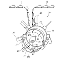
- FIG. 5 is a perspective view schematically showing a laser-type joining device in a manufacturing apparatus for a pants-type disposable diaper as an embodiment of a manufacturing apparatus for a sheet fusion body of the present invention.
- FIG. 1 is a perspective view schematically showing a pants-type disposable diaper as an example of a sheet fusion product manufactured according to the present invention.
- FIG. 2 is a cross-sectional view schematically showing a cross section taken along line II of FIG.
- FIG. 3 is a plan view schematically showing an unfold
- FIG. 6 is a perspective view schematically showing a pressure head in the laser type joining apparatus of the pants-type disposable diaper shown in FIG. 7A is a cross-sectional view taken along the line aa in FIG. 6, and FIG. 7B is a cross-sectional view taken along the line bb in FIG.
- FIG. 8 is a cross-sectional view schematically showing a cross-sectional structure passing through the rotation axis of the support member in the laser type bonding apparatus shown in FIG.
- FIG. 9 is a schematic diagram illustrating a state of the swinging motion (contacting / separating operation) of the pressure member that circulates along the peripheral surface of the support member.
- FIGS. 10A to 10C are schematic views sequentially showing the state until the pressure head in the swinging process state is in a pressure state.
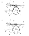
- FIGS. 13A to 13B are perspective views schematically showing an apparatus for manufacturing a pants-type disposable diaper as another embodiment (embodiment B) of the apparatus for manufacturing a sheet fusion body of the present invention.
- an object of the present invention is to provide a method and an apparatus for manufacturing a sheet fusion product that can eliminate the above-described drawbacks of the prior art.
- a pair of sheet fusion bodies that are objects to be manufactured according to the present invention that is, a sheet fusion body having a seal edge portion fused in a state where edges of a plurality of sheets overlap each other
- the present invention will be described by taking a pants-type disposable diaper having an exterior body having a side seal part as an example.
- the diaper 1 includes an absorbent main body 2 and an exterior body 3 that forms the outer surface of the diaper 1, and left and right side edges A1, A1 along the longitudinal direction X of the exterior body 3 in the front body F (abdominal side 1A). And the left and right side edges B1 and B1 along the longitudinal direction X of the exterior body 3 in the back body R (back side part 1B) are joined together to form a pair of side seal parts 4 and 4, a waist opening part 8 and a pair of leg openings. Portions 9 and 9 are formed.
- the exterior body 3 is positioned on the non-skin contact surface side of the absorbent main body 2 and fixes the absorbent main body 2.
- the diaper 1 has a longitudinal direction X corresponding to the wearer's front-rear direction and a lateral direction Y orthogonal to the wearer's front-rear direction in a developed and extended plan view as shown in FIG.
- the diaper 1 can be divided into a crotch part 1C arranged at the crotch part at the time of wearing, and an abdominal side part 1A and a back side part 1B located in the longitudinal direction X.
- the exterior body 3 in the crotch part 1 ⁇ / b> C is formed with recesses for forming leg openings 9, 9 at the left and right side edges along the vertical direction X.
- the diaper 1 can be divided into a front body F and a back body R with a virtual center line CL that bisects the diaper 1 in the vertical direction X as a boundary.
- a skin contact surface is a surface in the underpants type disposable diaper 1 or its component (for example, absorptive main body), and is turned to a wearer's skin side at the time of wear
- a non-skin contact surface is In the pants-type disposable diaper 1 or a component thereof, the surface is directed to the side opposite to the wearer's skin side (clothing side) when worn.
- the vertical direction X corresponds to the direction (longitudinal direction) along the long side of the absorbent main body 2 which is a disposable diaper or its constituent member
- the horizontal direction Y is the absorbent which is a disposable diaper or its constituent member. It coincides with the width direction of the main body 2.
- the absorbent main body 2 has a vertically long shape in which one direction (vertical direction X) is relatively long, and a surface sheet 2 a that forms a skin contact surface, and a non-skin contact A back sheet 2b that forms a surface, and a liquid-retaining absorbent 2c interposed between the two sheets.
- the absorbent 2c has a shape that is long in the same direction as the longitudinal direction X. .
- the absorptive main body 2 is joined to a central portion of the outer package 3 by a known joining means (adhesive or the like) with its longitudinal direction coinciding with the longitudinal direction X of the diaper 1 in the expanded and extended state.
- the expanded and extended state means that the side seal part is peeled off, the diaper is set in the expanded state, the elastic member of each part is expanded, and the design dimensions (the influence of the elastic member is completely eliminated). In this state, it is the same as the size when it is spread in a flat shape.
- the outer package 3 is disposed on the outer layer sheet 31 that forms the outer surface of the diaper 1 (the non-skin contact surface of the outer package 3), and the inner surface side of the outer layer sheet 31.
- An inner layer sheet 32 that forms the inner surface of 1 (skin contact surface of the exterior body 3), and a plurality of thread-like or belt-like elastic members 5, 6, and 7 fixed between the sheets 31 and 32 with an adhesive. It is configured to include.
- the two sheets 31 and 32 are joined to each other at a predetermined site by an adhesive or heat seal (not shown).
- the exterior body 3 includes a resin material at least partially, and is formed using the resin material as a main component.
- the resin material includes a heat-sealable synthetic resin such as polyethylene, polyethylene terephthalate, and polypropylene, and includes a nonwoven fabric, a film, a laminate sheet of a nonwoven fabric and a film, and the like.
- the nonwoven fabric include air-through nonwoven fabric, heat roll nonwoven fabric, spunlace nonwoven fabric, spunbond nonwoven fabric, and melt blown nonwoven fabric.
- the pair of side seal parts 4, 4 in the diaper 1 is formed so that the edge part of the exterior body 3 in the front body F and the edge part of the exterior body 3 in the back body R are the side seal parts 4. It has a seal edge portion 41 joined by a continuous linear fusion portion 40 extending in the longitudinal direction.
- the seal edge 41 in the diaper 1 is formed continuously over the entire length between the waist opening 8 and the leg opening 9 in each of the side seal portions 4 and 4.
- the fused portion 40 in the seal edge portion 41 is obtained by melting and solidifying constituent resins of the sheets in a state where the edge portions of a plurality of sheets (the outer layer sheet 31 and the inner layer sheet 32) constituting the exterior body 3 are overlapped. Is formed.
- the pants-type disposable diaper 1 having the above configuration can be manufactured, for example, by a method using an apparatus described below.
- the manufacturing method of the diaper 1 is a light-passage through which a laser beam can pass through a belt-shaped sheet stack in which a plurality of sheets are stacked, that is, a belt-shaped outer package 3 in which the front body side and the back body side are stacked.
- a pre-irradiation holding step in which the portion 27 is disposed on the outer surface of the support member 21 that travels in a predetermined direction and is held in a pressurized state on the outer surface, and is held on the outer surface of the support member 21 in a pressurized state.
- a belt-like sheet is formed by irradiating a laser beam from the support member 21 side through a light passage portion 27 to a seal-edge-formation-scheduled region (a site-schedule formation site) of the belt-shaped sheet laminate.
- the laminated body exitterior body 3
- the cut edges cut edges of the laminated body 3 in a laminated state of a plurality of sheets in a pressurized state caused by the fusion are fused together.
- a laser irradiation step and after the laser irradiation step, a cutting means 71a so as to traverse in a thickness direction of the sheet laminate with respect to a seal edge portion formation planned region of the sheet laminate (exterior body 3) irradiated with the laser beam.
- the cutting means insertion process which inserts is comprised.
- the main body fixing process which fixes the absorptive main body 2 manufactured by another process to the strip
- the absorbent main body 2 is fixed by folding the strip-shaped exterior body 3 (outer layer sheet 31, inner layer sheet 32) in the width direction.
- the front body side and the back body side of the formed strip-shaped outer package 3 are overlapped, whereby “a diaper continuous body in which a precursor of a pants-type disposable diaper in which a side seal portion is not formed is continuous in one direction” 10 "is manufactured.
- the belt-shaped outer package 3 in the superposed diaper continuous body 10 is held in a pressurized state.
- the belt-shaped outer package 3 in the diaper continuous body 10 was melted individually by the laser light 30 irradiation using the apparatus shown in FIG.
- a pants-type disposable diaper 1 having an exterior body 3 having a pair of side seal portions 4, 4 by fusing cut edges of a plurality of exterior bodies 3 (outer layer sheet 31, inner layer sheet 32) in a laminated state. Is manufactured continuously.
- the waist elastic member 5 that forms the waist gather the waist elastic member 6 that forms the waist gather
- the leg elastic member 7 that forms the leg gather have a predetermined elongation rate.
- a plurality of each are arranged in the stretched state.
- the leg elastic member 7 is arranged while forming a predetermined leg-circumferential pattern via a known swing guide (not shown) that reciprocates perpendicular to the sheet flow direction.
- the belt-shaped outer layer sheet 31 and the belt-shaped inner layer sheet 32 are coated with an adhesive coating machine (see FIG. (Not shown) to apply hot melt adhesive.
- an adhesive coating machine see FIG. (Not shown) to apply hot melt adhesive.
- the elastic members such as the waist elastic member 5 and the waistline elastic member 6 are fused in the sheets 31 and 32 by the irradiation of the laser light (the portion where the side seal portion 4 is to be formed, in FIG. 11 described later).
- a hot melt adhesive is intermittently applied to the waist elastic member 5 and the waist elastic member 6 by an adhesive application machine (not shown) before being arranged between the sheets 31 and 32. May be.
- a plurality of waistline elastic members 6 and a plurality of leg portion elasticities are made by using elastic member precut means (not shown) so as to correspond to positions where the absorbent main body 2 described later is disposed.
- the member 7 is pressed and divided into a plurality of pieces so that the contraction function is not expressed.
- the elastic member precut means include an elastic member dividing portion used in the method for manufacturing a composite elastic member described in JP-A-2002-253605.
- the absorbent main body 2 manufactured in a separate process is rotated by 90 degrees, and the inner layer sheet 32 constituting the strip-shaped outer package 3 to which an adhesive such as a hot melt adhesive is applied in advance. It is intermittently supplied and fixed on the top (main body fixing step).
- a leg hole LO ′ is formed inside the annular portion that is annularly surrounded by the leg elastic member 7 in the strip-shaped exterior body 3 in which the absorbent main body 2 is disposed.
- This leg hole forming step can be carried out by using a technique similar to that in a conventional method for manufacturing this type of article, such as a rotary cutter and a laser cutter.
- the strip-shaped exterior body 3 is folded in the width direction (a direction perpendicular to the conveying direction of the exterior body 3). More specifically, as shown in FIG. 4, both side portions 3 a, 3 a along the conveying direction of the strip-shaped outer package 3 are folded back so as to cover both longitudinal ends of the absorbent main body 2. After fixing both ends in the longitudinal direction, the outer package 3 is folded in the width direction together with the absorbent main body 2. In this way, the diaper continuous body 10 is obtained.
- the diaper continuum 10 thus manufactured is irradiated with laser light using a laser bonding apparatus 20 to form a pair of side seal portions 4 and 4 (laser irradiation step).
- a pants-type disposable diaper 1 having an exterior body 3 having a pair of side seal portions 4 is continuously manufactured.
- the laser bonding apparatus 20 will be described.
- the diaper continuous body 10 that is, a state in which a strip-shaped sheet stack in which a plurality of sheets are stacked is arranged on the outer surface.
- a support member 21 having a light passage part 27 through which laser light can pass and a seal edge of the diaper continuum 10 formed on the inner surface side of the support member 21 through the light passage part 27.
- An irradiation head 35 that irradiates the laser light to a predetermined region (a portion where the side seal portion is to be formed) is provided.
- a hollow cylindrical roll 23 that is a cylinder that is driven to rotate in the direction of arrow D is formed.
- the irradiation head 35 which irradiates the laser beam 30 toward the cylindrical support member 21 which is distribute
- the irradiation head 35 has a lens that collects the laser light 30.
- the cylindrical support member 21 has a first surface 21a facing outward and a second surface 21b facing inward.
- the irradiation head 35 is disposed on the second surface 21 b side of the support member 21.
- the support member 21 forms a peripheral surface portion (contact portion with the workpiece) of the cylindrical roll 23, and a pair of annular frames (both ends of the cylindrical roll 23 in the rotational axis direction) ( (Not shown).
- the support member 21 is made of a metal material such as iron, aluminum, stainless steel, or copper, or a material having heat resistance such as ceramics.
- the support member 21 has a light passage portion 27 through which laser light can pass. As shown in FIG. 5, the support member 21 has a slit-shaped opening 27 that penetrates the support member 21 in the thickness direction as a light passage portion.
- the opening 27 has a rectangular shape in plan view, and the longitudinal direction of the opening 27 intersects with the conveyance direction D of the diaper continuous body 10 (band-shaped exterior body 3). More specifically, the opening 27 It extends so as to coincide with a direction parallel to the axial direction of the rotating shaft, and a plurality of them are provided at predetermined intervals along the circumferential direction (conveying direction D) of the cylindrical support member 21.
- the support member 21 allows the laser light to pass through the opening 27, but does not allow the laser light to pass (transmit) at portions other than the opening 27.
- a method of forming the opening 27 in the support member 21 1) etching and punching a predetermined portion of the support member 21 made of a single annular member having the same length as the circumference of an annular frame (not shown).
- a method of drilling the opening 27 by laser processing or the like, and 2) a plurality of curved rectangular members are used as the support member 21 instead of a single annular member, and the plurality of members are used as a pair of frames.
- the length in the longitudinal direction of the opening 27 is formed to be longer than the length of the portion to be blown (side seal portion) of the diaper continuous body 10 supported by the support member 21. ing.
- the irradiation head 35 is a galvano scanner (an apparatus having a motor shaft with a mirror) that freely scans the laser light 30, and the laser light 30 is parallel to the rotation axis of the cylindrical roll 23.
- a mechanism for making the spot diameter of the laser beam 30 constant is provided.
- the laser irradiation mechanism can arbitrarily move the irradiation point of the laser light 30 in both the circumferential direction of the cylindrical roll 23 and the direction orthogonal to the circumferential direction.
- the laser type bonding apparatus 20 includes a plurality of pressure heads 26 as pressure members in addition to the support member 21 and the irradiation head 35 described above.
- the pressure head 26 is used to press the diaper continuous body 10 supported on the first surface 21 a of the support member 21 described above, and one pressure head 26 is provided for one opening 27. ing.
- Each pressure head 26 has a rotation axis on an extension line of the rotation axis of the cylindrical roll 23, and is arranged on the peripheral surface of the second cylindrical roll 25 arranged adjacent to the cylindrical roll 23.
- the second cylindrical roll 25 rotates in synchronization with the cylindrical roll 23.
- each pressure head 26 is attached to a second cylindrical roll 25, which is a separate member from the cylindrical roll 23. Instead, each pressure head 26 is attached to the cylindrical roll 23. It is also possible to attach.
- each pressurizing head 26 is in the same direction as the rotation direction of the support member 21 constituting the cylinder of the cylindrical roll 23 and the circumference of the support member 21. It is possible to go around along the peripheral surface of the support member 21 at the same speed as the speed.
- the longitudinal direction X1 of the pressure head 26 is perpendicular to the circumferential direction of the cylindrical support member 21, that is, the conveyance direction of the diaper continuous body 10
- the width direction Y1 is the circumferential direction of the cylindrical support member 21, that is, It arrange
- the pressure head 26 includes a main body portion 50A and a pressure portion 50B.
- the main body portion 50A has a longitudinal direction X1 and a width direction Y1 orthogonal thereto, and is constituted by a vertically long block body along the longitudinal direction X1.
- the main body 50A has a front end 52a at one end in the longitudinal direction X1 and a rear end 52b at the other end.
- a connecting member 53 is connected to the rear end portion 52b.
- the main body portion 50 has a main body hollow portion 51 therein.
- the main body hollow portion 51 has a circular cross section and extends along the longitudinal direction X1 of the main body portion 50.
- the main body hollow portion 51 communicates with the connection member 53 at the position of the rear end portion 52 b of the main body portion 50.
- the connection member 53 is connected to suction means (not shown).
- the pressurizing unit 50B includes a pair of local pressurizing members 54 and 54 depending from the lower surface of the main body 50A.
- the local pressurizing member 54 is a vertically long plate-like member extending in the longitudinal direction X1, and is formed integrally with the main body 50A.
- the local pressure member 54 has a predetermined thickness along the width direction Y1, and the lower surface thereof is a pressure surface 54A.
- the pressing surface 54A is a flat surface.
- the local pressing member 54 is used to locally press the diaper continuous body 10 (sheet laminated body) supported on the first surface 21a of the supporting member 21 by the pressing surface 54A.
- the pair of local pressure members 54, 54 are arranged in parallel in a non-contact state at a predetermined interval along the width direction Y1. Therefore, a space S is provided between the pair of local pressure members 54 and 54.
- the space S extends along the longitudinal direction X1 of the pressure head 26 and also extends along the longitudinal direction of the pressure head 26.
- the space S communicates with the main body hollow portion 51 provided inside the main body portion 50A described above.
- the space S is open at the lower ends of the pair of local pressure members 54, 54. This opening functions as the air suction port 55.
- the space S communicates with the main body hollow portion 51, the main body hollow portion 51 communicates with the connection member 53, and the connection member 53 is connected to suction means (not shown).
- the pressure head 26 includes an air suction part having the air suction port 55. That is, the pressurizing head 26 has a function of pressurizing the diaper continuous body 10 supported on the first surface 21 a of the support member 21 and a function of sucking and removing the gas generated by the irradiation of the laser beam 30. It has two functions.
- the width of the air suction port 55 (the length along the width direction Y1 in FIG. 7B) is the width of the slit-like opening 27 in the support member 21 described above (the circumferential direction of the support member 21). Length). However, in some cases, the width of the air suction port 55 can be made equal to or smaller than the width of the slit-shaped opening 27.
- the length of the air suction port 55 (the length along the longitudinal direction X1 in FIG. 7A) only needs to be larger than the length of the diaper fusing scheduled portion (side seal portion).
- the length of the air suction port 55 is larger than the length of the slit-shaped opening 27 in the support member 21 (the length along the axial direction of the support member 21). It has become.
- the pressure head 26 is in contact with the outer surface which is the first surface 21 a of the support member 21 so that the air suction port 55 formed on the pressure head 26 covers the entire slit-shaped opening 27 of the support member 21. Placed in. That is, the air suction port 55 extends in the same direction as the direction in which the slit-shaped opening 27 provided in the support member 21 extends, and is disposed opposite to the slit-shaped opening 27.
- the local pressure member 54 is located at the position on the first surface 21a side of the support member 21 so that the pressure surface 54A is in the same direction as the air suction port 55 extends as shown in FIG.
- a pair of pressure surfaces 54 ⁇ / b> A are disposed adjacent to the air suction port 55 so as to extend in the direction and are positioned with the air suction port 55 interposed therebetween.
- FIG. 8 shows the operation of the pressure head 26 having the above configuration.
- FIG. 8 schematically shows an essential part of a cross section of the laser-type bonding apparatus 20.
- This figure is a longitudinal sectional view passing through the rotation axis of the cylindrical roll 23 and the support member 21.
- the pressure head 26 is supported by a hinge structure at the longitudinal direction X1, in other words, at the rear end 52b that is one end in the direction in which the air suction port 55 provided in the pressure head 26 extends.
- the support part 24 is attached to the second rotating roll 25.
- the pressurizing head 26 can swing in a plane passing through the rotation axis of the support member 21, for example, in the plane of FIG. 8 with the support portion 24 as a fulcrum.
- the range in which the pressure head 26 performs the swinging motion is such that the pressure surface 54 ⁇ / b> A of the pressure head 26 is sufficiently separated from the peripheral surface of the support member 21 and is introduced into the peripheral surface of the support member 21.
- the pressure surface 54 ⁇ / b> A is the circumferential surface of the support member 21.
- a known means may be used as appropriate.
- a cam mechanism, a cylinder mechanism, or a servo motor can be used.
- the pressure member 54 can be moved toward and away from the first surface 21 a of the support member 21.
- the pressure head 26 can be configured to be capable of reciprocating along the radial direction of the support member 21. In this way, while the pressure head 26 circulates along the peripheral surface of the support member 21, the pressure head 26 reciprocates along the radial direction of the support member 21.
- the pressure head 26 repeats the contact / separation operation with respect to the first surface 21 a of the support member 21.
- the means for reciprocating the pressure head 26 is the same as the means for swinging the pressure head 26. For example, a cam mechanism, a cylinder mechanism, or a servo motor may be used.
- FIG. 9 is a schematic diagram showing the state of the swinging motion (contacting / separating operation) of each pressure head 26 that circulates along the peripheral surface of the support member 21.
- the diaper continuous body 10 supported on the first surface 21a of the support member 21 is melted to become individual diapers 1 when leaving the support member 21, but for convenience of explanation, the same diaper 1 is used.
- it is drawn as a continuum.
- Each pressurizing head 26 has a different state depending on each position on the first surface 21 a of the support member 21. When the pressure head 26 is viewed along the circumferential direction of the support member 21, it is in an open state A, a swing process state (pressurization process state) B1, a pressurization state C, and a swing process state (open process state). ) Broadly divided into B2.
- Such an operation of the pressurizing head 26 is an example of the present invention, and it is not impeded that the pressurizing head 26 performs an operation different from this to melt the diaper continuous body 10.
- the pressurized state C is a fan-shaped range that is located 180 degrees opposite to the range of the open state A and has a wider central angle than the center angle of the fan-shaped state of the open state A.
- the swinging process state appears during the transition from the open state A to the pressurized state C (swinging process state B1) when viewed along the rotation direction of the support member 21, and from the pressurized state C to the open state. It also appears during the transition to A (rocking process state B2).
- the open state A is a state shown on the upper side in FIG. 8 described above, and is a fully open state in which the pressure surface 54A of the pressure head 26 is sufficiently separated from the peripheral surface of the support member 21.
- the pressurization state C is a state shown on the lower side in FIG. 8, in which the pressurization surface 54 ⁇ / b> A of the pressurization head 26 is parallel to the peripheral surface of the support member 21. In this state, the diaper continuous body 10 supported on the first surface 21a of the support member 21 is reliably pressurized by the pressure head 26, and fusing by the laser light 30 is performed under the pressurized state. Subsequent fusion can be done successfully.
- the swinging process state B1 the swinging of the pressure head 26 in the open state is started, and the pressure surface 54A of the pressure head 26 approaches toward the first surface 21a of the support member 21.
- swinging of the pressure head 26 in the pressurized state is started, and the pressure surface 54 A of the pressure head 26 is separated from the first surface 21 a of the support member 21.
- the open state A As described above, in the present embodiment, when attention is paid to one pressure head 26, while the pressure head 26 performs one round motion along the peripheral surface of the support member 21, the open state A ⁇ The operation of the swinging process state B1 going to pressurization ⁇ the pressurizing state C ⁇ the swinging process state B2 going to release is performed as one cycle operation.
- FIG. 10A to 10C sequentially show states until the pressure head 26 in the swinging process state B1 reaches the pressure state C.
- FIG. 10A shows a state immediately before the pressure head 26 enters the pressure state C.
- the local pressure member 54 of the pressure head 26 is not in contact with the diaper continuous body 10 supported by the first surface 21 a of the support member 21.
- illustration of the diaper continuous body 10 is omitted for convenience of explanation.
- the pressure head 26 comes into contact with the diaper continuous body 10 as shown in FIG. 10B.
- the pressing surface 54A at the tip of the pair of local pressing members 54, 54 in the pressing member 26 sandwiching the opening 27 locally presses and presses the diaper continuous body 10. That is, the diaper continuous body 10 supported on the first surface 21 a of the support member 21 is locally pressurized by the local pressure member 54 at positions on both sides of the opening 27.
- the diaper continuous body 10 positioned on the pair of local pressure members 54 ensures that a plurality of sheets constituting it are in close contact with each other.
- the laser beam 30 is irradiated toward the diaper continuum 10 in a close contact state realized by this local pressurization. Then, the gas generated due to the irradiation of the laser beam 30 passes through an air suction port 55 (see FIG. 7 and the like) by an air suction part provided in the pressure head 26 as shown in FIG. Aspirated and removed.
- the gas generated when processing the diaper continuous body 10 by irradiation with the laser light 30 is the air disposed on the first surface 21a side in the support member 21 that supports the diaper continuous body 10. Since suction is performed by the suction unit, the gas can be efficiently sucked. Therefore, it is possible to effectively prevent ignition and the like due to the resin fume contained in the gas. Further, since the generated fumes are preferably prevented from adhering and depositing on the pressure surface 54A of the support member 21 and the pressure head 26, it is effective to generate defective products due to the deposit transferring to the product. Can be prevented.
- the diaper continuous body 10 is locally pressurized only at positions on both sides of the slit-shaped opening 27, and the laser light 30 is irradiated under the locally pressurized state. Further, the sheets constituting the diaper continuous body 10 can be reliably fused to each other, and the fused portion 40 (see FIG. 2) having sufficient strength can be formed.
- the diaper continuous body 10 is continuously transported, and one surface thereof forms the peripheral surface portion of the cylindrical roll 23 and the slit-like opening 27 (through which the laser beam 30 can pass). It arrange
- the diaper continuous body 10 is melted at the same time, and at the same time, the cut edges of the plurality of sheets (exterior body 3) in the pressurized state are melted in an overlapped state.
- the side seal portion 4 is formed by wearing (laser irradiation step).
- FIG. 11A to 11C show a state in which the side seal portion 4 (seal edge portion) is formed at the same time that the diaper continuous body 10 (band-shaped sheet laminate) is melted using the laser-type bonding apparatus 20. It is a figure explaining.
- FIG. 11A schematically shows a seal edge formation planned region of the diaper continuous body 10, that is, a seal edge formation planned site 10 ⁇ / b> C and its vicinity.
- parts of the diaper continuous body 10 in the aspect of illustration are the centers of the longitudinal direction (conveyance direction D) in the area
- Such a seal edge portion formation planned portion 10C has an eight-layer structure portion where eight sheets are stacked at the opening end portion of the waist opening portion 8 (see FIG. 1) and its vicinity, and four other portions.
- the four-layer structure portion includes two sheets (an outer layer sheet 31 and an inner layer sheet 32) constituting one exterior body 3 in the ventral side part 1A, and a back side part 1B. It consists of the same two sheets 31 and 32 that constitute one exterior body 3, and these four sheets are laminated.
- the eight-layer structure portion is folded so that both side portions 3a and 3a of the strip-shaped outer package 3 cover both longitudinal ends of the absorbent main body 2 when the diaper continuous body 10 is manufactured ( (See FIG. 3 and FIG. 4), because there are two exterior bodies 3 on each of the abdominal part 1A and the back side part 1B, and these four exterior bodies 3, 3 are laminated, As a result, eight sheets 31 and 32 are laminated.
- elastic members such as the waist elastic member 5 and the waistline elastic member 6 may be interposed between the overlapping sheets 31 and 32, In FIG. 4 described above, the elastic member is omitted from the viewpoint of easy explanation.
- the 4-layer structure portion will be mainly described, but unless otherwise specified, the 8-layer structure portion is configured in the same manner as the 4-layer structure portion, and the side seal portion 4 is formed.
- the “seal edge formation scheduled region” is defined as a region including the seal edge formation planned site 10C and the vicinity thereof, and specifically, a diaper continuous centering on the seal edge formation planned site 10C. The range of 10 mm respectively before and behind the conveyance direction of the body 10 (band-shaped sheet laminated body) is pointed out.
- the outer layer sheet 31 constituting the contact surface with the support member 21, which is one surface of the diaper continuous body 10, and the one surface are configured. Any one or both of the sheets other than the sheet (inner layer sheet 32) absorb the laser beam 30 and generate heat.
- all of the four sheets 31 and 32 constituting the seal edge portion formation planned site 10 ⁇ / b> C are sheets (nonwoven fabrics) that absorb the laser beam 30 and generate heat.
- the two sheets of the outer layer sheet 31 and the inner layer sheet 32 that overlap each other in the vicinity of the seal edge formation planned site 10C may be joined by an adhesive or the like before the irradiation with the laser beam 30. It does not need to be joined.
- the diaper continuous body 10 has one surface 10a in contact with the support member 21, and a seal edge portion formation planned portion 10C (a portion where the side seal portion 4 is formed) is a slit-shaped opening. It is introduced onto the support member 21 that rotates in the direction of arrow D so as to be positioned on the portion 27, and the local pressure member 54 of the pressure head 26 is pressed against the other surface 10b, thereby It is pressed (compressed) in the thickness direction while being conveyed (pre-irradiation holding step). And the laser beam 30 is irradiated via the opening part 27 from the support member 21 side with respect to the seal edge part formation plan area
- the irradiation point of the laser beam 30 is configured to be arbitrarily movable in the circumferential direction of the cylindrical roll 23 and is set so as to follow the movement of the opening 27 along the circumferential direction. Therefore, the laser beam 30 is continuously irradiated to the seal edge portion formation planned portion 10C located on the opening portion 27 for a certain period of time during the conveyance.
- the forming materials (fibers and the like) of the sheets 31 and 32 existing in the seal edge formation planned portion 10C are obtained by direct irradiation of the laser beam 30.
- the forming material is vaporized by heat generation and disappears, and the forming material existing in the vicinity of the seal edge portion formation planned site 10C is indirectly heated by the laser beam 30 and melted.
- the vaporized gas is sucked into the pressure head 26 through the air suction port 55 of the pressure head 26 and discharged to the outside.
- the seal edge formation planned region of the four-layer structure is melted and the diaper continuous body 10 to 1
- the diaper continuous body 10 is melted in a form in which two sheet laminates (diaper precursors) are cut, four sheets 31 in the sheet laminate produced by the melting, The cut edges of 32 and the cut edges of the four sheets 31 and 32 in the cut diaper continuous body 10 are fused together. Each of these cut edges is pressed (compressed) by being sandwiched between the support member 21 and the pressure head 26 before the formation (before the diaper continuous body 10 is melted by irradiation with the laser beam 30). ).
- the outer body 3 in a pressurized state at two locations caused by the melting of the belt-shaped outer body 3 and the melting of the belt-shaped outer body 3 by one laser light irradiation as described above.
- the fusion and fusing are the same with approximately half the laser output compared to the method of fusing the two fusion spots by two laser beam irradiations.
- the diaper 1 can be manufactured efficiently by performing the process.
- the cut edges of the sheets 31 and 32 are heated and melted during the irradiation of the laser beam 30 and immediately after the end of the irradiation, but are separated from the diaper continuous body 10 by the irradiation of the laser beam 30.
- Each of the leaf diaper precursor and the diaper continuous body 10 is quickly cooled and solidified by the outside air after the irradiation is completed while the pressure state of the support member 21 and the pressure head 26 is maintained.
- the edge forming material (fiber or the like) is fused and integrated into the fused portion 40 (holding step after irradiation).
- the laser beam 30 is irradiated with another opening 27 whose irradiation point is adjacent to the direction opposite to the transport direction D. And is irradiated to another seal edge formation planned site 10 ⁇ / b> C located thereabove via the other opening 27.
- another seal edge portion formation scheduled region is divided and fused in the same manner as described above, and the other side seal portion 4 (fused portion 40) that forms a pair with the previously formed side seal portion 4 is formed.
- the pants-type disposable diaper 1 including the exterior body 3 having the pair of side seal portions 4 and 4 is continuously manufactured.
- the wavelength of the laser beam irradiated to the diaper continuous body 10 is absorbed by the sheets (outer layer sheet 31 and inner layer sheet 32) constituting the outer package 3 and generates heat.
- the laser beam is used.
- the “sheet constituting the exterior body” is not limited to the sheet (for example, the outer layer sheet 31 in the above-described embodiment) constituting one surface of the exterior body (the contact surface with the support member 21). Any sheet may be used as long as it constitutes.
- the laser light applied to the exterior body is a wavelength that is absorbed by the sheet and generates heat for the individual sheets constituting the exterior body depends on the material of the sheet and the wavelength of the laser light to be used. It depends on the relationship.
- the laser light can be CO2 laser, YAG laser.
- LD laser semiconductor laser
- seat which comprises an exterior body contains polyethylene, a polyethylene terephthalate, a polypropylene etc. as a synthetic resin, as a wavelength which can be absorbed by this sheet
- the spot diameter of laser light, laser output, and the like can be appropriately selected in consideration of the material and thickness of the sheet constituting the exterior body.
- the sheet laminate with respect to the region where the seal edge portion is to be formed of the sheet laminate (exterior body 3) irradiated with laser light after the laser irradiation step, the sheet laminate with respect to the region where the seal edge portion is to be formed of the sheet laminate (exterior body 3) irradiated with laser light.
- the cutting means insertion portion 70 has a rotary die cutter 71 and an anvil roll 72.
- the rotary die cutter 71 has a cutting blade 71a as a cutting means.
- the cutting blade 71a is laminated on the laser irradiation portion of the sheet laminate (exterior body 3). It is inserted so as to cross in the thickness direction of the body.
- a single-piece diaper precursor cut from the diaper continuous body 10 by irradiation of the laser beam 30 is transported and supplied to the cutting means insertion portion 70.
- a belt conveyor 60 is provided.
- the belt-like sheet laminate is melted.
- fusing by laser irradiation may not be performed well at a portion where a double-sided tape or an old sheet laminate and a new sheet laminate overlap.
- the cutting means insertion portion 70 the cutting means is inserted so as to cross in the thickness direction of the sheet laminated body with respect to the seal edge portion formation scheduled region of the sheet laminated body irradiated with the laser beam.
- Embodiment A of the manufacturing method of the diaper 1 (sheet fusion body), in the cutting means insertion step, the cutting means is inserted into all the seal edge portion formation scheduled areas of the sheet laminate to be conveyed. Specifically, as shown in FIG. 12 (a), in the laser irradiation process, the diaper continuum 10 is melted and a single-wafer diaper precursor is formed, but between all diaper precursors, that is, diaper continuation. The cutting blade 71a is inserted so as to traverse in the thickness direction of the diaper continuous body with respect to all the seal edge portion formation scheduled regions of the body.
- FIG. 13 shows another embodiment (embodiment B) of the manufacturing method of the diaper 1 (sheet fusion product).
- the embodiment B has a detection step for detecting good / bad fusing of the seal edge formation scheduled region of the sheet laminate in the laser irradiation step, and in the cutting means insertion step, the fusing failure was detected by the detecting step.
- the cutting means 71a is inserted into the seal edge portion formation scheduled region. That is, it has the detection part 80 which detects the quality of the fusing of the sealing edge part formation plan area of a sheet laminated body by a laser beam.
- the detection unit 80 determines whether or not fusing is good or bad based on the detection result of the sensor 81 and the sensor 81 that detects the presence or absence of fusing in the seal edge formation scheduled region of the sheet laminate conveyed on the support member, It has the judgment part 82 which inserts the cutting
- the sensor 81 seals when the pressure head 26 is in the swinging process state (opening process state) B2, that is, when the pressure head 26 is away from the diaper continuous body 10. It is provided at a position where the edge formation scheduled region can be detected.
- the rotary die cutter 71 can be separated from the anvil roll 72 by driving means (not shown).
- the determining unit 82 When determining that the fusing is good, the determining unit 82 separates the rotary die cutter 71 from the anvil roll 72 at a position where the cutting blade 71a cannot cross in the thickness direction of the sheet laminate (FIG. 13A). On the other hand, when it is determined that the fusing is defective, the rotary die cutter 71 is positioned at a position where the cutting blade 71a can traverse in the thickness direction of the sheet laminate (FIG. 13B). In Embodiment B, since the cutting edge 71a is not inserted into the seal edge formation scheduled region that is determined to be good fusing, that is, the portion that has been cut by the laser irradiation process, the seal edge formation is ensured. The cutting area can be divided, and the life of the cutting blade 71a can be improved.
- the rotary die cutter 71 can be separated from the anvil roll 72, but the rotary die cutter 71 is not separated, and the sheet stack of the rotary die cutter 71 is determined based on the judgment of fusing quality. It is also possible to change the pressure in the body thickness direction. Specifically, when it is determined that the fusing is good, the rotary die cutter 71 is inserted with a low pressure against the part where the fusing has been performed, and no unnecessary force is applied to the cutting blade 71a.
- the rotary die cutter 71 is switched to a high pressing force, whereby the cutting blade 71a is inserted with a high pressing force, and the cutting blade 71a is reliably sealed by the pressing force against the anvil roll 72. It is divided at the edge formation scheduled region.
- the rotary die cutter 71 can be made to cut
- the pressing force in the thickness direction of the sheet laminate of the rotary die cutter 71 can be switched by an air cylinder. Also in the embodiment B, the position where the cutting means 71a is inserted is not necessarily coincident with the portion irradiated with the laser beam as long as it is within the seal edge portion formation scheduled region.
- the cutting means insertion portion 70 has a cutting blade as the cutting means 71a.
- the cutting means 71a is a laser beam, and in the cutting means insertion step, sheet lamination is performed. You may irradiate a laser beam again so that the laser irradiation site
- a laser beam as the cutting means 71a, the durability and maintainability of the apparatus by non-contact processing are improved. Further, if image detection is performed using the detection unit as described above, it is sufficient to irradiate only the portion with poor fusing, which has the effect of reducing the energy used.
- the intensity of the laser beam is preferably higher than the intensity of the laser beam used in the laser irradiation process, which is the previous process, from the viewpoint of reliably dividing the sheet laminate in the region where the seal edge portion is to be formed.
- the position where the laser beam is irradiated again in the cutting means insertion step does not necessarily need to coincide with the portion irradiated with the laser beam in the laser irradiation step as long as it is within the seal edge formation scheduled region.
- a strip-shaped outer package is a stack of four sheets as shown in FIG. 11 (a), or two, three, or five or more sheets. May be.
- the exterior body 3 in the above embodiment is not divided into the ventral portion 1A and the dorsal portion 1B, but is an hourglass shape extending over the ventral portion 1A, the crotch 1C, and the dorsal portion 1B.
- the exterior body to be processed according to the present invention is not limited to such a continuous shape, and is, for example, an abdomen placed on the wearer's belly side (front side). It is divided
- seat member distribute
- the pre-irradiation holding step in the manufacturing method of the pants-type disposable diaper having such a split type exterior body includes a front body side (a belt-like stomach side sheet member) and a rear side of the belt-like exterior body to which the absorbent main body is fixed.
- the part where the side seal portion is to be formed in the belt-shaped exterior body having a configuration in which the body side (the belt-shaped back sheet member) is superimposed is brought into a pressurized state.
- both side parts along the conveyance direction of each inner layer sheet 32 were folded back so as to cover both ends in the longitudinal direction of the absorbent main body 2, the width direction (longitudinal direction) of the band-shaped outer layer sheet 31 was more than the band-shaped inner layer sheet 32. Absorbs only the extension part of the outer layer sheet 31 that extends outward from the side edge of the inner layer sheet 32 when the sheets 31 and 32 are overlapped.
- the body 2 may be folded back so as to cover both ends in the longitudinal direction.
- the seal edge portion formation planned portion 10C of the diaper continuum 10 is such that the opening end portion of the waist opening portion 8 and the vicinity thereof are a six-layer structure portion in which six sheets are stacked, and the other portions are four. It becomes a four-layer structure portion in which sheets are stacked.
- belt-shaped inner layer sheet 32, do not need to be folded.
- the laser type bonding apparatus 20 including the cylindrical roll 23 is used.
- the laser type bonding apparatus 20 including a flat plate member may be used instead of the cylindrical roll 23.
- the present invention can be similarly provided for the production of other forms of sheet fusion bodies.
- a method for producing a sheet fusion body having a seal edge fused in a state where edges of a plurality of sheets are overlapped A strip-shaped sheet stack in which a plurality of sheets are stacked is disposed on the outer surface of a support member having a light passage portion through which laser light can pass and traveling in a predetermined direction, and in a pressurized state on the outer surface.
- a method for producing a sheet fusion body comprising:
- the sheet fusion body manufacturing method according to ⁇ 1> wherein the cutting means is inserted into all the seal edge portion formation scheduled regions of the sheet stack to be conveyed.
- ⁇ 3> Having a detection step of detecting good or defective fusing of the seal edge formation scheduled region of the sheet laminate in the laser irradiation step,
- the cutting means insertion step the sheet fusion body manufacturing method according to ⁇ 1>, wherein the cutting means is inserted into a seal edge portion formation scheduled area detected as a fusing defect in the detection step.
- the sheet laminate is held in the pressurized state by a pressure member that presses the sheet laminate on the outer surface of the support member from a surface opposite to the contact surface of the sheet laminate.
- a pressure member that presses the sheet laminate on the outer surface of the support member from a surface opposite to the contact surface of the sheet laminate.
- the insertion of the cutting means in the cutting means insertion step is to irradiate the laser light again so as to cross the seal edge formation scheduled region of the sheet laminate in the thickness direction of the sheet laminate. ⁇ 1> thru
- the cutting means is a cutting blade, and in the cutting means inserting step, the cutting blade is inserted so as to cross the laser irradiation portion of the sheet laminate in the thickness direction of the sheet laminate, Having a detection step of detecting good or defective fusing of the seal edge formation scheduled region of the sheet laminate in the laser irradiation step, The pressing force of the cutting blade in the thickness direction of the sheet laminate can be changed, and the cutting blade can be applied with a low pressing force to the seal edge formation scheduled area detected as good fusing by the detection step.
- a pants-type disposable diaper for producing a pants-type disposable diaper having an exterior body having a pair of side seal portions as a sheet-fused body having a seal edge fused in a state where the edges of a plurality of sheets are overlapped Manufacturing method.
- An absorbent main body and an exterior body forming an outer surface of the diaper are provided, and right and left side edges along the longitudinal direction of the exterior body in the front body and left and right side edges along the longitudinal direction of the exterior body in the back body are joined.
- a pair of side seals, a waist opening, and a pair of leg openings, and the outer body is located on the non-skin contact surface side of the absorbent main body and fixes the absorbent main body
- a belt-shaped sheet stack in which a plurality of sheets are stacked is irradiated with a laser beam to melt the sheet, and the cut edges of the plurality of sheets generated by the fusing are fused together to have a seal edge.
- a sheet fusion body manufacturing apparatus for continuously manufacturing a plurality of sheet fusion bodies, A support member having a light passage portion that travels in a predetermined direction in a state where the belt-shaped sheet laminate is arranged on the outer surface, and through which laser light can pass, An irradiation head that is arranged on the inner surface side of the support member and irradiates the laser beam to the seal edge portion formation planned region of the sheet laminate through the light passage portion,
- a sheet fusion body comprising: a cutting means insertion portion including a cutting means inserted into the seal edge portion formation scheduled region irradiated with the laser beam so as to cross the thickness direction of the sheet laminate. apparatus.
- the sheet fusion body manufacturing apparatus according to ⁇ 11>, wherein the cutting unit is inserted into all the seal edge portion formation scheduled areas of the sheet laminate to be conveyed.
- the cutting means has a detection unit for detecting good or bad fusing of the seal edge formation scheduled region of the sheet laminate by the laser light, and the cutting means is used for the seal edge formation planned region determined by the detection unit as fusing failure.
- ⁇ 14> A pressure member that pressurizes the sheet laminated body disposed on the outer surface of the support member from the side opposite to the support member side; ⁇ 11> thru
- the insertion of the cutting means in the cutting means insertion part is to irradiate the laser light again so as to cross the seal edge formation scheduled region of the sheet laminate in the thickness direction of the sheet laminate. ⁇ 11> thru
- the cutting means is a cutting blade, and the cutting means insertion portion inserts the cutting blade so as to cross in the thickness direction of the sheet laminate with respect to the seal edge portion formation scheduled region of the sheet laminate, Having a detection unit for detecting good / bad fusing of the seal edge formation scheduled region of the sheet laminate by the laser beam, It is possible to change the pressing force of the cutting blade in the thickness direction of the sheet laminate, and the cutting blade has a low pressing force with respect to the seal edge formation planned area detected by the detection unit as good fusing.
- Manufacturing equipment. ⁇ 18> The sheet fusion body according to any one of ⁇ 14> to ⁇ 17>, wherein the pressurizing member has an air suction part, and gas generated by fusing is sucked and removed by the air suction part. Manufacturing equipment.
- the pressure member includes a local pressure member having a pressure surface that locally pressurizes the sheet laminate supported on the outer surface of the support member;
- the light passage portion is a slit-like opening that penetrates the support member in the thickness direction, and extends in such a manner that its longitudinal direction coincides with a direction parallel to the axial length direction of the rotation axis of the cylindrical roll.
- ⁇ 23> The apparatus according to any one of ⁇ 11> to ⁇ 22>, Used to manufacture a pants-type disposable diaper having an exterior body having a pair of side seal portions, as a sheet fusion body having a seal edge portion fused with the edges of a plurality of sheets overlapping. Pants-type disposable diaper manufacturing equipment.
- An absorbent main body and an exterior body forming an outer surface of the diaper are provided, and right and left side edges along the longitudinal direction of the exterior body in the front body and left and right side edges along the longitudinal direction of the exterior body in the back body are joined.
- a pair of side seals, a waist opening, and a pair of leg openings, and the outer body is located on the non-skin contact surface side of the absorbent main body and fixes the absorbent main body.
- the absorbent main body manufactured in a separate step is intermittently supplied and fixed on the inner layer sheet constituting the belt-shaped outer package, and then a leg hole is formed in the outer package, Next, the belt-shaped outer package is folded in a direction perpendicular to the conveying direction of the outer package, thereby obtaining a continuous diaper, Next, a pants-type disposable diaper having a pair of side seal portions formed by irradiating the diaper continuous body with a laser beam using a laser-type bonding apparatus and having an exterior body having the pair of side seal portions.
- the manufacturing apparatus of the underpants type disposable diaper as described in said ⁇ 23> or ⁇ 24> which manufactures 1 continuously.
- the outer package After folding both sides along the transport direction of the belt-shaped outer package so as to cover both longitudinal ends of the absorbent main body and fixing both longitudinal ends of the absorbent main body, the outer package is fixed to the absorbent main body.
- the manufacturing apparatus of the underpants type disposable diaper any one of said ⁇ 23> thru
Landscapes
- Engineering & Computer Science (AREA)
- Mechanical Engineering (AREA)
- Physics & Mathematics (AREA)
- Optics & Photonics (AREA)
- Health & Medical Sciences (AREA)
- Toxicology (AREA)
- Plasma & Fusion (AREA)
- Electromagnetism (AREA)
- Textile Engineering (AREA)
- Vascular Medicine (AREA)
- Veterinary Medicine (AREA)
- Public Health (AREA)
- General Health & Medical Sciences (AREA)
- Animal Behavior & Ethology (AREA)
- Life Sciences & Earth Sciences (AREA)
- Heart & Thoracic Surgery (AREA)
- Biomedical Technology (AREA)
- Epidemiology (AREA)
- Absorbent Articles And Supports Therefor (AREA)
- Lining Or Joining Of Plastics Or The Like (AREA)
Abstract
La présente invention concerne les étapes suivantes : une étape de maintien de pré-émission durant laquelle un corps stratifié de feuille en forme de bande dans lequel des feuilles sont stratifiées est agencé sur la surface extérieure d'un élément de support (21) qui possède une partie de transmission de lumière (27) à travers laquelle la lumière laser peut passer, et le corps stratifié en feuille est maintenu dans un état sous pression; une étape d'émission laser durant laquelle une lumière laser est émise, à partir d'un côté d'élément de support (23) et via la partie de transmission de lumière (27), sur une région prévue de formation de bord de joint d'étanchéité du corps stratifié de feuille qui est maintenu sur l'élément de support (21) dans un état sous pression, ce qui permet le découpage thermique du corps stratifié de feuille en forme de bande, et simultanément le découpage de bords qui ont été générés par le découpage thermique et font partie de la pluralité de feuilles qui sont dans l'état sous pression et sont fusionnées à chaud, de façon à former ainsi les parties de bord de joint d'étanchéité; et une étape d'insertion de moyen de coupe consistant à insérer, dans la direction d'épaisseur du corps stratifié de feuille, un moyen de coupe (71a) dans la région prévue de formation de bord de joint d'étanchéité sur laquelle la lumière laser a été émise.
Priority Applications (1)
| Application Number | Priority Date | Filing Date | Title |
|---|---|---|---|
| CN201580066552.5A CN106999319B (zh) | 2014-12-15 | 2015-11-19 | 片熔接体的制造方法和制造装置 |
Applications Claiming Priority (2)
| Application Number | Priority Date | Filing Date | Title |
|---|---|---|---|
| JP2014-252864 | 2014-12-15 | ||
| JP2014252864A JP6389113B2 (ja) | 2014-12-15 | 2014-12-15 | シート融着体の製造方法及び製造装置 |
Publications (1)
| Publication Number | Publication Date |
|---|---|
| WO2016098521A1 true WO2016098521A1 (fr) | 2016-06-23 |
Family
ID=56126419
Family Applications (1)
| Application Number | Title | Priority Date | Filing Date |
|---|---|---|---|
| PCT/JP2015/082509 Ceased WO2016098521A1 (fr) | 2014-12-15 | 2015-11-19 | Procédé de fabrication et dispositif de fabrication pour corps à fusion à chaud de feuille |
Country Status (3)
| Country | Link |
|---|---|
| JP (1) | JP6389113B2 (fr) |
| CN (1) | CN106999319B (fr) |
| WO (1) | WO2016098521A1 (fr) |
Cited By (1)
| Publication number | Priority date | Publication date | Assignee | Title |
|---|---|---|---|---|
| US12409080B2 (en) | 2019-10-22 | 2025-09-09 | Essity Hygiene And Health Aktiebolag | Pant-type garment and method for the production thereof |
Families Citing this family (5)
| Publication number | Priority date | Publication date | Assignee | Title |
|---|---|---|---|---|
| CN108838552A (zh) * | 2018-07-13 | 2018-11-20 | 上海骄成机电设备有限公司 | 一种砧座曝光一体机 |
| JP7299322B2 (ja) * | 2019-07-26 | 2023-06-27 | 株式会社瑞光 | パンツ型着用物品の製造方法 |
| WO2021080475A1 (fr) * | 2019-10-22 | 2021-04-29 | Essity Hygiene And Health Aktiebolag | Méthode pour couper et former simultanément des coutures latérales dans une bande précurseur de vêtements de type culotte interconnectés |
| CN110672010B (zh) * | 2019-10-30 | 2021-09-03 | 苏州赛腾精密电子股份有限公司 | 一种基于激光自混合干涉的定位装置和自动化系统 |
| JP7754889B2 (ja) * | 2023-07-13 | 2025-10-15 | 花王株式会社 | シート融着体の製造方法 |
Citations (3)
| Publication number | Priority date | Publication date | Assignee | Title |
|---|---|---|---|---|
| JP2009545450A (ja) * | 2006-08-03 | 2009-12-24 | ジディエンメ ソチエタ ペル アツィオニ | 連続ストリップをレーザ切断するための装置 |
| JP2013256109A (ja) * | 2012-05-16 | 2013-12-26 | Kao Corp | シート融着体の製造方法 |
| JP2014168904A (ja) * | 2013-03-04 | 2014-09-18 | Kao Corp | シート融着体の製造方法及び製造装置 |
Family Cites Families (6)
| Publication number | Priority date | Publication date | Assignee | Title |
|---|---|---|---|---|
| RU2538524C2 (ru) * | 2009-07-01 | 2015-01-10 | Као Корпорейшн | Натягиваемое поглощающее изделие и способ его изготовления |
| CN103221195B (zh) * | 2010-11-22 | 2016-03-23 | 花王株式会社 | 片材熔接体的制造方法和片材熔接体 |
| BR112013016596B1 (pt) * | 2010-12-28 | 2020-09-29 | Kao Corporation | Artigo de vestuário de puxar e método de produção do mesmo |
| DE102011004117A1 (de) * | 2011-02-15 | 2012-08-16 | Trumpf Laser- Und Systemtechnik Gmbh | Verfahren zur Kontrolle einer schneidenden Bearbeitung an einem Werkstück |
| JP5868734B2 (ja) * | 2012-03-06 | 2016-02-24 | 日東電工株式会社 | 光学表示パネルの連続製造方法および光学表示パネルの連続製造システム |
| EP2813347B1 (fr) * | 2012-05-16 | 2018-07-25 | Kao Corporation | Procédé et dispositif de fabrication de feuilles fondues |
-
2014
- 2014-12-15 JP JP2014252864A patent/JP6389113B2/ja active Active
-
2015
- 2015-11-19 CN CN201580066552.5A patent/CN106999319B/zh active Active
- 2015-11-19 WO PCT/JP2015/082509 patent/WO2016098521A1/fr not_active Ceased
Patent Citations (3)
| Publication number | Priority date | Publication date | Assignee | Title |
|---|---|---|---|---|
| JP2009545450A (ja) * | 2006-08-03 | 2009-12-24 | ジディエンメ ソチエタ ペル アツィオニ | 連続ストリップをレーザ切断するための装置 |
| JP2013256109A (ja) * | 2012-05-16 | 2013-12-26 | Kao Corp | シート融着体の製造方法 |
| JP2014168904A (ja) * | 2013-03-04 | 2014-09-18 | Kao Corp | シート融着体の製造方法及び製造装置 |
Cited By (1)
| Publication number | Priority date | Publication date | Assignee | Title |
|---|---|---|---|---|
| US12409080B2 (en) | 2019-10-22 | 2025-09-09 | Essity Hygiene And Health Aktiebolag | Pant-type garment and method for the production thereof |
Also Published As
| Publication number | Publication date |
|---|---|
| CN106999319A (zh) | 2017-08-01 |
| JP6389113B2 (ja) | 2018-09-12 |
| JP2016112166A (ja) | 2016-06-23 |
| CN106999319B (zh) | 2020-10-20 |
Similar Documents
| Publication | Publication Date | Title |
|---|---|---|
| JP5789648B2 (ja) | シート融着体の製造装置及び製造方法 | |
| JP5687732B2 (ja) | シート融着体の製造装置及びシート融着体の製造方法 | |
| TWI617298B (zh) | 褲型穿著物品及其製造方法 | |
| JP6389113B2 (ja) | シート融着体の製造方法及び製造装置 | |
| JP6228814B2 (ja) | シート融着体の製造装置及び製造方法 | |
| JP5368646B1 (ja) | シート融着体の製造方法及び製造装置 | |
| JP5822278B2 (ja) | 使い捨ておむつ | |
| WO2014103818A1 (fr) | Couche jetable du type culotte et son procédé de production | |
| CN105682628A (zh) | 短裤型穿着物品和其制造方法 | |
| JP6247899B2 (ja) | シート融着体の製造装置及び製造方法 | |
| CN111491782B (zh) | 片熔接体的制造装置、片熔接体的制造方法 | |
| JP6247900B2 (ja) | シート融着体の製造装置 | |
| JP6556043B2 (ja) | シート融着体の製造方法及び製造装置 | |
| JP6568449B2 (ja) | シート融着体の製造方法及び製造装置 | |
| JP2017070464A (ja) | シート融着体の製造装置及び製造方法 | |
| JP6420635B2 (ja) | シート融着体の製造装置及び製造方法 | |
| JP6382081B2 (ja) | シート融着体の製造装置及び製造方法 | |
| JP2015008946A (ja) | パンツ型着用物品及びその製造方法 | |
| JP2020078884A (ja) | シート融着体の製造方法 | |
| JP6383229B2 (ja) | シート融着体の製造装置及び製造方法 | |
| JP2020082472A (ja) | シート融着体の製造装置 | |
| JP2019077062A (ja) | シート融着体の製造装置及び製造方法 |
Legal Events
| Date | Code | Title | Description |
|---|---|---|---|
| 121 | Ep: the epo has been informed by wipo that ep was designated in this application |
Ref document number: 15869729 Country of ref document: EP Kind code of ref document: A1 |
|
| NENP | Non-entry into the national phase |
Ref country code: DE |
|
| 122 | Ep: pct application non-entry in european phase |
Ref document number: 15869729 Country of ref document: EP Kind code of ref document: A1 |