WO2016098802A1 - 蓄電システム、及び蓄電方法 - Google Patents
蓄電システム、及び蓄電方法 Download PDFInfo
- Publication number
- WO2016098802A1 WO2016098802A1 PCT/JP2015/085181 JP2015085181W WO2016098802A1 WO 2016098802 A1 WO2016098802 A1 WO 2016098802A1 JP 2015085181 W JP2015085181 W JP 2015085181W WO 2016098802 A1 WO2016098802 A1 WO 2016098802A1
- Authority
- WO
- WIPO (PCT)
- Prior art keywords
- storage battery
- voltage
- power
- switch unit
- load device
- Prior art date
- Legal status (The legal status is an assumption and is not a legal conclusion. Google has not performed a legal analysis and makes no representation as to the accuracy of the status listed.)
- Ceased
Links
Images








Classifications
-
- H—ELECTRICITY
- H02—GENERATION; CONVERSION OR DISTRIBUTION OF ELECTRIC POWER
- H02J—ELECTRIC POWER NETWORKS; CIRCUIT ARRANGEMENTS OR SYSTEMS FOR SUPPLYING OR DISTRIBUTING ELECTRIC POWER; SYSTEMS FOR STORING ELECTRIC ENERGY
- H02J7/00—Circuit arrangements for charging or discharging batteries or for supplying loads from batteries
- H02J7/50—Circuit arrangements for charging or discharging batteries or for supplying loads from batteries acting upon multiple batteries simultaneously or sequentially
-
- H—ELECTRICITY
- H02—GENERATION; CONVERSION OR DISTRIBUTION OF ELECTRIC POWER
- H02J—ELECTRIC POWER NETWORKS; CIRCUIT ARRANGEMENTS OR SYSTEMS FOR SUPPLYING OR DISTRIBUTING ELECTRIC POWER; SYSTEMS FOR STORING ELECTRIC ENERGY
- H02J7/00—Circuit arrangements for charging or discharging batteries or for supplying loads from batteries
- H02J7/34—Parallel operation in networks using both storage and other DC sources, e.g. providing buffering
- H02J7/342—The other DC source being a battery actively interacting with the first one, i.e. battery to battery charging
-
- H—ELECTRICITY
- H02—GENERATION; CONVERSION OR DISTRIBUTION OF ELECTRIC POWER
- H02J—ELECTRIC POWER NETWORKS; CIRCUIT ARRANGEMENTS OR SYSTEMS FOR SUPPLYING OR DISTRIBUTING ELECTRIC POWER; SYSTEMS FOR STORING ELECTRIC ENERGY
- H02J7/00—Circuit arrangements for charging or discharging batteries or for supplying loads from batteries
- H02J7/34—Parallel operation in networks using both storage and other DC sources, e.g. providing buffering
- H02J7/345—Parallel operation in networks using both storage and other DC sources, e.g. providing buffering using capacitors as storage or buffering devices
-
- H—ELECTRICITY
- H02—GENERATION; CONVERSION OR DISTRIBUTION OF ELECTRIC POWER
- H02J—ELECTRIC POWER NETWORKS; CIRCUIT ARRANGEMENTS OR SYSTEMS FOR SUPPLYING OR DISTRIBUTING ELECTRIC POWER; SYSTEMS FOR STORING ELECTRIC ENERGY
- H02J7/00—Circuit arrangements for charging or discharging batteries or for supplying loads from batteries
- H02J7/34—Parallel operation in networks using both storage and other DC sources, e.g. providing buffering
- H02J7/35—Parallel operation in networks using both storage and other DC sources, e.g. providing buffering with light sensitive cells
-
- H—ELECTRICITY
- H02—GENERATION; CONVERSION OR DISTRIBUTION OF ELECTRIC POWER
- H02J—ELECTRIC POWER NETWORKS; CIRCUIT ARRANGEMENTS OR SYSTEMS FOR SUPPLYING OR DISTRIBUTING ELECTRIC POWER; SYSTEMS FOR STORING ELECTRIC ENERGY
- H02J7/00—Circuit arrangements for charging or discharging batteries or for supplying loads from batteries
- H02J7/50—Circuit arrangements for charging or discharging batteries or for supplying loads from batteries acting upon multiple batteries simultaneously or sequentially
- H02J7/575—Parallel/serial switching of connection of batteries to charge or load circuit
-
- H—ELECTRICITY
- H02—GENERATION; CONVERSION OR DISTRIBUTION OF ELECTRIC POWER
- H02J—ELECTRIC POWER NETWORKS; CIRCUIT ARRANGEMENTS OR SYSTEMS FOR SUPPLYING OR DISTRIBUTING ELECTRIC POWER; SYSTEMS FOR STORING ELECTRIC ENERGY
- H02J7/00—Circuit arrangements for charging or discharging batteries or for supplying loads from batteries
- H02J7/855—Circuit arrangements for charging or discharging batteries or for supplying loads from batteries with circuits adapted for supplying loads from the battery
-
- H—ELECTRICITY
- H02—GENERATION; CONVERSION OR DISTRIBUTION OF ELECTRIC POWER
- H02J—ELECTRIC POWER NETWORKS; CIRCUIT ARRANGEMENTS OR SYSTEMS FOR SUPPLYING OR DISTRIBUTING ELECTRIC POWER; SYSTEMS FOR STORING ELECTRIC ENERGY
- H02J7/00—Circuit arrangements for charging or discharging batteries or for supplying loads from batteries
- H02J7/90—Regulation of charging or discharging current or voltage
- H02J7/96—Regulation of charging or discharging current or voltage in response to battery voltage
-
- Y—GENERAL TAGGING OF NEW TECHNOLOGICAL DEVELOPMENTS; GENERAL TAGGING OF CROSS-SECTIONAL TECHNOLOGIES SPANNING OVER SEVERAL SECTIONS OF THE IPC; TECHNICAL SUBJECTS COVERED BY FORMER USPC CROSS-REFERENCE ART COLLECTIONS [XRACs] AND DIGESTS
- Y02—TECHNOLOGIES OR APPLICATIONS FOR MITIGATION OR ADAPTATION AGAINST CLIMATE CHANGE
- Y02E—REDUCTION OF GREENHOUSE GAS [GHG] EMISSIONS, RELATED TO ENERGY GENERATION, TRANSMISSION OR DISTRIBUTION
- Y02E10/00—Energy generation through renewable energy sources
- Y02E10/50—Photovoltaic [PV] energy
- Y02E10/56—Power conversion systems, e.g. maximum power point trackers
-
- Y—GENERAL TAGGING OF NEW TECHNOLOGICAL DEVELOPMENTS; GENERAL TAGGING OF CROSS-SECTIONAL TECHNOLOGIES SPANNING OVER SEVERAL SECTIONS OF THE IPC; TECHNICAL SUBJECTS COVERED BY FORMER USPC CROSS-REFERENCE ART COLLECTIONS [XRACs] AND DIGESTS
- Y02—TECHNOLOGIES OR APPLICATIONS FOR MITIGATION OR ADAPTATION AGAINST CLIMATE CHANGE
- Y02P—CLIMATE CHANGE MITIGATION TECHNOLOGIES IN THE PRODUCTION OR PROCESSING OF GOODS
- Y02P90/00—Enabling technologies with a potential contribution to greenhouse gas [GHG] emissions mitigation
- Y02P90/50—Energy storage in industry with an added climate change mitigation effect
Definitions
- the present invention relates to a power storage system and a power storage method for storing power generated by a power generation element that performs environmental power generation in a storage battery and supplying power to a load device.
- energy harvesting devices such as wireless sensors and remote control switches that operate without wiring or battery replacement by obtaining electrical energy from the surrounding environment due to low power consumption of electronic circuits and wireless technologies
- energy harvesting elements such as wireless sensors and remote control switches that operate without wiring or battery replacement by obtaining electrical energy from the surrounding environment due to low power consumption of electronic circuits and wireless technologies
- development of a low-illuminance dye-sensitized solar cell for energy harvesting that is supposed to be used in indoor light such as a fluorescent lamp or LED lighting is being promoted.
- the power supply installation apparatus described in Patent Document 1 is a power supply apparatus including a lithium ion capacitor, and includes a power control unit that operates the lithium ion capacitor in a voltage range of 2.0V to 3.2V.
- Patent Document 1 describes that an appropriate power generation amount required for the solar cell is obtained based on the power demand, and the power generation amount of the solar cell is adjusted according to the required power generation amount.
- the mainstream of commercially available lithium ion capacitors is 40F or more, such as 40F (Farad) and 100F.
- the lithium ion capacitor is preferably used at a voltage of 2.0 V or more from the viewpoint of preventing cell deterioration.
- the voltage of a lithium ion capacitor may not be a voltage of 2.5 V or less, for example, with a margin.
- the operation of the load device is temporarily stopped to stop the supply of power. Thereafter, in the power supply device, when the power generation element starts power generation, the power generation element starts recharging the lithium ion capacitor.
- the load device When recharging the lithium ion capacitor, if the operation of the load device is resumed immediately when the charging voltage of the lithium ion capacitor exceeds 2.5 V, the load device starts and stops operation due to the power consumption of the load device. Is repeated. In other words, the system is driven by repeating the operation of the load device, the reduction of the charging voltage of the lithium ion capacitor due to the power consumption when the operation of the load device is restored, and the stop of the operation of the load device due to the reduction of the charging voltage. I can't.
- the load device is a communication device such as a sensor node that measures information about the environment
- the operation of the system be restored about 10 minutes after the power generation element starts power generation.
- the conventional power supply device charges a large-capacity lithium ion capacitor such as 40 F, the output voltage supplied to the load device cannot be quickly raised, and it takes a long time to restore the operation of the load device. Take it.
- the present invention has been made in view of the above problems, and provides a power storage system and a power storage method capable of returning the operation of a load device in a short time when a power generation element generates power. .
- the minimum voltage necessary for returning the operation of the load device is set to 2.7 V (0.2 V margin), for example, when the operation is stopped. It is necessary to have a hysteresis width between the voltage of the current and the voltage at the time of returning from the operation.
- the charging current supplied from the energy harvesting element is small. A long charging time is required, and the load device is stopped for several hours.
- One embodiment of the present invention is a power storage system, comprising: a power generation element that performs environmental power generation; a first storage battery that is supplied with power generated by the power generation element and that supplies power to a load device; and A second storage battery having a small capacity and connected in series to the first storage battery, and connected in parallel to the second storage battery, short-circuiting both ends of the second storage battery in the closed state, and the second storage battery in the open state.
- a first switch unit that opens a short-circuit state of the two storage batteries; and a switching unit that controls an open / closed state of the first switch unit. The switching unit is configured so that both ends of the second storage battery are connected by the first switch unit.
- the charging voltage of the first storage battery is compared with a predetermined first threshold voltage, and the first The charging voltage of the storage battery is When the voltage falls below a first threshold voltage, the first switch unit is controlled to be in an open state, and both ends of the second storage battery are opened from a short-circuit state by the first switch unit, and the power generation element
- the charging voltage of the entire series circuit is detected or the charging voltage of the second storage battery alone is detected and the detected charging voltage is detected. And the charging voltage of the first storage battery to obtain the charging voltage of the entire series circuit, and the charging voltage of the entire series circuit is higher than the voltage of the first threshold.
- the first switch unit is controlled to be closed.
- the second storage battery having a small capacity is connected in series to the first storage battery, and the first switch unit is connected in parallel to the second storage battery.
- the first switch unit short-circuits both ends of the second storage battery in the closed state, and opens the short-circuit state of the second storage battery in the open state.
- the switching unit controls the open / closed state of the first switch unit.
- the switching unit charges the first storage battery when both ends of the second storage battery are short-circuited by the first switch unit and power is supplied from the first storage battery to the load device via the first switch unit. The voltage is compared with a first threshold voltage.
- the switching unit In the state where power is supplied from the first storage battery to the load device via the first switch unit, the switching unit is configured to switch the first switch unit when the charging voltage of the first storage battery is equal to or lower than the first threshold voltage. Is opened to open the short circuit at both ends of the second storage battery.
- the switching unit when the short-circuit state of the second storage battery is released and power is supplied from the power generation element to the series circuit of the first storage battery and the second storage battery, the switching unit, for example, the first storage battery and the second storage battery When the charging voltage with the storage battery (the charging voltage of the entire series circuit) is detected and the charging voltage becomes equal to or higher than a predetermined second threshold voltage, the first switch is closed and both ends of the second storage battery are short-circuited. To do.
- the switching unit detects the charging voltage of the second storage battery alone (charging voltage of a predetermined part of the series circuit), and the total charging voltage of the charging voltage of the second storage battery and the charging voltage of the first storage battery ( When the charging voltage of the entire series circuit is equal to or higher than a predetermined second threshold voltage, the first switch unit may be closed to short-circuit both ends of the second storage battery.
- the power generation element when the power generation element generates power, the operation of the load device can be restored in a short time.
- the charging voltage of the second storage battery having a small capacity increases in a short time, it can be increased to a voltage equal to or higher than the second threshold value in a short time.
- the power storage system can restore the operation of the load device in a short time.
- the second storage battery is short-circuited by the first switch unit, and both the positive electrode and the negative electrode have the same potential as the positive electrode of the first storage battery. Therefore, when the first switch unit is opened, Charging to the second storage battery is started from the potential of the first storage battery.
- the power storage system can charge the second storage battery to a voltage equal to or higher than the second threshold value in a short time.
- the second storage battery is connected in series with the first storage battery, so that the charging operation is started from the potential of the first storage battery even if the potential difference between the positive electrode and the negative electrode of the second storage battery itself is small. For this reason, the power storage system can restore the operation of the load device in a short time.
- the capacity of the first storage battery is a power generation amount of the power generation element and power consumption of the load device that supplies power from the first storage battery.
- An average value and a time for continuously driving the load device with the electric power stored in the first storage battery are set, and the capacity of the second storage battery is determined by the power generation amount of the power generation element and the load device. Based on the average value of power consumption and the time from when the operation of the load device stops due to a decrease in the charging voltage of the first storage battery until the power generation element generates power and restores the operation of the load device May be set.
- the power generation amount of the power generation element when determining the capacity of the first storage battery that supplies power to the load device, the power generation amount of the power generation element, the average value of the power consumption of the load device, and the first storage battery The capacity of the first storage battery is determined based on the time during which the load device is continuously driven by the accumulated power. Further, in the power storage system, when determining the capacity of the second storage battery having a small capacity, the power generation amount of the power generation element, the average value of the power consumption of the load device, and power generation by the power generation element return the operation of the load device.
- the capacity of the second storage battery is determined based on time until Thereby, in an electrical storage system, a load apparatus can be continuously driven for desired time with the electric power accumulate
- the first storage battery may be a type of capacitor having a leakage current smaller than that of the second storage battery.
- the first storage battery is a capacitor that holds electric power for a long time, and in order not to waste the stored electric power, the first storage battery includes a capacitor with a small leakage current.
- the second storage battery is a capacitor that is used only for a short time from when power is supplied to the second storage battery by the power generation element until the operation of the load device is restored, and the maximum voltage to be charged is The difference between the first threshold value and the second threshold value is used only at a low charging voltage. For this reason, in a power storage system, a capacitor having a large leakage current can be used as the second storage battery. Thereby, the 1st storage battery can hold electric power for a long time, without consuming the accumulated electric power wastefully.
- the power storage system further includes a second switch unit that connects or opens the power storage system and the load device.
- the second switch When the charging voltage of the first storage battery exceeds the voltage of the third threshold by comparing the charging voltage of the first storage battery with the voltage of the third threshold that is equal to or higher than the voltage of the first threshold, the second switch When the charging voltage of the first storage battery is equal to or lower than the third threshold voltage, the second switch unit may be opened.
- the switching unit has a second state when the charging voltage of the first storage battery exceeds the voltage of the third threshold and the power necessary for the load device can be supplied from the first storage battery.
- the switch unit is connected to supply power to the load device.
- the switching unit opens the second switch unit, Stop supplying power to the load device.
- the power storage system can supply the necessary power to the load device by stopping the power supply to the load device by opening the second switch unit in a state where the necessary power cannot be supplied to the load device.
- the second switch unit can be connected to supply power to the load device.
- the voltage of the third threshold is set to the same voltage as the voltage of the first threshold
- the switching unit includes the first switch unit.
- the second switch unit When both ends of the second storage battery are short-circuited in the closed state, the second switch unit is connected, and the first switch unit is opened to open both ends of the second storage battery from the short-circuit state.
- the second switch unit may be opened.
- the switching unit In the power storage system having such a configuration, the switching unit is in a state in which the first switch unit is closed and both ends of the second storage battery are short-circuited, that is, a state in which necessary power can be supplied from the first storage battery to the load device.
- the second switch unit is connected to supply power to the load device.
- the switching unit charges the series circuit of the first storage battery and the second storage battery from the power generation element in a state where both ends of the second storage battery are opened from the short-circuited state by opening the first switch unit. If so, the second switch unit is opened.
- the power storage system can place the second switch unit in the connected state when the first switch unit is in the closed state, and can open the second switch unit when the first switch unit is in the open state. . That is, the power storage system can control the open / close state of the first switch unit and the open / close state of the second switch unit at the same timing.
- the output voltage of the power generation element is converted into a predetermined voltage, and the first storage battery and the second storage battery are fed with power.
- a DC / DC converter may be provided, and the DC / DC converter may control the output voltage so that the charging voltage of the first storage battery does not exceed a predetermined upper limit voltage.
- a DC / DC converter is connected to the output side of the power generation element. This DC / DC converter converts the output voltage of the power generation element into a voltage corresponding to the power supply voltage supplied to the load device.
- the DC / DC converter uses the converted voltage to supply power to the first storage battery when the first switch part is closed, and when the first switch part is open, the first storage battery and the second storage battery are connected in series. Supply power to the circuit. Further, the DC / DC converter controls the output voltage so as not to exceed a predetermined upper limit voltage so that the first storage battery is not overcharged. Accordingly, the power storage system can convert the output voltage of the power generation element into a voltage that can operate the load device. Further, the DC / DC converter can prevent the first storage battery from being overcharged.
- the first storage battery may be a lithium ion capacitor.
- the large-capacity first storage battery needs to retain electric charge for a long time.
- a lithium ion capacitor with a small leakage current is used for the first storage battery.
- the power storage system of the present invention operates the load device for a long time even when the power generation element stops power generation or when the power generation amount of the power generation element is smaller than the power consumption of the load device. be able to.
- a power storage method comprising: a power generation element that performs environmental power generation; a first storage battery that is supplied with power generated by the power generation element and supplies power to a load device; and the first storage battery.
- the second storage battery connected in series to the first storage battery in parallel with the second storage battery, and connected in parallel to the second storage battery, short-circuiting both ends of the second storage battery in the closed state, and
- An electrical storage method in an electrical storage system comprising: a first switch unit that opens a short circuit state of a second storage battery; and a switching unit that controls an open / closed state of the first switch unit, wherein the switching unit includes the first switch When both ends of the second storage battery are short-circuited by the unit and power is supplied from the first storage battery to the load device via the first switch unit, the charging voltage of the first storage battery is set to a predetermined first threshold value.
- the step of controlling the first switch unit to be in an open state includes the first switch unit.
- the charging voltage of the entire series circuit is detected.
- the charging voltage of the whole series circuit is obtained by detecting the charging voltage of the second storage battery alone and summing the detected charging voltage and the charging voltage of the first storage battery.
- the first switch unit is controlled to be in a closed state.
- a power storage system wherein a power generation element that performs environmental power generation, a power supply line that supplies power to a load device, and the power generated by the power generation element via the power supply line are charged.
- a switch unit that selectively sets a parallel connection state, a serial connection state in which the first storage battery and the second storage battery are connected in series between the power supply line and the ground, and the first storage battery includes: A voltage detection unit that detects a voltage that causes overdischarge; and a switching unit that controls the switch unit according to a detection voltage of the voltage detection unit, wherein the detection voltage of the voltage detection unit decreases. Compared with the voltage when A first threshold voltage and a second threshold voltage to be compared with a voltage when the detection voltage of the voltage detection unit rises, and the switching is performed when the switch unit is set in the parallel connection state.
- the unit compares the detection voltage of the voltage detection unit with the first threshold voltage, and sets the switch unit to the series connection state when the detection voltage of the voltage detection unit is equal to or lower than the first threshold voltage.
- the switching unit compares the detection voltage of the voltage detection unit with the second threshold voltage, and the detection voltage of the voltage detection unit is When the threshold voltage is 2 or more, the switch unit is set in the parallel connection state.
- a tenth aspect of the present invention is the power storage system according to the ninth aspect, wherein the switch unit includes a first switch unit that opens and closes between the feeder line and the first storage battery, and the second storage battery. It consists of a second switch part that is selectively connected to the ground side and the first storage battery side, and the first switch part is set so as to conduct between the feeder line and the first storage battery, By setting the second switch part to select the ground side, the parallel connection state is established, and the first switch part is set so as to cut off between the power supply line and the first storage battery.
- the second switch unit may be set so as to select the first storage battery side so that the series connection state is established.
- the first switch unit and the second switch unit connect the first storage battery and the second storage battery in parallel between the power supply line and the ground, It can selectively set to the state which connects a 1st storage battery and a 2nd storage battery in series between a feeder and a ground.
- the restart time can be shortened by connecting the first storage battery and the second storage battery in series between the power supply line and the ground.
- the capacity of the first storage battery includes: the amount of power generated by the power generation element; and the load device that supplies power from the first storage battery. It is set based on the average value of power consumption and the time for which the load device is continuously driven by the power stored in the first storage battery, and the capacity of the second storage battery is the power generation amount of the power generation element, and An average value of power consumption of the load device, and a time from when the operation of the load device is stopped due to a decrease in the charging voltage of the first storage battery until the power generation element generates power and restores the operation of the load device , And may be set based on.
- a load apparatus in an electrical storage system, can be continuously driven for desired time with the electric power accumulate
- the voltage detection unit detects a voltage of the feeder line
- the first threshold voltage is a lower limit voltage of the first storage battery.
- the second threshold value may be set to a voltage obtained by adding a hysteresis voltage to the first threshold voltage.
- the voltage detection unit detects a voltage of the first storage battery
- the first threshold voltage is a lower limit of the first storage battery.
- the second threshold value is set to a voltage obtained by adding a corrected hysteresis voltage corrected according to the capacity of the first storage battery and the capacity of the second storage battery to the first threshold voltage. You may do it.
- the first threshold voltage is a voltage obtained by adding a corrected hysteresis voltage corrected according to the capacity of the first storage battery and the capacity of the second storage battery, so that the operation can be stabilized.
- the first storage battery may be a type of capacitor having a leakage current smaller than that of the second storage battery.
- the large-capacity first storage battery needs to retain electric charge for a long time. For this reason, a capacitor with a small leakage current is used for the first storage battery.
- the output voltage of the power generation element is converted into a predetermined voltage, and the first storage battery and the second storage battery are fed with power.
- a DC / DC converter may be provided, and the DC / DC converter may control the output voltage so that the charging voltage of the first storage battery does not exceed a predetermined upper limit voltage. Accordingly, the power storage system can convert the output voltage of the power generation element into a voltage that can operate the load device. Further, the DC / DC converter can prevent the first storage battery from being overcharged.
- the first storage battery may be a lithium ion capacitor.
- the large-capacity first storage battery needs to retain electric charge for a long time. For this reason, a lithium ion capacitor with a small leakage current is used for the first storage battery.
- a power storage method comprising: a power generation element that performs environmental power generation; a power supply line that supplies power to a load device; and the power generated by the power generation element via the power supply line A first storage battery that supplies power to the load device, a second storage battery having a smaller capacity than the first storage battery, and the first storage battery and the second storage battery connected in parallel between the power supply line and the ground.
- a switch unit that selectively sets a parallel connection state, a serial connection state in which the first storage battery and the second storage battery are connected in series between the power supply line and the ground, and the first storage battery includes: A power storage method in a power storage system comprising: a voltage detection unit that detects a voltage that causes overdischarge; and a switching unit that controls the switch unit according to a detection voltage of the voltage detection unit, wherein the switching unit includes the switching unit, Voltage detector A first threshold voltage to be compared with a voltage when the detection voltage is decreased, and a second threshold voltage to be compared with a voltage when the detection voltage of the voltage detection unit is increased.
- the switching unit compares the detection voltage of the voltage detection unit with the first threshold voltage when the connection state is set, and the detection voltage of the voltage detection unit is equal to or lower than the first threshold voltage.
- the switching unit compares the detection voltage of the voltage detection unit with the second threshold voltage. Then, when the detection voltage of the voltage detection unit becomes equal to or higher than the second threshold voltage, the switch unit is set to the parallel connection state.
- the operation of the load device can be restored in a short time.
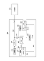
- FIG. 10 is a partially enlarged view of FIG. 9. It is an image figure which shows the operation example of the electrical storage system in the case of the three-day holiday which concerns on 1st Embodiment. It is a block diagram which shows the structural example of the electrical storage system which concerns on 2nd Embodiment.
- FIG. 1 is an explanatory diagram showing an outline of a wireless sensor system 1.
- the wireless sensor system 1 includes a monitoring center 20 and sensor nodes 10a and 10b.
- Each of the sensor nodes 10a and 10b includes a power storage system 100 (see FIG. 2) of the present invention described later.
- the monitoring center 20 collects the measurement results of the surrounding environment at the sensor nodes 10a and 10b, and performs arithmetic processing on the collected measurement results.
- the sensor nodes 10a and 10b wirelessly transmit the measurement results to the monitoring center 20.
- the measurement result includes information detected by the sensor nodes 10a and 10b, for example, information indicating temperature, humidity, CO 2 concentration, vibration, water level, illuminance, voltage, current, sound, image, and the like. included. Further, the measurement result may include a result of determining the presence or absence of a person using an infrared sensor or the like. Furthermore, the sensor nodes 10a and 10b may be stationary devices, or may be wall-mounted devices or devices that are attached to walls.
- the sensor nodes 10a and 10b operate by being supplied with power from an energy harvest (Energy Harvest) power supply, and do not require laying of power supply wiring or the like, thus increasing the degree of freedom in arrangement.
- an energy harvest Energy Harvest
- two sensor nodes 10a and 10b are shown as sensor nodes. However, there may be one sensor node or three or more sensor nodes.
- the sensor node 10a and the sensor node 10b have the same configuration, and in the following description, either one or both are described as the sensor node 10.
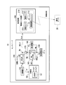
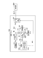
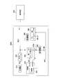
- FIG. 2 is a configuration diagram illustrating a configuration example of the sensor node 10 using the power storage system 100 according to the present embodiment.
- the sensor node 10 is a sensor node installed in a room such as an office, for example, and is a sensor node to which power is supplied by sunlight or indoor light power generation.
- the sensor node 10 acquires environmental information on temperature and humidity, and periodically transmits the environmental information to the monitoring center 20 by radio. For example, the sensor node 10 transmits environmental information to the monitoring center 20 at intervals of 5 minutes.
- the sensor node 10 includes a power storage system 100 that stores the generated power of a solar battery 110 (power generation element) that performs environmental power generation in a storage battery, and a load device 200 that is fed from the power storage system 100. Is done.
- the load device 200 is, for example, an environment monitoring device 210 that functions as a wireless sensor that operates without wiring or battery replacement.
- the environmental monitoring device 210 includes a temperature sensor 211 that measures the temperature in a room such as an office, and a humidity sensor 212 that measures the humidity in the room.
- the environment monitoring device 210 periodically wirelessly transmits the indoor temperature information measured by the temperature sensor 211 and the indoor humidity information measured by the humidity sensor 212 to the external monitoring center 20 by the wireless communication unit 213.
- the load device 200 when “the load device 200 stops operation”, since the power supply voltage required by the load device 200 cannot be received from the power storage system 100, the load device 200 performs the measurement operation and the communication operation. This means a state where it cannot be performed, and is different from the sleep period (pause period) when the load device 200 performs periodic transmission. Further, when “the load device 200 returns to operation”, the load device 200 temporarily stops its operation due to a power supply voltage drop, and then the power supply voltage required by the load device 200 can be received again from the power storage system 100. This means that the load device 200 is ready to perform the measurement operation and the communication operation.
- the load device 200 operates by receiving power from the power storage system 100, and starts operation when the power supply voltage supplied from the power storage system 100 is, for example, 2.7 V or more. The operation is stopped when the power supply voltage supplied from the power supply becomes 2.5 V or less. In other words, the load device 200 stops operating when the power supply voltage supplied from the power storage system 100 is, for example, 2.5 V or less, and once stopped, the power supply voltage is increased to, for example, 2.7 V or more. Then, the operation is restored again, and has a hysteresis characteristic of 0.2 V with respect to the power supply voltage.
- the temperature sensor 211 and the humidity sensor 212 are configured by a measuring device or a detector according to the usage application of the sensor node 10.
- the temperature sensor 211 and the humidity sensor 212 perform measurement in accordance with the control of the wireless communication unit 213 and output information indicating the obtained measurement result to the wireless communication unit 213.
- the measurement by the temperature sensor 211 and the humidity sensor 212 is performed in accordance with the timing at which the wireless communication unit 213 performs wireless transmission, for example.
- the wireless communication unit 213 encodes and modulates the measurement results input from the temperature sensor 211 and the humidity sensor 212 to generate a transmission signal, and periodically transmits the transmission signal to the monitoring center 20 through wireless communication. Note that most of the power consumption in the environment monitoring device 210 is spent on transmission power when the wireless communication unit 213 performs wireless transmission.
- the wireless communication unit 213 does not have a wireless reception function in order to reduce power consumption.
- the wireless communication unit 213 is not necessarily limited to this, and if desired, the wireless communication unit 213 213 may have a reception function.
- the environment monitoring apparatus 210 shifts to a sleep state (rest period) and reduces power consumption when the wireless communication unit 213 does not perform wireless transmission. For example, when the transmission interval time is set to T1 minutes, the environment monitoring device 210 enters a sleep state for T1 minutes, and returns again after the T1 minutes have elapsed. When returning, the environment monitoring device 210 again acquires temperature and humidity information and wirelessly transmits the information. That is, the environment monitoring device 210 is configured not to acquire temperature and humidity information and wirelessly transmit during sleep.
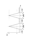
- FIG. 3 is an explanatory diagram showing an aspect of current consumption in the load device 200 according to the present embodiment.
- the horizontal axis indicates time, and the vertical axis indicates the amount of current consumption.
- the load device 200 transmits, for example, every 5 minutes.
- the load device 200 starts a communication operation from time t11 and ends the communication operation at time t13.
- the communication period Tm from time t11 to t13, current flows at a peak value of about the maximum current A2 (several mA) at the time t12.
- a suspension period (sleep period) Ts from time t13 to time t21 has elapsed, and at time t21 after five minutes have elapsed from time t11, the load device 200 starts the communication operation again, and performs communication operation at time t23. finish.
- the communication period Tm from time t21 to time t23 current flows at a peak value of about the maximum current A2 (several mA) at time t22.
- the current flowing from the power storage system 100 to the load device 200 is a current consumption of about the current A1 (several tens of ⁇ A) as an average value.
- the power storage system 100 supplies power to the load device 200 and operates the load device 200.
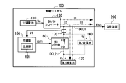
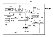
- This power storage system 100 includes a solar battery 110 using an energy harvesting element, a DC / DC converter 120 (DC voltage-DC voltage converter), a first storage battery 130, a second storage battery 140, a switching unit 150, A first switch unit 160 and a voltage detection unit 170 are provided.
- Solar cell 110 is a solar cell for low illuminance, for example, a solar cell that is used at an illuminance of 10,000 (Lux) or less.
- the power generation capacity of the solar cell 110 is about 200 to 500 ( ⁇ W) when the brightness of the lamp is about 200 lux.
- the solar battery 110 charges the first storage battery 130 and the second storage battery 140 and supplies power to the load device 200 during a period when an electric lamp is turned on in an office or the like.
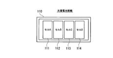
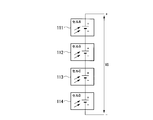
- FIG. 4A and FIG. 4B are explanatory views showing an overview of the solar cell and the connection state of the solar cells according to this embodiment, respectively.
- a solar battery cell A111 on the light-receiving surface side of the solar battery 110, four solar battery cells of a solar battery cell A111, a solar battery cell B112, a solar battery cell C113, and a solar battery cell D114 are planar.
- these four solar cells A111 to D114 are connected in series to obtain a predetermined output voltage Vs.
- 4A and 4B is an example in which four solar cells A111 to four solar cells D114 are connected in series.
- the number of solar cells connected in series is selected so that the voltage Vs output to the DC / DC converter 120 is a voltage at which the DC / DC converter 120 can perform step-up and step-down operations with a predetermined efficiency or higher. Is done.
- the solar cell is a low illuminance dye-sensitized solar cell, it is desirable that the number of solar cells connected in series is, for example, at least 3 or more.
- the input side of the DC / DC converter 120 is connected to the output side of the solar cell 110.
- the output voltage Vs of the solar battery 110 is input to the DC / DC converter 120.
- the DC / DC converter 120 converts the input voltage Vs into a voltage corresponding to the power supply voltage to the load device 200.
- the DC / DC converter 120 is configured with a boost converter device or the like when the output voltage Vs of the solar cell 110 is lower than the voltage required by the load device 200, for example.
- the DC / DC converter 120 outputs the converted voltage to the power supply line DCL1, and charges the first storage battery 130 or the series circuit of the first storage battery 130 and the second storage battery 140.
- the output voltage of the DC / DC converter 120 is controlled so as not to exceed a predetermined upper limit voltage (for example, 3.7 V), so that the charging voltage of the first storage battery 130 is not overcharged.
- a predetermined upper limit voltage for example, 3.7 V
- the DC / DC converter 120 steps down to a voltage corresponding to the power supply voltage to the load device 200.
- the upper limit voltage of the first storage battery 130 is not exceeded.
- the DC / DC converter 120 includes an integrated circuit.
- the DC / DC converter 120 is configured to set the upper limit value of the output voltage by adjusting the resistance value of an external external resistor.
- the first storage battery 130 and the second storage battery 140 are connected in series.
- the first storage battery 130 and the second storage battery 140 are charged by the solar battery 110 and accumulate electric charges.
- the first storage battery 130 is a lithium ion capacitor (LIC), for example, a 40 F (Farad) large capacity lithium ion capacitor having a larger capacity than the second storage battery 140. Note that the 40 F lithium ion capacitor constituting the first storage battery 130 has less leakage current than the second storage battery 140.
- the first storage battery 130 is supplied with the generated power of the solar battery 110 via the DC / DC converter 120 when the first switch unit 160 is in an ON state while the lamp is lit in an office or the like.
- the 1st storage battery 130 is the electric power charged by the 1st storage battery 130, when the solar cell 110 is not generating electric power, or when the electric power generation amount of the solar cell 110 is less than the electric power consumption of the load apparatus 200. Is supplied to the load device 200.
- the first storage battery 130 supplies electric power charged in the first storage battery 130 to the load device 200 when the first switch unit 160 is in an ON state during a period when the lamp is turned off in an office or the like.
- the lithium ion capacitor of the first storage battery 130 is charged to a voltage of, for example, about 2.5V to 3.7V at the time of shipment.
- the second storage battery 140 is a capacitor having a smaller capacity than the capacity of the first storage battery 130, for example, an electric double layer capacitor (EDLC) of 1F (Farad).
- the second storage battery 140 is connected to the first storage battery 130 in series. Further, the electric double layer capacitor constituting the second storage battery 140 has a leakage current larger than that of the lithium ion capacitor of the first storage battery 130.
- the second storage battery 140 is supplied with the generated power of the solar battery 110 via the DC / DC converter 120 when the first switch unit 160 is in an OFF state while the lamp is lit in an office or the like.
- the 2nd storage battery 140 supplies the electric power currently charged by the 2nd storage battery 140 to the load apparatus 200, when a battery value is more than predetermined value.
- the lithium ion capacitor with few leak currents is used as the 1st storage battery 130.
- the second storage battery 140 is a capacitor that is short-circuited at both ends in a normal state and used only for a short time when the operation of the load device 200 is restored, and the maximum voltage to be charged is the first threshold value.
- the voltage is about the difference voltage (0.2 V) from the second threshold, and is used at a very low charging voltage. For this reason, a capacitor having a larger leakage current than the first storage battery 130 can be used for the second storage battery 140.
- the second storage battery 140 has a capacity of a voltage difference between 2.7 V (second threshold voltage) and 2.5 V (first threshold voltage) of the second storage battery 140, and at least one load device 200. The operation is made possible. Thereby, in the electrical storage system 100, it is possible to avoid that the voltage Va of the first storage battery 130 becomes 2.5 V (the first threshold voltage) or less immediately after the first switch unit 160 is connected.
- the capacity of the first storage battery 130 is not limited to 40 F, and is appropriately determined based on the power generation amount of the solar battery 110, the average value of the power consumption of the load device 200, and the time for which the load device 200 is to be continuously driven. Capacitors with a large capacity can be selected.
- the capacity of the second storage battery 140 is not limited to 1F, and is appropriately determined based on the power generation amount of the solar battery 110, the average value of the power consumption of the load device 200, and the time for which the load device 200 is to be restored. Capacitors with a large capacity can be selected.
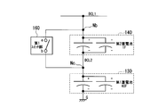
- FIG. 5A and FIG. 5B are configuration diagrams showing the connection configuration of the first storage battery 130 and the second storage battery 140 according to the present embodiment, respectively.
- FIG. 5A shows an example in which the first storage battery 130 and the second storage battery 140 are configured by a single capacitor.
- FIG. 5B shows an example in which the first storage battery 130 and the second storage battery 140 are composed of a plurality of capacitors.
- the first storage battery 130 is configured with a 40F large-capacity lithium ion capacitor
- the second storage battery 140 is configured with a 1F small-capacity electric double layer capacitor.
- the terminal of the positive electrode (+) of the second storage battery 140 is connected to the power supply line DCL1, and the negative electrode ( ⁇ ) terminal of the second storage battery 140 is connected to the positive electrode (+) of the first storage battery 130 via the power supply line DCL2. Connected to the terminal.
- the negative electrode ( ⁇ ) terminal of the first storage battery 130 is connected to the ground G.
- the first switch unit 160 is connected to the second storage battery 140 in parallel.
- the first switch unit 160 short-circuits both ends of the second storage battery 140 in the ON state (closed state), and opens both ends of the second storage battery 140 from the short-circuit state in the OFF state (open state). .
- the terminal a in the first switch unit 160 is connected to the node Nb of the power supply line DCL1, and is connected to the positive electrode (+) terminal of the second storage battery 140 via the node Nb.
- the terminal b in the first switch unit 160 is connected to the node Nc of the power supply line DCL2, and the negative electrode ( ⁇ ) terminal of the second storage battery 140 and the positive electrode (+) of the first storage battery 130 via the node Nc. Is connected to the terminal.
- the 1st switch part 160 is an ON state, ie, when the both ends of the 2nd storage battery 140 are short-circuited, feeding line DCL1 and feeding line DCL2 are connected, and the positive electrode (+) terminal of the 1st storage battery 130 Are directly connected to the feeder line DCL1 via the first switch section 160.
- the first switch unit 160 is in the ON state, the charging voltage Va of the first storage battery 130 is output to the power supply line DCL1.
- the 1st switch part 160 when the 1st switch part 160 is an OFF state, the 1st storage battery 130 and the 2nd storage battery 140 are connected in series. And when the 1st switch part 160 is an OFF state, the voltage Vb of the positive electrode (+) terminal of the 2nd storage battery 140 is output to feeder line DCL1.
- the voltage Vb of the positive electrode (+) terminal of the second storage battery 140 is a charging voltage Vb of a series circuit of the first storage battery 130 and the second storage battery 140, the charging voltage of the second storage battery 140 itself, and the first storage battery 130. Is a voltage obtained by adding the charging voltage Va.
- the voltage Vb of the positive electrode (+) terminal of the second storage battery 140 or “the charging voltage Vb of the series circuit of the first storage battery 130 and the second storage battery 140” is simply referred to as “the second storage battery 140. May be referred to as “voltage Vb”.
- the charging voltage Va of the first storage battery 130 is a voltage of the positive electrode (+) terminal of the first storage battery 130, and this “voltage Va of the positive electrode (+) terminal of the first storage battery 130” or “ “Charge voltage Va” may be simply referred to as “voltage Va of first storage battery 130”.
- FIG. 5A shows an example in which the first storage battery 130 and the second storage battery 140 are configured by a single capacitor.
- the first storage battery 130 and the second storage battery 140 include a plurality of storage batteries. You may comprise with a capacitor. That is, each of the first storage battery 130 and the second storage battery 140 can be configured by an arbitrary number of storage capacitors.
- the first switch unit 160 is turned on or off according to the instruction content of the control signal CNT1 input from the switching unit 150.
- FIG. 2 shows an example in which the first switch unit 160 is configured by a switch using a mechanical contact.
- the switch is a MOSFET (Metal Oxide Semiconductor Field Effect Transistor) or an IGBT (IGBT).
- MOSFET Metal Oxide Semiconductor Field Effect Transistor
- IGBT IGBT
- a semiconductor switch using a semiconductor switching element such as an insulated gate bipolar transistor
- the voltage detection unit 170 is configured by using, for example, a resistance voltage dividing circuit, and detects the voltage Vout of the power supply line DCL1.
- the voltage detection unit 170 outputs the voltage detection signal Vf of the voltage Vout of the power supply line DCL1 to the switching unit 150.
- the voltage detected by the voltage detection unit 170 is the voltage Va of the first storage battery 130 when the first switch unit 160 is in the ON state, and the voltage Vb of the second storage battery 140 when the first switch unit 160 is in the OFF state.
- the switching unit 150 includes a comparison unit 151.
- the comparison unit 151 compares the voltage detection signal Vf of the voltage Vout of the feeder line DCL1 input from the voltage detection unit 170 with predetermined reference voltages Ref1 and Ref2 included in the own unit.
- the switching unit 150 outputs to the first switch unit 160 a control signal CNT1 for turning on / off (opening / closing) the first switch unit 160 according to the comparison result in the comparison unit 151.
- the switching unit 150 When the comparison unit 151 determines that the voltage Vout of the power supply line DCL1 is 2.5 V (first threshold voltage) or less, the switching unit 150 outputs the control signal CNT1 that turns the first switch unit 160 to the OFF state. Output. In addition, the switching unit 150 outputs the control signal CNT1 that turns off the first switch unit 160, and then the voltage Vout of the feeder line DCL1 becomes 2.7 V (second threshold voltage) or higher by the comparison unit 151. When the determination is made, the control signal CNT1 for turning on the first switch unit 160 is output. That is, the switching unit 150 controls the open / close state of the first switch unit 160 with a hysteresis characteristic of 0.2V width between 2.5V and 2.7V.
- the comparison unit 151 compares the voltage detection signal Vf of the voltage Vout of the feeder line DCL1 with a predetermined reference voltage Ref1.
- the reference voltage Ref1 corresponds to a voltage of 2.5 V (first threshold voltage) used when determining that the first storage battery 130 is approaching an overdischarged state.
- Whether the voltage Va of the first storage battery 130 is 2.5 V or less by comparing the voltage detection signal Vf of the feeder line DCL1 with a predetermined reference voltage Ref1 when the first switch unit 160 is ON. Determine whether or not.
- the switching unit 150 outputs the control signal CNT1 to the first switch unit 160 and turns off the first switch unit 160.
- First storage battery 130 and second storage battery 140 are connected in series. Thereby, as for the electrical storage system 100, the charge to the 1st storage battery 130 and the electric power feeding to the load apparatus 200 from the 1st storage battery 130 stop.
- the comparison unit 151 compares the voltage detection signal Vf of the voltage Vout of the feeder line DCL1 with a predetermined reference voltage Ref2 in a state where the first switch unit 160 is OFF.
- This reference voltage Ref2 is a state in which the power storage system 100 stops charging from the solar battery 110 to the first storage battery 130 and feeding from the first storage battery 130 to the load device 200 (hereinafter referred to as feeding from the first storage battery). This corresponds to a voltage of 2.7 V (second threshold voltage) used when determining whether or not to return to the normal state from the stop state.
- the comparison unit 151 compares the voltage detection signal Vf of the feeder line DCL1 with the reference voltage Ref2 in a state where the first switch unit 160 is OFF, thereby determining whether or not the voltage Vb of the second storage battery 140 is 2.7 V or higher. Determine whether. Then, when the voltage Vb of the second storage battery 140 is 2.7 V or higher, the switching unit 150 turns on the first switch unit 160 and short-circuits both ends of the second storage battery 140 so that the first storage battery The positive electrode (+) terminal 130 is directly connected to the power supply line DCL1. Thereby, as for the electrical storage system 100, the charge to the 1st storage battery 130 and the electric power feeding to the load apparatus 200 from the 1st storage battery 130 are restarted.
- the switching unit 150 detects the charging voltage of the second storage battery 140 alone (charging voltage of a predetermined part of the series circuit) by the voltage detection unit 170, and the charging voltage of the second storage battery 140 and the first storage battery 130.
- the total charging voltage charging voltage of the entire series circuit
- both ends of the second storage battery 140 are short-circuited by closing the first switch unit 160. You may do it.
- the switching unit 150 may consider the voltage of the first storage battery 130 as the first threshold value and determine the charging voltage of the entire series circuit using only the storage capacity of the second storage battery 140 alone.
- the switching unit 150 is charged from the solar battery 110 to the series circuit of the first storage battery 130 and the second storage battery 140.
- the charging voltage of the entire series circuit or a predetermined portion is detected, and the charging voltage of the entire series circuit becomes equal to or higher than a predetermined second threshold voltage that is higher than the first threshold voltage,
- the first switch unit 160 may be controlled to be turned on.
- the load device 200 is driven.
- the power storage system 100 is configured so that, for example, the load device 200 can be driven for about 60 hours continuously by the electric power stored in the first storage battery 130.
- the operation of the load device 200 is temporarily stopped due to a decrease in the charging voltage Va of the first storage battery 130 in a state where the power supply from the solar battery 110 is stopped, the power generation of the solar battery 110 starts again.
- the operation of the load device 200 can be restored in about 10 minutes.
- the power storage system 100 once stops the operation of the load device 200 due to the decrease in the charging voltage Va of the first storage battery 130.
- the load device 200 is reduced in a short time according to the power generation amount of the solar cell 110. It is configured to be able to restore the operation.
- the solar cell 110 stops power generation and the load device 200 stops operation and then the solar cell 110 starts power generation again” or “the amount of power generated by the solar cell 110 depends on the load device. If the power generation amount of the solar cell 110 increases or the state where the power generation amount is low continues after the load device 200 stops operating, the solar cell 110 generates power. The case of being in a state may be simply referred to as “when solar cell 110 generates power”.
- the charging voltage Va of the first storage battery 130 is set to 2.5 V (first threshold voltage) so as not to be overdischarged.
- the voltage is not low.
- the storage system 100 stops supplying power from the first storage battery 130 to the load device 200 when the charging voltage of the first storage battery 130 is in a voltage state close to an overdischarge state of 2.5V.
- the load device 200 stops its operation.
- the voltage at which power supply to the load device 200 is started is set to, for example, 2.7 V (second threshold voltage).
- the load device 200 itself returns to operate at a power supply voltage of 2.7 V or higher.
- the charging current that can be supplied from the solar battery 110, which is an energy harvesting element, to the first storage battery 130 is as small as several tens of ⁇ A.
- the load device 200 has a problem that the operation stops for several hours when the first storage battery 130 is recharged.
- the first storage battery 130, the second storage battery 140, and the first switch unit 160 as a switching mechanism are used.
- the power storage system 100 In the normal state where the first storage battery 130 is equal to or higher than the first threshold voltage, the power storage system 100 short-circuits both ends of the second storage battery 140 by the first switch unit 160 and performs charge / discharge using only the first storage battery 130. I am doing so.
- the power storage system 100 stops the supply of power to the load device 200 and sets the first switch unit 160 to the OFF state so that the first The second storage battery 140 is connected to the storage battery 130 in series.
- the solar battery 110 causes a charging current to flow through the series circuit of the first storage battery 130 and the second storage battery 140.
- the charging voltage of the second storage battery 140 rapidly increases due to the charging current from the solar battery 110.
- the charging voltage Vb of the series circuit of the first storage battery 130 and the second storage battery 140 can reach the voltage of 2.7 V necessary for returning the operation of the load device 200 in a short time.
- the electrical storage system 100 can return the load apparatus 200 in a short time (for example, about 10 minutes).
- the power storage system 100 of the present embodiment uses the first storage battery 130 having a large capacity such that the charging time takes several hours depending on the amount of power generated by the solar battery 110, so that the output voltage that supplies power to the load device 200 is used. Vout can be raised quickly. Therefore, in the power storage system 100, for example, when the power generation of the solar battery 110 is stopped and the operation of the load device 200 is temporarily stopped due to a decrease in the voltage Va of the first storage battery 130, the solar battery 110 starts power generation. Then, the operation of the load device 200 can be restored in a short time.
- the power storage system 100 outputs an output voltage Vout that supplies power to the load device 200 when the state where the power generation amount is low after the operation of the load device 200 is stopped in a state where the power generation amount of the solar battery 110 is small. Can be launched quickly. For this reason, in the power storage system 100, when the operation of the load device 200 is temporarily stopped in a state where the power generation amount of the solar cell 110 is small, the operation of the load device 200 is restored in a short time according to the power generation amount of the solar cell 110. be able to.
- the charging voltage Va of the first storage battery 130 decreases to 2.5 V or less before the load device 200 Operation stops again. That is, the operation stop and the operation return of the load device 200 are repeated in a state where the power generation amount of the solar battery 110 is small.
- the load device 200 can continuously perform measurement and communication operation for a certain period of time.
- the first threshold voltage is 2.5 V, but this voltage may be a value equal to or higher than the voltage at which the lithium ion capacitor is not overdischarged. For example, if the voltage at which the lithium ion capacitor is overdischarged is 2.2V, the first threshold voltage may be a voltage exceeding 2.2V, such as 2.3V.
- the second threshold voltage is set to 2.7V so that the charging voltage of the second storage battery 140 is 0.2V.
- the present invention is not limited to this. For example, 2.6V or the like. can do.
- the capacity of the second storage battery 140 may be changed according to the voltage of the second threshold. For example, in the power storage system 100, when the second threshold voltage is 2.6V, the capacity of the second storage battery 140 is set to 2F, and the same amount of charge as when the second threshold voltage is 2.7V can be accumulated. You may do it.
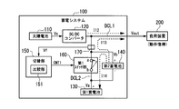
- FIG. 6A and FIG. 6B are explanatory diagrams illustrating a power supply state to the load device 200 when the first switch unit 160 according to the present embodiment is in the ON state.
- the aspect of the electric power feeding to the load apparatus 200 when the 1st switch part 160 is ON is demonstrated.
- the first switch unit 160 is in the ON state, the solar battery 110 is generating power, and the charging voltage Va of the first storage battery 130 exceeds 2.5 V (first threshold).
- first threshold 2.5 V
- DC / DC Converter 120 supplies current I1 to load device 200 to supply power, and also supplies charging current I2 to first storage battery 130 via first switch unit 160.
- the first switch unit 160 is switched from the first storage battery 130.
- the current I3 is supplied to the load device 200 to supply power. That is, when the power generation amount of the solar battery 110 is smaller than the power consumption amount of the load device 200, the first storage battery 130 supplies the power by supplying the current I3 to the load device 200 via the first switch unit 160.
- the first storage battery 130 is connected to the load device 200 via the first switch unit 160.
- a current I3 is supplied to supply power.
- the load device 200 stops the measurement operation and the communication operation, and the current I3 from the first storage battery 130 to the load device 200. No longer flows.
- the switching unit 150 turns the first switch unit 160 to the OFF state.
- the electrical storage system 100 stops the charge to the 1st storage battery 130, and the electric power feeding to the load apparatus 200 from the 1st storage battery 130, and connects the 1st storage battery 130 and the 2nd storage battery 140 in series.
- FIG. 7A and FIG. 7B are explanatory diagrams illustrating a power feeding state from the solar cell 110 to the second storage battery 140 when the first switch unit 160 according to the present embodiment is in an OFF state.
- FIG. 7A and FIG. 7B the aspect of the electric power feeding from the solar cell 110 to the 2nd storage battery 140 and the 1st storage battery 130 when the 1st switch part 160 is OFF is demonstrated.
- FIG. 7A shows a state in which the solar cell 110 is charging the series circuit of the first storage battery 130 and the second storage battery 140 after the first switch unit 160 is turned off, and the load device 200 operates. Indicates a stopped state. Immediately after the first switch unit 160 is turned off, the voltage Vout of the feeder line DCL1 becomes the voltage Vb of the second storage battery 140, but the charging voltage of the second storage battery 140 is initially approximately 0V, The voltage Vb is substantially equal to the charging voltage 2.5V of the first storage battery 130.
- the capacity of the second storage battery 140 is as small as 1F, so the voltage Vb of the second storage battery 140 is the first storage battery 130 of 40F from the solar battery 110. As compared with the case of charging the battery, it is rapidly increased. Then, when the voltage Vb of the second storage battery 140 increases to 2.7 V, the operation of the load device 200 is restored as shown in FIG. 7B, and a current I12 flows from the solar cell 110 to the load device 200. Further, when the power generation amount of the solar battery 110 is smaller than the power consumption amount of the load device 200, the current I13 flows from the second storage battery 140 to the load device 200. As a result, the load device 200 can perform measurement and communication operation.
- the first switch unit 160 shifts from the OFF state to the ON state, and the power storage system 100 returns to the normal state operation shown in FIGS. 6A and 6B. .
- the first switch unit 160 changes from the OFF state to the ON state, the current I14 flows from the second storage battery 140 to the first storage battery 130 via the first switch unit 160, as shown in FIG.
- One storage battery 130 is charged by the electric charge stored in the second storage battery 140.
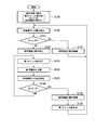
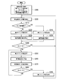
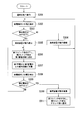
- FIG. 8 is a flowchart showing a processing procedure in the power storage system 100 according to the present embodiment.
- FIG. 8 is a flowchart showing an operation flow in the above-described power storage system 100.
- the flow of the process will be described with reference to FIG.
- step S100 it is assumed that the power storage system 100 is operating in a normal state (step S100). That is, in the power storage system 100, it is assumed that the first switch unit 160 is in the ON state, the voltage Va of the first storage battery 130 exceeds 2.5V, and the load device 200 is operating.
- the voltage detection unit 170 detects the voltage of the power supply line DCL1 (in this case, the voltage Va of the first storage battery 130), and outputs the voltage detection signal Vf to the switching unit 150 (step S105).
- the switching unit 150 determines whether or not the voltage Va of the first storage battery 130 exceeds 2.5 V (first threshold voltage) by comparing the voltage detection signal Vf with a predetermined reference voltage Ref1. (Step S110).
- step S110 when it is determined that the voltage Va of the first storage battery 130 exceeds 2.5V (first threshold voltage) (step S110: Yes), that is, the voltage Va of the first storage battery 130 is When it is not 2.5 V or less, the load device 200 continues to operate (step S115), and the power storage system 100 returns to the process of step S105. Subsequently, the power storage system 100 executes the processing from step S105 onward again.
- first threshold voltage first threshold voltage
- step S110 when it is determined in step S110 that the voltage Va of the first storage battery 130 does not exceed 2.5V (the voltage of the first threshold) (step S110: No), that is, the voltage Va of the first storage battery 130 is When it becomes 2.5V or less, while the load apparatus 200 stops operation
- the load device 200 supplies the power supply voltage (in this case, the first storage battery 130 of the first storage battery 130) supplied from the first storage battery 130 via the feeder line DCL1.
- the device detects that the voltage Va) is 2.5 V or less and stops the measurement and the communication operation by itself.
- the switching unit 150 switches the first switch unit 160 from the ON state to the OFF state (step S130).
- the electrical storage system 100 stops the charge to the 1st storage battery 130, and the electric power feeding to the load apparatus 200 from the 1st storage battery 130, and connects the 1st storage battery 130 and the 2nd storage battery 140 in series.
- the solar cell 110 is generating electric power
- the 2nd storage battery 140 is charged from the solar cell 110 (step S140).
- the voltage detection unit 170 detects the voltage of the power supply line DCL1 (in this case, the voltage Vb of the second storage battery 140), and outputs the voltage detection signal Vf to the switching unit 150 (step S150).
- the switching unit 150 determines whether or not the voltage Vb of the second storage battery 140 is equal to or higher than 2.7 V (second threshold voltage) by comparing the voltage detection signal Vf with a predetermined reference voltage Ref2 (Step S1). S160).
- step S160 when it is determined that the voltage Vb of the second storage battery 140 is not equal to or higher than 2.7 V (second threshold voltage) (step S160: No), the process returns to step S130, and the switching unit 150 The OFF state of the first switch unit 160 is maintained as it is (step S130). Subsequently, the power storage system 100 repeatedly executes the processes after step S140. That is, when the power storage system 100 shifts to a state where power supply from the first storage battery is stopped, the solar battery 110 does not generate power and the solar battery 110 does not charge the second storage battery 140. Since the voltage Vb does not increase, the processing from step S130 to step S160 is repeatedly executed. Even when the second storage battery 140 is charged from the solar battery 110, the processing from step S130 to step S160 is repeatedly executed until the voltage Vb of the second storage battery 140 becomes 2.7 V or higher.
- step S160 When the solar battery 110 generates power, the voltage Vb of the second storage battery 140 increases to 2.7 V or higher, and the switching unit 150 causes the voltage Vb of the second storage battery 140 to be 2.7 V (second threshold value). Voltage) or higher (step S160: Yes), that is, when the voltage Vb of the second storage battery 140 rises to 2.7 V, the operation of the load device 200 is restored (step S170), and the switching unit 150 switches the first switch unit 160 from the OFF state to the ON state (step S175).
- the load device 200 supplies the power supply voltage (in this case, the second storage battery 140) supplied from the second storage battery 140 via the feeder line DCL1.
- the voltage Vb) is detected to be 2.7 V or more by itself and the operation is restored by itself. Thereby, the electrical storage system 100 returns to a normal state.
- the switching unit 150 may delay the timing at which the first switch unit 160 is switched from the OFF state to the ON state in Step S175 by a predetermined time after the operation of the load device 200 is restored. Thereby, the 2nd storage battery 140 can supply the electric power for at least 1 time, when the load apparatus 200 performs a measurement operation and a communication operation. Subsequently, the power storage system 100 returns to the process of step S105, and executes the processes after step S105 again.
- the power storage system 100 charges the first storage battery 130 when power generation by the solar battery 110 is not performed or when the power generation amount of the solar battery 110 is smaller than the power consumption of the load device 200.
- the voltage Va drops to 2.5 V or less
- the discharge from the first storage battery 130 to the load device 200 is stopped.
- the power storage system 100 charges the second storage battery 140 from the solar battery 110 when the solar battery 110 generates power.
- the power storage system 100 can rapidly charge the second storage battery 140 because the capacity of the second storage battery 140 is smaller than the capacity of the first storage battery 130.
- the power storage system 100 can quickly start up the voltage output to the load device 200 using the power charged in the second storage battery 140.
- the operation of the load device 200 whose operation has been temporarily stopped due to a decrease in the voltage value of the first storage battery 130 can be restored in a short time.
- FIG. 9 is an image diagram illustrating an operation example of the power storage system 100 according to the present embodiment.
- the vertical axis indicates the voltage value
- the horizontal axis indicates the elapsed time (h: hour)
- the change characteristics of the output voltage Vout appearing in the power supply line DCL1 are conceptually illustrated.
- a period indicated by “bright” indicates a time zone in which the office room is brightened by illumination or external light
- a period indicated by “dark” indicates that the room in the office is dark at night or when the illumination is turned off.
- the period indicated by “ON” indicates the period when the first switch unit 160 is in the ON state
- the period indicated by “OFF” indicates the period when the first switch unit 160 is in the OFF state. Yes.
- the voltage Vout appearing on the power supply line DCL1 becomes the voltage Va of the first storage battery 130 when the first switch unit 160 is in the ON state, and the voltage Vout of the second storage battery 140 when the first switch unit 160 is in the OFF state.
- the voltage becomes Vb.
- the first switch unit 160 is in the ON state during the period from the elapsed time “0 hour” to the elapsed time “72 hours” and from the elapsed time t41 to the elapsed time “120 hours”.
- the output voltage Vout is indicated by the voltage Va of the first storage battery 130.
- the first switch unit 160 is in the OFF state, and therefore the output voltage Vout of the feeder line DCL1 is indicated by the voltage Vb of the second storage battery 140. .
- the first day is, for example, 24 hours from 8:00 am on the weekend Friday (for example, the time when the room becomes bright in the office or the like) to 8:00 am the next day.
- the second day is 24 hours from 8am on Saturday to 8am on the following day.
- the third day is 24 hours from 8 am on Sunday to 8 am on the following day.
- the fourth day is 24 hours from 8 am on Monday the next week to 8 am on the following day.
- the fifth day is 24 hours from 8am Tuesday morning to 8am the next day.
- the first day (Friday morning 8am to Saturday morning 8am), the fourth day (Monday morning 8am to Tuesday morning 8am), and the fifth day (Tuesday morning) From 8:00 to 8:00 on Wednesday morning, the “light” period and the “dark” period are repeated on a daily basis.
- the “dark” period It is continuous.
- the first switch unit 160 is in the ON state, and the voltage Vout of the power supply line DCL1 (the voltage of the first storage battery 130).
- Va is in a state of about 2.9V.
- the voltage 2.9V of the power supply line DCL1 is supplied as a power supply voltage from the power supply line DCL1 to the load device 200, and the load device 200 is in an operable state.
- the “bright” period in which the office room is brightened by external light (or illumination light) begins.
- the “bright” period starting at the elapsed time “0 hour” continues until the elapsed time t31 after the elapsed time “0 hour”.
- the solar cell 110 begins to hit light and the power generation of the solar cell 110 is started, charging of the first storage battery 130 from the solar cell 110 is started, and the power supply line DCL1
- the voltage Vout begins to rise.
- the voltage Vout of the feeder line DCL1 becomes the voltage Va of the first storage battery 130.
- the voltage Va of the first storage battery 130 gradually increases, and at time t31, the voltage Va of the first storage battery 130 reaches the maximum value Vmax.
- a “dark” period in which the office room becomes dark begins.
- the “dark” period starting from the elapsed time t31 continues until the elapsed time “72 hours” after the elapsed time t31.
- the power generation of the solar cell 110 is stopped, and the charging from the solar cell 110 to the first storage battery 130 is stopped.
- the measurement and communication operation of the load device 200 are periodically repeated, whereby the charge accumulated in the first storage battery 130 gradually decreases, and the voltage of the first storage battery 130 is reduced. Va gradually decreases.
- the “dark” period continues from the elapsed time t31, through the elapsed time “24 hours” on the second day, and the elapsed time “48 hours” on the third day, to the elapsed time “72 hours” on the third day. To do.
- the voltage Va of the first storage battery 130 gradually decreases, but in the “dark” period, the voltage Va of the first storage battery 130 is 2.5V. Therefore, the first switch unit 160 maintains the ON state. Further, during the “dark” period, the voltage Va of the first storage battery 130 exceeds 2.5 V, and thus the load device 200 continues to operate.
- the power storage system 100 charges the first storage battery 130 from the solar battery 110 by Friday (first day) on weekdays, And the third day), the load device 200 is operated using the electric power stored in the first storage battery 130.
- the voltage of the first storage battery 130 decreases to 2.5 V or less, and the “bright” period starts immediately after the elapsed time “72 hours”. For this reason, at the storage elapsed time “72 hours”, the voltage Va of the first storage battery 130 decreases to 2.5 V or less, the load device 200 stops operating, and the first switch unit 160 is turned off. And when the 1st switch part 160 will be in an OFF state, the 2nd storage battery 140 is connected to the 1st storage battery 130 in series.
- the charging voltage of the second storage battery 140 is 0 V when the first switch unit 160 is turned off, the voltage Vb of the second storage battery 140 (more precisely, the first storage battery 130 and the second storage battery 140 is The charging voltage (2.5 V) of the first storage battery 130 appears as it is in the charging voltage Vb) of the series circuit.
- the “bright” period starts immediately after the elapsed time “72 hours”, light starts to hit the solar cell 110, and the solar cell 110 starts power generation and starts charging the second storage battery 140.
- the second storage battery 140 having a small capacity is rapidly charged by the solar battery 110, and the voltage Vb of the second storage battery 140 rises to 2.7 V at an elapsed time t41 10 minutes (min) after the start of charging. . That is, when charging the second storage battery 140 from the solar battery 110, the charging voltage Vb of the second storage battery 140 is about 40 times that when charging the first storage battery 130 with a large capacity from the solar battery 110. Ascend at a speed of. For this reason, the voltage Vb of the second storage battery 140 increases to 2.7 V after 10 minutes (min) from the start of charging.
- the first switch unit 160 shifts from the OFF state to the ON state, whereby the power storage system 100 shifts to the normal state.
- the first switch unit 160 is turned on, and the voltage Va of the first storage battery 130 appears in Vout of the feeder line DCL1.
- the voltage Va of the 1st storage battery 130 changes by repeating the period of "bright” and "dark". From the fourth day onward, the first storage battery 130 gradually stores the amount of power consumed on the next Saturday and Sunday.
- FIG. 10 is a partially enlarged view of FIG. FIG. 10 is an enlarged view of a region H surrounded by a broken-line circle in FIG.
- the first switch unit 160 is turned off, and the second storage battery 140 and the first storage battery 130 are connected in series.
- the solar cell 110 starts to hit the solar cell 110, and the solar cell 110 starts charging the series circuit of the second storage battery 140 and the first storage battery 130.
- the voltage Vb of the small-capacity second storage battery 140 increases rapidly, and reaches 2.7 V at the elapsed time t41.
- the voltage Va of the large-capacity first storage battery 130 hardly changes between the elapsed time “72 hours” and the elapsed time t41 (strictly speaking, the voltage Va of the second storage battery 140 increases by about 1 / Increase by a voltage of 40).
- the first switch unit 160 is turned on (the second storage battery 140 is short-circuited), so the voltage Vb of the second storage battery 140 and the voltage Va of the first storage battery 130 are the same voltage.
- the voltage Va is shown to be lower than the voltage Vb after the elapsed time t41, but in reality, the voltage Va and the voltage Vb are The same voltage.
- the voltage Va of the first storage battery 130 starts to decrease from the elapsed time t31 and is just 2.5 V at the elapsed time “72 hours”.
- the voltage Va of the first storage battery 130 may reach 2.5 V in the middle of the third day in the case of three consecutive holidays. This is because the continuous drive capability of the load device 200 required for the sensor node 10 is set to drive continuously for 60 hours.
- FIG. 11 is an image diagram showing an operation example of the power storage system 100 in the case of three consecutive holidays according to the present embodiment.
- the vertical axis indicates the voltage value
- the horizontal axis indicates the elapsed time (h)
- the voltage Va of the first storage battery 130 and the voltage Vb of the second storage battery 140 appear on the feeder line DCL ⁇ b> 1.
- the change characteristics of are conceptually illustrated.
- FIG. 11 is different from FIG. 10 in that the first day to the third day are holidays (three consecutive holidays), and the elapsed time “0 hour” from the first day to the elapsed time “72 hours” from the third day. The point that the “dark” period lasts is different.
- the voltage Va of the first storage battery 130 decreases to 2.5V. That is, the voltage Va of the first storage battery 130 decreases to 2.5 V at a time point t32 before the elapsed time “72 hours” on the third day. Then, at the elapsed time t32, when the voltage Va of the first storage battery 130 reaches 2.5V, the load device 200 stops its operation. Further, at this elapsed time t32, the first switch unit 160 is turned off, and the second storage battery 140 is connected to the first storage battery 130 in series.
- the second storage battery 140 is not charged from the solar battery 110, and the first storage battery 130 in this period Tk.
- the charging voltage (2.5V) appears on the power supply line DCL1 as it is.
- the solar cell 110 begins to hit light, and the solar cell 110 starts power generation. In this case, the operation of the load device 200 can be recovered in a short time.
- the power storage system 100 when the voltage Va of the first storage battery 130 is lower than a predetermined threshold voltage (a voltage equal to or higher than the first threshold), the communication time interval of the load device 200 may be increased. As a result, the power storage system 100 supplies the first storage battery 130 to the load device 200 when the solar cell 110 is not generating power or when the power generation amount of the solar cell 110 is less than the power consumption of the load device 200. The amount of power to be reduced can be reduced. For this reason, the electrical storage system 100 can lengthen the period which supplies electric power to the load apparatus 200.
- a predetermined threshold voltage a voltage equal to or higher than the first threshold
- the switching unit 150 may determine the second threshold voltage by looking at the potential difference (charging voltage) of the second storage battery 140. That is, the switching unit 150 detects the charging voltage of the second storage battery 140 alone (charging voltage of a predetermined part of the series circuit) by the voltage detection unit 170, and the charging voltage of the second storage battery 140 and the first storage battery 130.
- both ends of the second storage battery 140 are short-circuited by closing the first switch unit 160. You may do it.
- the switching unit 150 may consider the voltage of the first storage battery 130 as the first threshold value and determine the charging voltage of the entire series circuit using only the storage capacity of the second storage battery 140 alone. Then, when both ends of the second storage battery 140 are opened from the short-circuited state by the first switch unit 160, the switching unit 150 is charged from the solar battery 110 to the series circuit of the first storage battery 130 and the second storage battery 140.
- the first switch unit 160 may be controlled to be turned on.
- the power storage system 100 of the present embodiment includes the solar battery 110 (power generation element) that performs environmental power generation, and the first storage battery that is supplied with power from the generated power of the solar battery 110 and supplies power to the load device 200.
- the solar battery 110 power generation element
- the first storage battery that is supplied with power from the generated power of the solar battery 110 and supplies power to the load device 200.
- 130 a second storage battery 140 having a capacity smaller than that of the first storage battery 130 and connected in series to the first storage battery 130, and connected in parallel to the second storage battery 140. In the closed state, both ends of the second storage battery 140 are connected.
- a first switch unit 160 that short-circuits and opens the short-circuit state of the second storage battery 140 in the open state and a switching unit 150 that controls the open / close state of the first switch unit 160 are provided.
- the switching unit 150 is switched to the first storage battery 130.
- the charging voltage Va of the first storage battery 130 becomes 2.5 V or less, the first switch unit 160 is opened.
- both ends of the second storage battery 140 are opened from the short-circuit state by the first switch unit 160 and the series circuit of the first storage battery 130 and the second storage battery 140 is charged from the solar battery 110,
- the charging voltage of the whole series circuit (the charging voltage of the first storage battery 130 and the second storage battery 140 (charging voltage of the entire series circuit) Vb) or a predetermined part is detected, and the charging voltage of the entire series circuit is If it becomes more than a high voltage 2.7V (voltage of a predetermined second threshold value) than the voltage of the first threshold value, the first switch unit 160 controls to the closed state.
- the second storage battery 140 having a small capacity is connected in series to the first storage battery 130, and the first switch unit 160 is connected in parallel to the second storage battery 140.
- the first switch unit 160 short-circuits both ends of the second storage battery 140 when closed, and opens the short-circuit state of the second storage battery 140 when open.
- the open / close state of the switching unit 150 and the first switch unit 160 is controlled.
- the switching part 150 is when the both ends of the 2nd storage battery 140 are short-circuited by the 1st switch part 160, and electric power feeding is performed to the load apparatus 200 via the 1st switch part 160 from the 1st storage battery 130.
- the charging voltage Va of the first storage battery 130 is compared with 2.5 V (the first threshold voltage).
- the switching unit 150 sets the charging voltage Va of the first storage battery 130 to 2.5 V (the first threshold value). Voltage) or less, the first switch unit 160 is opened, and the short-circuited state at both ends of the second storage battery 140 is opened.
- the switching unit 150 for example, when the short-circuit state of the second storage battery 140 is released and power is supplied from the solar battery 110 to the series circuit of the first storage battery 130 and the second storage battery 140, for example, When the charging voltage (charging voltage of the entire series circuit) with the first storage battery 130 and the second storage battery 140 is detected and the charging voltage becomes 2.7 V (a predetermined second threshold voltage) or more, the first switch The both ends of the 2nd storage battery 140 are short-circuited by making the part 160 into a closed state.
- the electrical storage system 100 when the solar cell 110 (power generation element) generates electric power, the operation of the load device 200 can be restored in a short time. Further, in the power storage system 100, the charging voltage of the second storage battery 140 having a small capacity can be increased to a voltage of 2.7 V (second threshold voltage) or more in a short time because the charging voltage is increased in a short time. For this reason, the power storage system 100 can restore the operation of the load device 200 in a short time. In a normal state, the second storage battery 140 is short-circuited by the first switch unit 160, and both the positive electrode and the negative electrode have the same potential as that of the positive electrode of the first storage battery 130.
- the power storage system 100 can restore the operation of the load device 200 in a short time.
- capacitance of the 1st storage battery 130 is the average value of the electric power generation amount of the solar cell 110 (electric power generation element), the power consumption of the load apparatus 200 which supplies electric power from the 1st storage battery 130, It is set based on the time for which the load device 200 is continuously driven by the power stored in the storage battery 130, and the capacity of the second storage battery 140 is the power generation amount of the solar battery 110 and the average value of the power consumption of the load device 200. And the time from when the operation of the load device 200 is stopped due to the decrease in the charging voltage Va of the first storage battery 130 until the power is generated by the solar cell 110 and the operation of the load device 200 is restored. .
- the power generation amount of the solar battery 110 (power generation element) and the consumption of the load device 200 are determined when the capacity of the first storage battery 130 that supplies power to the load device 200 is determined.
- the capacity of the first storage battery 130 is determined based on the average value of the power and the time during which the load device 200 is continuously driven by the power stored in the first storage battery 130.
- the capacity of the second storage battery 140 when determining the capacity of the second storage battery 140 having a small capacity, the amount of power generated by the solar battery 110, the average power consumption of the load device 200, and the operation after the load device 200 stops operating The capacity of the second storage battery 140 is determined based on the time until the battery 110 generates power and restores the operation of the load device 200.
- the load device 200 can be continuously driven for a desired time by the electric power stored in the first storage battery 130. Moreover, in the electrical storage system 100, after the operation
- the first storage battery 130 is a type of capacitor that has a smaller leakage current than the second storage battery 140.
- the first storage battery 130 is a capacitor that holds electric power for a long time, and in order not to waste the stored electric power, the first storage battery 130 has a leakage current. Fewer capacitors are used.
- the second storage battery 140 is a capacitor that is used only for a short time after the operation of the load device 200 stops and until the solar cell 110 generates power and restores the operation of the load device 200, and is charged.
- the maximum voltage is 0.2 V (the difference voltage between the first threshold value and the second threshold value), and is used only at a low charging voltage.
- a capacitor having a larger leakage current than the first storage battery 130 can be used as the second storage battery 140.
- the 1st storage battery 130 can hold
- the power storage system 100 includes a DC / DC converter 120 that converts the output voltage Vs of the solar battery 110 (power generation element) into a predetermined voltage and supplies power to the first storage battery 130 and the second storage battery 140,
- the DC / DC converter 120 controls the output voltage so that the charging voltage Va of the first storage battery 130 does not exceed a predetermined upper limit voltage (for example, 3.7 V).
- the DC / DC converter 120 is connected to the output side of the solar cell 110 (power generation element).
- the DC / DC converter 120 converts the output voltage Vs of the solar battery 110 into a voltage corresponding to the power supply voltage supplied to the load device 200.
- the DC / DC converter 120 supplies power to the first storage battery 130 when the first switch unit 160 is in a closed state by the converted voltage.
- the DC / DC converter 120 Power is supplied to the series circuit with the two storage batteries 140.
- the DC / DC converter 120 controls the output voltage so as not to exceed a predetermined upper limit voltage (for example, 3.7 V) so that the first storage battery 130 is not overcharged.
- the electrical storage system 100 can convert the output voltage Vs of the solar cell 110 (power generation element) into a voltage that allows the load device 200 to operate.
- the DC / DC converter 120 can prevent the first storage battery 130 from being overcharged.
- a lithium ion capacitor is used as the large-capacity first storage battery 130.
- the large-capacity first storage battery 130 needs to hold a charge for a long time.
- a lithium ion capacitor with a small leakage current is used for the first storage battery 130.
- the 1st storage battery 130 can be hold
- the power storage system 100 of the present invention increases the length of the load device 200 even when the solar cell 110 stops power generation or when the power generation amount of the solar cell 110 is smaller than the power consumption of the load device 200. Can be operated over time.
- FIG. 12 is a configuration diagram illustrating a configuration example of a power storage system 100A according to the present embodiment.
- the power storage system 100A shown in FIG. 12 includes a point where a second switch unit 180 is newly added, a point where the switching unit 150 is changed to a switching unit 150A, and a load device 200. Is different from the load device 200A.
- the load device 200A is different from the load device 200 in that the load device 200A is configured to start the operation as it is when supplied with a power supply voltage exceeding 2.5 V, which is an input power supply specification.
- Other configurations are the same as those of the power storage system 100 shown in FIG. For this reason, the same code
- the second switch unit 180 connects or opens the power supply line DCL1 and the power supply line DCL10 by setting the ON state or the OFF state according to the instruction content of the control signal CNT2 input from the switching unit 150A. . That is, when the second switch unit 180 is turned on, the power supply line DCL1 and the power supply line DCL10 are connected, and power is supplied from the power storage system 100A to the load device 200A.
- the switching unit 150A includes a comparison unit 151A.
- the voltage Va of the first storage battery 130 is 2.5 V (the first threshold voltage) or less when the first switch unit 160 is ON.
- the first storage battery 130 and the second storage battery 140 are connected in series by outputting the control signal CNT1 to the first switch section 160 and turning off the first switch section 160. Thereby, power storage system 100A shifts to a state where power supply from the first storage battery is stopped.
- the switching unit 150A compares the voltage detection signal Vf with a predetermined reference voltage Ref3 to determine whether or not the voltage Va of the first storage battery 130 exceeds a predetermined third threshold voltage.
- the third threshold voltage may be a voltage of 2.5 V or more and 2.7 V (second threshold voltage) or less, for example, the first threshold voltage.
- the voltage may be the same as 5 V, or may be 2.55 V, 2.6 V, or a voltage higher than the first threshold voltage of 2.5 V.
- the switching unit 150A When the voltage Va of the first storage battery 130 is equal to or lower than the third threshold voltage, the switching unit 150A outputs the control signal CNT2 to the second switch unit 180, turns the second switch unit 180 off, The supply of power to the load device 200A is stopped. In addition, when the voltage Va of the first storage battery 130 exceeds the third threshold voltage, the switching unit 150A outputs the control signal CNT2 to the second switch unit 180 and turns on the second switch unit 180. Thus, power is supplied to the load device 200A. Thereby, in power storage system 100A, power can be supplied to load device 200A only when charging voltage Va of first storage battery 130 exceeds the voltage of the third threshold.
- the comparison unit 151A sets the first switch unit 160 to the ON state and sets the second storage battery 140 Both ends are short-circuited, and the first storage battery 130 is directly connected to the feeder line DCL1. Thereby, power storage system 100A returns to the normal state from the power supply stop state from the first storage battery.
- the load device 200A does not need to determine the magnitude of the power supply voltage supplied from the power supply line DCL1, and the second switch unit 180 is turned on, and the power storage system 100A.
- the operation can be started immediately.
- the first switch unit 160 and the second switch unit 180 are turned on at the same timing by setting the third threshold voltage to 2.5 V (the same voltage as the first threshold voltage). Can be turned off. That is, when the first switch unit 160 is in the ON state, the second switch unit 180 is in the ON state, and when the first switch unit 160 is in the OFF state, the second switch unit 180 is in the OFF state.
- FIG. 13 is a first flowchart showing a processing procedure in the power storage system 100A according to the present embodiment.
- FIG. 13 is a flowchart showing an operation flow in the above-described power storage system 100A.
- the flow of the processing will be described with reference to FIG.
- step S200 it is assumed that the power storage system 100A is operating in a normal state (step S200). That is, in the power storage system 100A, the first switch unit 160 is in the ON state, the voltage Va of the first storage battery 130 exceeds 2.5V, the second switch unit 180 is in the ON state, and the load device 200A operates. Suppose that it is inside.
- the voltage detection unit 170 detects the voltage of the power supply line DCL1 (in this case, the voltage Va of the first storage battery 130), and outputs the voltage detection signal Vf to the switching unit 150A (step S205). Subsequently, the switching unit 150A determines whether or not the voltage Va of the first storage battery 130 exceeds the third threshold voltage by comparing the voltage detection signal Vf with a predetermined reference voltage Ref3 (step S210). .
- step S210 When it is determined in step S210 that the voltage Va of the first storage battery 130 exceeds the third threshold voltage (step S210: Yes), the switching unit 150A is ON when the second switch unit 180 is in the OFF state. In the case of the ON state, the ON state is continued as it is (step S215). Thereby, power storage system 100A supplies power to load device 200A to operate load device 200A (step S220). Subsequently, the power storage system 100A proceeds to the process of step S240.
- step S210 when it is determined in step S210 that the voltage Va of the first storage battery 130 does not exceed the voltage of the third threshold (step S210: No), the switching unit 150A is in the case where the second switch unit 180 is in the ON state. Is switched to the OFF state, and in the OFF state, the OFF state is continued as it is (step S225). Thereby, power storage system 100A stops the supply of electric power to load device 200A, and stops the operation of load device 200A (step S230). Subsequently, the power storage system 100A proceeds to the process of step S240.
- the switching unit 150A determines whether or not the voltage Va of the first storage battery 130 exceeds 2.5V (first threshold voltage) by comparing the voltage detection signal Vf with a predetermined reference voltage Ref1. (Step S240).
- step S240 when it is determined that the voltage Va of the first storage battery 130 exceeds 2.5 V (first threshold voltage) (step S240: Yes), the process returns to step S205, and the power storage system 100A Steps S205 and subsequent steps are repeatedly executed.
- step S240 when it is determined in step S240 that the voltage Va of the first storage battery 130 does not exceed 2.5V (first threshold voltage) (step S240: No), that is, the voltage of the first storage battery 130 is 2.
- the switching unit 150A switches the first switch unit 160 from the ON state to the OFF state (step S250).
- power storage system 100A shifts to a state where power supply from the first storage battery is stopped, and first storage battery 130 and second storage battery 140 are connected in series.
- the solar cell 110 generates power
- the second storage battery 140 is charged from the solar cell 110 (step S260).
- the voltage detection unit 170 detects the voltage of the power supply line DCL1 (in this case, the voltage Vb of the second storage battery 140), and outputs the voltage detection signal Vf to the switching unit 150A (step S270).
- the switching unit 150A determines whether or not the voltage Vb of the second storage battery 140 is equal to or higher than 2.7 V (second threshold voltage) by comparing the voltage detection signal Vf with a predetermined reference voltage Ref2 (Step S1). S280).
- step S280 when it is determined that the voltage Vb of the second storage battery 140 is not equal to or higher than 2.7 V (step S280: No), the process returns to step S250, and the switching unit 150A switches the first switch unit 160 to the OFF state. This is maintained as it is (step S250), and then, the power storage system 100A repeatedly executes the processes after step S260.
- step S280 Yes
- the switching unit 150A determines that the voltage Vb of the second storage battery 140 is equal to or higher than 2.7 V (second threshold voltage) (step S280: Yes)
- the switching unit 150A turns off the first switch unit 160.
- the state is switched to the ON state (step S290).
- the power storage system 100A returns to the process of step S100, and executes the processes after step S205 again.
- the power storage system 100A can quickly load the load device 200 when the solar cell 110 generates power after the operation of the load device 200A temporarily stops due to the decrease in the charging voltage Va of the first storage battery 130. The operation of 200A can be restored. Also, the power storage system 100A can supply power to the load device 200A only when the voltage exceeding the third threshold voltage at which the load device 200A can operate can be supplied.
- FIG. 14 is a second flowchart showing a processing procedure in the power storage system 100A according to the present embodiment.
- FIG. 14 is an example in the case where the third threshold voltage and the first threshold voltage are set to the same voltage of 2.5 V in the power storage system 100A.
- the flowchart shown in FIG. 14 is different from FIG. 13 in the processing steps S210A to 230A surrounded by the broken lines in FIG.
- Other processing steps are the same as those in the flowchart shown in FIG. For this reason, the same code
- step S205 voltage detection unit 170 detects the voltage of power supply line DCL1 (in this case, voltage Va of first storage battery 130), and outputs voltage detection signal Vf to switching unit 150A. . Subsequently, the switching unit 150A determines whether or not the voltage Va of the first storage battery 130 exceeds 2.5 V (the voltage of the third threshold and the first threshold) (step S210A).
- step S210A when it is determined that the voltage Va of the first storage battery 130 exceeds 2.5V (step S210A: Yes), the switching unit 150A is in the ON state when the second switch unit 180 is in the OFF state. In the case of switching and ON state, the ON state is continued as it is (step S215A). Thereby, power storage system 100A supplies power to load device 200A to operate load device 200A (step S220A). Subsequently, the power storage system 100A returns to the process of step S205, and repeatedly executes the processes of step S210A and the subsequent steps.
- step S210A when it is determined in step S210A that the voltage Va of the first storage battery 130 does not exceed 2.5V (step S210A: No), that is, the charging voltage Va of the first storage battery 130 is 2.5V or less.
- the switching unit 150A turns off the second switch unit 180 (step S225A). Thereby, power storage system 100A stops the supply of power to load device 200A and stops the operation of load device 200A (step S230A). Subsequently, the switching unit 150A proceeds to the process of step S250.
- the subsequent processing after step S250 is the same as the processing shown in FIG.
- the first switch unit 160 and the second switch unit 180 have the same timing. Can be turned on and off. That is, when the first switch unit 160 is in the ON state, the second switch unit 180 can be in the ON state, and when the first switch unit 160 is in the OFF state, the second switch unit 180 can be in the OFF state. For this reason, compared with the case of FIG. 13, the control in the switching unit 150A is simplified.
- the power storage system 100A further includes the second switch unit 180 that connects or opens the power storage system 100A and the load device 200A, and the switching unit 150A determines the charging voltage Va of the first storage battery 130 as follows.
- the second switch unit 180 When the charging voltage Va of the first storage battery 130 exceeds the third threshold voltage as compared to the third threshold voltage which is 2.5 V (first threshold voltage) or higher, the second switch unit 180 is connected.
- the second switch unit 180 When the charging voltage Va of the first storage battery 130 is equal to or lower than the third threshold voltage, the second switch unit 180 is opened.
- the switching unit 150A has a state in which the charging voltage Va of the first storage battery 130 exceeds the third threshold voltage and can supply necessary power from the first storage battery 130 to the load device 200A.
- the second switch unit 180 is connected to supply power to the load device 200A.
- the switching unit 150A is switched to the second switch unit 180. Is opened, and the supply of power to the load device 200A is stopped.
- the power storage system 100A stops the supply of power to the load device 200A by opening the second switch unit 180 and is necessary for the load device 200A. In a state where a large amount of power can be supplied, the power can be supplied to the load device 200A with the second switch unit 180 connected.
- the voltage of the third threshold is set to 2.5 V (the same voltage as the voltage of the first threshold), and the switching unit 150A closes the first switch unit 160 and sets the second storage battery.
- the second switch unit 180 is connected, and the first switch unit 160 is opened and both ends of the second storage battery 140 are released from the short-circuited state. Leave it open.
- the switching unit 150A is necessary for the load device 200A from the first storage battery 130 in a state where the first switch unit 160 is closed and both ends of the second storage battery 140 are short-circuited.
- the second switch unit 180 is connected to supply power to the load device 200A.
- the switching unit 150A opens the first switch unit 160 and opens both ends of the second storage battery 140 from the short-circuited state, that is, from the solar battery 110 (power generation element) to the first storage battery 130 and the second storage battery 150A.
- the second switch unit 180 is opened.
- the power storage system 100A places the second switch unit 180 in the connected state when the first switch unit 160 is in the closed state, and opens the second switch unit 180 when the first switch unit 160 is in the open state. Can be. That is, the power storage system 100A can control the open / close state of the first switch unit 160 and the open / close state of the second switch unit 180 at the same timing.
- the electrical storage system of this invention is not limited only to the above-mentioned illustration example, Of course, in the range which does not deviate from the summary of this invention, a various change can be added.
- the power generation element may be any power generation element that can perform environmental power generation.
- energy harvesting other than light is, for example, power generation by heat, vibration, wind power, radio waves, and the like.
- the environment monitor device 210 includes the temperature sensor 211 and the humidity sensor 212, but the environment monitor device 210 includes the temperature sensor 211 and the humidity sensor 212. Any one sensor may be provided.
- the environment monitoring device 210 may include a sensor that detects information related to other environments. Examples of other environmental information include illuminance, CO 2 concentration, vibration, water level, voltage, current, sound, and image.
- the power storage systems 100 and 100A can be used as a power source for opening and closing a door and a power source for an electrical switch.
- FIG. 15 is a configuration diagram illustrating a configuration example of a power storage system 300 according to the present embodiment.
- the power storage system 300 supplies power to the load device 400 and causes the load device 400 to operate.
- the load device 400 is, for example, an environment monitoring device that functions as a wireless sensor that operates without wiring or battery replacement.
- the environmental monitoring device includes a temperature sensor that measures the temperature in a room such as an office and a humidity sensor that measures the humidity in the room.
- the load device 400 operates by receiving power supply from the power storage system 300, starts operation when the power supply voltage supplied from the power storage system 300 is, for example, 5.2 V or more, and is supplied from the power storage system 300. The operation is stopped when the power supply voltage becomes 2.5 V or less.
- Each voltage value mentioned above is an example, and is not limited to this.
- the voltage value according to the storage battery used for the electrical storage system 300 and the voltage value according to the use of the electrical storage system 300 may be sufficient.
- the power storage system 300 includes a solar battery 310 using an energy harvesting element, a DC / DC converter 320 (DC voltage-DC voltage converter), a first storage battery 330, and a second storage battery 340. , A switching unit 350, a first switch unit 360, a voltage detection unit 370, and a second switch unit 380.
- Solar cell 310 is a solar cell for low illuminance, for example, a solar cell used at an illuminance of 10,000 (Lux) or less.
- the solar cell 310 is configured so that a plurality of solar cells arranged on the light receiving surface side are connected in series and a predetermined output voltage Vs is obtained.
- the input side of the DC / DC converter 320 is connected to the output side of the solar cell 310.
- the DC / DC converter 320 converts the voltage Vs input from the solar cell 310 into a voltage corresponding to the power supply voltage to the load device 400.
- the output side of the DC / DC converter 320 is connected to the power supply line DCL1. Power is supplied to the load device 400 through the power supply line DCL1.
- the DC / DC converter 320 is configured by a boost converter device or the like.
- the DC / DC converter 320 controls the output voltage so that the charging voltage of the first storage battery 330 does not exceed a predetermined upper limit voltage.
- 1st switch part 360 turns ON or OFF between the positive electrode (+) terminal of the 1st storage battery 330, and electric supply line DCL1.
- the terminal a of the first switch unit 360 is connected to the power supply line DCL1 through the voltage detection unit 370 and is connected to the positive electrode (+) terminal of the second storage battery 340.
- the terminal b of the first switch unit 360 is connected to the positive electrode (+) terminal of the first storage battery 330 and to the terminal f of the second switch unit 380.
- the first storage battery 330 is charged by the power generated by the solar battery 310 and supplies power to the load device 400.
- the first storage battery 330 is a large-capacity capacitor, for example, a 40 F (Farad) lithium ion capacitor (LIC).
- the negative electrode ( ⁇ ) terminal of the first storage battery 330 is connected to the ground GND.
- the positive (+) terminal of the first storage battery 330 is connected to the terminal b of the first switch unit 360 and to the terminal f of the second switch unit 380. Since the first storage battery 330 needs to store electric charge for a long time, a lithium ion capacitor with a small leakage current is used.
- capacitance of the 1st storage battery 330 is not limited to 40F, An appropriate capacity
- the first storage battery 330 is charged to a voltage of about 2.5 V to 3.7 V, for example, at the time of shipment.
- the second storage battery 340 is a capacitor having a smaller capacity than the capacity of the first storage battery 330, for example, an electric double layer capacitor (EDLC) of 1F (farad).
- the positive electrode (+) terminal of the second storage battery 340 is connected to the power supply line DCL1 via the voltage detection unit 370 and is also connected to the terminal a of the first switch unit 360.
- the negative electrode ( ⁇ ) terminal of the second storage battery 340 is connected to the common terminal d of the second switch unit 380.
- capacitance of the 2nd storage battery 340 is not limited to 1F, suitably based on the electric power generation amount of the solar cell 310, the average value of the power consumption of the load apparatus 400, and the time which the load apparatus 400 wants to return. Capacitors with a large capacity can be selected.
- the second switch unit 380 selectively connects the negative electrode ( ⁇ ) terminal of the second storage battery 340 to the ground GND side and the positive electrode (+) terminal side of the first storage battery 330.
- the common terminal d of the second switch unit 380 is connected to the negative ( ⁇ ) terminal of the second storage battery 340.
- the terminal e of the second switch unit 380 is connected to the ground GND.
- the terminal f of the second switch unit 380 is connected to the positive electrode (+) terminal of the first storage battery 330 and to the terminal b of the first switch unit 360.
- a state in which the common terminal d and the terminal e of the second switch unit 380 are connected is referred to as a state in which the second switch unit 380 selects the ground GND side.
- the state where the common terminal d and the terminal f of the second switch unit 380 are connected is referred to as a state where the second switch unit 380 selects the first storage battery 330 side.
- the voltage detector 370 is provided to detect the overdischarge voltage of the first storage battery 330. That is, the lithium ion capacitor constituting the first storage battery 330 has a lower limit voltage, and when the battery is overdischarged to this lower limit voltage, the cell is deteriorated.
- the voltage detection unit 370 detects a voltage corresponding to the charging voltage of the first storage battery 330 so that the lithium ion capacitor constituting the first storage battery 330 is not overdischarged to the lower limit voltage.
- the voltage detection unit 370 detects the voltage Vout of the feeder line DCL1, and outputs the voltage detection signal Vf to the switching unit 350, thereby detecting the voltage corresponding to the overdischarge voltage of the first storage battery 330. Yes.
- the voltage detection unit 370 is configured using, for example, a resistance voltage dividing circuit.
- the switching unit 350 controls the first switch unit 360 and the second switch unit 380 according to the detection voltage of the voltage detection unit 370.
- the switching unit 350 includes a comparison unit 351.
- the comparison unit 351 compares the voltage detection signal Vf from the power supply line DCL1 input from the voltage detection unit 370 with the predetermined first threshold voltage Ref1 and second threshold voltage Ref2 included in the comparison unit 351.
- the first threshold voltage Ref1 is a threshold voltage at which the voltage Vout of the feeder line DCL1 decreases from the normal state and the load device 400 stops operating.
- the first threshold voltage Ref1 is set according to the lower limit voltage of the lithium ion capacitor constituting the first storage battery 330.
- the lower limit voltage of the lithium ion capacitor is, for example, about 2V
- the first threshold voltage Ref1 is, for example, 2.5V
- the second threshold voltage Ref2 is a threshold voltage when the voltage Vout of the feeder line DCL1 rises from the state where the load device 400 stops operating and returns to the normal state.
- the second threshold voltage Ref2 is a voltage higher than the first threshold voltage Ref1 by a voltage corresponding to the hysteresis voltage.
- the hysteresis voltage is, for example, 2.7V
- the switching unit 350 In the normal state, the switching unit 350 outputs the control signal CNT1 for turning on the first switch unit 360, and the control signal CNT2 for selecting the ground GND side by the second switch unit 380.
- the normal state is a state in which the first storage battery 330 and the second storage battery 340 are charged by the generated power of the solar battery 310 and power is mainly supplied from the first storage battery 330 to the load device.
- the voltage Vout of the power supply line DCL1 is changed from the voltage in the normal state (for example, 3V) to the first threshold voltage Ref1 (for example, based on the voltage detection signal Vf input from the voltage detection unit 370.
- the switching unit 350 determines that the voltage has dropped to 2.5 V) or less. When determining in this way, the switching unit 350 outputs the control signal CNT1 for turning the first switch unit 360 OFF, and outputs the control signal CNT2 for selecting the second switch unit 380 to the first storage battery 330 side. To do.
- the 1st storage battery 330 and the 2nd storage battery 340 switched from parallel connection to series connection, and voltage Vout of feeder line DCL1 added the charge voltage of the 2nd storage battery 340, and the charge voltage of the 1st storage battery 330 Become a voltage. Further, the load device 400 stops operating.
- the first storage battery 330 and the second storage battery 340 are connected in parallel immediately after the first switch section 360 is in the OFF state and the second switch section 380 is selected on the first storage battery 330 side (also referred to as a fast startup state). Therefore, the voltage Vout of the feeder line DCL1 is about twice the first threshold voltage Ref1. With subsequent power generation restart of the solar cell 310, the voltage Vout of the feeder line DCL1 increases. When the voltage Vout of the feeder line DCL1 rises to the second threshold voltage Ref2 (5.2V), the operation of the load device 400 is first restored.
- the second threshold voltage Ref2 5.2V
- the switching unit 350 determines that the voltage Vout of the power supply line DCL1 has increased to the second threshold voltage Ref2, outputs a control signal CNT1 that turns on the first switch unit 360, and sets the second switch unit 380 to the ground.
- a control signal CNT2 to be selected on the GND side is output.
- the 1st storage battery 330 and the 2nd storage battery 340 switch from a serial connection to a parallel connection.
- the switching unit 350 has a hysteresis characteristic with a width of 2.7 V between the first threshold voltage Ref1 (2.5 V) and the second threshold voltage Ref2 (5.2 V), and the first switch unit 360.
- the second switch unit 380 is controlled.
- FIG. 15 shows an example in which the first switch unit 360 and the second switch unit 380 are configured by switches using mechanical contacts.
- the switch may include a semiconductor switch using a semiconductor switching element such as a MOSFET (Metal Oxide Semiconductor Field Effect Effect Transistor) or an IGBT (Insulated Gate Bipolar Transistor).
- MOSFET Metal Oxide Semiconductor Field Effect Effect Transistor
- IGBT Insulated Gate Bipolar Transistor
- FIG. 16A and FIG. 16B are explanatory diagrams illustrating power supply states in each switch state in the power storage system according to the present embodiment.
- FIG. 16A is an explanatory diagram when the first switch unit 360 is turned on and the second switch unit 380 is in a state of selecting the ground GND side. In this state, the terminal a and the terminal b of the first switch unit 360 are connected, and the common terminal d and the terminal e of the second switch unit 380 are connected.
- the positive electrode (+) terminal of the first storage battery 330 is connected to the power supply line DCL1 via the first switch unit 360, and the negative electrode ( ⁇ ) terminal of the first storage battery 330 is connected to the ground GND.
- the positive electrode (+) terminal of the second storage battery 340 is connected to the power supply line DCL1, and the negative electrode ( ⁇ ) terminal of the second storage battery 340 is connected to the ground GND through the second switch unit 380. Therefore, the first storage battery 330 and the second storage battery 340 are connected in parallel between the feeder line DCL1 and the ground GND.
- the first storage battery 330 and the second storage battery 340 are charged by the generated power of the solar battery 310, and the discharge currents Ia3 and Ia4 are supplied from the first storage battery 330 and the second storage battery 340 to the load device 400. Supply power.
- the first storage battery 330 and the second storage battery 340 are connected in parallel between the feeder line DCL1 and the ground GND, depending on the generated power from the solar battery 310 and the operation state of the load device 400.
- the first storage battery 330 and the second storage battery 340 are charged and discharged.
- capacitance of the 1st storage battery 330 is larger than the capacity
- FIG. 1st storage battery 330 which mainly charges / discharges the electric power generated from the solar cell 310.
- the load device 400 stops operating, and the switching unit 350 turns off the first switch unit 360 and The 2 switch unit 380 is in a state of selecting the first storage battery 330 side.
- FIG. 16B is an explanatory diagram when the first switch unit 360 is set to the OFF state and the second switch unit 380 is set to the state where the first storage battery 330 side is selected.
- this state high-speed startup state
- the terminal a and the terminal b of the first switch unit 360 are cut off, and the common terminal d and the terminal f of the second switch unit 380 are connected.
- the positive electrode (+) terminal of the first storage battery 330 is connected to the negative electrode ( ⁇ ) terminal of the second storage battery 340 via the second switch unit 380.
- the first storage battery 330 and the second storage battery 340 are switched from the parallel connection to the series connection between the power supply line DCL1 and the ground GND, and the voltage Vout of the power supply line DCL1 is about the first threshold voltage Ref1 (2.5V). Doubled.
- the current Ib flows from the solar battery 310 to the series circuit of the first storage battery 330 and the second storage battery 340, and charging to the first storage battery 330 and the second storage battery 340 is performed. Be started. As a result, the voltage Vout of the feeder line DCL1 further increases.
- the capacity (for example, 1F) of the second storage battery 340 is smaller than the capacity (for example, 40F) of the first storage battery 330. For this reason, when the charging from the solar battery 310 to the second storage battery 340 is started, the charging voltage of the second storage battery 340 rapidly increases. Since the voltage Vout of the power supply line DCL1 is an added value of the charging voltage of the first storage battery 330 and the charging voltage of the second storage battery 340, the voltage Vout of the power supply line DCL1 is rapidly increased by the increase of the charging voltage of the second storage battery 340. To rise.
- the switching unit 350 includes the first switch unit as illustrated in FIG. 16A. 360 is turned on, and the second switch unit 380 is in a state of selecting the ground GND side. As a result, the first storage battery 330 and the second storage battery 340 are switched from serial connection to parallel connection, and power is mainly supplied again from the first storage battery 330 to the load device 400.
- the power storage system 300 is in a normal state. Return to the operation.
- the switching unit 350 has a hysteresis characteristic with a width of 2.7 V between the first threshold voltage Ref1 (2.5 V) and the second threshold voltage Ref2 (5.2 V), and the first switch unit 360 and the second switch unit 380 are controlled. For this reason, stable operation can be maintained.
- FIG. 17 is an explanatory diagram of switch control in the power storage system 300 according to the present embodiment.
- the horizontal axis indicates time
- the vertical axis indicates the detection voltage of the voltage detection unit 370.
- the power generation operation of the solar cell 310 is stopped in a normal state at time t0.
- the first switch unit 360 is in an ON state and the second switch unit 380 is in a state of selecting the ground GND side.
- the first storage battery 330 and the second storage battery 340 are discharged, and the detection voltage of the voltage detection unit 370 decreases as shown in FIG.
- the load device 400 stops operating.
- the first switch unit 360 is turned off, the second switch unit 380 is in a state of selecting the first storage battery 330 side, and the first storage battery 330 and the second storage battery 340 are connected between the power supply line DCL1 and the ground GND.
- the voltage Vout of the power supply line DCL1 is connected in series, and is approximately twice the first threshold voltage Ref1 (2.5V).
- the detection voltage of the voltage detection unit 370 rises to the second threshold voltage Ref2 (5.2 V) or more at time t3, the operation of the load device 400 is restored and the first switch unit 360 is turned on, and the second switch The unit 380 enters the state of selecting the ground GND side, and returns to the normal operation.
- the detection voltage of the voltage detection unit 370 gradually increases after time t3. To go.
- the first storage battery 330 and the small-capacity second storage battery 340 are arranged in series between the power supply line DCL1 and the ground GND in the high-speed startup state. Is done.
- the power storage system 300 can restore the operation of the load device 400 whose operation has been temporarily stopped due to a decrease in the voltage value of the first storage battery 330 in a short time after the power generation of the solar cell 310 is resumed.
- FIG. 18 is a flowchart illustrating a processing procedure in the power storage system 300 according to the present embodiment.
- the power storage system 300 is operating in a normal state (parallel connection) (step S301). That is, in the power storage system 300, the first switch unit 360 is in the ON state, the second switch unit is in the state of selecting the ground GND side, the voltage Vout of the feeder line DCL1 exceeds 2.5V, and the load device Assume that 400 is in operation.
- step S302 the voltage detection unit 370 detects the voltage Vout of the power supply line DCL1 and outputs the voltage detection signal Vf to the switching unit 350 (step S302).
- the switching unit 350 determines whether or not the detection voltage of the voltage detection unit 370 is equal to or lower than the first threshold voltage Ref1 (2.5 V) (step S303).
- step S303 when it is determined that the detection voltage of the voltage detection unit 370 is not equal to or lower than the first threshold voltage Ref1 (2.5V) (step S303: No), the load device 400 continues to operate (step S304).
- the power storage system 300 returns to the process of step S302. Subsequently, the power storage system 300 executes the processing from step S302 onward again.
- step S303 when it is determined in step S303 that the voltage Vout of the power supply line DCL1 is equal to or lower than the first threshold voltage Ref1 (2.5 V) (step S303: Yes), the load device 400 stops operating (step S305). Then, the power storage system 300 proceeds to the process of step S306.
- step S306 the switching unit 350 switches the first switch unit 360 from the ON state to the OFF state, and switches the second switch unit 380 to a state of selecting the first storage battery 330 side.
- the first storage battery 330 and the second storage battery 340 are connected in series between the power supply line DCL1 and the ground GND.
- the solar cell 310 is generating electric power, the charge to the series circuit of the 1st storage battery 330 and the 2nd storage battery 340 is performed from the solar cell 310 (step S307).
- the voltage detection unit 370 detects the voltage Vout of the power supply line DCL1, and outputs the voltage detection signal Vf to the switching unit 350 (step S308).
- the switching unit 350 determines whether or not the detection voltage of the voltage detection unit 370 is equal to or higher than the second threshold voltage Ref2 (5.2V) (step S309). If it is determined in step S309 that the detection voltage of the voltage detection unit 370 is not equal to or higher than the second threshold voltage Ref2 (5.2V) (step S309: No), the process returns to step S306, and the switching unit 350
- the first switch unit 360 is maintained in the OFF state, and the second switch unit 380 is maintained in the state in which the first storage battery 330 side is selected (step S306). Subsequently, the power storage system 300 repeatedly executes the processes after step S306.
- step S306 When power generation from the solar battery 310 resumes, a charging current flows through the series connection of the first storage battery 330 and the second storage battery 340, and the voltage Vout of the feeder line DCL1 increases.
- step S309 When it is determined that the voltage Vout of the power supply line DCL1 has risen to the second threshold voltage Ref2 (5.2 V) or more (step S309: Yes), the operation of the load device 400 returns (step S310), and the switching unit 350 Switches the first switch unit 360 from the OFF state to the ON state, and switches the second switch unit 380 to the state of selecting the ground GND side (step S311). Thereby, the electrical storage system 300 returns to a normal state (parallel connection). Subsequently, the power storage system 300 returns to the process of step S302, and executes the processes after step S302 again.
- the power storage system 300 of the present embodiment includes a power generation element (for example, the solar battery 310) that performs environmental power generation, the power supply line DCL1 that supplies power to the load device 400, and power generation of the power generation element via the power supply line.
- the first storage battery 330 that is charged with power and supplies power to the load device, the second storage battery 340 having a smaller capacity than the first storage battery, and the first storage battery and the second between the feeder line and the ground (GND)
- GFD feeder line and the ground
- Switch units (first switch unit 360, second switch unit 380), a voltage detection unit 370 that detects a voltage at which the first storage battery is overdischarged, and a switch unit that is controlled according to the detection voltage of the voltage detection unit.
- a switching unit 350 for comparing the first threshold voltage Ref1 to be compared with the voltage when the detection voltage of the voltage detection unit is lowered and the voltage when the detection voltage of the voltage detection unit is increased.
- the switching unit compares the detection voltage of the voltage detection unit with the first threshold voltage, and the detection voltage of the voltage detection unit is When the voltage drops below the first threshold voltage, the switch unit is set in a series connection state, and when the switch unit is set in a series connection state, the switching unit sets the detection voltage of the voltage detection unit to the second threshold voltage. When the detection voltage of the voltage detection unit becomes equal to or higher than the second threshold voltage, the switch unit is set in a parallel connection state.
- the operation of the load device can be restored in a short time.
- FIG. 19 is a configuration diagram illustrating a configuration example of a power storage system 300A according to the present embodiment.
- the position of the voltage detection unit 370A is different from the position of the voltage detection unit 370 of the first embodiment.
- Other configurations are the same as those in the first embodiment, and the same components are denoted by the same reference numerals, and redundant description is omitted.
- the voltage detection unit 370 detects a voltage between the ground GND and the power supply line DCL1 and outputs the voltage to the switching unit 350.
- the voltage detection unit 370 ⁇ / b> A detects the voltage between the ground GND and the positive electrode (+) terminal of the first storage battery 330 and outputs it to the switching unit 350.
- the first threshold voltage Ref1 is set according to the lower limit voltage of the lithium ion capacitor constituting the first storage battery 330.
- the first threshold voltage Ref1 is a threshold voltage when the first switch unit 360 is in an ON state and the second switch unit 380 is in a state of selecting the ground GND side. At this time, since the first switch unit 360 is in the ON state, the voltage between the ground GND and the power supply line DCL1 is equal to the voltage between the ground GND and the positive electrode (+) terminal of the first storage battery 330.
- the first threshold voltage Ref1A in the case of the second embodiment is, for example, according to the lower limit voltage of the lithium ion capacitor constituting the first storage battery 330, similarly to the first threshold voltage Ref1 in the case of the first embodiment. Set to 2.5V.
- the second threshold voltage Ref2 is set to a voltage higher than the first threshold voltage Ref1 by a voltage corresponding to the hysteresis voltage.
- the second threshold voltage Ref2 is a threshold voltage when the first switch unit 360 is in an OFF state and the second switch unit 380 is in a state of selecting the first storage battery 330 side.
- the voltage detection unit 370 in the case of the first embodiment detects a voltage between the ground GND and the power supply line DCL1, and this voltage is the charge voltage of the first storage battery 330 and the second storage battery 340. Addition value with charging voltage.
- the voltage detection unit 370A in the case of the second embodiment the voltage between the ground GND and the first storage battery 330 (the charging voltage of the first storage battery 330) is detected, and the second storage battery 340 It becomes a different value by the charge voltage.
- the second threshold voltage Ref2A is added to the first threshold voltage Ref1A by adding a corrected hysteresis voltage corrected according to the capacity of the first storage battery 330 and the capacity of the second storage battery 340. It is set.
- the hysteresis voltage of 2.7 V is a rise in the charging voltage (2.5 V) of the second storage battery 340 immediately after being connected in series and the charging voltage of the second storage battery 340 mainly due to the subsequent power generation of the solar battery 310. Minutes (0.2V).
- the second threshold voltage Ref2A in the present embodiment is expressed by the following equation (1).
- the values of 2.5 V and 0.2 V in the formula (1) are merely examples, and the present invention is not limited thereto.
- the voltage detection unit 370A detects the voltage of the first storage battery 330, the first threshold voltage Ref1A is set according to the lower limit voltage of the first storage battery, The second threshold voltage Ref2A is set to a voltage obtained by adding a corrected hysteresis voltage corrected according to the capacity of the first storage battery and the capacity of the second storage battery 340 to the first threshold voltage.
- the first threshold voltage is set according to the lower limit voltage of the first storage battery, thereby preventing the deterioration of the cells of the first storage battery.
- movement can be stabilized by making the 2nd threshold voltage into the voltage which added the correction
- the electrical storage system of this invention is not limited only to the above-mentioned embodiment, Of course, in the range which does not deviate from the summary of this invention, a various change can be added. It is.
- the example of the solar cell 310 using the environmental power generation element as the power generation element is shown, but the present invention is not limited thereto.
- the power generation element may be any power generation element that can perform environmental power generation.
- energy harvesting other than light is, for example, power generation by heat, vibration, wind power, radio waves, and the like.
- the power storage systems 300 and 300A can be used as a power source for opening and closing a door and a power source for an electrical switch.
- the power consumption of the power source for opening and closing the door and the power source of the electric switch varies depending on the installation environment and usage conditions. Even if it hits, the balance of power generation and power consumption may be negative. In such a case, the power storage systems 300 and 300A can be suitably used.
Landscapes
- Engineering & Computer Science (AREA)
- Power Engineering (AREA)
- Charge And Discharge Circuits For Batteries Or The Like (AREA)
- Secondary Cells (AREA)
Priority Applications (3)
| Application Number | Priority Date | Filing Date | Title |
|---|---|---|---|
| US15/507,067 US9893527B2 (en) | 2014-12-18 | 2015-12-16 | Power storage system and power storage method |
| CN201580045674.6A CN106797134B (zh) | 2014-12-18 | 2015-12-16 | 蓄电系统以及蓄电方法 |
| EP15870004.7A EP3236559B1 (de) | 2014-12-18 | 2015-12-16 | Elektrisches speichersystem und elektrisches speicherverfahren |
Applications Claiming Priority (4)
| Application Number | Priority Date | Filing Date | Title |
|---|---|---|---|
| JP2014256361A JP5857118B1 (ja) | 2014-12-18 | 2014-12-18 | 蓄電システム、及び蓄電方法 |
| JP2014-256361 | 2014-12-18 | ||
| JP2015202668A JP6127108B2 (ja) | 2015-10-14 | 2015-10-14 | 蓄電システム、及び蓄電方法 |
| JP2015-202668 | 2015-10-14 |
Publications (1)
| Publication Number | Publication Date |
|---|---|
| WO2016098802A1 true WO2016098802A1 (ja) | 2016-06-23 |
Family
ID=56126687
Family Applications (1)
| Application Number | Title | Priority Date | Filing Date |
|---|---|---|---|
| PCT/JP2015/085181 Ceased WO2016098802A1 (ja) | 2014-12-18 | 2015-12-16 | 蓄電システム、及び蓄電方法 |
Country Status (4)
| Country | Link |
|---|---|
| US (1) | US9893527B2 (de) |
| EP (1) | EP3236559B1 (de) |
| CN (1) | CN106797134B (de) |
| WO (1) | WO2016098802A1 (de) |
Cited By (1)
| Publication number | Priority date | Publication date | Assignee | Title |
|---|---|---|---|---|
| WO2024138575A1 (zh) * | 2022-12-29 | 2024-07-04 | 深圳市乐祺微电子科技有限公司 | 一种自适应电源管理系统、方法以及储能电源 |
Families Citing this family (18)
| Publication number | Priority date | Publication date | Assignee | Title |
|---|---|---|---|---|
| WO2017163625A1 (ja) * | 2016-03-25 | 2017-09-28 | シャープ株式会社 | 発電システム、パワーコンディショナ、電力制御装置、電力制御方法及び電力制御プログラム |
| JP6536466B2 (ja) * | 2016-04-27 | 2019-07-03 | 株式会社オートネットワーク技術研究所 | 電源装置 |
| US10903655B2 (en) * | 2016-09-27 | 2021-01-26 | I.D. Systems, Inc. | Extended-life asset tracking and sensing power source and management system |
| US10551894B2 (en) * | 2016-11-03 | 2020-02-04 | Microsoft Technology Licensing, Llc | Dynamic power management in a hybrid dual battery system |
| US11153819B2 (en) * | 2017-02-06 | 2021-10-19 | Itron Networked Solutions, Inc. | Battery control for safeguarding lower voltage integrated circuits |
| US10554172B2 (en) * | 2017-03-09 | 2020-02-04 | Alliance For Sustainable Energy, Llc | Illuminated outdoor luminescence imaging of photovoltaic modules |
| US10432130B2 (en) * | 2017-11-28 | 2019-10-01 | GM Global Technology Operations LLC | Electric powertrain and a method of operating the same |
| US10369896B2 (en) | 2017-11-28 | 2019-08-06 | GM Global Technology Operations LLC | Apparatus and method for flexible DC fast charging of an electrified vehicle |
| CN110943504B (zh) * | 2018-09-21 | 2023-09-15 | 精工爱普生株式会社 | 移动设备 |
| CN109449982A (zh) * | 2018-12-07 | 2019-03-08 | 国网山西省电力公司临汾供电公司 | 含多个光伏微电网的配电网的运行维护方法 |
| JP7228790B2 (ja) * | 2019-02-05 | 2023-02-27 | パナソニックIpマネジメント株式会社 | 充電制御装置及び充電制御方法 |
| US12119663B2 (en) | 2019-05-29 | 2024-10-15 | E-Peas S.A. | Method and device for energy harvesting and charging rechargeable energy storage devices |
| US10742242B1 (en) * | 2019-06-05 | 2020-08-11 | Silicon Laboratories Inc. | Apparatus for improving the effective performance of a power source and associated methods |
| US12278508B2 (en) * | 2019-06-17 | 2025-04-15 | Renesas Electronics America Inc. | Single inductor multiple output charger for multiple battery applications |
| DE102019124833A1 (de) * | 2019-09-16 | 2021-03-18 | Enocean Gmbh | Funksensor sowie Verfahren zur Kommunikation mit einem Funksensor |
| US11336101B2 (en) * | 2020-02-03 | 2022-05-17 | GM Global Technology Operations LLC | Adaptive fast-charging of multi-pack battery system in a mobile platform having dual charge ports |
| KR102434036B1 (ko) * | 2021-06-17 | 2022-08-19 | 삼성전자주식회사 | 보조 전원 장치의 수명을 위한 충전 전압 제어 방법 및 이를 수행하는 스토리지 장치 |
| GB202209891D0 (en) * | 2022-07-05 | 2022-08-17 | Lightricity Ltd | Ultra-low power energy harvesting electronic devices with energy efficient backup circuits |
Citations (5)
| Publication number | Priority date | Publication date | Assignee | Title |
|---|---|---|---|---|
| JP2004104942A (ja) * | 2002-09-11 | 2004-04-02 | Murata Mfg Co Ltd | Dc−dcコンバータ |
| JP2006158043A (ja) * | 2004-11-26 | 2006-06-15 | Kitakyushu Foundation For The Advancement Of Industry Science & Technology | 電力制御装置 |
| JP2010022108A (ja) * | 2008-07-09 | 2010-01-28 | Fuji Heavy Ind Ltd | 電源装置 |
| JP2013198297A (ja) * | 2012-03-19 | 2013-09-30 | Fujitsu Ltd | 電源回路 |
| JP2014018011A (ja) * | 2012-07-11 | 2014-01-30 | Nec Toshiba Space Systems Ltd | 電圧トランジェント抑制回路 |
Family Cites Families (16)
| Publication number | Priority date | Publication date | Assignee | Title |
|---|---|---|---|---|
| JPS58183043U (ja) | 1982-05-31 | 1983-12-06 | 三菱電機株式会社 | 表示回路 |
| JPH0429531A (ja) | 1990-05-22 | 1992-01-31 | Nec Eng Ltd | バックアップ電源供給方式 |
| JPH11289675A (ja) | 1998-04-01 | 1999-10-19 | Nec Saitama Ltd | 通信装置の電池切れ延長方法 |
| JP4440406B2 (ja) | 2000-01-26 | 2010-03-24 | 宣夫 芦立 | 電源装置 |
| US7081693B2 (en) * | 2002-03-07 | 2006-07-25 | Microstrain, Inc. | Energy harvesting for wireless sensor operation and data transmission |
| US6590370B1 (en) * | 2002-10-01 | 2003-07-08 | Mti Microfuel Cells Inc. | Switching DC-DC power converter and battery charger for use with direct oxidation fuel cell power source |
| US6949843B2 (en) * | 2003-07-11 | 2005-09-27 | Morningstar, Inc. | Grid-connected power systems having back-up power sources and methods of providing back-up power in grid-connected power systems |
| JP4514143B2 (ja) * | 2005-03-31 | 2010-07-28 | 本田技研工業株式会社 | 電源装置およびその制御方法 |
| CN101156294B (zh) | 2005-04-28 | 2010-12-29 | 罗斯蒙德公司 | 现场设备用的充电系统 |
| US20100060231A1 (en) * | 2006-01-05 | 2010-03-11 | Tpl, Inc. | Method and Apparatus for Energy Harvesting and/or Generation, Storage, and Delivery |
| US8310094B2 (en) * | 2006-01-27 | 2012-11-13 | Sharp Kabushiki Kaisha | Power supply system |
| WO2008064605A1 (fr) * | 2006-11-30 | 2008-06-05 | Beijing Hi-Tech Wealth Investment & Development Co., Ltd | Procédé, appareil et système permettant de fournir de l'énergie à l'aide de cellules photovoltaïques |
| KR101452778B1 (ko) * | 2010-07-27 | 2014-10-22 | 요시후미 다케다 | 축전장치의 충전제어방법 및 방전제어방법 |
| JP5691365B2 (ja) * | 2010-10-07 | 2015-04-01 | ソニー株式会社 | 電力制御装置、電力制御方法、および給電システム |
| JP2013078235A (ja) | 2011-09-30 | 2013-04-25 | Asahi Kasei Corp | リチウムイオンキャパシタを用いた電源装置、及び無線通信機器 |
| KR20130055156A (ko) * | 2011-11-18 | 2013-05-28 | 삼성에스디아이 주식회사 | 배터리 관리 모듈의 오류 통보 장치 및 이를 구비한 에너지 저장 시스템 |
-
2015
- 2015-12-16 WO PCT/JP2015/085181 patent/WO2016098802A1/ja not_active Ceased
- 2015-12-16 US US15/507,067 patent/US9893527B2/en not_active Expired - Fee Related
- 2015-12-16 CN CN201580045674.6A patent/CN106797134B/zh not_active Expired - Fee Related
- 2015-12-16 EP EP15870004.7A patent/EP3236559B1/de not_active Not-in-force
Patent Citations (5)
| Publication number | Priority date | Publication date | Assignee | Title |
|---|---|---|---|---|
| JP2004104942A (ja) * | 2002-09-11 | 2004-04-02 | Murata Mfg Co Ltd | Dc−dcコンバータ |
| JP2006158043A (ja) * | 2004-11-26 | 2006-06-15 | Kitakyushu Foundation For The Advancement Of Industry Science & Technology | 電力制御装置 |
| JP2010022108A (ja) * | 2008-07-09 | 2010-01-28 | Fuji Heavy Ind Ltd | 電源装置 |
| JP2013198297A (ja) * | 2012-03-19 | 2013-09-30 | Fujitsu Ltd | 電源回路 |
| JP2014018011A (ja) * | 2012-07-11 | 2014-01-30 | Nec Toshiba Space Systems Ltd | 電圧トランジェント抑制回路 |
Cited By (1)
| Publication number | Priority date | Publication date | Assignee | Title |
|---|---|---|---|---|
| WO2024138575A1 (zh) * | 2022-12-29 | 2024-07-04 | 深圳市乐祺微电子科技有限公司 | 一种自适应电源管理系统、方法以及储能电源 |
Also Published As
| Publication number | Publication date |
|---|---|
| CN106797134B (zh) | 2018-05-25 |
| EP3236559A4 (de) | 2018-08-01 |
| US20170279275A1 (en) | 2017-09-28 |
| EP3236559A1 (de) | 2017-10-25 |
| EP3236559B1 (de) | 2019-06-12 |
| US9893527B2 (en) | 2018-02-13 |
| CN106797134A (zh) | 2017-05-31 |
Similar Documents
| Publication | Publication Date | Title |
|---|---|---|
| JP5857119B1 (ja) | 蓄電システム、及び蓄電方法 | |
| CN106797134B (zh) | 蓄电系统以及蓄电方法 | |
| JP6122974B2 (ja) | センサノード、及びセンサノードの制御方法 | |
| US9997954B2 (en) | Power storage system and power storage method | |
| US6914411B2 (en) | Power supply and method for controlling it | |
| US10181748B2 (en) | Power storage system and power storage method | |
| JP5857118B1 (ja) | 蓄電システム、及び蓄電方法 | |
| JP6127108B2 (ja) | 蓄電システム、及び蓄電方法 | |
| JP2019030097A (ja) | 電源装置 | |
| WO2015037350A1 (ja) | センサ | |
| JP2021151022A (ja) | 電源装置 |
Legal Events
| Date | Code | Title | Description |
|---|---|---|---|
| 121 | Ep: the epo has been informed by wipo that ep was designated in this application |
Ref document number: 15870004 Country of ref document: EP Kind code of ref document: A1 |
|
| REEP | Request for entry into the european phase |
Ref document number: 2015870004 Country of ref document: EP |
|
| WWE | Wipo information: entry into national phase |
Ref document number: 15507067 Country of ref document: US Ref document number: 2015870004 Country of ref document: EP |
|
| NENP | Non-entry into the national phase |
Ref country code: DE |