WO2016101435A1 - Mécanisme d'impression basé sur un appareil intégré de cerclage et d'impression, machine de cerclage et d'impression à ouverture de session instantanée et son procédé de commande - Google Patents
Mécanisme d'impression basé sur un appareil intégré de cerclage et d'impression, machine de cerclage et d'impression à ouverture de session instantanée et son procédé de commande Download PDFInfo
- Publication number
- WO2016101435A1 WO2016101435A1 PCT/CN2015/075556 CN2015075556W WO2016101435A1 WO 2016101435 A1 WO2016101435 A1 WO 2016101435A1 CN 2015075556 W CN2015075556 W CN 2015075556W WO 2016101435 A1 WO2016101435 A1 WO 2016101435A1
- Authority
- WO
- WIPO (PCT)
- Prior art keywords
- printing
- print head
- slider
- support arm
- instant
- Prior art date
- Legal status (The legal status is an assumption and is not a legal conclusion. Google has not performed a legal analysis and makes no representation as to the accuracy of the status listed.)
- Ceased
Links
Images


Classifications
-
- B—PERFORMING OPERATIONS; TRANSPORTING
- B41—PRINTING; LINING MACHINES; TYPEWRITERS; STAMPS
- B41J—TYPEWRITERS; SELECTIVE PRINTING MECHANISMS, i.e. MECHANISMS PRINTING OTHERWISE THAN FROM A FORME; CORRECTION OF TYPOGRAPHICAL ERRORS
- B41J3/00—Typewriters or selective printing or marking mechanisms characterised by the purpose for which they are constructed
-
- B—PERFORMING OPERATIONS; TRANSPORTING
- B65—CONVEYING; PACKING; STORING; HANDLING THIN OR FILAMENTARY MATERIAL
- B65B—MACHINES, APPARATUS OR DEVICES FOR, OR METHODS OF, PACKAGING ARTICLES OR MATERIALS; UNPACKING
- B65B61/00—Auxiliary devices, not otherwise provided for, for operating on sheets, blanks, webs, binding material, containers or packages
- B65B61/26—Auxiliary devices, not otherwise provided for, for operating on sheets, blanks, webs, binding material, containers or packages for marking or coding completed packages
-
- B—PERFORMING OPERATIONS; TRANSPORTING
- B41—PRINTING; LINING MACHINES; TYPEWRITERS; STAMPS
- B41J—TYPEWRITERS; SELECTIVE PRINTING MECHANISMS, i.e. MECHANISMS PRINTING OTHERWISE THAN FROM A FORME; CORRECTION OF TYPOGRAPHICAL ERRORS
- B41J2/00—Typewriters or selective printing mechanisms characterised by the printing or marking process for which they are designed
- B41J2/005—Typewriters or selective printing mechanisms characterised by the printing or marking process for which they are designed characterised by bringing liquid or particles selectively into contact with a printing material
- B41J2/01—Ink jet
-
- B—PERFORMING OPERATIONS; TRANSPORTING
- B41—PRINTING; LINING MACHINES; TYPEWRITERS; STAMPS
- B41J—TYPEWRITERS; SELECTIVE PRINTING MECHANISMS, i.e. MECHANISMS PRINTING OTHERWISE THAN FROM A FORME; CORRECTION OF TYPOGRAPHICAL ERRORS
- B41J2/00—Typewriters or selective printing mechanisms characterised by the printing or marking process for which they are designed
- B41J2/005—Typewriters or selective printing mechanisms characterised by the printing or marking process for which they are designed characterised by bringing liquid or particles selectively into contact with a printing material
- B41J2/01—Ink jet
- B41J2/135—Nozzles
-
- B—PERFORMING OPERATIONS; TRANSPORTING
- B65—CONVEYING; PACKING; STORING; HANDLING THIN OR FILAMENTARY MATERIAL
- B65B—MACHINES, APPARATUS OR DEVICES FOR, OR METHODS OF, PACKAGING ARTICLES OR MATERIALS; UNPACKING
- B65B27/00—Bundling particular articles presenting special problems using string, wire, or narrow tape or band; Baling fibrous material, e.g. peat, not otherwise provided for
- B65B27/08—Bundling paper sheets, envelopes, bags, newspapers, or other thin flat articles
-
- B—PERFORMING OPERATIONS; TRANSPORTING
- B41—PRINTING; LINING MACHINES; TYPEWRITERS; STAMPS
- B41J—TYPEWRITERS; SELECTIVE PRINTING MECHANISMS, i.e. MECHANISMS PRINTING OTHERWISE THAN FROM A FORME; CORRECTION OF TYPOGRAPHICAL ERRORS
- B41J2202/00—Embodiments of or processes related to ink-jet or thermal heads
- B41J2202/01—Embodiments of or processes related to ink-jet heads
Definitions
- the invention belongs to the field of financial equipment, relates to a device for processing banknotes, and particularly relates to a printing mechanism based on a tie-printing integrated machine, an instant login type printer and a control method thereof.
- the machine is an indispensable device for banks and other financial systems to complete the operation of bundling banknotes. It is mainly used to bundle small stacks of paper money, such as 100 sheets, into a handle.
- tie-bar integrated machines with printing functions in the market.
- the tie-bar mechanism and the printing mechanism are arranged side by side, and the printing mechanism is arranged at the front end of the tie-bar mechanism.
- the information is pre-printed to the tie-tab. Bring it, and then enter the station, this design is huge, just simple combination of the printer and the machine, is twice the ordinary automatic tie machine, and is pre-printed, can not print in real time, information
- the accuracy and timeliness are difficult to grasp, and it is impossible to trace the source effectively.
- the other is the integration of the printing mechanism and the tie-bar mechanism, the printing mechanism is fixed, after the completion of the tie-up, during the withdrawal of the banknotes, by the movement of the banknotes
- the information is unfolded and printed onto the strap.
- the structure is compact in real time, the size is small, but the operator has higher requirements, because the operator must take a straight line motion when picking up the banknote by hand during the printing process, otherwise the printing effect Unclear, and manual operation to achieve uniform linear motion is difficult to control, and requires a beat and a slower speed.
- the technical problem to be solved by the present invention is to provide a printing mechanism based on a jigger printing integrated machine, which adopts a flat structure, and a driving mechanism and an inkjet printing head are arranged side by side on the same frame, and the inkjet printing head is realized by the driving mechanism.
- the movement so that the information is printed on the strap in real time and clearly, and the volume is small, the structure is simple, the printing is fast, and the traceability is easy to trace.
- another technical problem to be solved by the present invention is to provide an instant login type printer and a control method thereof, which adopts an integrated camshaft to sequentially manage the conveying and tightening of the bundled strips and the clamping head.
- the integrated structure of real-time printing and cutting is formed.
- the volume is small, the structure is simple, the printing is fast, the information is real-time, and the traceability is easy to trace.
- the technical solution adopted by the present invention is:
- a printing mechanism based on a tie-printing integrated machine wherein the structure of the integrated machine comprises a semi-embedded banknote positioning inlet channel and a strapping servo mechanism positioned on the frame and surrounding the banknote inlet passage, and is also arranged in the machine Also included on the shelf are inkjet printheads, synchronous drive positioning mechanisms, and associated control systems that have the freedom to move left and right along the frame by means of a synchronous drive positioning mechanism.
- the inkjet print head is positioned on the slider by means of a support arm, and the slider is positioned with the synchronous drive positioning mechanism and has sliding freedom along a guide rail mounted on the frame.
- the synchronous drive positioning mechanism includes an end surface cam positioned on a cam shaft of the strap servo mechanism and a rocker pressed against the end surface cam by a pressure contact spring, the slider abutting, forming and shaking with the free end of the rocker The degree of freedom of the rod to oscillate synchronously.
- the synchronous drive positioning mechanism includes a motor positioned on the frame, a driving wheel coupled to the output shaft of the motor, a matching driven wheel, and a timing belt disposed between the driving wheel and the driven wheel, the slider and the synchronization With positioning connection.
- the synchronous driving positioning mechanism adopts a motor-driven screw wire mother pair or a gear rack pair, and a slider for positioning the inkjet print head is disposed on the timing belt, the nut or the rack.
- the printing mechanism and the strap servo mechanism are disposed on the same rack.
- the printing beat is synchronized with the hot cutting of the strap by means of a synchronous drive positioning mechanism.
- the beneficial effects produced by the above technical solution are as follows: (1) The integrated design of printing and tying in the invention has the advantages of small volume, simple structure, fast printing speed, and no extra tempo; (2) real-time printing is beneficial to (3) The banknote is fixed in the invention, and the inkjet printing component is driven by the synchronous driving positioning mechanism, which has low requirements on the operator and clear printing effect; (4) in a further improvement scheme, The inkjet printing unit can also realize round-trip double-row printing by means of an electromagnet, which increases the amount of information printed.
- the invention also provides an instant login type padding printer, wherein the body structure comprises a semi-embedded banknote positioning inlet channel and a strapping servo mechanism positioned on the frame and surrounding the banknote inlet passage, the servo mechanism comprises : Binding reel positioning, strip conveying and tightening assembly, clamping head and surrounding assembly, press belt tail and hot sticking and cutting assembly, cam shaft between each assembly and drive motor shaft, set in The camshaft constitutes a drive cam of each assembly of the sequence control pair, and an intermediate drive mechanism connected to each of the drive cams; and also disposed on the frame, an inkjet print head, a control circuit and a synchronous drive positioning mechanism
- the synchronous driving positioning mechanism of the inkjet print head comprises an end cam positioned on the cam shaft, a rocker pressed against the end cam by the pressure contact spring, and a slider guide pair slidingly matched with the other end of the rocker. And a support arm disposed on the slider for positioning the inkjet printhead.
- the slider is disposed with a push-pull electromagnet, and the armature of the push-pull electromagnet passes through the slider and is positioned and connected with the support arm of the inkjet print head to form a printing station conversion driving mechanism.
- the support arm includes a lower support arm positioned with the slider and an upper support arm positioned with the inkjet print head, and an open and close electromagnet is disposed on the lower support arm, and the armature rod of the open and close electromagnet is positioned with the upper support arm, A print pitch adjustment mechanism that forms an inkjet printhead.
- the synchronous driving of forming the inkjet print head in the present invention refers to the synchronous control of the inkjet timing point and the inkjet position point during the timing control; the inkjet printhead starting time point controlled by the end cam and the pressure
- the tail end is synchronized with the sticking and cutting time points in the hot and cut assembly, and the ink jet starting point position is synchronized with the position at which the ink jet print head stroke reaches the edge of the strap.
- the integrated camshaft sequentially drives the belt and the left pressure belt assembly, the entrainment assembly, the press head assembly, the cutting assembly and the press belt tail assembly, and drives the inkjet print head when the cutting assembly starts to start.
- the feeding process of the belt, the belt, and the cutting is sequentially performed by means of the camshaft, and the inkjet printing component realizes real-time printing by means of the cam while cutting.
- the invention also provides a control method for instant login of a printer, which is based on the above basic structure to realize the conveying and tightening of the straps, the clamping of the head and the surrounding molding, the pressing of the tail and the scalding and cutting
- the key to synchronous printing of instant messages is: the control steps for instant login of synchronous operation information are as follows:
- the inkjet print head management program After receiving the synchronous start command, the inkjet print head management program reads the CPU memory from the read-only memory module, calls up the operation information, and prints on the corresponding position of the strap.
- the beneficial effects produced by the above technical solution are as follows: (1) The integrated design of printing and tying in the invention has the advantages of small volume, simple structure, fast printing speed, and no extra tempo; (2) real-time printing is beneficial to Tracing the source of the bundle of banknotes; (3) the banknotes are fixed in the invention, and the inkjet printing assembly is driven by the printing cam, which has low requirements on the operator and clear printing effect; (4) in a further improved scheme, the inkjet The printing unit can also realize round-trip double-line printing by means of an electromagnet, which increases the amount of information printed.
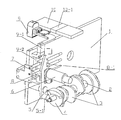
- Figure 1 is a schematic perspective view of the present invention
- FIG. 2 is a schematic structural view of another embodiment of the present invention.
- FIG. 3 is a block diagram showing the structure of the control circuit of the present invention.
- a represents a read-only memory module
- b represents a scratchpad module
- c represents a file module
- k1 represents a first controllable electronic switch
- k2 represents a second controllable electronic switch
- k3 represents a third controllable electronic switch.
- the printing mechanism of the integrated printing machine includes a semi-integrated banknote positioning inlet passage and a strapping servo mechanism positioned on the frame 1 and surrounding the banknote inlet passage.
- the servo mechanism comprises: a strapping disc positioning, a strip conveying and tightening assembly, a clamping head and a surrounding assembly, a press belt tail and a hot sticking and cutting assembly, and a cam is arranged between each assembly and the driving motor shaft A sequence control pair composed of the shaft 2 and the respective assembly drive cams 3, and an intermediate drive mechanism connected to the drive cam; and also disposed on the frame, an inkjet print head 9, a control circuit and a synchronous drive positioning mechanism .
- orientation word "left” appearing in this document refers to the left side of the frame 1, that is, the direction pointing to the lower left in FIG. 1, and the “right” refers to the right side of the bracket 1, that is, the pointing in FIG.
- the reverse of the upper right; "front and rear direction” refers to the direction perpendicular to the plane of the frame 1; it should be understood that these orientation words are established on the basis of the drawings of the specification, and their appearance should not affect the scope of protection of the present invention. .
- the inkjet print head 9 is positioned on the slider 8 by means of a support arm which is positioned with the synchronous drive positioning mechanism and has sliding freedom along the guide rail 7 mounted on the frame 1.
- the guide rail 7 is mounted on the frame 1 in the same direction as the synchronous drive positioning mechanism, and is configured to drive the inkjet print head 9 to move and print synchronously.
- a push-pull electromagnet 6 is disposed on the slider 8, and the armature of the push-pull electromagnet 6 passes through the slider 8 and is positioned with the support arm to form a printing station conversion drive mechanism.
- the push-pull electromagnet 6 is energized, the armature rod is pushed out, and the support arm and the inkjet print head 9 are driven toward The front side is moved a certain distance, and the second line of printing is performed when the inkjet print head 9 returns. Increased the amount of information printed.
- the armature rod drives the inkjet print head 9 on the support arm to have a degree of freedom of movement relative to the frame 1.
- the support arm may also be provided in an upper and lower structure, such as a lower support arm 9-2 positioned with the slider 8 and an upper support arm 9-1 positioned with the inkjet print head, and an electromagnetic opening and closing is provided between the upper and lower support arms.
- a print distance adjustment mechanism that forms an inkjet printhead. The mechanism is configured to adjust the distance of the inkjet printhead from the strap 10-1 for clear printing.
- the body of the opening and closing electromagnet is positioned with the lower support arm 9-2, and the armature rod and the upper support arm 9-1 are positioned.
- the synchronous driving positioning mechanism may adopt a cam, a motor-driven timing belt, a rack and pinion pair, and a ball screw wire mother pair.
- the synchronous drive positioning mechanism comprises an end face cam 4 positioned on the camshaft 2, a rocker 5 pressed against the end face cam 4 by means of a pressure contact spring, and a rocker 5
- a slider 8 rail 7 having a sliding fit at one end, and a support arm provided on the slider 8 for positioning the inkjet print head 9.
- the rocker 5 is hinged on the frame 1 and is provided with a pressing block 5-1 at one end thereof, and is always pressed against the end surface of the end surface cam 4 by means of a pressure contact spring, and oscillates synchronously with the change of the end surface curve of the end surface cam 4, the rocker 5 The other end abuts against the guide rail slider pair, and pushes the slider 8 to the left and right by the wheel 8-1 disposed on the slider to form a right and left movement degree of freedom of the inkjet print head 9.
- a return spring is provided in the structure of the slider 8 to cause the slider to swing in synchronization with the rocker 5.
- Synchronous driving for forming an inkjet print head refers to synchronous control of a print head ejection timing point and an ink ejection position point during timing control; an inkjet print head starting time point controlled by the end surface cam 4 and the pinch tail In synchronization with the sticking and cutting time points in the hot and cut assembly, the ink jet starting point position is synchronized with the position at which the ink jet print head 9 stroke reaches the edge of the strap 10-1.
- the synchronous driving positioning mechanism includes a motor 11 positioned on the frame 1, a driving wheel connected to an output shaft of the motor 11, and a matching device.
- the driven wheel and the timing belt 12 are disposed between the driving wheel and the driven wheel, and the slider 8 is positioned and connected to the timing belt.
- the synchronous drive positioning mechanism employs a motor-driven lead wire pair or a rack and pinion pair, and a slider 8 for positioning the inkjet print head 9 is provided on the core or on the rack.
- the synchronous drive positioning mechanism is driven to move and print to the banknote, and is reset after printing.
- the invention fully utilizes the hot stamping and cutting beats, and adopts an integrated design, has the advantages of simple structure, convenient operation, small volume, and clear printing, and is convenient for the existing replacement.
- an instant login type printer has a semi-embedded banknote positioning inlet passage and a strapping servo mechanism positioned on the frame 1 and surrounding the banknote inlet passage.
- the servo mechanism includes : strip conveying and tightening assembly, clamping head and surrounding assembly, press belt tail and hot sticking and cutting assembly, cam shaft 2 disposed between each assembly and driving motor shaft, and disposed on cam shaft 2 a drive cam 3 constituting each assembly of the sequence control pair, and an intermediate drive mechanism connected to each of the drive cams 3; also disposed on the frame, an ink jet print head 9, a control circuit, and a synchronous drive positioning mechanism
- the synchronous drive positioning mechanism of the inkjet print head comprises an end face cam 4 positioned on the camshaft 2, a rocker 5 pressed against the end face cam 4 by means of the pressure contact spring, and a sliding fit with the other end of the rocker 5
- a slider 8 rail 7 is provided, and a support arm provided on the slider 8 for positioning the inkjet print head
- the rocker 5 is hinged on the frame 1 and is provided with a pressing block 5-1 at one end thereof, and is pressed against the end surface of the end surface cam 4 by means of a pressure contact spring and a pressing block 5-1, and is synchronized with the change of the end surface curve of the end surface cam 4 Swinging, the other end of the rocker 5 abuts against the rail slider pair, and pushes the slider 8 to the right by the wheel 8-1 disposed on the slider.
- the structure of the slider 8 further includes a return spring to drive the sliding.
- the block 8 is reset, and in order to prevent the slider 8 from being snapped back, the end surface cam 4 is provided with a reset curved surface, so that the slider 8 is uniformly returned by the return spring and the reset curved surface on the end face cam 4 to form the left and right of the inkjet print head 9. Freedom of movement.
- a push-pull electromagnet 6 is positioned on the slider 8, and the armature of the push-pull electromagnet 6 passes through the slider 8 and is positioned and connected with the support arm of the inkjet print head 9 to form a printing station conversion drive mechanism.
- the armature rod drives the inkjet print head 9 on the support arm to have a degree of freedom of movement relative to the frame 1.
- the armature rod extends to drive the inkjet print head to move forward a certain distance, and the second line of printing can be performed when the position is returned, thereby increasing the amount of information printed.
- the support arm includes a lower support arm 9-2 positioned with the slider 8 and an upper support arm 9-1 positioned with the inkjet print head, and the lower support arm 9-2 is provided with an opening and closing electromagnet, the opening and closing electromagnet
- the armature rod is positioned with the upper support arm 9-1 to form a print distance adjustment mechanism of the inkjet print head.
- the mechanism is configured to adjust the distance of the inkjet printhead from the strap 10-1 for clear printing.
- Synchronous driving for forming an inkjet print head refers to synchronous control of a print head ejection timing point and an ink ejection position point during timing control; an inkjet print head starting time point controlled by the end surface cam 4 and the pinch tail In synchronization with the sticking and cutting time points in the hot and cut assembly, the ink jet starting point position is synchronized with the position at which the ink jet print head 9 stroke reaches the edge of the strap 10-1.
- the control circuit of the inkjet printhead is an inkjet program controller with a CPU as the core processing unit.
- the inkjet program controller structure includes a read only memory module a having a storage inkjet printhead management software, a temporary register module b and an archive storage module c for random information input.
- a first controllable electronic switch k1 is disposed between the read-only memory module a and the data bus of the CPU, and a third controllable electronic switch k3 is disposed between the register module b and the command output end of the CPU, and the file storage module c and
- a second controllable electronic switch k2 is provided between the data buses of the CPU.
- the inkjet print head management program After receiving the synchronous start command, the inkjet print head management program reads the CPU memory from the read-only memory module a, calls up the operation information, and prints the corresponding position on the strap.
- the random operation information described in step 2 includes: a date, a print time, a banknote type code, a printer code, and/or an operator code.
Landscapes
- Engineering & Computer Science (AREA)
- Mechanical Engineering (AREA)
- Basic Packing Technique (AREA)
Abstract
L'invention concerne un mécanisme d'impression basé sur un appareil intégré de cerclage et d'impression, une machine de cerclage et d'impression à ouverture de session instantanée et son procédé de commande. L'appareil intégré comprend un canal d'entrée de positionnement de cerclage de billets de banque semi-imbriqué, un servomécanisme de bande de cerclage, une tête d'impression à jet d'encre (9), un mécanisme de positionnement à entraînement synchrone et un système de commande correspondant. La tête d'impression à jet d'encre (9) se déplace librement de la gauche vers la droite le long d'un cadre à l'aide du mécanisme de positionnement à entraînement synchrone. Le mécanisme de positionnement à entraînement synchrone comprend une came de face d'extrémité (4) située sur un arbre à cames (2), une barre basculante (5) qui exerce une pression contre la came de face d'extrémité à l'aide d'un ressort de contact, un bloc coulissant (8) et une paire de glissières (7) dans un ajustement coulissant avec une autre extrémité de la barre basculante (5), et un bras support disposé sur le bloc coulissant (8) et utilisé pour positionner la tête d'impression à jet d'encre (9). La configuration intégrée d'impression et de cerclage réalise l'impression en temps réel, facilitant ainsi le tracé de l'origine des liasses de billets de banque cerclées.
Priority Applications (1)
| Application Number | Priority Date | Filing Date | Title |
|---|---|---|---|
| KR1020177017953A KR101981412B1 (ko) | 2014-12-23 | 2015-03-31 | 통합 밴딩 및 프린팅 장치에 기초한 프린팅 메커니즘, 인스턴트-로그인 밴딩 및 프린팅 머신 및 그 제어 방법 |
Applications Claiming Priority (4)
| Application Number | Priority Date | Filing Date | Title |
|---|---|---|---|
| CN201410807189.5A CN104691106B (zh) | 2014-12-23 | 2014-12-23 | 即时登录式扎把打印机及其管控方法 |
| CN201420822286.7U CN204368484U (zh) | 2014-12-23 | 2014-12-23 | 一种基于扎把打印一体机的打印机构 |
| CN201410807189.5 | 2014-12-23 | ||
| CN201420822286.7 | 2014-12-23 |
Publications (1)
| Publication Number | Publication Date |
|---|---|
| WO2016101435A1 true WO2016101435A1 (fr) | 2016-06-30 |
Family
ID=56149052
Family Applications (1)
| Application Number | Title | Priority Date | Filing Date |
|---|---|---|---|
| PCT/CN2015/075556 Ceased WO2016101435A1 (fr) | 2014-12-23 | 2015-03-31 | Mécanisme d'impression basé sur un appareil intégré de cerclage et d'impression, machine de cerclage et d'impression à ouverture de session instantanée et son procédé de commande |
Country Status (2)
| Country | Link |
|---|---|
| KR (1) | KR101981412B1 (fr) |
| WO (1) | WO2016101435A1 (fr) |
Cited By (2)
| Publication number | Priority date | Publication date | Assignee | Title |
|---|---|---|---|---|
| CN108408165A (zh) * | 2018-04-19 | 2018-08-17 | 吉安职业技术学院 | 一种基于弧面凸轮的打码装置 |
| CN111390949A (zh) * | 2020-04-22 | 2020-07-10 | 中国农业大学 | 一种机械爪装置 |
Families Citing this family (1)
| Publication number | Priority date | Publication date | Assignee | Title |
|---|---|---|---|---|
| CN107718028B (zh) * | 2017-11-16 | 2023-07-28 | 河北汇金集团股份有限公司 | 一种自适应任意厚度钞把的夹取机构 |
Citations (7)
| Publication number | Priority date | Publication date | Assignee | Title |
|---|---|---|---|---|
| CN2148037Y (zh) * | 1992-09-05 | 1993-12-01 | 云南省玉溪市新兴装饰配套总厂 | 自动捆钞机 |
| CN2312485Y (zh) * | 1997-09-24 | 1999-03-31 | 姚兵 | 多功能钞票处理器 |
| WO2004012997A1 (fr) * | 2002-08-06 | 2004-02-12 | Glory Kogyo Kabushiki Kaisha | Machine a enliasser des billets de banque |
| CN101437723A (zh) * | 2006-05-04 | 2009-05-20 | 裕一银行安全系统公司 | 打印机式纸钞捆扎器、包括捆扎器的系统及其操作方法 |
| CN102674029A (zh) * | 2011-03-18 | 2012-09-19 | 株式会社东芝 | 纸张处理装置 |
| CN203520446U (zh) * | 2013-11-14 | 2014-04-02 | 中国农业银行股份有限公司南通分行 | 具有捆钞和打印功能的点钞机 |
| CN103754438A (zh) * | 2014-01-23 | 2014-04-30 | 上海古鳌电子科技股份有限公司 | 纸币连续清分扎把盖章打印联体机 |
Family Cites Families (1)
| Publication number | Priority date | Publication date | Assignee | Title |
|---|---|---|---|---|
| JPH1058661A (ja) * | 1996-08-21 | 1998-03-03 | Olympus Optical Co Ltd | インクジェットプリンタ |
-
2015
- 2015-03-31 WO PCT/CN2015/075556 patent/WO2016101435A1/fr not_active Ceased
- 2015-03-31 KR KR1020177017953A patent/KR101981412B1/ko not_active Expired - Fee Related
Patent Citations (7)
| Publication number | Priority date | Publication date | Assignee | Title |
|---|---|---|---|---|
| CN2148037Y (zh) * | 1992-09-05 | 1993-12-01 | 云南省玉溪市新兴装饰配套总厂 | 自动捆钞机 |
| CN2312485Y (zh) * | 1997-09-24 | 1999-03-31 | 姚兵 | 多功能钞票处理器 |
| WO2004012997A1 (fr) * | 2002-08-06 | 2004-02-12 | Glory Kogyo Kabushiki Kaisha | Machine a enliasser des billets de banque |
| CN101437723A (zh) * | 2006-05-04 | 2009-05-20 | 裕一银行安全系统公司 | 打印机式纸钞捆扎器、包括捆扎器的系统及其操作方法 |
| CN102674029A (zh) * | 2011-03-18 | 2012-09-19 | 株式会社东芝 | 纸张处理装置 |
| CN203520446U (zh) * | 2013-11-14 | 2014-04-02 | 中国农业银行股份有限公司南通分行 | 具有捆钞和打印功能的点钞机 |
| CN103754438A (zh) * | 2014-01-23 | 2014-04-30 | 上海古鳌电子科技股份有限公司 | 纸币连续清分扎把盖章打印联体机 |
Cited By (2)
| Publication number | Priority date | Publication date | Assignee | Title |
|---|---|---|---|---|
| CN108408165A (zh) * | 2018-04-19 | 2018-08-17 | 吉安职业技术学院 | 一种基于弧面凸轮的打码装置 |
| CN111390949A (zh) * | 2020-04-22 | 2020-07-10 | 中国农业大学 | 一种机械爪装置 |
Also Published As
| Publication number | Publication date |
|---|---|
| KR101981412B1 (ko) | 2019-05-22 |
| KR20170091132A (ko) | 2017-08-08 |
Similar Documents
| Publication | Publication Date | Title |
|---|---|---|
| US5326179A (en) | Apparatus for producing an information recording card | |
| WO2016101435A1 (fr) | Mécanisme d'impression basé sur un appareil intégré de cerclage et d'impression, machine de cerclage et d'impression à ouverture de session instantanée et son procédé de commande | |
| CN204368484U (zh) | 一种基于扎把打印一体机的打印机构 | |
| CN205112678U (zh) | 可设定打印位置的二维码打印机构 | |
| CN206087430U (zh) | 一种全自动打包机 | |
| CN203727680U (zh) | 打包机机芯 | |
| US12552148B2 (en) | Lamination module for a card processing machine including a system for assisting with peeling of a transfer film | |
| CN214243026U (zh) | 一种薄片类介质快速纠偏传输机构 | |
| TW492943B (en) | A device for braking a machine for processing elements in sheet form | |
| US3416446A (en) | Printing mechanisms for printing on pages of a book | |
| JP2674778B2 (ja) | プリンタ | |
| JP4490534B2 (ja) | 折目側で糸とじされて結合された印刷シートから本ブロックを製造する方法及びこの方法を実施するための装置 | |
| US3223221A (en) | Paper handling mechanism | |
| US8656818B2 (en) | Device for three-sided trimming of products | |
| JP3589677B2 (ja) | 画像記録装置のフィニッシャ | |
| IL30843A (en) | A sophisticated method of printing books whose pages are bound, attached or glued together and a device for carrying out the method | |
| CN105523403B (zh) | 新型模切机叼纸牙及模切机输纸传动机构及输纸传动方法 | |
| JP3539420B2 (ja) | プリンタ | |
| JP4106878B2 (ja) | カッティング装置 | |
| CN215512914U (zh) | 一种胶片居中传动机构 | |
| JP5313724B2 (ja) | シート貼付装置及び貼付方法 | |
| EP4491398A1 (fr) | Module de stratification pour machine de traitement de carte comprenant un système d'aide au décollement d'un film de transfert | |
| JPS5819758Y2 (ja) | カ−ドリ−ダ | |
| CN213923296U (zh) | 一种喷码机的压止结构 | |
| WO2011044719A1 (fr) | Imprimante pour imprimer des images et des caractères sur un support sans papier |
Legal Events
| Date | Code | Title | Description |
|---|---|---|---|
| 121 | Ep: the epo has been informed by wipo that ep was designated in this application |
Ref document number: 15871513 Country of ref document: EP Kind code of ref document: A1 |
|
| NENP | Non-entry into the national phase |
Ref country code: DE |
|
| ENP | Entry into the national phase |
Ref document number: 20177017953 Country of ref document: KR Kind code of ref document: A |
|
| 122 | Ep: pct application non-entry in european phase |
Ref document number: 15871513 Country of ref document: EP Kind code of ref document: A1 |