WO2016101983A1 - Stator segmenté et son procédé de fabrication - Google Patents
Stator segmenté et son procédé de fabrication Download PDFInfo
- Publication number
- WO2016101983A1 WO2016101983A1 PCT/EP2014/079048 EP2014079048W WO2016101983A1 WO 2016101983 A1 WO2016101983 A1 WO 2016101983A1 EP 2014079048 W EP2014079048 W EP 2014079048W WO 2016101983 A1 WO2016101983 A1 WO 2016101983A1
- Authority
- WO
- WIPO (PCT)
- Prior art keywords
- stator
- stator segments
- segments
- segmented
- radially outwardly
- Prior art date
- Legal status (The legal status is an assumption and is not a legal conclusion. Google has not performed a legal analysis and makes no representation as to the accuracy of the status listed.)
- Ceased
Links
Images




Classifications
-
- H—ELECTRICITY
- H02—GENERATION; CONVERSION OR DISTRIBUTION OF ELECTRIC POWER
- H02K—DYNAMO-ELECTRIC MACHINES
- H02K1/00—Details of the magnetic circuit
- H02K1/06—Details of the magnetic circuit characterised by the shape, form or construction
- H02K1/12—Stationary parts of the magnetic circuit
- H02K1/14—Stator cores with salient poles
- H02K1/146—Stator cores with salient poles consisting of a generally annular yoke with salient poles
- H02K1/148—Sectional cores
-
- H—ELECTRICITY
- H02—GENERATION; CONVERSION OR DISTRIBUTION OF ELECTRIC POWER
- H02K—DYNAMO-ELECTRIC MACHINES
- H02K3/00—Details of windings
- H02K3/32—Windings characterised by the shape, form or construction of the insulation
- H02K3/34—Windings characterised by the shape, form or construction of the insulation between conductors or between conductor and core, e.g. slot insulation
- H02K3/345—Windings characterised by the shape, form or construction of the insulation between conductors or between conductor and core, e.g. slot insulation between conductor and core, e.g. slot insulation
-
- H—ELECTRICITY
- H02—GENERATION; CONVERSION OR DISTRIBUTION OF ELECTRIC POWER
- H02K—DYNAMO-ELECTRIC MACHINES
- H02K5/00—Casings; Enclosures; Supports
- H02K5/04—Casings or enclosures characterised by the shape, form or construction thereof
- H02K5/08—Insulating casings
Definitions
- the present invention relates to an electric machine, in particular to an electric motor or a generator which has a segmented stator.
- the present invention more particularly relates to the segmented stator and the method of manufacturing the same.
- Electric machines such as electric motors and generators are commonly known. Electric motors can be used both in industrial and domestic applications. For instance, an electric motor can be used to drive the rotating member of a household appliance.
- An electric motor generally comprises a rotating shaft, a stator, and a rotor which is fixed to the shaft.
- the stator generally comprises a laminated magnetic core which has a plurality of radially inwardly projecting teeth.
- the laminated magnetic core of the stator generally comprises a plurality of windings around the teeth for generating a rotating magnetic field.
- the rotor generally comprises a laminated magnetic core which has a squirrel cage type conductor. The rotor is concentrically disposed into the stator. A small uniform air gap is left between the rotor and the stator.
- stator lamination and the rotor lamination are stamped from the same sheet metal using a die.
- a drawback of this technique is that the slots in the stator lamination are difficult to access when the conducting wires are wound around the teeth. Thus, the slots cannot be completely filled with the winding. Such difficulties put a limitation on the power of the electric motor.
- Another drawback of this technique is that a large amount of waste is produced during the stamping process due to the aforementioned slots and the air gap. The amount of waste is even higher when the rotor is produced from a permanent magnet. The waste generally increases the production cost of the electric machine.
- the stator is manufactured by assembling a plurality of individual stator segments which are formed by stacking a plurality of laminations, each having a yoke, a single tooth, and winding slots on the single tooth.
- the stator segments are respectively provided with windings prior to assembling them.
- the stator segments having the windings are joined with each other.
- the density of the windings can be increased.
- the aforementioned waste can be significantly reduced.
- a drawback of this technique is that there are two wire ends per winding which must be connected to the terminal during the assembly process. Due to the large number of wire ends, there is a risk of confusion. Thus, the connection process becomes complicated and time consuming.
- An objective of the present invention is to provide a segmented stator, an electric machine having the same, and a method of manufacturing the segmented stator which overcomes at least some of the drawbacks of the prior art and which enables a cost effective production, an easy and reliable assemblage, and an improved performance of the electric machine.
- the plurality of stator segments which have been obtained by stacking the plurality of laminations are subsequently arranged into a loop in which all the adjacent stator segments are respectively joined to each other by forming welding joints that are at least partly formed on each of the radially outwardly facing junctions between the adjacent stator segments.
- the stator segments are held tightly together by applying a uniform radially inward force onto the periphery of the segmented stator.
- the waste of sheet metal can be reduced as much as possible. Thereby, the material costs have been comparatively reduced.
- the integrity of the segmented stator can be improved and the stator segments can be joined properly while concurrently reducing the losses due to the eddy currents in as much as possible. Thereby, a proper alignment and a precise gap between the segmented stator and the rotor can be safely established and, thus, the consequential loss of the magnetic flux can also be reduced as much as possible.
- the present invention provides a plurality of alternative techniques for welding the loop of stator segments in order to attain an improved integrity of the segmented stator and reduce the losses due to eddy currents as much as possible.
- the adjacent stator segments are welded only vertically along the radially outwardly facing junctions respectively.
- stator segments are alternatively welded only along one or more than one narrow circumferential contour on the radially outwardly facing surface of the yokes. These contours cross the junctions.
- the thickness of the welding joint along the narrow circumferential contour may range from one to a few laminations.
- a peripheral metal sleeve is circumferentially shrink-fitted around the stator segments, in particular onto the radially outward surfaces of the yokes.
- the welding joints apply a uniform radially inward force onto the periphery of the segmented stator and prevent misalignments/dislocations during the shrink fitting, and thus, the stator segments are held tightly together.
- the sleeve is preferably made from lamination steel and improves the integrity of the segmented stator.
- a peripheral cover is molded over at least the radially outwardly surfaces of the yokes by plastic injection molding operation.
- the welding joints apply a uniform radially inward force onto the periphery of the segmented stator and prevent misalignments/dislocations during the plastic injection molding, and thus, the stator segments are held tightly together.
- the peripheral cover is made from plastic. The plastic peripheral cover improves the integrity of the segmented stators and also provides electrical insulation.
- the peripheral cover is molded so as to also enclose the upper and lower surfaces of the outermost laminations respectively.
- the winding slots of the teeth are respectively covered with insulating materials such as insulators for protecting the electrical conductor of the windings from damage and preventing any short-circuit.
- the insulators are integrally formed with the peripheral cover onto the stator segments by plastic injection molding.
- the insulators have a two-piece structure and are installed onto the teeth respectively.
- the terminal is integrally molded with the peripheral cover.
- the terminal is provided onto the stator segments by sticking, screwing or any other connection method.
- the integrity of the segmented stator is improved by grooves and matching tongues which are formed beforehand into the yokes of the laminations.
- the integrity of the segmented stator is improved by lock holes which are formed beforehand into the laminations.
- the lock holes respectively receive locking extensions from the adjacent laminations.
- some of the laminations comprise welding grooves for receiving the welding joints. Thereby, the welding joints become flush with the surrounding surface of the yokes. Alternatively, the welding joints can be smoothed.
- the plurality of stator segments which are obtained by stacking the plurality of laminations are initially arranged into a loop, and subsequently joined with each other prior to forming the windings.
- the joined stator segments are provided with a terminal.
- an electrical conductor is wound around the tooth in one of the plurality of stator segments, and the winding ends are connected to the terminal.
- the winding process and connection process are serially continued until all stator segments respectively have their own windings that are connected to the terminal.
- the winding and connection processes of the windings can be orderly performed. Thereby, the risk of mixing up and tangling the winding ends is eliminated or reduced as much as possible. Moreover as the winding and connection processes are performed successively, the overall manufacturing process is expedited and the labor costs are comparatively reduced. In addition, the risk of damaging the windings during the joining process has been eliminated as the stator segments are joined prior to the provision of the windings.
- Figure 1 – is a perspective view of a lamination according to an embodiment of the present invention.
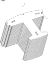
- Figure 2 – is a perspective view of a stator segment which is formed by stacking a plurality of laminations according to an embodiment of the present invention
- Figure 3 – is a perspective view of a plurality of stator segments which are arranged into a loop according to an embodiment of the present invention
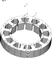
- Figure 4 – is a perspective view of a loop of stator segments which are joined to each other by welding joints according to an embodiment of the present invention
- Figure 5 – is a perspective view of a loop of stator segments which are joined to each other by welding joints according to another embodiment of the present invention
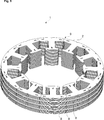
- Figure 6 – is a perspective view of a loop of stator segments which are joined to each other by a metal sleeve which is shrink fitted around the radially outwards surfaces of the yokes according to another embodiment of the present invention
- Figure 7 – is a perspective view of a loop of stator segments which are joined to each other by a plastic peripheral cover which is molded onto the radially outwards surfaces of the yokes, the upper surface of the uppermost lamination, and the lower surface of the lowermost lamination according to another embodiment of the present invention.
- the segmented stator (1) comprises a plurality of stator segments (2).
- Each stator segment (2) has a plurality of stacked laminations (3).
- Each lamination (3) has a yoke (4), a single tooth (5), and winding slots (6) on the tooth (5) (Fig. 1 to 7).
- the plurality of stator segments (2) are arranged into a loop in which all the adjacent stator segments (2) are respectively joined to each other by welding joints (7, 8) which are at least partly formed on each of the radially outwardly facing junctions (9) between the adjacent stator segments (2).
- the present invention also provides an electric machine (not shown), in particular an electric motor (not shown) or a generator (not shown) which comprises the segmented stator (1) according to the present invention.
- the electric machine also comprises a rotor (not shown) which is concentrically disposed into the segmented stator (1). A small uniform air gap (not shown) is left between the rotor and the segmented stator (1) (Fig. 1 to 7).
- the present invention also provides a household appliance (not shown) which comprises the electric machine, in particular the electric motor or the generator according to the present invention.
- the welding joints (7) extend vertically along the entire radially outwardly facing junctions (9) between the adjacent stator segments (2) (Fig. 1 to 4 and Fig. 6 to 7).
- the welding joints (8) extend circumferentially along one or more than one closed contour around the radially outwardly facing surfaces (10) of the yokes (4).
- the closed contours cross each of the radially outwardly facing junctions (9) between the adjacent stator segments (2) (Fig. 1 to 3 and Fig. 5 to 7).
- the segmented stator (1) comprises a peripheral metal sleeve (11) which is circumferentially shrink-fitted by thermal treatment onto the radially outwardly facing surfaces (10) of the yokes (4) of the stator segments (2) in the loop (Fig. 1 to 6).
- the segmented stator (1) comprises a peripheral cover (12) made from plastic material which is circumferentially molded by plastic injection molding at least onto the radially outwardly facing surfaces (10) of the yokes (4) of the stator segments (2) in the loop (Fig. 1 to 5 and Fig. 7).
- the peripheral cover (12) encloses in addition to the radially outwardly facing surfaces (10) of the yokes (4) also the upper surface (13) of the uppermost lamination (3) and the lower surface of lowermost lamination (3) (Fig. 1 to 5 and Fig. 7).
- segmented stator (1) further comprises the insulators (not shown) which insulate the winding slots (6) respectively (Fig. 1 to 7).
- the insulators are integrally formed with the peripheral cover (12) onto the stator segments (2) by plastic injection molding (Fig. 1 to 5 and Fig. 7).
- the insulators (not shown) have a two-piece structure and are clamped around the teeth (5) respectively (Fig. 1 to 7).
- the segmented stator (1) further comprises a terminal (14) which is integrally formed with the peripheral cover (12) onto the stator segments (2) by plastic injection molding (Fig. 1 to 5 and Fig. 7).
- the terminal (14) is provided onto the stator segments (2) by sticking, screwing or any other connection method (Fig. 1 to 7).
- the laminations (3) comprise a groove (15) and a matching tongue (16) which are located at circumferentially opposing ends of the yoke (4).
- the laminations (3) also have welding grooves (not shown) for receiving the welding joints (7, 8) (Fig. 1 to 7).
- each lamination (3) has one or more than one rectangular shaped locking hole (17) for receiving locking extension from the adjacent lamination (3) (not shown).
- each lamination (3) has three locking holes (17) which are rectangular shaped. Two of them are located on the opposing ends of the yoke (4). The third one is located in close proximity to the tip of the tooth (5) (Fig. 1 to 7).
- the number of laminations (3) which are stamped is a predetermined multiple of the number of the stator segments (2) so as to reduce the amount of the resulting waste.
- an electrical conductor (not shown) is wound around the tooth (5) in one of the plurality of stator segments (2), and the winding ends (not shown) are connected to the terminal (14).
- the winding operation and the connection operation are successively continued until all stator segments (2) have a winding (not shown) which is connected to the terminal (14).
Landscapes
- Engineering & Computer Science (AREA)
- Power Engineering (AREA)
- Iron Core Of Rotating Electric Machines (AREA)
- Manufacture Of Motors, Generators (AREA)
Abstract
La présente invention concerne un stator segmenté (1) comprenant une pluralité de segments de stator (2). Chaque segment de stator (2) a une pluralité de stratifications empilées (3). Chaque stratification (3) a une culasse (4), une dent unique (5), et des fentes d'enroulement (6) sur la dent (5). Dans le stator segmenté (1) de la présente invention, la pluralité de segments de stator (2) sont agencés en une boucle dans laquelle tous les segments de stator adjacents (2) sont respectivement joints les uns aux autres par des joints de soudage (7, 8) qui sont au moins partiellement formés sur chacune des jonctions (9) faisant face radialement vers l'extérieur entre les segments de stator adjacents (2).
Priority Applications (1)
| Application Number | Priority Date | Filing Date | Title |
|---|---|---|---|
| PCT/EP2014/079048 WO2016101983A1 (fr) | 2014-12-22 | 2014-12-22 | Stator segmenté et son procédé de fabrication |
Applications Claiming Priority (1)
| Application Number | Priority Date | Filing Date | Title |
|---|---|---|---|
| PCT/EP2014/079048 WO2016101983A1 (fr) | 2014-12-22 | 2014-12-22 | Stator segmenté et son procédé de fabrication |
Publications (1)
| Publication Number | Publication Date |
|---|---|
| WO2016101983A1 true WO2016101983A1 (fr) | 2016-06-30 |
Family
ID=52144714
Family Applications (1)
| Application Number | Title | Priority Date | Filing Date |
|---|---|---|---|
| PCT/EP2014/079048 Ceased WO2016101983A1 (fr) | 2014-12-22 | 2014-12-22 | Stator segmenté et son procédé de fabrication |
Country Status (1)
| Country | Link |
|---|---|
| WO (1) | WO2016101983A1 (fr) |
Cited By (4)
| Publication number | Priority date | Publication date | Assignee | Title |
|---|---|---|---|---|
| DE102020204576A1 (de) | 2020-04-09 | 2021-10-14 | Robert Bosch Gesellschaft mit beschränkter Haftung | Lamellenpaket für eine elektrische Maschine, sowie eine elektrische Maschine aufweisend ein Lamellenpaket, und Verfahren zum Herstellen eines Statorgrundkörpers |
| TWI753567B (zh) * | 2019-09-27 | 2022-01-21 | 日商三菱電機股份有限公司 | 電樞鐵心、電樞及電動機 |
| DE102021101911A1 (de) | 2021-01-28 | 2022-07-28 | Webasto SE | Verfahren und Vorrichtung zum Herstellen eines Stators für einen bürstenloser Gleichstrommotor |
| US11894755B2 (en) | 2021-08-25 | 2024-02-06 | Milwaukee Electric Tool Corporation | Electric motor having segmented stator |
Citations (7)
| Publication number | Priority date | Publication date | Assignee | Title |
|---|---|---|---|---|
| JP2875666B2 (ja) * | 1991-11-18 | 1999-03-31 | 松下精工株式会社 | 樹脂モールドモータの固定子 |
| US20030020357A1 (en) * | 2001-07-24 | 2003-01-30 | Mitsubishi Denki Kabushiki Kaisha | Stator for an automotive alternator |
| DE102008057390A1 (de) * | 2008-11-14 | 2010-05-20 | Robert Bosch Gmbh | Segmentierte Stator-/Rotorelemente von Elektromotoren |
| US20110248596A1 (en) * | 2010-04-07 | 2011-10-13 | Denso Corporation | Rotor for electric rotating machine |
| US20110248598A1 (en) * | 2010-04-07 | 2011-10-13 | Denso Corporation | Mounting-structure of stator core adapted to rotating electrical machine |
| US20130026878A1 (en) * | 2009-12-30 | 2013-01-31 | Robert Bosch Gmbh | Stator in an electric motor |
| DE102012200101A1 (de) * | 2012-01-05 | 2013-07-11 | Robert Bosch Gmbh | Statorbaugruppe für einen Elektromotor, Verfahren zum Herstellen einer Statorbaugruppe und Elektromotor mit einer Statorbaugruppe |
-
2014
- 2014-12-22 WO PCT/EP2014/079048 patent/WO2016101983A1/fr not_active Ceased
Patent Citations (7)
| Publication number | Priority date | Publication date | Assignee | Title |
|---|---|---|---|---|
| JP2875666B2 (ja) * | 1991-11-18 | 1999-03-31 | 松下精工株式会社 | 樹脂モールドモータの固定子 |
| US20030020357A1 (en) * | 2001-07-24 | 2003-01-30 | Mitsubishi Denki Kabushiki Kaisha | Stator for an automotive alternator |
| DE102008057390A1 (de) * | 2008-11-14 | 2010-05-20 | Robert Bosch Gmbh | Segmentierte Stator-/Rotorelemente von Elektromotoren |
| US20130026878A1 (en) * | 2009-12-30 | 2013-01-31 | Robert Bosch Gmbh | Stator in an electric motor |
| US20110248596A1 (en) * | 2010-04-07 | 2011-10-13 | Denso Corporation | Rotor for electric rotating machine |
| US20110248598A1 (en) * | 2010-04-07 | 2011-10-13 | Denso Corporation | Mounting-structure of stator core adapted to rotating electrical machine |
| DE102012200101A1 (de) * | 2012-01-05 | 2013-07-11 | Robert Bosch Gmbh | Statorbaugruppe für einen Elektromotor, Verfahren zum Herstellen einer Statorbaugruppe und Elektromotor mit einer Statorbaugruppe |
Cited By (5)
| Publication number | Priority date | Publication date | Assignee | Title |
|---|---|---|---|---|
| TWI753567B (zh) * | 2019-09-27 | 2022-01-21 | 日商三菱電機股份有限公司 | 電樞鐵心、電樞及電動機 |
| DE102020204576A1 (de) | 2020-04-09 | 2021-10-14 | Robert Bosch Gesellschaft mit beschränkter Haftung | Lamellenpaket für eine elektrische Maschine, sowie eine elektrische Maschine aufweisend ein Lamellenpaket, und Verfahren zum Herstellen eines Statorgrundkörpers |
| DE102021101911A1 (de) | 2021-01-28 | 2022-07-28 | Webasto SE | Verfahren und Vorrichtung zum Herstellen eines Stators für einen bürstenloser Gleichstrommotor |
| WO2022161788A1 (fr) | 2021-01-28 | 2022-08-04 | Webasto SE | Procédé et appareil de fabrication d'un stator pour un moteur à courant continu sans balais |
| US11894755B2 (en) | 2021-08-25 | 2024-02-06 | Milwaukee Electric Tool Corporation | Electric motor having segmented stator |
Similar Documents
| Publication | Publication Date | Title |
|---|---|---|
| US7936116B2 (en) | Motor stator with improved end surface insulating plate, motor including the motor stator, pump including the motor stator, and manufacturing the motor stator | |
| US9748810B2 (en) | Motor and method for manufacturing stator therefor | |
| US8878407B2 (en) | Rotary electric machine and method for manufacturing a stator coil connecting unit therefor | |
| US10819169B2 (en) | Axial gap rotating electrical machine and manufacturing method for the same | |
| EP3125406B1 (fr) | Isolant et moteur cc sans balais utilisant celui-ci | |
| US20140015356A1 (en) | Segmented electric machine core secured with belt and method of manufacture | |
| US9325208B2 (en) | Stator with radially mounted teeth | |
| US20070096587A1 (en) | Stator assembly for an electric machine and method of manufacturing the same | |
| CN103580344A (zh) | 电旋转机器的定子 | |
| US8407881B2 (en) | Process of manufacturing a stator | |
| EP1971014A2 (fr) | Stratifications d'armature | |
| CN107820660A (zh) | 用于电机的定子以及用于制造这种定子的方法 | |
| US20020140312A1 (en) | Method for manufacturing an armature of an internal rotor type electric machine and the armature manufactured by such method | |
| WO2016101983A1 (fr) | Stator segmenté et son procédé de fabrication | |
| US20180358858A1 (en) | Armature of rotary electric machine | |
| US20200373795A1 (en) | Motor and air-conditioning apparatus | |
| US10424984B2 (en) | Rotating electrical machine coil, production method of rotating electrical machine coil, and rotating electrical machine | |
| CN115336142A (zh) | 旋转电机的定子 | |
| US9543799B2 (en) | Single rotor-type motor | |
| JP6009519B2 (ja) | 回転電機および回転電機の製造方法 | |
| EP3039776B1 (fr) | Machine électrique à boîtier de stator à efficacité de refroidissement améliorée | |
| JP5980181B2 (ja) | 回転子および回転子の製造方法 | |
| JPH07135745A (ja) | 電動機のコア | |
| CN109995154A (zh) | 定子铁芯、包括该定子铁芯的定子及其制备方法 | |
| US20150188378A1 (en) | Single rotor type motor and manufacturng method thereof |
Legal Events
| Date | Code | Title | Description |
|---|---|---|---|
| 121 | Ep: the epo has been informed by wipo that ep was designated in this application |
Ref document number: 14816302 Country of ref document: EP Kind code of ref document: A1 |
|
| NENP | Non-entry into the national phase |
Ref country code: DE |
|
| 122 | Ep: pct application non-entry in european phase |
Ref document number: 14816302 Country of ref document: EP Kind code of ref document: A1 |