WO2016104222A1 - 圧縮空気貯蔵発電装置及び圧縮空気貯蔵発電方法 - Google Patents
圧縮空気貯蔵発電装置及び圧縮空気貯蔵発電方法 Download PDFInfo
- Publication number
- WO2016104222A1 WO2016104222A1 PCT/JP2015/084937 JP2015084937W WO2016104222A1 WO 2016104222 A1 WO2016104222 A1 WO 2016104222A1 JP 2015084937 W JP2015084937 W JP 2015084937W WO 2016104222 A1 WO2016104222 A1 WO 2016104222A1
- Authority
- WO
- WIPO (PCT)
- Prior art keywords
- power
- heat
- compressed air
- generator
- storage tank
- Prior art date
- Legal status (The legal status is an assumption and is not a legal conclusion. Google has not performed a legal analysis and makes no representation as to the accuracy of the status listed.)
- Ceased
Links
Images


Classifications
-
- F—MECHANICAL ENGINEERING; LIGHTING; HEATING; WEAPONS; BLASTING
- F02—COMBUSTION ENGINES; HOT-GAS OR COMBUSTION-PRODUCT ENGINE PLANTS
- F02C—GAS-TURBINE PLANTS; AIR INTAKES FOR JET-PROPULSION PLANTS; CONTROLLING FUEL SUPPLY IN AIR-BREATHING JET-PROPULSION PLANTS
- F02C1/00—Gas-turbine plants characterised by the use of hot gases or unheated pressurised gases, as the working fluid
- F02C1/04—Gas-turbine plants characterised by the use of hot gases or unheated pressurised gases, as the working fluid the working fluid being heated indirectly
- F02C1/05—Gas-turbine plants characterised by the use of hot gases or unheated pressurised gases, as the working fluid the working fluid being heated indirectly characterised by the type or source of heat, e.g. using nuclear or solar energy
-
- F—MECHANICAL ENGINEERING; LIGHTING; HEATING; WEAPONS; BLASTING
- F02—COMBUSTION ENGINES; HOT-GAS OR COMBUSTION-PRODUCT ENGINE PLANTS
- F02C—GAS-TURBINE PLANTS; AIR INTAKES FOR JET-PROPULSION PLANTS; CONTROLLING FUEL SUPPLY IN AIR-BREATHING JET-PROPULSION PLANTS
- F02C6/00—Plural gas-turbine plants; Combinations of gas-turbine plants with other apparatus; Adaptations of gas-turbine plants for special use
- F02C6/14—Gas-turbine plants having means for storing energy, e.g. for meeting peak loads
- F02C6/16—Gas-turbine plants having means for storing energy, e.g. for meeting peak loads for storing compressed air
-
- F—MECHANICAL ENGINEERING; LIGHTING; HEATING; WEAPONS; BLASTING
- F28—HEAT EXCHANGE IN GENERAL
- F28D—HEAT-EXCHANGE APPARATUS, NOT PROVIDED FOR IN ANOTHER SUBCLASS, IN WHICH THE HEAT-EXCHANGE MEDIA DO NOT COME INTO DIRECT CONTACT
- F28D20/00—Heat storage plants or apparatus in general; Regenerative heat-exchange apparatus not covered by groups F28D17/00 or F28D19/00
-
- F—MECHANICAL ENGINEERING; LIGHTING; HEATING; WEAPONS; BLASTING
- F28—HEAT EXCHANGE IN GENERAL
- F28F—DETAILS OF HEAT-EXCHANGE AND HEAT-TRANSFER APPARATUS, OF GENERAL APPLICATION
- F28F27/00—Control arrangements or safety devices specially adapted for heat-exchange or heat-transfer apparatus
- F28F27/02—Control arrangements or safety devices specially adapted for heat-exchange or heat-transfer apparatus for controlling the distribution of heat-exchange media between different channels
-
- H—ELECTRICITY
- H02—GENERATION; CONVERSION OR DISTRIBUTION OF ELECTRIC POWER
- H02P—CONTROL OR REGULATION OF ELECTRIC MOTORS, ELECTRIC GENERATORS OR DYNAMO-ELECTRIC CONVERTERS; CONTROLLING TRANSFORMERS, REACTORS OR CHOKE COILS
- H02P9/00—Arrangements for controlling electric generators for the purpose of obtaining a desired output
-
- Y—GENERAL TAGGING OF NEW TECHNOLOGICAL DEVELOPMENTS; GENERAL TAGGING OF CROSS-SECTIONAL TECHNOLOGIES SPANNING OVER SEVERAL SECTIONS OF THE IPC; TECHNICAL SUBJECTS COVERED BY FORMER USPC CROSS-REFERENCE ART COLLECTIONS [XRACs] AND DIGESTS
- Y02—TECHNOLOGIES OR APPLICATIONS FOR MITIGATION OR ADAPTATION AGAINST CLIMATE CHANGE
- Y02E—REDUCTION OF GREENHOUSE GAS [GHG] EMISSIONS, RELATED TO ENERGY GENERATION, TRANSMISSION OR DISTRIBUTION
- Y02E60/00—Enabling technologies; Technologies with a potential or indirect contribution to GHG emissions mitigation
- Y02E60/14—Thermal energy storage
-
- Y—GENERAL TAGGING OF NEW TECHNOLOGICAL DEVELOPMENTS; GENERAL TAGGING OF CROSS-SECTIONAL TECHNOLOGIES SPANNING OVER SEVERAL SECTIONS OF THE IPC; TECHNICAL SUBJECTS COVERED BY FORMER USPC CROSS-REFERENCE ART COLLECTIONS [XRACs] AND DIGESTS
- Y02—TECHNOLOGIES OR APPLICATIONS FOR MITIGATION OR ADAPTATION AGAINST CLIMATE CHANGE
- Y02E—REDUCTION OF GREENHOUSE GAS [GHG] EMISSIONS, RELATED TO ENERGY GENERATION, TRANSMISSION OR DISTRIBUTION
- Y02E60/00—Enabling technologies; Technologies with a potential or indirect contribution to GHG emissions mitigation
- Y02E60/16—Mechanical energy storage, e.g. flywheels or pressurised fluids
Definitions
- the present invention relates to a compressed air storage power generation apparatus and a compressed air storage power generation method.
- CAES compressed air energy storage
- CAES compressed air storage
- the heat of compression of compressed air is recovered and stored in a heat storage tank, etc., and heat is returned to the compressed air before expansion, thereby reducing the heat energy loss due to heat dissipation in the pressure storage tank. There is something to prevent.
- Patent Document 1 discloses a CAES power generator using a thermal energy storage system.
- a pressure accumulator tank that stores compressed air needs a large accumulator tank if it is manufactured in a size corresponding to the peak capacity of high power demand. Therefore, a lot of equipment costs are required.
- An object of the present invention is to provide a compressed air storage power generation device that can improve power generation efficiency and reduce equipment costs.
- a first aspect of the present invention includes an electric motor driven by input power generated using renewable energy, a compressor mechanically connected to the electric motor to compress air, and fluidly connected to the compressor.
- An accumulator tank that stores compressed air compressed by the compressor, a pressure sensor that detects an internal pressure of the accumulator tank, an expander that is fluidly connected to the accumulator tank and driven by the compressed air;
- a first heat that is mechanically connected to the expander and generates electric power, and is fluidly connected to the compressor and exchanges heat between the compressed air supplied from the compressor and a heat medium.
- An exchanger a heat storage tank that is fluidly connected to the first heat exchanger and stores the heat medium heat-exchanged by the first heat exchanger, and is fluidly connected to the pressure storage tank and the heat storage tank.
- the pressure accumulation tank A second heat exchanger that exchanges heat between the compressed air supplied from the heat storage tank and the heat medium supplied from the heat storage tank, and the heat medium in the heat storage tank using the electric power generated by the generator.
- a heating unit that heats, a first power distribution unit that distributes the power generated by the generator to at least a power system and the heating unit, and the internal pressure of the pressure accumulating tank reaches a predetermined value;
- a control device that controls the first power distribution unit to supply a part or all of the generated power of the generator to the heating unit when the generated power of the generator is large. I will provide a.
- the capacity of the pressure accumulating tank of the entire apparatus (the sum of the capacities when there are a plurality of pressure accumulating tanks) needs to be set corresponding to the peak of power demand.
- the surplus power can be used for heat storage by this configuration, waste of power can be suppressed, and energy can be stored in another form of heat even when the pressure storage tank exceeds a predetermined capacity and cannot be stored any more. For this reason, it is not necessary to set the capacity
- the compressed air storage power generation device further includes a second power distribution unit that distributes the input power to the electric motor and the heating unit, and when the operation efficiency of the compressor is less than or equal to a predetermined value, the control device Preferably, the input power is supplied to the heating unit by controlling the two power distribution units.
- the input power can be used for heat storage, so that the input power can be used efficiently.
- the case where the operation efficiency is equal to or less than a predetermined value occurs when the input power is smaller than a predetermined value or larger than a predetermined value.
- Input power that is too low to drive a compressor whose operating efficiency is below a predetermined value or input power that is too high to drive a compressor is not normally available and will be discarded.
- such a small input power and a large input power can be used for heat storage by supplying the heating unit.
- the compressed air storage power generator further includes a power storage device that is electrically connected to the power generator and stores the generated power of the power generator, and a temperature sensor that detects the temperature of the heat medium in the heat storage tank, 1 power distribution unit distributes the power of the generator to the power system, the heating unit, and the power storage device, the control device, the internal pressure of the accumulator tank reaches a predetermined pressure, in the power system
- the first electric power distribution unit is controlled to It is preferable to supply a part or all of the electric power generated by the generator to the power storage device.
- surplus power can be stored by providing a power storage device.
- the energy can be stored effectively as electric energy.
- a large fluctuation in the amount of power generated by renewable energy difference between peak time and normal time
- a large-sized pressure storage tank or a large number of pressure storage tanks will be required unless effective use of surplus power is made.
- the cost of the pressure accumulating tank occupies the total cost, even if a power storage device is newly installed, the overall cost can be greatly reduced by reducing the capacity of the pressure accumulating tank.
- the present invention also includes an electric motor driven by input power generated using renewable energy, a mechanically connected to the electric motor, a compressor for compressing air, and a fluid connected to the compressor, An accumulator tank for storing compressed air compressed by the compressor; a pressure sensor for detecting an internal pressure of the accumulator tank; an expander fluidly connected to the accumulator tank and driven by the compressed air; and the expansion A generator that is mechanically connected to the generator to generate electric power, and a first heat exchanger that is fluidly connected to the compressor and exchanges heat between the compressed air supplied from the compressor and a heat medium.
- a heat storage tank that is fluidly connected to the first heat exchanger and stores the heat medium heat-exchanged by the first heat exchanger; and fluidly connected to the pressure storage tank and the heat storage tank; From the tank A second heat exchanger that exchanges heat between the supplied compressed air and the heat medium supplied from the heat storage tank; and a power storage device that is electrically connected to the generator and stores the generated power of the generator.
- a first power distribution unit that distributes the power generated by the generator to at least a power system and the power storage device, and an internal pressure of the pressure accumulating tank reaches a predetermined pressure, so that the power of the generator exceeds the power demand in the power system.
- a compressed air storage power generation device including a control device that controls the first power distribution unit to supply a part or all of the generated power of the generator to the power storage device when the generated power is large.
- the compressed air storage power generation device further includes a second power distribution unit that distributes the input power to the electric motor and the power storage device, and when the operation efficiency of the compressor is less than or equal to a predetermined value, the control device Preferably, the input power is supplied to the power storage device by controlling two power distribution units.
- control device supplies power from the power storage device to the motor when input power supplied to the motor is equal to or lower than a predetermined value.
- the auxiliary power is supplied from the power storage device to the motor, whereby more than a predetermined amount of power is supplied to the motor, and a reduction in operating efficiency can be prevented.
- the compressed air storage power generator further includes a heating unit that heats the heat medium in the heat storage tank using power generated by the generator, and the first power distribution unit supplies power of the generator.
- the control device distributes the power system, the power storage device, and the heating unit, and the control device has an internal pressure of the accumulator tank that reaches a predetermined pressure, and the power generated by the generator is higher than the power demand in the power system.
- the first power distribution unit it is preferable to control the first power distribution unit to supply a part or all of the power generated by the generator to the heating unit.
- surplus power can be used for heat storage.
- energy can be stored effectively as thermal energy.
- the heat medium includes a separated first heat medium and second heat medium
- the heat storage tank includes a first heat storage tank that stores the first heat medium and a second heat storage tank that stores the second heat medium.
- the first heat storage tank is fluidly connected to the first heat exchanger and the second heat exchanger
- the second heat storage tank is configured to heat the stored second heat medium by the heating unit.
- Third heat that is fluidly connected to the pressure storage tank and the second heat storage tank and exchanges heat between the compressed air supplied from the pressure storage tank and the second heat medium supplied from the second heat storage tank. It is preferable to further comprise an exchanger.
- the power generation efficiency can be further improved.
- the heating temperature is different in the compression heat or the heating by the heating unit. Therefore, heat storage at different temperatures is possible by separating the two heating media. For this reason, power generation efficiency can be improved more.
- the compressed air storage power generator includes a first temperature sensor that detects a temperature of the first heat storage tank, a second temperature sensor that detects a temperature of the second heat storage tank, and the compressed air supplied from the pressure storage tank. And a heat exchange order switching unit that switches which of the second heat exchanger and the third heat exchanger acts first, and the control device detects the temperature detected by the first temperature sensor. If the detected temperature of the second temperature sensor is higher than the detected temperature of the second temperature sensor, the second heat exchanger acts first, and the detected temperature of the first temperature sensor is higher than the detected temperature of the second temperature sensor. It is preferable to control the heat exchange sequence switching unit so that the first heat exchanger acts first.
- This configuration can improve the power generation efficiency because the temperature of the compressed air before expansion can be heated to a higher temperature.
- the heat medium having the higher temperature of the first heat medium and the second heat medium is heat-exchanged later with respect to the compressed air before expansion. Therefore, the temperature of the compressed air heated by the heat medium having the higher temperature does not decrease. For this reason, power generation efficiency can be improved more.
- the accumulator tank has a capacity smaller than that required for the peak power demand.
- the equipment cost can be reduced by reducing the capacity of the pressure accumulation tank. That is, it is not necessary to prepare a large capacity and a large number of pressure accumulating tanks in accordance with the size and number of pressure accumulating tanks in accordance with the peak of power demand.
- a small-capacity tank it is possible to shorten the time taken to increase the pressure to a pressure suitable for power generation. Therefore, it is easy to always maintain a high pressure. For this reason, the responsiveness to fluctuations in power demand can be improved.
- power is generated by compressing air with input power generated using renewable energy, storing the compressed air, and expanding the stored compressed air.
- the compressed heat to be recovered is stored, the recovered compressed heat is stored, the compressed air to be expanded before the expansion step is heated by the stored compressed heat, the pressure of the stored compressed air reaches a predetermined value, and the power demand
- the present invention provides a compressed air storage power generation method in which the temperature of the heat storage is further increased by part or all of the generated power when the amount of generated power is larger than that.
- the present invention compresses air with input power generated using renewable energy, stores the compressed air, generates power by expanding the stored compressed air, and generates compressed heat generated in the compression step.
- the stored compressed air is stored, the compressed air that is expanded before the expansion step is heated by the stored compressed heat, and the pressure of the stored compressed air reaches a predetermined value.
- a compressed air storage power generation method for storing part or all of the generated power when there is a large amount of power.
- the power generation efficiency can be improved and the equipment cost can be reduced by using surplus power for heat storage.
- the schematic block diagram of the compressed air storage (CAES) power generator of 1st Embodiment The flowchart which shows the control method of the compressed air storage power generator of FIG. FIG. 3 is a sub-flowchart showing a process A in FIG. 2. The graph which shows the relationship between the rotation speed (rotation speed) of a compressor, and suction efficiency.
- the schematic block diagram of the compressed air storage power generator of 2nd Embodiment The flowchart which shows the control method of the compressed air storage power generator of FIG. FIG. 7 is a sub-flowchart showing process B of FIG. 6.
- the schematic block diagram of the compressed air storage power generator of 3rd Embodiment The schematic block diagram of the compressed air storage power generator of 4th Embodiment.
- the flowchart which shows the control method of the compressed air storage power generator of FIG. The schematic block diagram of the compressed air storage power generator of 5th Embodiment.
- the flowchart which shows the 1st control method of the compressed air storage power generator of FIG. The flowchart which shows the 2nd control method of the compressed air storage power generator of FIG.
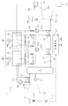
- FIG. 1 shows a schematic configuration diagram of a compressed air energy storage (CAES) power generator 2 according to a first embodiment of the present invention.
- the CAES power generator 2 equalizes output fluctuations to the power system 25 when generating power using renewable energy, and outputs power in accordance with power demand fluctuations in the power system 25.
- the CAES power generator 2 leveles the output fluctuations of the power generator 1 that uses renewable energy.
- the CAES power generator 2 includes a second power distribution unit 3, a motor (electric motor) 4, a compressor 6, a pressure accumulation tank 8, an expander 10, a generator 12, a pressure sensor 14, a first heat exchanger 16, and a second heat exchange.
- the input power generated by the power generation device 1 that uses renewable energy is supplied to the motor 4 via the second power distribution unit 3.
- the motor 4 is driven by this electric power.
- the motor 4 is mechanically connected to the compressor 6.
- the input power from the power generation device 1 can also be supplied to the heater 22 via the second power distribution unit 3.
- the input power is normally supplied to the motor 4, but the second power distribution unit 3 is switched according to the magnitude of the input power and supplied to the heater 22 as will be described later. Therefore, the 2nd electric power distribution part 3 of this embodiment is electrically connected to the electric power generating apparatus 1, the motor 4, and the heater 22 (refer the broken line of FIG. 1).
- the compressor 6 operates by driving the motor 4.
- the discharge port 6 b of the compressor 6 is fluidly connected to the pressure accumulation tank 8 via the first heat exchanger 16.
- the compressor 6 sucks air from the suction port 6 a, compresses it, discharges it from the discharge port 6 b, and pumps it to the pressure accumulation tank 8.
- the rotation speed of the motor 4 of the compressor 6 is controlled by an inverter (not shown), and the stability of the operation state can be confirmed by confirming the rotation speed via the inverter.
- the pressure accumulating tank 8 is provided with a pressure sensor 14 for detecting the pressure of the compressed air stored inside.
- the pressure accumulation tank 8 is fluidly connected to the expander 10 via the second heat exchanger 18.
- the pressure accumulation tank 8 stores the compressed air that has been pumped.
- the accumulator tank 8 has a small capacity with respect to a necessary power demand peak. Equipment cost can be reduced by reducing the capacity of the pressure accumulation tank 8. Further, by using the small-capacity pressure accumulation tank 8, it is possible to shorten the time taken to increase the pressure until the pressure is suitable for power generation. Therefore, it is easy to always maintain a high pressure. For this reason, the responsiveness to fluctuations in power demand can be improved. Thus, energy can be stored in the pressure accumulation tank 8 as compressed air.
- the compressed air stored in the pressure accumulating tank 8 is supplied to the expander 10.
- the fluid connection of the compressor 6, the first heat exchanger 16, the pressure accumulation tank 8, the second heat exchanger 18, and the expander 10 is made through an air supply path 28.
- a valve 29 is provided in the air supply path 28 from the pressure accumulation tank 8 to the expander 10, and the supply of compressed air to the expander 10 can be allowed or blocked.
- the expander 10 is mechanically connected to the generator 12.
- the expander 10 that is supplied with compressed air from the air supply port 10a is operated by the supplied compressed air and drives the generator 12.
- the expanded air is exhausted from the exhaust port 10b.
- the generator 12 is electrically connected to the first power distribution unit 24.
- the electric power generated by the generator 12 driven by the expander 10 is supplied to the first power distribution unit 24.
- the first power distribution unit 24 is electrically connected to the generator 12, the external power system 25, and the heater 22 (see the broken line in FIG. 1).
- the first power distribution unit 24 distributes the power supplied from the generator 12 to the external power system 25 and the heater 22. For example, in the distribution, half of the power supplied from the generator 12 may be supplied to the external power system 25 and the other half may be supplied to the heater 22. Further, all of the electric power supplied from the generator 12 can be supplied to the heater 22 or the electric power system 25.
- the input power generated by the power generation device 1 and the power demand from the external power system 25 can be measured as a supply and demand balance in the power network like a smart grid, and these measured values are output to the control device 26 described later.
- the input power may be estimated based on past weather data, and the power demand may be estimated based on past demand data.
- the input power may be estimated based on current weather data.
- the power generation device 1 is measured by measuring wind power at a location slightly above the wind of the power generation device 1, and in the case of solar power generation, by observing the movement of clouds in the vicinity of the power generation device 1.
- the input power to be generated may be estimated.
- the ratio of distribution by the first power distribution unit 24 is determined by the control device 26 described later based on these measured values and estimated values.
- compressor 6 and the expander 10 of this embodiment are screw types, the kind is not limited, A scroll type, a turbo type, a reciprocating type, etc. may be sufficient.
- the number of the compressors 6 and the expanders 10 is one, but the number is not particularly limited, and may be two or more.
- the heat storage tank 20 is insulated.
- the heat storage tank 20 is fluidly connected to the first heat exchanger 16 and the second heat exchanger 18 through the heat medium supply passages 30a and 30b, respectively (see the one-dot chain line in FIG. 1).
- a heating medium flows in the heating medium supply paths 30a and 30b.
- the type of the heat medium is not limited, and may be water, oil, or the like, for example.
- Pumps 32a and 32b are provided in the heat medium supply paths 30a and 30b, respectively.
- the pump 32a circulates the heat medium between the heat storage tank 20 and the first heat exchanger 16 via the heat medium supply path 30a.
- the pump 32b circulates the heat medium between the heat storage tank 20 and the first heat exchanger 16 via the heat medium supply path 30b.
- the heat storage tank 20 is provided with a heater 22 for heating the internal heat medium.
- the heater 22 is an electric heater, and is supplied with electric power from the generator 12 via the first electric power distribution unit 24 to heat the heat medium.
- the first heat exchanger 16 heat is exchanged between the compressed air in the air supply path 28 between the compressor 6 and the pressure accumulation tank 8 and the heat medium in the heat medium supply path 30 a, and compression by the compressor 6 is performed.
- the generated compression heat is recovered in the heat medium. That is, in the first heat exchanger 16, the temperature of the compressed air decreases and the temperature of the heat medium increases.
- the heat medium whose temperature has increased here is supplied to and stored in the heat storage tank 20.
- the second heat exchanger 18 heat is exchanged between the compressed air in the air supply path 28 between the accumulator tank 8 and the expander 10 and the heat medium in the heat medium supply path 30b, and the expansion of the expander 10 is performed.
- the temperature of the compressed air is raised before. That is, in the 2nd heat exchanger 18, the temperature of compressed air rises and the temperature of a heat carrier falls.
- the heat medium whose temperature has been reduced is supplied to and stored in the heat storage tank 20.
- the first heat exchanger 16 and the second heat exchanger 18 When the first heat exchanger 16 and the second heat exchanger 18 are used, it is possible to prevent a decrease in power generation efficiency. When these are not used, compressed air whose temperature has been increased by the compression heat is supplied to the pressure accumulation tank 8. The compressed air whose temperature has risen is radiated to the outside while being stored in the pressure accumulating tank 8 and loses heat energy. On the other hand, if the 1st heat exchanger 16 is used, the temperature of the compressed air supplied to the pressure accumulation tank 8 can be reduced, and the temperature difference with external air can be reduced. Therefore, loss of thermal energy due to heat radiation in the pressure accumulation tank 8 can be prevented. Furthermore, the recovered heat is stored in the heat storage tank 20, and the generated heat is reduced by returning the recovered and stored heat to the compressed air supplied to the expander 10 using the second heat exchanger 18. Power generation is possible without any problems.
- surplus power is used for heat storage, power waste is suppressed, power generation efficiency is improved, and equipment cost can be reduced by reducing the size of the pressure storage tank 8.
- the surplus power means the power difference between the power generated by the generator 12 and the power demand. Normally, surplus power when the pressure accumulation tank 8 cannot accumulate any more pressure is discarded. However, the heating medium in the heat storage tank 20 is heated by the heater 22 so that the heated heating medium heats the compressed air before expansion in the second heat exchanger 18, so the expander 10 is heated with the compressed air thus heated. And the expansion efficiency can be improved. Further, the capacity of the pressure accumulating tank 8 of the entire apparatus 2 needs to be set corresponding to the peak of power demand.
- the CAES power generation device 2 includes a control device 26.
- the control device 26 is constructed by hardware including a sequencer and the software installed therein.
- the control device 26 receives values of input power from the power generation device 1, pressure values detected by the pressure sensor 14, power demand of the external power system 25, and power generation power of the generator 12. Then, the control device 26 controls the first power distribution unit 24 and the second power distribution unit 3 based on these values so that the supply destination of the generated power and the supply destination of the input power are indicated in the following control method. Switching (refer to the two-dot chain line in FIG. 1).
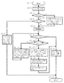
- FIG. 2 is a flowchart showing a control method of the CAES power generator 2 of the first embodiment.
- Control is started (step S2-1), when the input power E is supplied to the motor 4 (step S2-2), the input power E is equal to or less than a predetermined value E max (step S2 -3).
- the predetermined value E max is a maximum value at which the compressor 6 can be driven at a predetermined compression efficiency or higher. Therefore, when power exceeding E max is supplied, compression is performed at a point away from the set point that maximizes compression efficiency, and the compression efficiency decreases. Alternatively, a larger amount of power becomes a surplus power supply for driving the motor 4.
- step S2-3) When the input power E exceeds the predetermined value E max (step S2-3), the power of the portion of the input power E exceeding E max is supplied to the second heater 22 to heat the heat medium in the heat storage tank 20. (Step S2-4). Then, process A shown in FIG. 3 is executed (step S2-5).
- step S3-1 when process A is started (step S3-1), motor 4 is driven by input power to produce compressed air by compressor 6 (step S3-2).
- the compression heat is recovered into a heat medium by the first heat exchanger 16 (step S3-3), and the recovered heat medium is stored in the heat storage tank 20.
- the compressed air whose temperature has been recovered by heat recovery is stored in the pressure accumulation tank 8 (step S3-4).
- the compressed air supplied from the pressure accumulation tank 8 to the expander 10 is heated by the heat medium in the second heat exchanger 18 (step S3-5). Electric power is generated by the generator 12 by expanding the compressed air with the expander 10 (step S3-6). Then, the process A ends (step S3-7).
- the predetermined value E min is a minimum value at which the compressor 6 can be driven at a predetermined compression efficiency or higher. Therefore, even if power less than E min is supplied, compression is performed at a point away from the set point that maximizes the compression efficiency, and the compression efficiency decreases. Alternatively, even smaller electric power cannot be used to drive the motor 4 and is wasted even if electric power is supplied.
- FIG. 4 is a graph showing a range in which the compressor 6 can be operated with a suction efficiency of a certain level or higher.
- the horizontal axis represents the rotational speed (rotational speed) R of the compressor 6, and the vertical axis represents the suction efficiency of the compressor.
- the rotational speed R in a predetermined range R min ⁇ R ⁇ R max
- E min ⁇ E ⁇ E max E min ⁇ E ⁇ E max
- step S2-3 and step S2-6 it is confirmed whether or not it is within a predetermined range (E min ⁇ E ⁇ E max ), and it is determined whether or not it is possible to operate with a certain efficiency or more. .
- the input power E is less than the predetermined value E min (step S2-6)
- the input power E is supplied to the heater 22 to heat the heat medium in the heat storage tank 20 (step S2-7).
- the predetermined value E min step S2-6)
- the process A shown in FIG. 3 is executed (step S2-5).
- the operation efficiency may be determined by checking the rotational speed via an inverter (not shown) connected to the compressor 6 as described above.
- step S2-5) it is determined whether or not the power demand Wd is equal to or greater than the generated power Wg (step S2-8).
- the power demand Wd is equal to or greater than the generated power Wg, there is no surplus power, and therefore all the generated power Wg (maximum Wd) is supplied to the external power system 25 that is the demand destination (step S2-9).
- the power demand Wd is not equal to or greater than the generated power Wg, it is determined whether the capacity of the pressure accumulating tank 8 is equal to or greater than a predetermined value (step S2-10). Specifically, it is determined whether or not the internal pressure of the pressure accumulation tank 8 detected by the pressure sensor 14 is equal to or higher than a predetermined pressure.
- the predetermined pressure is set to a pressure value at which compressed air cannot be pumped any more from the compressor 6 to the accumulator tank 8.
- step S2-11 When the capacity of the pressure accumulating tank 8 is not equal to or higher than a predetermined pressure, a part (maximum Wd) of the generated power Wg is supplied to the external power system 25 and surplus power (Wg ⁇ Wd) is supplied to the motor 4 of the compressor 6. Compressed air is manufactured and stored (step S2-11). When the capacity of the pressure accumulating tank 8 is greater than or equal to a predetermined value, a part of the generated power Wg (maximum Wd) is supplied to the external power system 25 and the surplus power (Wg ⁇ Wd) cannot be stored any more, and is supplied to the heater 22. The heat medium in the heat storage tank 20 is heated (step S2-12).
- step S2-13 The compressed air before expansion is heated with the heat medium heated in the second heat exchanger 18 (step S2-13), and the compressed air is expanded in the expander 10 to generate power by the generator 12 (step S2-14).
- the generated power Wg is supplied to the external power system 25 that is the demand destination (step S2-9). After completing these processes, the control is terminated (step S2-15).
- control is terminated here, the control is always performed during the operation, and when the input power E is supplied to the motor 4 again, the process is started again from step S2-1.
- the input power E that is too small or too large so that the efficiency of the compressor 6 is less than a certain level is usually not available and discarded, but in this configuration, the input power E that is too small or too large is also stored. Available to:
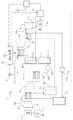
- FIG. 5 shows a CAES power generator 2 according to the second embodiment.
- the CAES power generation device 2 of the present embodiment has a configuration other than the portions related to the second power distribution unit 3 (see FIG. 1), the first heat storage tank 34, the second heat storage tank 36, and the third heat exchanger 38. 1 is substantially the same as the first embodiment. Therefore, the same parts as those shown in FIG.
- the second power distribution unit 3 (see FIG. 1) is omitted, and a first heat storage tank 34 and a second heat storage tank 36 are provided. Both the first heat storage tank 34 and the second heat storage tank 36 are insulated.
- the first heat storage tank 34 and the second heat storage tank 36 are provided with a first temperature sensor 40a and a second temperature sensor 40b for detecting the temperatures of the first heat medium and the second heat medium, respectively.
- the types of the first heat medium and the second heat medium may be the same or different. For example, water or oil may be used.
- a heater 22 is disposed in the second heat storage tank 36. The heater 22 is electrically connected to the generator 12.
- the first heat exchanger 16 is fluidly connected to the compressor 6 and the pressure accumulation tank 8 through the air supply path 28. Further, it is fluidly connected to the first heat storage tank 34 through the heat medium supply path 30c.
- a pump 32c for flowing and circulating the first heat medium inside is disposed in the heat medium supply path 30c. Due to the heat exchange in the first heat exchanger 16, the temperature of the compressed air decreases and the temperature of the first heat medium increases.
- the second heat exchanger 18 is fluidly connected to the pressure accumulation tank 8 and the third heat exchanger 38 through the air supply path 28. Further, it is fluidly connected to the first heat storage tank 34 and the second heat storage tank 36 through the heat medium supply path 30d.
- a pump 32d for flowing and circulating the first heat medium or the second heat medium inside is disposed in the heat medium supply path 30d.
- the third heat exchanger 38 is fluidly connected to the second heat exchanger 18 and the expander 10 through the air supply path 28. Further, it is fluidly connected to the first heat storage tank 34 and the second heat storage tank 36 through the heat medium supply path 30e.
- a pump 32e for flowing and circulating the first heat medium or the second heat medium is disposed in the heat medium supply path 30e. Due to the heat exchange in the third heat exchanger 38, the temperature of the compressed air rises and the temperature of the first heat medium or the second heat medium falls.
- the first heat storage tank 34 and the second heat storage tank 36 are connected to the first heat exchanger 16 and the second heat exchanger 18 through switching valves (heat exchange order switching units) 42a to 42d, 44a to 44d, 46. It has been done. Therefore, the heat medium in the first heat storage tank 34 can be supplied to both the first heat exchanger 16 and the second heat exchanger 18, and is separated from the heat medium in the second heat storage tank 36. Similarly, the heat medium in the second heat storage tank 36 can be supplied to both the second heat exchanger 18 and the third heat exchanger 38, and is separated from the heat medium in the first heat storage tank 34. The first heat medium and the second heat medium share the heat medium supply paths 30d and 30e, but do not flow through the same heat medium supply path 30d or 30e at the same time.
- the power generation efficiency can be further improved.
- the temperature of the heat medium usually differs. Therefore, heat storage at different temperatures is possible by separating the two heating media. For this reason, power generation efficiency can be improved more.
- the control device 26 of the present embodiment includes input power from the power generation device 1, detection pressure value of the pressure sensor 14, detection temperature value of the temperature sensors 40 a and 40 b, power demand of the external power system 25, and power generation of the generator 12.
- the first power distribution unit 24 is controlled to switch the supply destination of the generated power (see the two-dot chain line in FIG. 5), and the switching is performed.
- the heating medium flow path is switched by controlling the valves 42a to 42d, 44a to 44d, and 46.
- FIG. 6 is a flowchart showing a control method of the CAES power generator 2 of the second embodiment.
- Steps S6-1 to S6-8 in this embodiment are substantially the same as steps S2-1 to S2-12 in the first embodiment shown in FIG. Therefore, the description of the same steps is omitted.
- the process of determining the magnitude of the input power E (steps S2-3, S2-4, S2-6, S2-7) is omitted, and step S6- In step 3, process B is executed instead of process A.
- the difference between them is that the heating medium in steps S3-3 and S3-5 is replaced with the first heating medium in S7-3 and S7-5. It is that. This is because, in contrast to the single heat medium in the first embodiment, two heat mediums, the first and second heat mediums, are used in the present embodiment.
- the first and second heating media are not limited to different types, and the same heating media may be used.
- step S6-9 whether or not the first heating medium temperature detected by temperature sensor 40a is higher than the second heating medium temperature detected by temperature sensor 40b after heating the second heating medium in step S6-8. Is determined (step S6-9).
- the switching valves 42a to 42d and 46 are opened, and the switching valves 44a to 44d are closed.
- the first heat medium exchanges heat with the compressed air in the third heat exchanger 38 (step S6). -11).
- the switching valves 42a to 42d are closed and the switching valves 44a to 44d and 46 are opened.
- the second heat medium exchanges heat with the compressed air in the third heat exchanger 38 (step S6). -13). That is, of the first heat medium and the second heat medium, the heat medium having a lower temperature first exchanges heat with the compressed air.
- the expander 10 is driven by the heated compressed air, and power is generated by the generator 12 (step S6-14).
- the generated power Wg is supplied to the external power system 25 (step S6-5). After completing these processes, the control is terminated (step S6-15).
- FIG. 8 shows a CAES power generator 2 according to the third embodiment.
- the CAES power generation device 2 of the present embodiment includes a second power distribution unit 3 (see FIG. 1), a first heat medium supply tank 48, a second heat medium supply tank 50, a first heat medium return tank 52, and a second heat medium.
- the parts related to the return tank 54, the fourth heat exchanger 56, and the fifth heat exchanger 58, and the configuration other than that the compressor 6 and the expander 10 are multistage types are the same as in the first embodiment of FIG. It is. Therefore, the same parts as those shown in FIG.
- the second power distribution unit 3 is omitted, and heat storage tanks 48, 50, 52, and 54 that are insulated are provided for each temperature.
- a first heat medium supply tank 48, a second heat medium supply tank 50, a first heat medium return tank 52, and a second heat medium return tank 54 are provided.
- the 1st heat exchanger 16, the 2nd heat exchanger 18, the 4th heat exchanger 56, and the 5th heat exchanger 58 corresponding to these are provided, respectively.
- the first heat medium supply tank 48 and the first heat medium return tank 52 are fluidly connected to the first heat exchanger 16 and the second heat exchanger 18 through the heat medium supply path 30f.
- a pump 32f that causes the internal heat medium to flow and circulate is disposed in the heat medium supply path 30f.
- the first heat medium supply tank 48 stores the heat medium whose temperature has increased due to heat exchange with compressed air in the first heat exchanger 16.
- the first heat medium return tank 52 stores the heat medium whose temperature has decreased due to heat exchange with the compressed air in the second heat exchanger 18.
- the second heat medium supply tank 50 and the second heat medium return tank 54 are fluidly connected to the fourth heat exchanger 56 and the fifth heat exchanger 58 through the heat medium supply path 30g.
- a pump 32g for flowing and circulating the internal heat medium is disposed in the heat medium supply path 30g.
- the second heat medium supply tank 50 stores the heat medium whose temperature has increased through heat exchange with the compressed air in the fourth heat exchanger 56.
- the second heat medium return tank 54 stores the heat medium whose temperature has decreased due to heat exchange with the compressed air in the fifth heat exchanger 58.
- the compressor 6 and the expander 10 of this embodiment are a two-stage type.
- the first stage compression heat is recovered by the fourth heat exchanger 56, and the second stage compression heat is recovered by the first heat exchanger 16.
- the compressed air before expansion is heated by the second heat exchanger 18 and the compressed air is heated by the fifth heat exchanger 58 after the first stage expansion.
- the heat medium can be managed according to the temperature. Therefore, heat exchange efficiency can be improved and power generation efficiency can be improved.
- the two-stage compressor 6 and the expander 10 are arranged, but the present invention is not limited to this, and a single-stage type or a multi-stage type having three or more stages may be used.
- the control device 26 of the present embodiment receives the input power from the power generation device 1, the detected pressure value of the pressure sensor 14, the power demand of the external power system 25, and the output of the power generation power of the generator 12. Based on this, the first power distribution unit 24 is controlled to switch the supply destination of the generated power (see the two-dot chain line in FIG. 11).
- control method according to the present embodiment is substantially the same as the control method according to the first embodiment shown in FIG. 2 except for the portion related to the second power distribution unit 3 (see FIG. 1), and thus the description thereof is omitted.
- FIG. 9 shows a CAES power generator 2 according to the fourth embodiment.
- the CAES power generator 2 of the present embodiment is the same as the first embodiment of FIG. 1 except for the portions related to the heater 22 (see FIG. 1) and the power storage device 21. Therefore, the same parts as those shown in FIG.
- the CAES power generation device 2 of the present embodiment is provided with a power storage device 21 without the heater 22 (FIG. 1).
- the power storage device 21 is not particularly limited as long as it can store electrical energy such as a storage battery or a capacitor.
- the power storage device 21 is electrically connected to the generator 12 via the first power distribution unit 24 and stores surplus power generated by the generator 12. The remaining power stored in the power storage device 21 can be grasped by a power meter (not shown).
- the power storage device 21 is electrically connected to the power generation device 1 via the second power distribution unit 3 and stores the input power generated by the power generation device 1.
- the power storage device 21 is electrically connected to the motor 4 and can supply the stored power. Moreover, it is electrically connected also to the electric power generating apparatus 1 via the 2nd electric power distribution part 3, and can store input electric power.
- the power storage device 21 is electrically connected to the power system 25 and can supply the stored power.
- the first power distribution unit 24 of the present embodiment distributes the power from the generator 12 to the power system 25 and the power storage device 21.
- the second power distribution unit 3 distributes the electric power from the power generation device 1 to the motor 4 and the power storage device 21.
- the control device 26 of the present embodiment includes each of the input power from the power generation device 1, the detected pressure value of the pressure sensor 14, the power demand of the external power system 25, the generated power of the generator 12, and the remaining power of the power storage device 21. Receive value. Then, the control device 26 controls the first power distribution unit 24 and the second power distribution unit 3 based on these values so that the supply destination of the generated power and the supply destination of the input power are indicated in the following control method. Switching (see the two-dot chain line in FIG. 9).
- FIG. 10 is a flowchart showing a control method of the CAES power generator 2 of the fourth embodiment. Since the control method of the present embodiment is substantially the same as the control method of the first embodiment shown in FIG. 2, only the differences are shown.
- step S10-4 more power than is necessary to drive the compressor 6 is supplied to the power storage device 21 (step S10-4).
- step S10-7 For input power E that is too small such that the operating efficiency of the compressor 6 is less than or equal to a predetermined value, when the power storage device 21 has power (step S10-7), the input power E is equal to or greater than a predetermined value Emin.
- step S10-8 After supplementary power is supplied from the power storage device 21 to the motor 4 (step S10-8), the process A is executed (step S10-9).
- step S10-10 the input power E is supplied to the power storage device 21 and stored (step S10-10).
- the input power E that is too small and the input power E that is too large so that the operation efficiency of the compressor 6 is equal to or less than the predetermined value can be effectively used by storing the power. Further, even if the input power E supplied to the motor 4 is below a predetermined value E min, supplied from the power storage device 21 to the motor 4 is a predetermined value E min or more power by auxiliary power the motor 4 As a result, a decrease in operating efficiency can be prevented.
- step S10-15 when the internal pressure of pressure storage tank 8 is equal to or higher than a predetermined pressure (step S10-13), it is determined whether power storage device 21 is fully charged (step S10-15). When the power storage device 21 is not fully charged, a part (maximum Wd) of the generated power Wg is supplied to the external power system 25, and surplus power (Wg ⁇ Wd) is supplied to the power storage device 21 and stored (step S10 ⁇ ). 16). When the power storage device 21 is fully charged, a part (maximum Wd) of the generated power Wg is supplied to the external power system 25 and cannot be charged any more, so surplus power (Wg ⁇ Wd) is discharged (discarded) (Ste S10-17).
- FIG. 11 shows a CAES power generator 2 according to the fifth embodiment.
- the CAES power generation device 2 of the present embodiment includes both the power storage device 21 and the heater 22. Configurations other than those related to the power storage device 21 and the heater 22 are the same as those in the first embodiment in FIG. 1 and the fourth embodiment in FIG. 9. Therefore, the same components as those shown in FIGS. 1 and 9 are denoted by the same reference numerals and description thereof is omitted.
- the CAES power generation device 2 of the present embodiment includes both the power storage device 21 and the heater 22. Therefore, the first power distribution unit 24 of the present embodiment distributes the power from the generator 12 to the power system 25, the power storage device 21, and the heater 22. The second power distribution unit 3 distributes input power from the power generation device 1 to the motor 4, the power storage device 21, and the heater 22.
- the heat storage tank 20 is provided with a heat storage temperature sensor 60 for measuring the temperature of the internal heat medium.
- the temperature sensor 60 outputs a measured value to the control device 26.
- the control device 26 of the present embodiment includes input power from the power generation device 1, detected pressure value of the pressure sensor 14, detected temperature value of the temperature sensor 60, power demand of the external power system 25, generated power of the generator 12, and storage power. Each value of the remaining power of the device 21 is received. And based on these values, the 1st electric power distribution part 24 and the 2nd electric power distribution part 3 are controlled, and the supply destination of generated electric power is switched (refer the dashed-two dotted line of FIG. 11). There are a first control method and a second control method described below as control methods for switching the supply destination of generated power.
- FIG. 12 is a flowchart showing a first control method of the CAES power generator 2 of the fifth embodiment. Since the first control method of the present embodiment is substantially the same as the control method of the first embodiment shown in FIG. 2, only the differences are shown.
- step S12-7 When the input power E is smaller than the predetermined value E min (step S12-6) and the power storage device 21 has power (step S12-7), the power storage device so that the input power E becomes equal to or greater than the predetermined value E min. After auxiliary power is supplied from 21 to the motor 4 (step S12-8), process A is executed (step S12-9). When there is no power in the power storage device 21 (step S12-7), the first power distribution unit 24 is switched to supply the input power E to the heater 22 to heat the heat medium in the heat storage tank 20 (step S12-10). .
- step S12-15 When the heat medium in the heat storage tank 20 is equal to or higher than the predetermined temperature (step S12-15), a part (maximum Wd) of the generated power Wg is supplied to the external power system 25, and the surplus power (Wg-Wd) is stored. The power is supplied to the device 21 and stored (step S12-16).
- step S12-15 When the heat medium in the heat storage tank 20 is lower than the predetermined temperature (step S12-15), a part (maximum Wd) of the generated power Wg is supplied to the external power system 25, and the surplus power (Wg-Wd) is heated. 22 is heated to heat the heat medium in the heat storage tank 20 (step S12-16).
- surplus power can be stored by providing the power storage device 21 in addition to the heater 22.
- energy can be stored effectively as electric energy.
- fluctuations in the amount of power generated by renewable energy difference between peak time and normal time
- a large-sized pressure storage tank 8 or a large number of pressure storage tanks 8 are required unless a device for effectively using surplus power is used. . Since the cost of the pressure accumulation tank 8 occupying the total cost is large, even if the power storage device 21 is newly installed, the overall cost can be greatly reduced by reducing the capacity of the pressure accumulation tank 8.
- FIG. 13 is a flowchart showing a second control method of the CAES power generator 2 of the fifth embodiment. Since the second control method of the present embodiment is substantially the same as the first control method shown in FIG. 12, only different points are shown.
- step S13-10 the input power E is supplied to the power storage device 21. Since the power storage device 21 stores energy as electrical energy, it has a wider range of applications than when the heater 22 is used to store energy as thermal energy as in the first control method. Further, it is determined whether or not the power storage device 21 is fully charged (step S13-15). If it is not fully charged, surplus power is supplied to the power storage device 21 with higher priority than the heater 22 to store power (step S13). -15). When the battery is fully charged, no more power can be stored, so surplus power is supplied to the heater 22 to heat the heat medium in the heat storage tank 20 (step S13-17).
- the input power and surplus power are supplied to the power storage device 21 and the heater 22 as necessary, and are stored as electric energy or heat energy.
- input power and surplus power may be stored in other modes.
- the target of power generation by renewable energy is steady (or repetitive) with natural forces such as wind, sunlight, solar heat, wave or tidal power, running water or tide, and geothermal heat. It is possible to target anything that uses energy replenished.
Landscapes
- Engineering & Computer Science (AREA)
- General Engineering & Computer Science (AREA)
- Mechanical Engineering (AREA)
- Physics & Mathematics (AREA)
- Combustion & Propulsion (AREA)
- Chemical & Material Sciences (AREA)
- Thermal Sciences (AREA)
- Life Sciences & Earth Sciences (AREA)
- High Energy & Nuclear Physics (AREA)
- Sustainable Development (AREA)
- Sustainable Energy (AREA)
- Power Engineering (AREA)
- Engine Equipment That Uses Special Cycles (AREA)
Abstract
圧縮空気貯蔵発電装置2は、第1熱交換器16、蓄熱タンク20、第2熱交換器18、加熱部22、第1電力分配部24、及び制御装置26を備える。第1熱交換器16は、圧縮機6からの圧縮空気と熱媒とで熱交換する。蓄熱タンク20は、第1熱交換器16で熱交換された熱媒を蓄える。第2熱交換器18は、蓄圧タンク8からの圧縮空気と蓄熱タンク20からの熱媒とで熱交換する。加熱部22は、発電機12の電力で熱媒を加熱する。第1電力分配部24は、発電機12の発電電力を電力系統25と加熱部22とに分配する。制御装置26は、蓄圧タンク8の内圧が所定の圧力に達し、電力需要よりも発電電力が多い場合、第1電力分配部24により発電電力の一部又は全部を加熱部22に供給する制御を行う。そのため、圧縮空気貯蔵発電装置2の発電効率を向上し、設備コストを低減可能である。
Description
本発明は、圧縮空気貯蔵発電装置及び圧縮空気貯蔵発電方法に関する。
風力発電や太陽光発電などの再生可能エネルギーを利用した発電は、気象条件に依存するため、出力が安定しないことがある。このため、CAES(compressed air energy storage)システム等のエネルギー貯蔵システムを使用して出力を平準化する必要がある。
従来の圧縮空気貯蔵(CAES:compressed air energy storage)発電装置は、電力プラントのオフピーク時間中に電気エネルギーを圧縮空気として蓄圧タンクに蓄え、高電力需要時間中に圧縮空気により膨張機を駆動して発電機を作動させて電気エネルギーを生成するのが一般的である。
また、発電効率を向上させるために、圧縮空気の圧縮熱を熱回収して蓄熱タンク等に貯蔵し、膨張前の圧縮空気に熱を戻すことで、蓄圧タンクで放熱することによる熱エネルギー損失を防止するものがある。
このようなCAES発電装置として、例えば特許文献1には、熱エネルギー貯蔵システムを利用したCAES発電装置が開示されている。
しかし、圧縮空気を蓄える蓄圧タンクは、高電力需要のピーク時の容量に対応するサイズで製造すると大型の蓄圧タンクが必要である。従って、多くの設備コストがかかる。
本発明は、発電効率を向上し、設備コストを低減できる圧縮空気貯蔵発電装置を提供することを課題とする。
本発明の第1の態様は、再生可能エネルギーを用いて発電した入力電力により駆動される電動機と、前記電動機と機械的に接続され、空気を圧縮する圧縮機と、前記圧縮機と流体的に接続され、前記圧縮機により圧縮された圧縮空気を蓄える蓄圧タンクと、前記蓄圧タンクの内圧を検出する圧力センサと、前記蓄圧タンクと流体的に接続され、前記圧縮空気によって駆動される膨張機と、前記膨張機と機械的に接続され、電力を発電する発電機と、前記圧縮機と流体的に接続され、前記圧縮機から供給される前記圧縮空気と熱媒とで熱交換する第1熱交換器と、前記第1熱交換器と流体的に接続され、前記第1熱交換器で熱交換された前記熱媒を蓄える蓄熱タンクと、前記蓄圧タンク及び前記蓄熱タンクと流体的に接続され、前記蓄圧タンクから供給された前記圧縮空気と前記蓄熱タンクから供給された前記熱媒とで熱交換する第2熱交換器と、前記発電機で発電した電力を使用して前記蓄熱タンク内の前記熱媒を加熱する加熱部と、前記発電機の発電電力を少なくとも電力系統と前記加熱部とに分配する第1電力分配部と、前記蓄圧タンクの内圧が所定の値に達し、前記電力系統における電力需要よりも前記発電機の発電電力が多い場合、前記第1電力分配部を制御して前記発電機の発電電力の一部又は全部を前記加熱部に供給する制御装置とを備える、圧縮空気貯蔵発電装置を提供する。
この構成によれば、余剰電力を蓄熱に利用することで電力の無駄を抑制して発電効率を向上し、蓄圧タンクのサイズを小容量化することで設備コストを低減できる。余剰電力とは、発電機による発電電力と電力需要との差分の電力のことをいう。通常、蓄圧タンクがそれ以上蓄圧できない場合の余剰電力は捨てることになる。しかし、加熱部により蓄熱タンク内の熱媒を加熱することで、加熱された熱媒は第2熱交換器において膨張前の圧縮空気を加熱するため、加熱された圧縮空気で膨張機を駆動でき、膨張効率を向上できる。また、装置全体の蓄圧タンクの容量(蓄圧タンクが複数ある場合はそれらの容量の合計)は、電力需要のピークに対応して設定する必要がある。しかし、本構成により余剰電力を蓄熱に利用できるため電力の無駄を抑制でき、蓄圧タンクが所定の容量を超過してそれ以上蓄圧できない場合でも熱という別の形態でエネルギーを貯蔵できる。このため、蓄圧タンクの容量を電力需要のピークに対応して設定する必要がなく、蓄圧タンクを小容量化できる。
前記圧縮空気貯蔵発電装置は、前記入力電力を前記電動機と前記加熱部とに分配する第2電力分配部をさらに備え、前記圧縮機の運転効率が所定以下となる場合、前記制御装置は前記第2電力分配部を制御して前記入力電力を前記加熱部に供給することが好ましい。
圧縮機の運転効率が所定以下となる場合でも、入力電力を蓄熱に利用できることで、入力電力を効率的に利用できる。運転効率が所定以下となる場合とは、入力電力が所定の値より小さな場合又は所定の値より大きな場合に起こる。運転効率が所定以下となるような圧縮機を駆動するのに小さすぎる入力電力や圧縮機を駆動するのに大きすぎる入力電力は、は通常利用できず捨てられることになる。しかし、本構成ではこのような小さな入力電力や大きな入力電力も加熱部に供給することで蓄熱に利用できる。
前記圧縮空気貯蔵発電装置は、前記発電機に電気的に接続され、前記発電機の発電電力を蓄える蓄電装置と、前記蓄熱タンク内の熱媒の温度を検出する温度センサをさらに備え、前記第1電力分配部は、前記発電機の電力を、前記電力系統と前記加熱部と前記蓄電装置とに分配し、前記制御装置は、前記蓄圧タンクの内圧が所定の圧力に達し、前記電力系統における電力需要よりも前記発電機で発電する電力が多く、さらに前記温度センサで測定した前記蓄熱タンク内の熱媒の温度が所定の温度以上である場合、前記第1電力分配部を制御して前記発電機で発電した電力の一部又は全部を前記蓄電装置に供給することが好ましい。
加熱部に加えて、蓄電装置を設けたことで余剰電力を蓄電できる。特に、蓄熱タンク内の熱媒温度が所定以上であり、加熱部によって熱媒温度を上昇させることができない場合でも電気エネルギーとして有効にエネルギーを蓄えることができる。特に、再生可能エネルギーによる発電量の変動(ピーク時と平常時の差)が大きい場合、余剰電力を有効利用する工夫がなされていないと膨大なサイズの蓄圧タンク又は多数の蓄圧タンクが必要となる。全体コストに占める蓄圧タンクのコストは大きいため、例え蓄電装置を新たに設置した場合でも蓄圧タンクの小容量化により全体として大きくコストダウンできる。
また、本発明は、再生可能エネルギーを用いて発電した入力電力により駆動される電動機と、前記電動機と機械的に接続され、空気を圧縮する圧縮機と、前記圧縮機と流体的に接続され、前記圧縮機により圧縮された圧縮空気を蓄える蓄圧タンクと、前記蓄圧タンクの内圧を検出する圧力センサと、前記蓄圧タンクと流体的に接続され、前記圧縮空気によって駆動される膨張機と、前記膨張機と機械的に接続され、電力を発電する発電機と、前記圧縮機と流体的に接続され、前記圧縮機から供給される前記圧縮空気と熱媒とで熱交換する第1熱交換器と、前記第1熱交換器と流体的に接続され、前記第1熱交換器で熱交換された前記熱媒を蓄える蓄熱タンクと、前記蓄圧タンク及び前記蓄熱タンクと流体的に接続され、前記蓄圧タンクから供給された前記圧縮空気と前記蓄熱タンクから供給された前記熱媒とで熱交換する第2熱交換器と、前記発電機に電気的に接続され、前記発電機の発電電力を蓄える蓄電装置と、前記発電機の発電電力を少なくとも電力系統と前記蓄電装置とに分配する第1電力分配部と、前記蓄圧タンクの内圧が所定の圧力に達し、前記電力系統における電力需要よりも前記発電機の発電電力が多い場合、前記第1電力分配部を制御して前記発電機の発電電力の一部又は全部を前記蓄電装置に供給する制御装置とを備える、圧縮空気貯蔵発電装置を提供する。
この構成によれば、余剰電力を蓄電に利用することで電力の無駄を抑制して発電効率を向上し、蓄圧タンクのサイズを小容量化することで設備コストを低減できる。
前記圧縮空気貯蔵発電装置は、前記入力電力を前記電動機と前記蓄電装置とに分配する第2電力分配部をさらに備え、前記圧縮機の運転効率が所定以下となる場合、前記制御装置は前記第2電力分配部を制御して前記入力電力を前記蓄電装置に供給することが好ましい。
圧縮機の運転効率が所定以下となるような小さすぎる入力電力や大きすぎる入力電力も蓄電することで有効に利用できる。
前記制御装置は、前記電動機に供給される入力電力が所定以下である場合、前記蓄電装置から前記電動機に電力を供給することが好ましい。
電動機に供給される入力電力が所定以下である場合でも、蓄電装置から電動機に電力を補助供給することで所定以上の電力が電動機に供給されることになり、運転効率の低下を防止できる。
前記圧縮空気貯蔵発電装置は、前記発電機で発電した電力を使用して前記蓄熱タンク内の前記熱媒を加熱する加熱部をさらに備え、前記第1電力分配部は、前記発電機の電力を、前記電力系統と前記蓄電装置と前記加熱部とに分配し、前記制御装置は、前記蓄圧タンクの内圧が所定の圧力に達し、前記電力系統における電力需要よりも前記発電機で発電する電力が多く、さらに前記蓄電装置が既に満充電の場合、前記第1電力分配部を制御して前記発電機で発電した電力の一部又は全部を前記加熱部に供給することが好ましい。
蓄電装置に加えて加熱部を設けたことで、余剰電力を蓄熱に利用できる。特に、蓄電装置が満充電であり、それ以上蓄電できない場合でも熱エネルギーとして有効にエネルギーを蓄えることができる。
前記熱媒は、分離された第1熱媒及び第2熱媒を含み、前記蓄熱タンクは、前記第1熱媒を蓄える第1蓄熱タンク及び前記第2熱媒を蓄える第2蓄熱タンクを備え、前記第1蓄熱タンクは、前記第1熱交換器及び前記第2熱交換器と流体的に接続され、前記第2蓄熱タンクは、蓄えている前記第2熱媒を前記加熱部により加熱され、前記蓄圧タンク及び前記第2蓄熱タンクと流体的に接続されて前記蓄圧タンクから供給される前記圧縮空気と前記第2蓄熱タンクから供給される前記第2熱媒とで熱交換する第3熱交換器をさらに備えることが好ましい。
この構成によれば、圧縮熱を回収する第1熱媒と加熱部により加熱される第2熱媒とを分離できるため、発電効率をより向上できる。圧縮熱又は加熱部による加熱では、加熱温度が異なる。従って、2つの熱媒を分離することで異なる温度での蓄熱が可能である。このため、発電効率をより向上できる。
前記圧縮空気貯蔵発電装置は、前記第1蓄熱タンクの温度を検出する第1温度センサと、前記第2蓄熱タンクの温度を検出する第2温度センサと、前記蓄圧タンクから供給される前記圧縮空気に対して、前記第2熱交換器又は前記第3熱交換器のいずれが先に作用するかを切り替える熱交換順序切替部とをさらに備え、前記制御装置は、前記第1温度センサの検出温度よりも前記第2温度センサの検出温度が高い場合には前記第2熱交換器を先に作用し、前記第2温度センサの検出温度よりも前記第1温度センサの検出温度が高い場合には前記第1熱交換器を先に作用するように前記熱交換順序切替部を制御することが好ましい。
この構成によれば、膨張前の圧縮空気の温度をより高温に加熱できるため、発電効率を向上できる。膨張前の圧縮空気に対し、熱交換の順番として第1熱媒と第2熱媒のうちの温度の高い方の熱媒を後に熱交換させる。従って、温度の高い方の熱媒が加熱した圧縮空気の温度を低下させることがない。このため、発電効率をより向上できる。
前記蓄圧タンクは、前記電力需要のピークに必要な容量よりも小容量であることが好ましい。
この構成によれば、蓄圧タンクを小容量化することで設備コストを低減できる。即ち、蓄圧タンクのサイズや数を電力需要のピークに合わせて大容量・多数の蓄圧タンクを用意する必要がない。また、小容量のタンクを使用することで発電に適した圧力になるまで昇圧するのにかかる時間を短縮できる。従って、常に高めの圧力に維持しておくことが容易である。このため、電力需要の変動への応答性を向上できる。
本発明の第2の態様は、再生可能エネルギーを用いて発電した入力電力により空気を圧縮し、圧縮した空気を貯蔵し、貯蔵した圧縮空気を膨張させることにより発電し、前記圧縮の工程で発生する圧縮熱を回収し、回収した圧縮熱を蓄熱し、前記膨張の工程前に膨張させる圧縮空気を蓄熱した圧縮熱により加熱し、前記貯蔵した圧縮空気の圧力が所定の値に達し、電力需要よりも発電電力が多い場合、前記発電電力の一部又は全部により前記蓄熱の温度をさらに上昇させる、圧縮空気貯蔵発電方法を提供する。
また、本発明は、再生可能エネルギーを用いて発電した入力電力により空気を圧縮し、圧縮した空気を貯蔵し、貯蔵した圧縮空気を膨張させることにより発電し、前記圧縮の工程で発生する圧縮熱を回収し、回収した圧縮熱を蓄熱し、前記膨張の工程前に膨張させる圧縮空気を蓄熱した圧縮熱により加熱し、前記貯蔵した圧縮空気の圧力が所定の値に達し、電力需要よりも発電電力が多い場合、前記発電電力の一部又は全部を蓄電する、圧縮空気貯蔵発電方法を提供する。
本発明によれば、圧縮空気貯蔵発電装置において、余剰電力を蓄熱に利用することで発電効率を向上し、設備コストを低減できる。
以下、添付図面を参照して本発明の実施形態を説明する。
(第1実施形態)
図1は、本発明の第1実施形態に係る圧縮空気貯蔵(CAES:compressed air energy storage)発電装置2の概略構成図を示している。このCAES発電装置2は、再生可能エネルギーを利用して発電する場合の電力系統25への出力変動を平準化するとともに、電力系統25における電力需要の変動に合わせた電力を出力する。
図1は、本発明の第1実施形態に係る圧縮空気貯蔵(CAES:compressed air energy storage)発電装置2の概略構成図を示している。このCAES発電装置2は、再生可能エネルギーを利用して発電する場合の電力系統25への出力変動を平準化するとともに、電力系統25における電力需要の変動に合わせた電力を出力する。
図1を参照して、CAES発電装置2の構成を説明する。
CAES発電装置2は、再生可能エネルギーを利用する発電装置1の出力変動を平準化する。CAES発電装置2は、第2電力分配部3、モータ(電動機)4、圧縮機6、蓄圧タンク8、膨張機10、発電機12、圧力センサ14、第1熱交換器16、第2熱交換器18、蓄熱タンク20、ヒータ(加熱部)22、第1電力分配部24、及び制御装置26を備える。
再生可能エネルギーを利用する発電装置1により発電された入力電力は、第2電力分配部3を介してモータ4に供給される。この電力によりモータ4が駆動される。モータ4は、圧縮機6に機械的に接続されている。
発電装置1からの入力電力は、第2電力分配部3を介してヒータ22にも供給可能である。入力電力は、通常時モータ4に供給されるが、後述するように入力電力の大きさによって第2電力分配部3が切り替えられ、ヒータ22に供給される。従って、本実施形態の第2電力分配部3は、発電装置1と、モータ4と、ヒータ22とに電気的に接続されている(図1の破線参照)。
圧縮機6は、モータ4を駆動させることで作動する。圧縮機6の吐出口6bは、第1熱交換器16を介して蓄圧タンク8と流体的に接続されている。圧縮機6は、モータ4により駆動されると、吸気口6aより空気を吸気し、圧縮して吐出口6bより吐出し、蓄圧タンク8へ圧送する。圧縮機6のモータ4は、図示しないインバータにより回転数制御されており、インバータを介して回転数を確認することで運転状態の安定性を確認できる。
蓄圧タンク8には内部に貯蔵した圧縮空気の圧力を検出する圧力センサ14が設けられている。蓄圧タンク8は、第2熱交換器18を介して膨張機10と流体的に接続されている。蓄圧タンク8は、圧送された圧縮空気を蓄える。蓄圧タンク8は必要な電力需要ピークに対して小容量のものを使用する。蓄圧タンク8を小容量化することで設備コストを低減できる。また、小容量の蓄圧タンク8を使用することで発電に適した圧力になるまで昇圧するのにかかる時間を短縮できる。従って、常に高めの圧力に維持しておくことが容易である。このため、電力需要の変動への応答性を向上できる。このように、蓄圧タンク8に圧縮空気としてエネルギーを蓄積できる。蓄圧タンク8で蓄えられた圧縮空気は、膨張機10へ供給される。
圧縮機6、第1熱交換器16、蓄圧タンク8、第2熱交換器18、及び膨張機10の流体的な接続は空気供給路28を通じてなされている。蓄圧タンク8から膨張機10への空気供給路28にはバルブ29が設けられており、膨張機10への圧縮空気の供給を許容又は遮断できる。
膨張機10は、発電機12と機械的に接続されている。給気口10aから圧縮空気を給気された膨張機10は、給気された圧縮空気により作動し、発電機12を駆動する。膨張された空気は、排気口10bより排気される。
発電機12は、第1電力分配部24に電気的に接続されている。膨張機10により駆動された発電機12が発電した電力は、第1電力分配部24に供給される。
第1電力分配部24は、発電機12と外部の電力系統25とヒータ22とに電気的に接続されている(図1の破線参照)。第1電力分配部24は、外部の電力系統25及びヒータ22に対して発電機12から供給される電力を分配する。例えば、振り分けは、発電機12から供給される電力の半分を外部の電力系統25へ供給し、残りの半分をヒータ22へ供給してもよい。また、発電機12から供給される電力の全てをヒータ22又は電力系統25へ供給することもできる。
発電装置1により発電される入力電力及び外部の電力系統25からの電力需要は、スマートグリッドのように電力網内の需給バランスとしてそれぞれ測定可能であり、これらの測定値は後述の制御装置26に出力されている。または、入力電力は過去の天候データに基づいて、電力需要は過去の需要データに基づいて、それぞれ推定されてもよい。また、特に入力電力は、現在の天候データに基づいて推定されてもよい。例えば、風力発電の場合は発電装置1の風上の少し離れた場所の風力等を測定し、太陽光発電の場合は発電装置1付近の雲の動きなどを観測することで、発電装置1が発電する入力電力を推定してもよい。第1電力分配部24による振り分けの比率は、これらの測定値及び推定値等に基づいて後述の制御装置26によって決定される。
なお、本実施形態の圧縮機6及び膨張機10は、スクリュ式であるが、その種類は限定されず、スクロール式、ターボ式、及びレシプロ式などであってもよい。本実施形態では、圧縮機6及び膨張機10の数は共に1台であるが、台数は特に限定されず、2台以上の複数台であってもよい。
また、蓄熱タンク20は断熱されている。蓄熱タンク20は、熱媒供給路30a,30bを通じて、それぞれ第1熱交換器16及び第2熱交換器18に流体的に接続されている(図1の一点鎖線参照)。熱媒供給路30a,30b内には熱媒が流動している。熱媒の種類は限定されておらず、例えば水、油などであってもよい。熱媒供給路30a,30bには、それぞれポンプ32a,32bが設けられている。ポンプ32aは、熱媒供給路30aを介して蓄熱タンク20と第1熱交換器16との間で熱媒を循環させる。ポンプ32bは、熱媒供給路30bを介して蓄熱タンク20と第1熱交換器16との間で熱媒を循環させる。さらに、蓄熱タンク20には、内部の熱媒を加熱するためのヒータ22が設けられている。ヒータ22は、電気ヒータであり、発電機12から第1電力分配部24を介して電力を供給されて熱媒を加熱する。
第1熱交換器16では、圧縮機6と蓄圧タンク8との間の空気供給路28の圧縮空気と、熱媒供給路30aの熱媒との間で熱交換し、圧縮機6による圧縮で発生した圧縮熱を熱媒に回収している。即ち、第1熱交換器16では、圧縮空気の温度は低下し、熱媒の温度は上昇する。ここで温度上昇した熱媒は、蓄熱タンク20に供給され蓄えられる。
第2熱交換器18では、蓄圧タンク8と膨張機10との間の空気供給路28の圧縮空気と、熱媒供給路30bの熱媒との間で熱交換し、膨張機10による膨張の前に圧縮空気の温度を上昇させている。即ち、第2熱交換器18では、圧縮空気の温度は上昇し、熱媒の温度は低下する。ここで温度低下した熱媒は、蓄熱タンク20に供給され蓄えられる。
第1熱交換器16及び第2熱交換器18を使用すると、発電効率の低下を防止できる。これらを使用しない場合、圧縮熱によって温度上昇した圧縮空気が蓄圧タンク8に供給される。温度上昇した圧縮空気は、蓄圧タンク8に蓄えられている間に外部へ放熱し、熱エネルギーを損失する。これに対し、第1熱交換器16を使用すると、蓄圧タンク8に供給される圧縮空気の温度を低下させ、外気との温度差を低減できる。従って、蓄圧タンク8における放熱による熱エネルギーの損失を防止できる。さらに、回収した熱を蓄熱タンク20に蓄熱し、第2熱交換器18を使用して膨張機10へ供給される圧縮空気に対してこの回収及び蓄熱した熱を戻すことで発電効率を低下させることなく発電が可能である。
この構成によれば、余剰電力を蓄熱に利用することで電力の無駄を抑制して発電効率を向上し、蓄圧タンク8のサイズを小容量化することで設備コストを低減できる。余剰電力とは、発電機12による発電電力と電力需要との差分の電力のことをいう。通常、蓄圧タンク8がそれ以上蓄圧できない場合の余剰電力は捨てることになる。しかし、ヒータ22により蓄熱タンク20内の熱媒を加熱することで、加熱された熱媒は第2熱交換器18において膨張前の圧縮空気を加熱するため、加熱された圧縮空気で膨張機10を駆動でき、膨張効率を向上できる。また、装置2全体の蓄圧タンク8の容量は、電力需要のピークに対応して設定する必要がある。しかし、本構成により余剰電力を蓄熱に利用できるため電力の無駄を抑制でき、蓄圧タンク8が所定の容量を超過してそれ以上蓄圧できない場合でも熱という別の形態でエネルギーを貯蔵できる。このため、蓄圧タンク8の容量を電力需要のピークに対応して設定する必要がなく、蓄圧タンク8を小容量化できる。
また、CAES発電装置2は制御装置26を備える。制御装置26は、シーケンサ等を含むハードウェアと、それに実装されたソフトウェアにより構築されている。本実施形態の制御装置26は、発電装置1からの入力電力、圧力センサ14の検出圧力値、外部の電力系統25の電力需要、及び発電機12の発電電力の各値を受ける。そして、制御装置26は、これらの値に基づいて第1電力分配部24及び第2電力分配部3を制御して発電電力の供給先及び入力電力の供給先を以下の制御方法に示すように切り替える(図1の二点鎖線参照)。
次に、本実施形態のCAES発電装置2の制御方法について説明する。
図2は第1実施形態のCAES発電装置2の制御方法を示すフローチャートである。制御が開始され(ステップS2-1)、入力電力Eがモータ4に供給されると(ステップS2-2)、入力電力Eが所定の値Emax以下であるか否かを判定する(ステップS2-3)。所定の値Emaxは、圧縮機6が所定の圧縮効率以上で駆動できる最大値である。従って、Emaxを超える電力が供給されると圧縮効率を最大化する設定点から離れた点での圧縮となり圧縮効率が落ちる。またはさらに大きな電力はモータ4を駆動するのに余剰な電力供給となる。
入力電力Eが所定の値Emaxを超える場合(ステップS2-3)、入力電力EのうちEmaxを超える部分の電力は第2ヒータ22に供給され、蓄熱タンク20内の熱媒を加熱するために利用される(ステップS2-4)。そして図3に示す処理Aが実行される(ステップS2-5)。
図3を参照して、処理Aが開始されると(ステップS3-1)、入力電力によりモータ4を駆動して圧縮機6で圧縮空気を製造し(ステップS3-2)、この圧縮時の圧縮熱を第1熱交換器16で熱媒に回収し(ステップS3-3)、回収された熱媒は、蓄熱タンク20に貯蔵される。熱回収され温度が低下した圧縮空気は蓄圧タンク8に貯蔵される(ステップS3-4)。蓄圧タンク8から膨張機10に供給される圧縮空気は、第2熱交換器18で熱媒により加熱される(ステップS3-5)。膨張機10で圧縮空気を膨張させることで発電機12により発電する(ステップS3-6)。そして処理Aを終了する(ステップS3-7)。
入力電力Eが所定の値Emax以下の場合(ステップS2-3)、さらに入力電力Eが所定の値Emin以上であるか否かを判定する(ステップS2-6)。所定の値Eminは、圧縮機6が所定の圧縮効率以上で駆動できる最小値である。従って、Emin未満の電力が供給されても圧縮効率を最大化する設定点から離れた点での圧縮となり圧縮効率が落ちる。またはさらに小さな電力はモータ4を駆動することすらできず電力供給しても無駄となる。
図4は、圧縮機6が一定以上の吸込効率で運転できる範囲を示すグラフである。横軸が圧縮機6の回転数(回転速度)Rであり、縦軸が圧縮機の吸込効率である。圧縮機6を一定以上の吸込効率で運転するには、所定範囲(Rmin≦R≦Rmax)の回転数Rが必要である。これは、圧縮機6が一定以上の運転効率で運転するためには、入力電力Eが所定範囲(Emin≦E≦Emax)である必要があることに対応している。
図2を参照して、ステップS2-3及びステップS2-6で所定範囲(Emin≦E≦Emax)であるかを確認し、一定以上の効率で運転可能か否かを判断している。入力電力Eが所定の値Emin未満である場合(ステップS2-6)、入力電力Eをヒータ22に供給して蓄熱タンク20内の熱媒を加熱する(ステップS2-7)。入力電力Eが所定の値Emin以上である場合(ステップS2-6)、図3に示す処理Aが実行される(ステップS2-5)。運転効率は、入力電力Eの大きさ以外にも上述のように圧縮機6に接続された図示しないインバータを介して回転数を確認することにより判断してもよい。
処理A終了後(ステップS2-5)、電力需要Wdが発電電力Wg以上であるか否かを判定する(ステップS2-8)。電力需要Wdが発電電力Wg以上である場合、余剰電力が存在しないため、発電電力Wg(最大Wd)を需要先である外部の電力系統25に全て供給する(ステップS2-9)。電力需要Wdが発電電力Wg以上でない場合、蓄圧タンク8の容量が所定以上であるかを判断する(ステップS2-10)。具体的には、圧力センサ14で検出した蓄圧タンク8の内圧が所定の圧力以上となっているか否かを判定する。この所定の圧力は、例えば本実施形態では、圧縮機6から蓄圧タンク8にそれ以上圧縮空気を圧送できない圧力値に設定されている。
蓄圧タンク8の容量が所定の圧力以上でない場合、発電電力Wgの一部(最大Wd)は外部の電力系統25に供給され、余剰電力(Wg-Wd)は圧縮機6のモータ4に供給されて圧縮空気が製造され貯蔵される(ステップS2-11)。蓄圧タンク8の容量が所定以上である場合、発電電力Wgの一部(最大Wd)は外部の電力系統25に供給され、余剰電力(Wg-Wd)はそれ以上蓄圧できないためヒータ22に供給され蓄熱タンク20内の熱媒を加熱する(ステップS2-12)。そして第2熱交換器18において加熱された熱媒で膨張前の圧縮空気を加熱し(ステップS2-13)、膨張機10において圧縮空気を膨張させて発電機12により発電し(ステップS2-14)、発電電力Wgを需要先である外部の電力系統25に供給する(ステップS2-9)。これらの処理を完了後、制御を終了する(ステップS2-15)。
なお、ここで制御を終了としているが、制御は運転中、常に行われており、入力電力Eがモータ4に再び供給されるとステップS2-1から再び処理が開始される。これは以降の実施形態における制御フローでも同様である。
このように、蓄圧タンク8がそれ以上蓄圧できない場合、余剰電力をヒータ22に供給し、蓄熱に利用することで発電電力Wgが無駄になることを防止できるため、発電機12の発電効率を向上できる。
また、圧縮機6の効率が一定以下となるような小さすぎる又は大きすぎる入力電力Eは通常利用できず捨てられることになるが、本構成ではこのような小さすぎる又は大きすぎる入力電力Eも蓄熱に利用できる。
(第2実施形態)
図5は、第2実施形態のCAES発電装置2を示している。本実施形態のCAES発電装置2は、第2電力分配部3(図1参照)、第1蓄熱タンク34、第2蓄熱タンク36、及び第3熱交換器38に関連する部分以外の構成は図1の第1実施形態と実質的に同様である。従って、図1に示した構成と同様の部分については同様の符号を付して説明を省略する。
図5は、第2実施形態のCAES発電装置2を示している。本実施形態のCAES発電装置2は、第2電力分配部3(図1参照)、第1蓄熱タンク34、第2蓄熱タンク36、及び第3熱交換器38に関連する部分以外の構成は図1の第1実施形態と実質的に同様である。従って、図1に示した構成と同様の部分については同様の符号を付して説明を省略する。
図5を参照して、本実施形態では、第2電力分配部3(図1参照)が省略され、第1蓄熱タンク34及び第2蓄熱タンク36が設けられている。第1蓄熱タンク34及び第2蓄熱タンク36は共に断熱されている。第1蓄熱タンク34及び第2蓄熱タンク36には、それぞれ内部の第1熱媒及び第2熱媒の温度を検出する第1温度センサ40a及び第2温度センサ40bが設けられている。第1熱媒及び第2熱媒の種類は同じであってもよいし、別であってもよい。例えば水、油などを使用してもよい。第2蓄熱タンク36にはヒータ22が配置されている。ヒータ22は発電機12と電気的に接続されている。
第1熱交換器16は、空気供給路28を通じて圧縮機6及び蓄圧タンク8と流体的に接続されている。また、熱媒供給路30cを通じて第1蓄熱タンク34に流体的に接続されている。熱媒供給路30cには、内部の第1熱媒を流動及び循環させるポンプ32cが配置されている。第1熱交換器16での熱交換により、圧縮空気の温度は低下し、第1熱媒の温度は上昇する。
第2熱交換器18は、空気供給路28を通じて蓄圧タンク8及び第3熱交換器38と流体的に接続されている。また、熱媒供給路30dを通じて第1蓄熱タンク34及び第2蓄熱タンク36に流体的に接続されている。熱媒供給路30dには、内部の第1熱媒又は第2熱媒を流動及び循環させるポンプ32dが配置されている。第2熱交換器18での熱交換により、圧縮空気の温度は上昇し、第1熱媒又は第2熱媒の温度は低下する。
第3熱交換器38は、空気供給路28を通じて第2熱交換器18及び膨張機10と流体的に接続されている。また、熱媒供給路30eを通じて第1蓄熱タンク34及び第2蓄熱タンク36に流体的に接続されている。熱媒供給路30eには、内部の第1熱媒又は第2熱媒を流動及び循環させるポンプ32eが配置されている。第3熱交換器38での熱交換により、圧縮空気の温度は上昇し、第1熱媒又は第2熱媒の温度は低下する。
第1蓄熱タンク34及び第2蓄熱タンク36と第1熱交換器16及び第2熱交換器18との接続は、切替弁(熱交換順序切替部)42a~42d,44a~44d,46を介してなされている。従って、第1蓄熱タンク34の熱媒は、第1熱交換器16及び第2熱交換器18のいずれにも供給でき、第2蓄熱タンク36の熱媒とは分離されている。同様に、第2蓄熱タンク36の熱媒は、第2熱交換器18及び第3熱交換器38のいずれにも供給でき、第1蓄熱タンク34の熱媒とは分離されている。第1熱媒と第2熱媒は、熱媒供給路30d,30eを共有しているが、同時に同じ熱媒供給路30d又は30eを流動することはない。
この構成によれば、圧縮熱を回収する第1熱媒とヒータ22により加熱される第2熱媒とを分離できるため、発電効率をより向上できる。圧縮熱又はヒータ22による熱媒の加熱では、通常、熱媒の温度が異なる。従って、2つの熱媒を分離することで異なる温度での蓄熱が可能である。このため、発電効率をより向上できる。
本実施形態の制御装置26は、発電装置1からの入力電力、圧力センサ14の検出圧力値、温度センサ40a,40bの検出温度値、外部の電力系統25の電力需要、及び発電機12の発電電力の出力を受け、これらの値に基づいて以下の制御方法に示すように、第1電力分配部24を制御して発電電力の供給先を切り替える(図5の二点鎖線参照)と共に、切替弁42a~42d,44a~44d,46を制御して熱媒流路を切り替える。
図6は第2実施形態のCAES発電装置2の制御方法を示すフローチャートである。本実施形態のステップS6-1からステップS6-8までは、図2に示す第1実施形態のステップS2-1からステップS2-12までと実質的に同一である。従って、同一ステップの説明は省略する。ただし、第2実施形態では、第1実施形態と異なり、入力電力Eの大きさを判断する処理(ステップS2-3,S2-4,S2-6,S2-7)が省略され、ステップS6-3では処理Aに代えて処理Bを実行している。
図3の処理A及び図6の処理Bを参照して、両者の違いは、ステップS3-3及びステップS3-5における熱媒が、S7-3及びS7-5では第1熱媒に置き換えられていることである。これは第1実施形態では1つであった熱媒に対して、本実施形態では第1及び第2熱媒という2つの熱媒が使用されていることによる。ただし、第1及び第2熱媒は、異なる種類に限定されず、同一の熱媒を使用してもよい。
図5及び図6を参照して、ステップS6-8において第2熱媒を加熱後、温度センサ40aで検出した第1熱媒温度が温度センサ40bで検出した第2熱媒温度より高いか否かを判断する(ステップS6-9)。第1熱媒温度が第2熱媒温度よりも高い場合、切替弁42a~42d,46を開き、切替弁44a~44dを閉じる。これにより、第2熱媒が第2熱交換器18で圧縮空気と熱交換した(ステップS6-10)後、第1熱媒が第3熱交換器38で圧縮空気と熱交換する(ステップS6-11)。また、第1熱媒温度が第2熱媒温度よりも低い場合、切替弁42a~42dを閉じ、切替弁44a~44d,46を開く。これにより、第1熱媒が第2熱交換器18で圧縮空気と熱交換した(ステップS6-12)後、第2熱媒が第3熱交換器38で圧縮空気と熱交換する(ステップS6-13)。即ち、第1熱媒と第2熱媒のうち、温度の低い熱媒が圧縮空気に対して先に熱交換する。そして、加熱された圧縮空気により膨張機10を駆動して発電機12により発電する(ステップS6-14)。発電電力Wgは外部の電力系統25に供給される(ステップS6-5)。これらの処理を完了後、制御を終了する(ステップS6-15)。
このようにすることで、第1熱媒と第2熱媒のうち、温度の高い方の熱媒が加熱した圧縮空気の温度を低下させることがない。このため、熱交換効率を向上でき、膨張前の圧縮空気の温度をより高温に加熱できるため、発電効率を向上できる。
(第3実施形態)
図8は、第3実施形態のCAES発電装置2を示している。本実施形態のCAES発電装置2は、第2電力分配部3(図1参照)、第1熱媒供給タンク48、第2熱媒供給タンク50、第1熱媒戻りタンク52、第2熱媒戻りタンク54、第4熱交換器56、及び第5熱交換器58に関連する部分、並びに圧縮機6と膨張機10が多段型であること以外の構成は図1の第1実施形態と同様である。従って、図1に示した構成と同様の部分については同様の符号を付して説明を省略する。
図8は、第3実施形態のCAES発電装置2を示している。本実施形態のCAES発電装置2は、第2電力分配部3(図1参照)、第1熱媒供給タンク48、第2熱媒供給タンク50、第1熱媒戻りタンク52、第2熱媒戻りタンク54、第4熱交換器56、及び第5熱交換器58に関連する部分、並びに圧縮機6と膨張機10が多段型であること以外の構成は図1の第1実施形態と同様である。従って、図1に示した構成と同様の部分については同様の符号を付して説明を省略する。
図8を参照して、本実施形態では、第2電力分配部3が省略され、断熱された蓄熱タンク48,50,52,54が温度別に設けられている。具体的には第1熱媒供給タンク48、第2熱媒供給タンク50、第1熱媒戻りタンク52、及び第2熱媒戻りタンク54が設けられている。また、これらに対応する第1熱交換器16、第2熱交換器18、第4熱交換器56、及び第5熱交換器58がそれぞれ設けられている。
第1熱媒供給タンク48及び第1熱媒戻りタンク52は、第1熱交換器16及び第2熱交換器18に熱媒供給路30fを通じて流体的に接続されている。熱媒供給路30fには内部の熱媒を流動及び循環させるポンプ32fが配置されている。第1熱媒供給タンク48は、第1熱交換器16において圧縮空気と熱交換して温度が上昇した熱媒を貯蔵する。第1熱媒戻りタンク52は、第2熱交換器18において圧縮空気と熱交換して温度が低下した熱媒を貯蔵する。
第2熱媒供給タンク50及び第2熱媒戻りタンク54は、第4熱交換器56及び第5熱交換器58に熱媒供給路30gを通じて流体的に接続されている。熱媒供給路30gには内部の熱媒を流動及び循環させるポンプ32gが配置されている。第2熱媒供給タンク50は、第4熱交換器56において圧縮空気と熱交換して温度が上昇した熱媒を貯蔵する。第2熱媒戻りタンク54は、第5熱交換器58において圧縮空気と熱交換して温度が低下した熱媒を貯蔵する。
本実施形態の圧縮機6及び膨張機10は2段型である。1段目の圧縮熱を第4熱交換器56で回収し、2段目の圧縮熱を第1熱交換器16で回収している。また、膨張前の圧縮空気を第2熱交換器18で加熱し、1段目の膨張後に第5熱交換器58で圧縮空気を加熱している。
このように、蓄熱タンク20を熱媒供給タンク48,50及び熱媒戻りタンク52,54に分けることで、温度別に熱媒の管理が可能である。従って、熱交換効率を向上させ、発電効率を向上できる。
なお、本実施形態では2段型の圧縮機6及び膨張機10を配置しているが、これに限定されず、単段型や3段以上の多段型であってもよい。
本実施形態の制御装置26は、発電装置1からの入力電力、圧力センサ14の検出圧力値、外部の電力系統25の電力需要、及び発電機12の発電電力の出力を受け、これらの値に基づいて第1電力分配部24を制御して発電電力の供給先を切り替える(図11の二点鎖線参照)。
本実施形態の制御方法については、第2電力分配部3(図1参照)に関する部分を除き、図2に示す第1実施形態の制御方法と実質的に同様であるため説明を省略する。
(第4実施形態)
図9は、第4実施形態のCAES発電装置2を示している。本実施形態のCAES発電装置2は、ヒータ22(図1参照)及び蓄電装置21に関連する部分以外の構成は図1の第1実施形態と同様である。従って、図1に示した構成と同様の部分については同様の符号を付して説明を省略する。
図9は、第4実施形態のCAES発電装置2を示している。本実施形態のCAES発電装置2は、ヒータ22(図1参照)及び蓄電装置21に関連する部分以外の構成は図1の第1実施形態と同様である。従って、図1に示した構成と同様の部分については同様の符号を付して説明を省略する。
図9に示すように、本実施形態のCAES発電装置2は、ヒータ22(図1)が省略され、蓄電装置21が設けられている。蓄電装置21は、蓄電池やコンデンサ等の電気エネルギーを蓄電できるものであればよく、その種類は特に限定されない。蓄電装置21は、第1電力分配部24を介して発電機12と電気的に接続され、発電機12で発電した余剰電力を蓄電する。蓄電装置21に蓄電されている残電力は図示しない電力計などにより把握できる。さらに蓄電装置21は第2電力分配部3を介して発電装置1と電気的に接続され、発電装置1で発電した入力電力を蓄電する。また、蓄電装置21は、モータ4に電気的に接続され、蓄電した電力を供給できる。また、発電装置1にも第2電力分配部3を介して電気的に接続されており、入力電力を蓄電できる。さらに、蓄電装置21は、電力系統25に電気的に接続され、蓄電した電力を供給できる。
従って、本実施形態の第1電力分配部24は、発電機12からの電力を電力系統25と蓄電装置21とに分配する。また、第2電力分配部3は、発電装置1からの電力をモータ4と蓄電装置21とに分配する。
本実施形態の制御装置26は、発電装置1からの入力電力、圧力センサ14の検出圧力値、外部の電力系統25の電力需要、発電機12の発電電力、及び蓄電装置21の残電力の各値を受ける。そして、制御装置26は、これらの値に基づいて第1電力分配部24及び第2電力分配部3を制御して発電電力の供給先及び入力電力の供給先を以下の制御方法に示すように切り替える(図9の二点鎖線参照)。
図10は第4実施形態のCAES発電装置2の制御方法を示すフローチャートである。本実施形態の制御方法は、図2に示す第1実施形態の制御方法と概略同一であるため、異なる点のみを示す。
本実施形態では、圧縮機6の運転効率が所定以下となるような大きすぎる入力電力Eに対して、圧縮機6を駆動するのに必要以上の電力は、蓄電装置21に供給される(ステップS10-4)。また、圧縮機6の運転効率が所定以下となるような小さすぎる入力電力Eに対しては、蓄電装置21に電力がある場合(ステップS10-7)、入力電力Eが所定の値Emin以上となるように蓄電装置21からモータ4に電力を補助供給した上で(ステップS10-8)、処理Aを実行する(ステップS10-9)。蓄電装置21に電力がない場合(ステップS10-7)、入力電力Eを蓄電装置21に供給して蓄電する(ステップS10-10)。
このように圧縮機6の運転効率が所定以下となるような小さすぎる入力電力Eや大きすぎる入力電力Eも蓄電することで有効に利用できる。また、モータ4に供給される入力電力Eが所定の値Emin以下である場合でも、蓄電装置21からモータ4に電力を補助供給することで所定の値Emin以上の電力がモータ4に供給されることになり、運転効率の低下を防止できる。
図10を参照して、蓄圧タンク8の内圧が所定の圧力以上である場合(ステップS10-13)、蓄電装置21が満充電あるか否かを判定する(ステップS10-15)。蓄電装置21が満充電でない場合、発電電力Wgの一部(最大Wd)は外部の電力系統25に供給され、余剰電力(Wg-Wd)は蓄電装置21に供給され蓄電される(ステップS10-16)。蓄電装置21が満充電である場合、発電電力Wgの一部(最大Wd)は外部の電力系統25に供給され、それ以上充電できないため余剰電力(Wg-Wd)は放電(廃棄)される(ステップS10-17)。
このように、余剰電力を蓄電に利用することで電力の無駄を抑制して発電効率を向上し、蓄圧タンク8のサイズを小容量化することで設備コストを低減できる。
(第5実施形態)
図11は、第5実施形態のCAES発電装置2を示している。本実施形態のCAES発電装置2は、蓄電装置21及びヒータ22の両方を備える。蓄電装置21及びヒータ22に関連する部分以外の構成は図1の第1実施形態及び図9の第4実施形態と同様である。従って、図1及び図9に示した構成と同様の部分については同様の符号を付して説明を省略する。
図11は、第5実施形態のCAES発電装置2を示している。本実施形態のCAES発電装置2は、蓄電装置21及びヒータ22の両方を備える。蓄電装置21及びヒータ22に関連する部分以外の構成は図1の第1実施形態及び図9の第4実施形態と同様である。従って、図1及び図9に示した構成と同様の部分については同様の符号を付して説明を省略する。
本実施形態のCAES発電装置2は、蓄電装置21及びヒータ22の両方を備える。従って、本実施形態の第1電力分配部24は、発電機12からの電力を電力系統25と蓄電装置21とヒータ22とに分配する。また、第2電力分配部3は、発電装置1からの入力電力をモータ4と蓄電装置21とヒータ22とに分配する。
蓄熱タンク20には、内部の熱媒の温度を測定するための蓄熱温度センサ60が設けられている。温度センサ60は、制御装置26に測定値を出力する。
本実施形態の制御装置26は、発電装置1からの入力電力、圧力センサ14の検出圧力値、温度センサ60の検出温度値、外部の電力系統25の電力需要、発電機12の発電電力、蓄電装置21の残電力の各値を受ける。そして、これらの値に基づいて第1電力分配部24及び第2電力分配部3を制御し、発電電力の供給先を切り替える(図11の二点鎖線参照)。発電電力の供給先切替の制御方法には、以下に示す第1の制御方法と第2の制御方法がある。
(第1の制御方法)
図12は第5実施形態のCAES発電装置2の第1の制御方法を示すフローチャートである。本実施形態の第1の制御方法は、図2に示す第1実施形態の制御方法と概略同一であるため、異なる点のみを示す。
図12は第5実施形態のCAES発電装置2の第1の制御方法を示すフローチャートである。本実施形態の第1の制御方法は、図2に示す第1実施形態の制御方法と概略同一であるため、異なる点のみを示す。
入力電力Eが所定の値Eminよりも小さく(ステップS12-6)、蓄電装置21に電力がある場合(ステップS12-7)、入力電力Eが所定の値Emin以上となるように蓄電装置21からモータ4に電力を補助供給した上で(ステップS12-8)、処理Aを実行する(ステップS12-9)。蓄電装置21に電力がない場合(ステップS12-7)、第1電力分配部24を切り替えて入力電力Eをヒータ22に供給して蓄熱タンク20内の熱媒を加熱する(ステップS12-10)。
蓄熱タンク20の熱媒が所定の温度以上である場合(ステップS12-15)、発電電力Wgの一部(最大Wd)は外部の電力系統25に供給され、余剰電力(Wg-Wd)は蓄電装置21に供給され蓄電される(ステップS12-16)。蓄熱タンク20の熱媒が所定の温度未満である場合(ステップS12-15)、発電電力Wgの一部(最大Wd)は外部の電力系統25に供給され、余剰電力(Wg-Wd)はヒータ22に供給され蓄熱タンク20内の熱媒を加熱する(ステップS12-16)。
このように、ヒータ22に加えて、蓄電装置21を設けたことで余剰電力を蓄電できる。特に、蓄熱タンク20内の熱媒温度が所定以上であり、ヒータ22によって熱媒温度を上昇させることができない場合でも電気エネルギーとして有効にエネルギーを蓄えることができる。再生可能エネルギーによる発電量の変動(ピーク時と平常時の差)が大きい場合、余剰電力を有効利用する工夫がなされていないと膨大なサイズの蓄圧タンク8又は多数の蓄圧タンク8が必要となる。全体コストに占める蓄圧タンク8のコストは大きいため、例え蓄電装置21を新たに設置した場合でも蓄圧タンク8の小容量化により全体として大きくコストダウンできる。
(第2の制御方法)
図13は第5実施形態のCAES発電装置2の第2の制御方法を示すフローチャートである。本実施形態の第2の制御方法は、図12に示す第1の制御方法と概略同一であるため、異なる点のみを示す。
図13は第5実施形態のCAES発電装置2の第2の制御方法を示すフローチャートである。本実施形態の第2の制御方法は、図12に示す第1の制御方法と概略同一であるため、異なる点のみを示す。
第1の制御方法と異なり、必要以上の電力は蓄電装置21に供給される(ステップS13-4)。また、ステップS13-10において入力電力Eは蓄電装置21に供給される。蓄電装置21は電気エネルギーとしてエネルギーを蓄えるため、第1の制御方法のようにヒータ22を使用して熱エネルギーとしてエネルギーを蓄える場合に比べて用途が広い。また、蓄電装置21が満充電であるか否かを判断し(ステップS13-15)、満充電でなければヒータ22よりも優先的に蓄電装置21に余剰電力を供給して蓄電する(ステップS13-15)。満充電の場合はそれ以上蓄電できないため、ヒータ22に余剰電力を供給して蓄熱タンク20内の熱媒を加熱する(ステップS13-17)。
蓄電装置21に加えてヒータ22を設けたことで、余剰電力を蓄熱に利用できる。特に、蓄電装置21が満充電であり、それ以上蓄電できない場合でも熱エネルギーとして有効にエネルギーを蓄えることができる。
第1の制御方法及び第2の制御方法のように、入力電力や余剰電力は必要に応じて蓄電装置21やヒータ22に供給され、電気エネルギーや熱エネルギーとして蓄えられる。ただし、上記第1から第5実施形態に記載した以外に、入力電力や余剰電力をその他の態様で蓄えてもよい。
ここで記載した各実施形態において、再生可能エネルギーによる発電の対象は、例えば、風力、太陽光、太陽熱、波力又は潮力、流水又は潮汐、及び地熱等、自然の力で定常的(もしくは反復的)に補充されるエネルギーを利用したもの全てを対象とすることが可能である。
1 再生可能エネルギーを利用する発電装置
2 圧縮空気貯蔵(CAES)発電装置
3 第2電力分配部
4 モータ(電動機)
6 圧縮機
6a 吸気口
6b 吐出口
8 蓄圧タンク
10 膨張機
10a 給気口
10b 排気口
12 発電機
14 圧力センサ
16 第1熱交換器
18 第2熱交換器
20 蓄熱タンク
21 蓄電装置
22 ヒータ(加熱部)
24 第1電力分配部
25 外部の電力系統
26 制御装置
28 空気供給路
29 バルブ
30a,30b,30c,30d,30e,30f,30g 熱媒供給路
32a,32b,32c,32d,32e,32f,32g ポンプ
34 第1蓄熱タンク
36 第2蓄熱タンク
38 第3熱交換器
40a 第1温度センサ
40b 第2温度センサ
42a,42b,42c,42d,44a,44b,44c,44d,46 切替弁(熱交換順序切替部)
48 第1熱媒供給タンク
50 第2熱媒供給タンク
52 第1熱媒戻りタンク
54 第2熱媒戻りタンク
56 第4熱交換器
58 第5熱交換器
60 温度センサ
Claims (12)
- 再生可能エネルギーを用いて発電した入力電力により駆動される電動機と、
前記電動機と機械的に接続され、空気を圧縮する圧縮機と、
前記圧縮機と流体的に接続され、前記圧縮機により圧縮された圧縮空気を蓄える蓄圧タンクと、
前記蓄圧タンクの内圧を検出する圧力センサと、
前記蓄圧タンクと流体的に接続され、前記圧縮空気によって駆動される膨張機と、
前記膨張機と機械的に接続され、電力を発電する発電機と、
前記圧縮機と流体的に接続され、前記圧縮機から供給される前記圧縮空気と熱媒とで熱交換する第1熱交換器と、
前記第1熱交換器と流体的に接続され、前記第1熱交換器で熱交換された前記熱媒を蓄える蓄熱タンクと、
前記蓄圧タンク及び前記蓄熱タンクと流体的に接続され、前記蓄圧タンクから供給された前記圧縮空気と前記蓄熱タンクから供給された前記熱媒とで熱交換する第2熱交換器と、
前記発電機で発電した電力を使用して前記蓄熱タンク内の前記熱媒を加熱する加熱部と、
前記発電機の発電電力を少なくとも電力系統と前記加熱部とに分配する第1電力分配部と、
前記蓄圧タンクの内圧が所定の値に達し、前記電力系統における電力需要よりも前記発電機の発電電力が多い場合、前記第1電力分配部を制御して前記発電機の発電電力の一部又は全部を前記加熱部に供給する制御装置と
を備える、圧縮空気貯蔵発電装置。 - 前記入力電力を前記電動機と前記加熱部とに分配する第2電力分配部をさらに備え、
前記圧縮機の運転効率が所定以下となる場合、前記制御装置は前記第2電力分配部を制御して前記入力電力を前記加熱部に供給する、請求項1に記載の圧縮空気貯蔵発電装置。 - 前記発電機に電気的に接続され、前記発電機の発電電力を蓄える蓄電装置と、
前記蓄熱タンク内の熱媒の温度を検出する温度センサをさらに備え、
前記第1電力分配部は、前記発電機の電力を、前記電力系統と前記加熱部と前記蓄電装置とに分配し、
前記制御装置は、前記蓄圧タンクの内圧が所定の圧力に達し、前記電力系統における電力需要よりも前記発電機で発電する電力が多く、さらに前記温度センサで測定した前記蓄熱タンク内の熱媒の温度が所定の温度以上である場合、前記第1電力分配部を制御して前記発電機で発電した電力の一部又は全部を前記蓄電装置に供給する、請求項1又は請求項2に記載の圧縮空気貯蔵発電装置。 - 再生可能エネルギーを用いて発電した入力電力により駆動される電動機と、
前記電動機と機械的に接続され、空気を圧縮する圧縮機と、
前記圧縮機と流体的に接続され、前記圧縮機により圧縮された圧縮空気を蓄える蓄圧タンクと、
前記蓄圧タンクの内圧を検出する圧力センサと、
前記蓄圧タンクと流体的に接続され、前記圧縮空気によって駆動される膨張機と、
前記膨張機と機械的に接続され、電力を発電する発電機と、
前記圧縮機と流体的に接続され、前記圧縮機から供給される前記圧縮空気と熱媒とで熱交換する第1熱交換器と、
前記第1熱交換器と流体的に接続され、前記第1熱交換器で熱交換された前記熱媒を蓄える蓄熱タンクと、
前記蓄圧タンク及び前記蓄熱タンクと流体的に接続され、前記蓄圧タンクから供給された前記圧縮空気と前記蓄熱タンクから供給された前記熱媒とで熱交換する第2熱交換器と、
前記発電機に電気的に接続され、前記発電機の発電電力を蓄える蓄電装置と、
前記発電機の発電電力を少なくとも電力系統と前記蓄電装置とに分配する第1電力分配部と、
前記蓄圧タンクの内圧が所定の圧力に達し、前記電力系統における電力需要よりも前記発電機の発電電力が多い場合、前記第1電力分配部を制御して前記発電機の発電電力の一部又は全部を前記蓄電装置に供給する制御装置と
を備える、圧縮空気貯蔵発電装置。 - 前記入力電力を前記電動機と前記蓄電装置とに分配する第2電力分配部をさらに備え、
前記圧縮機の運転効率が所定以下となる場合、前記制御装置は前記第2電力分配部を制御して前記入力電力を前記蓄電装置に供給する、請求項4に記載の圧縮空気貯蔵発電装置。 - 前記制御装置は、前記電動機に供給される入力電力が所定以下である場合、前記蓄電装置から前記電動機に電力を供給する、請求項3に記載の圧縮空気貯蔵発電装置。
- 前記発電機で発電した電力を使用して前記蓄熱タンク内の前記熱媒を加熱する加熱部をさらに備え、
前記第1電力分配部は、前記発電機の電力を、前記電力系統と前記蓄電装置と前記加熱部とに分配し、
前記制御装置は、前記蓄圧タンクの内圧が所定の圧力に達し、前記電力系統における電力需要よりも前記発電機で発電する電力が多く、さらに前記蓄電装置が既に満充電の場合、前記第1電力分配部を制御して前記発電機で発電した電力の一部又は全部を前記加熱部に供給する、請求項4に記載の圧縮空気貯蔵発電装置。 - 前記熱媒は、分離された第1熱媒及び第2熱媒を含み、
前記蓄熱タンクは、前記第1熱媒を蓄える第1蓄熱タンク及び前記第2熱媒を蓄える第2蓄熱タンクを備え、
前記第1蓄熱タンクは、前記第1熱交換器及び前記第2熱交換器と流体的に接続され、
前記第2蓄熱タンクは、蓄えている前記第2熱媒を前記加熱部により加熱され、
前記蓄圧タンク及び前記第2蓄熱タンクと流体的に接続されて前記蓄圧タンクから供給される前記圧縮空気と前記第2蓄熱タンクから供給される前記第2熱媒とで熱交換する第3熱交換器をさらに備える、請求項1から請求項3及び請求項7のいずれか1項に記載の圧縮空気貯蔵発電装置。 - 前記第1蓄熱タンクの温度を検出する第1温度センサと、
前記第2蓄熱タンクの温度を検出する第2温度センサと、
前記蓄圧タンクから供給される前記圧縮空気に対して、前記第2熱交換器又は前記第3熱交換器のいずれが先に作用するかを切り替える熱交換順序切替部と
をさらに備え、
前記制御装置は、前記第1温度センサの検出温度よりも前記第2温度センサの検出温度が高い場合には前記第2熱交換器を先に作用し、前記第2温度センサの検出温度よりも前記第1温度センサの検出温度が高い場合には前記第1熱交換器を先に作用するように前記熱交換順序切替部を制御する、請求項8に記載の圧縮空気貯蔵発電装置。 - 前記蓄圧タンクは、前記電力需要のピークに必要な容量よりも小容量である、請求項1又は請求項2に記載の圧縮空気貯蔵発電装置。
- 再生可能エネルギーを用いて発電した入力電力により空気を圧縮し、
圧縮した空気を貯蔵し、
貯蔵した圧縮空気を膨張させることにより発電し、
前記圧縮の工程で発生する圧縮熱を回収し、
回収した圧縮熱を蓄熱し、
前記膨張の工程前に膨張させる圧縮空気を蓄熱した圧縮熱により加熱し、
前記貯蔵した圧縮空気の圧力が所定の値に達し、電力需要よりも発電電力が多い場合、前記発電電力の一部又は全部により前記蓄熱の温度をさらに上昇させる、圧縮空気貯蔵発電方法。 - 再生可能エネルギーを用いて発電した入力電力により空気を圧縮し、
圧縮した空気を貯蔵し、
貯蔵した圧縮空気を膨張させることにより発電し、
前記圧縮の工程で発生する圧縮熱を回収し、
回収した圧縮熱を蓄熱し、
前記膨張の工程前に膨張させる圧縮空気を蓄熱した圧縮熱により加熱し、
前記貯蔵した圧縮空気の圧力が所定の値に達し、電力需要よりも発電電力が多い場合、前記発電電力の一部又は全部を蓄電する、圧縮空気貯蔵発電方法。
Priority Applications (3)
| Application Number | Priority Date | Filing Date | Title |
|---|---|---|---|
| EP15872791.7A EP3239491B1 (en) | 2014-12-25 | 2015-12-14 | Compressed air energy storage power generation device and compressed air energy storage power generation method |
| CN201580070779.7A CN107110024B (zh) | 2014-12-25 | 2015-12-14 | 压缩空气贮存发电装置以及压缩空气贮存发电方法 |
| US15/537,587 US10746097B2 (en) | 2014-12-25 | 2015-12-14 | Compressed air energy storage power generation device and compressed air energy storage power generation method |
Applications Claiming Priority (4)
| Application Number | Priority Date | Filing Date | Title |
|---|---|---|---|
| JP2014263007 | 2014-12-25 | ||
| JP2014-263007 | 2014-12-25 | ||
| JP2015178384A JP6614878B2 (ja) | 2014-12-25 | 2015-09-10 | 圧縮空気貯蔵発電装置及び圧縮空気貯蔵発電方法 |
| JP2015-178384 | 2015-09-10 |
Publications (1)
| Publication Number | Publication Date |
|---|---|
| WO2016104222A1 true WO2016104222A1 (ja) | 2016-06-30 |
Family
ID=56150249
Family Applications (1)
| Application Number | Title | Priority Date | Filing Date |
|---|---|---|---|
| PCT/JP2015/084937 Ceased WO2016104222A1 (ja) | 2014-12-25 | 2015-12-14 | 圧縮空気貯蔵発電装置及び圧縮空気貯蔵発電方法 |
Country Status (1)
| Country | Link |
|---|---|
| WO (1) | WO2016104222A1 (ja) |
Cited By (4)
| Publication number | Priority date | Publication date | Assignee | Title |
|---|---|---|---|---|
| ES2678594A1 (es) * | 2017-02-13 | 2018-08-14 | Fundación Imdea Energía | Sistema de generación de energía eléctrica mediante turbomaquinaria híbrida |
| EP3480441A1 (en) * | 2017-11-02 | 2019-05-08 | Chung-Yu Lee | Energy storage and release apparatus and method for energy storage and release |
| EP3613967A4 (en) * | 2017-04-21 | 2020-12-16 | Kabushiki Kaisha Kobe Seiko Sho (Kobe Steel, Ltd.) | COMPRESSED AIR STORAGE ENERGY GENERATION DEVICE |
| WO2024209578A1 (ja) * | 2023-04-05 | 2024-10-10 | 日揮株式会社 | 発電プラント |
Citations (3)
| Publication number | Priority date | Publication date | Assignee | Title |
|---|---|---|---|---|
| JPH0742573A (ja) * | 1993-07-30 | 1995-02-10 | Mitsubishi Heavy Ind Ltd | 圧縮空気エネルギー貯蔵式電力平準化システム |
| JP2013509532A (ja) * | 2009-10-30 | 2013-03-14 | ゼネラル・エレクトリック・カンパニイ | 圧縮空気エネルギー貯蔵システム内の水分を減少させるシステムおよび方法 |
| JP2013064399A (ja) * | 2011-08-16 | 2013-04-11 | Alstom Technology Ltd | 断熱圧縮空気エネルギー貯蔵システムおよび方法 |
-
2015
- 2015-12-14 WO PCT/JP2015/084937 patent/WO2016104222A1/ja not_active Ceased
Patent Citations (3)
| Publication number | Priority date | Publication date | Assignee | Title |
|---|---|---|---|---|
| JPH0742573A (ja) * | 1993-07-30 | 1995-02-10 | Mitsubishi Heavy Ind Ltd | 圧縮空気エネルギー貯蔵式電力平準化システム |
| JP2013509532A (ja) * | 2009-10-30 | 2013-03-14 | ゼネラル・エレクトリック・カンパニイ | 圧縮空気エネルギー貯蔵システム内の水分を減少させるシステムおよび方法 |
| JP2013064399A (ja) * | 2011-08-16 | 2013-04-11 | Alstom Technology Ltd | 断熱圧縮空気エネルギー貯蔵システムおよび方法 |
Non-Patent Citations (1)
| Title |
|---|
| See also references of EP3239491A4 * |
Cited By (5)
| Publication number | Priority date | Publication date | Assignee | Title |
|---|---|---|---|---|
| ES2678594A1 (es) * | 2017-02-13 | 2018-08-14 | Fundación Imdea Energía | Sistema de generación de energía eléctrica mediante turbomaquinaria híbrida |
| EP3613967A4 (en) * | 2017-04-21 | 2020-12-16 | Kabushiki Kaisha Kobe Seiko Sho (Kobe Steel, Ltd.) | COMPRESSED AIR STORAGE ENERGY GENERATION DEVICE |
| EP3480441A1 (en) * | 2017-11-02 | 2019-05-08 | Chung-Yu Lee | Energy storage and release apparatus and method for energy storage and release |
| US10787964B2 (en) | 2017-11-02 | 2020-09-29 | Chung-Yu Lee | Energy storage and release apparatus and method for energy storage and release |
| WO2024209578A1 (ja) * | 2023-04-05 | 2024-10-10 | 日揮株式会社 | 発電プラント |
Similar Documents
| Publication | Publication Date | Title |
|---|---|---|
| JP6614878B2 (ja) | 圧縮空気貯蔵発電装置及び圧縮空気貯蔵発電方法 | |
| US10995664B2 (en) | Compressed air energy storage and power generation method and compressed air energy storage and power generation device | |
| JP2017008727A (ja) | 圧縮空気貯蔵発電装置及び圧縮空気貯蔵発電方法 | |
| JP6456236B2 (ja) | 圧縮空気貯蔵発電装置 | |
| JP6475107B2 (ja) | 圧縮空気貯蔵発電装置及び圧縮空気貯蔵発電方法 | |
| US10892642B2 (en) | Compressed air energy storage power generation apparatus and compressed air energy storage power generation method | |
| US20180171832A1 (en) | Compressed air energy storage power generation device | |
| WO2016178358A1 (ja) | 圧縮空気貯蔵発電方法および圧縮空気貯蔵発電装置 | |
| WO2016181884A1 (ja) | 圧縮空気貯蔵発電装置 | |
| WO2016104222A1 (ja) | 圧縮空気貯蔵発電装置及び圧縮空気貯蔵発電方法 | |
| EP3372804B1 (en) | Compressed air energy storage power generation device and compressed air energy storage power generation method | |
| JP2017083082A (ja) | ヒートポンプ | |
| JP2016211436A (ja) | 圧縮空気貯蔵発電装置 | |
| JP2019060312A (ja) | 圧縮空気貯蔵発電装置及び圧縮空気貯蔵発電方法 | |
| WO2016203979A1 (ja) | 圧縮空気貯蔵発電装置 | |
| JP2017172334A (ja) | 圧縮空気貯蔵発電装置 | |
| US10995665B2 (en) | Compressed air energy storage power generation device and compressed air energy storage power generation method | |
| JP2017141992A (ja) | 圧縮空気貯蔵発電装置および圧縮空気貯蔵発電方法 | |
| JP2023038673A (ja) | 圧縮空気貯蔵発電装置 | |
| JP2022173944A (ja) | 圧縮空気エネルギー貯蔵発電装置及びその制御方法 | |
| JP6862514B2 (ja) | 圧縮空気貯蔵発電装置 | |
| JP2019174105A (ja) | ヒートポンプ |
Legal Events
| Date | Code | Title | Description |
|---|---|---|---|
| 121 | Ep: the epo has been informed by wipo that ep was designated in this application |
Ref document number: 15872791 Country of ref document: EP Kind code of ref document: A1 |
|
| WWE | Wipo information: entry into national phase |
Ref document number: 15537587 Country of ref document: US |
|
| REEP | Request for entry into the european phase |
Ref document number: 2015872791 Country of ref document: EP |
|
| NENP | Non-entry into the national phase |
Ref country code: DE |