WO2016104242A1 - Structure d'étanchéité pour câble multiconducteur, et élément d'étanchéité - Google Patents
Structure d'étanchéité pour câble multiconducteur, et élément d'étanchéité Download PDFInfo
- Publication number
- WO2016104242A1 WO2016104242A1 PCT/JP2015/085027 JP2015085027W WO2016104242A1 WO 2016104242 A1 WO2016104242 A1 WO 2016104242A1 JP 2015085027 W JP2015085027 W JP 2015085027W WO 2016104242 A1 WO2016104242 A1 WO 2016104242A1
- Authority
- WO
- WIPO (PCT)
- Prior art keywords
- sheath
- cap
- electric wire
- rubber plug
- locking
- Prior art date
- Legal status (The legal status is an assumption and is not a legal conclusion. Google has not performed a legal analysis and makes no representation as to the accuracy of the status listed.)
- Ceased
Links
Images









Classifications
-
- H—ELECTRICITY
- H02—GENERATION; CONVERSION OR DISTRIBUTION OF ELECTRIC POWER
- H02G—INSTALLATION OF ELECTRIC CABLES OR LINES, OR OF COMBINED OPTICAL AND ELECTRIC CABLES OR LINES
- H02G15/00—Cable fittings
- H02G15/02—Cable terminations
- H02G15/04—Cable-end sealings
- H02G15/043—Cable-end sealings with end caps, e.g. sleeve closed at one end
-
- H—ELECTRICITY
- H01—ELECTRIC ELEMENTS
- H01B—CABLES; CONDUCTORS; INSULATORS; SELECTION OF MATERIALS FOR THEIR CONDUCTIVE, INSULATING OR DIELECTRIC PROPERTIES
- H01B7/00—Insulated conductors or cables characterised by their form
- H01B7/17—Protection against damage caused by external factors, e.g. sheaths or armouring
- H01B7/18—Protection against damage caused by wear, mechanical force or pressure; Sheaths; Armouring
-
- H—ELECTRICITY
- H01—ELECTRIC ELEMENTS
- H01B—CABLES; CONDUCTORS; INSULATORS; SELECTION OF MATERIALS FOR THEIR CONDUCTIVE, INSULATING OR DIELECTRIC PROPERTIES
- H01B7/00—Insulated conductors or cables characterised by their form
- H01B7/17—Protection against damage caused by external factors, e.g. sheaths or armouring
- H01B7/28—Protection against damage caused by moisture, corrosion, chemical attack or weather
-
- H—ELECTRICITY
- H02—GENERATION; CONVERSION OR DISTRIBUTION OF ELECTRIC POWER
- H02G—INSTALLATION OF ELECTRIC CABLES OR LINES, OR OF COMBINED OPTICAL AND ELECTRIC CABLES OR LINES
- H02G15/00—Cable fittings
- H02G15/013—Sealing means for cable inlets
-
- H—ELECTRICITY
- H01—ELECTRIC ELEMENTS
- H01B—CABLES; CONDUCTORS; INSULATORS; SELECTION OF MATERIALS FOR THEIR CONDUCTIVE, INSULATING OR DIELECTRIC PROPERTIES
- H01B7/00—Insulated conductors or cables characterised by their form
- H01B7/0009—Details relating to the conductive cores
-
- H—ELECTRICITY
- H02—GENERATION; CONVERSION OR DISTRIBUTION OF ELECTRIC POWER
- H02G—INSTALLATION OF ELECTRIC CABLES OR LINES, OR OF COMBINED OPTICAL AND ELECTRIC CABLES OR LINES
- H02G15/00—Cable fittings
- H02G15/02—Cable terminations
- H02G15/04—Cable-end sealings
- H02G15/043—Cable-end sealings with end caps, e.g. sleeve closed at one end
- H02G15/046—Cable-end sealings with end caps, e.g. sleeve closed at one end with bores or protruding portions allowing passage of cable conductors
-
- H—ELECTRICITY
- H02—GENERATION; CONVERSION OR DISTRIBUTION OF ELECTRIC POWER
- H02G—INSTALLATION OF ELECTRIC CABLES OR LINES, OR OF COMBINED OPTICAL AND ELECTRIC CABLES OR LINES
- H02G3/00—Installations of electric cables or lines or protective tubing therefor in or on buildings, equivalent structures or vehicles
- H02G3/22—Installations of cables or lines through walls, floors or ceilings, e.g. into buildings
Definitions
- the technology disclosed in this specification relates to a multi-core cable seal structure and a seal member.
- a rubber plug having a plurality of electric wire insertion holes through which the plurality of electric wires are inserted is known.
- each electric wire and the rubber plug are sealed.
- the technology disclosed in the present specification has been completed based on the above circumstances, and a sealing structure for a multi-core cable capable of enhancing the sealing performance between an electric wire and a rubber plug, and a sealing member
- the purpose is to provide.
- the multi-core cable sealing structure disclosed in this specification includes a multi-core cable in which a plurality of electric wires are surrounded by a sheath and the plurality of electric wires are led out from an end of the sheath, and each of the plurality of electric wires.
- a rubber plug that is inserted through the end of the sheath and is fitted over the rubber plug and presses the rubber plug inward, and the sheath is arranged alongside the rubber plug
- a caulking member that is caulked to the cap, wherein the caulking member has a locking portion and the cap has a locked portion, and the locking portion and the locked portion are locked.
- the sealing member disclosed in the present specification is attached to a multi-core cable in which a plurality of electric wires are surrounded by a sheath and the plurality of electric wires are led out from an end portion of the sheath. And a rubber plug that is fitted around the end of the sheath, a cap that is fitted around the rubber plug and presses the rubber plug inward, and the rubber plug. And a caulking member that is caulked to the sheath, the caulking member has a locking portion, the cap has a locked portion, and the locking portion and the locked portion are By locking, the relative positions of the caulking member and the cap are maintained.
- the cap is fitted on the rubber plug and presses the rubber plug inward, so that the cap and the rubber plug are held in a relative position.
- the crimping member crimps the sheath, the relative position between the crimping member and the sheath is maintained. Further, in the portion of the sheath that is crimped by the crimping member, the plurality of electric wires are held by the crimping member so as not to move within the sheath.
- the sealing structure of the multi-core cable and the sealing member may have the following configuration.
- the caulking member includes a main body portion for caulking the sheath, the locking portion is a locking piece extending from the main body portion toward the cap, and the locked portion is a receiving concave portion into which the locking piece is fitted.
- the caulking member and the cap are prevented from rotating by locking the locking piece and the receiving recess.
- the main body portion can be attached to the sheath with a simple configuration and with the engaging piece of the caulking member fitted into the receiving recess of the cap while performing easy alignment. Moreover, since the caulking member and the cap are prevented from rotating, the electric wire is prevented from being twisted with respect to the rubber plug.
- the caulking member may be configured to have a main body portion that caulks the sheath by forming a cylindrical shape having a C-shaped cross section along the outer periphery of the sheath.
- the caulking member may be provided with a main body portion that is crimped so as to be wound around the outer periphery of the sheath and caulking the sheath.
- the sealing performance between a plurality of electric wires led out from a multicore cable and a rubber plug can be improved.
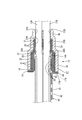
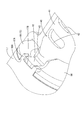
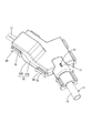
- top view which shows the sealing structure and sealing member of the multi-core cable which concern on one Embodiment
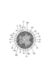
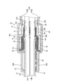
- Bottom view showing the sealing structure and sealing member of a multi-core cable III-III sectional view in FIG. IV-IV sectional view in FIG.
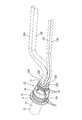
- Front view showing seal member Sectional view taken along line VI-VI in FIG. Sectional view taken along line VII-VII in FIG.
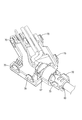
- FIG. 1 Perspective view showing rubber stopper Top view showing rubber stopper Front view showing rubber stopper Rear view showing rubber stopper Perspective view showing a cap Rear view showing cap
- FIG. 1 Perspective view showing rubber stopper Top view showing rubber stopper Front view showing rubber stopper Rear view showing rubber stopper Perspective view showing a cap Rear view showing cap
- FIG. 1 Perspective view showing rubber stopper Top view showing rubber stopper Front view showing rubber stopper Rear view showing rubber stopper Perspective view showing a cap Rear view showing cap
- FIG. 1 Perspective view showing rubber stopper Top view showing rubber stopper Front view showing rubber stopper Rear view showing rubber stopper Perspective view showing a cap Rear view showing cap
- FIG. 1 Perspective view showing rubber stopper Top view showing rubber stopper Front view showing rubber stopper Rear view showing rubber stopper Perspective view showing a cap Rear view showing cap
- FIG. 1 Perspective view showing rubber stopper Top view showing rubber stopper Front view showing rubber stopper Rear view showing rubber stopper Perspective view showing a cap Rear view showing cap
- FIG. 1 Perspective view showing rubber stop
- FIGS. 1 to 26 One embodiment will be described with reference to FIGS. 1 to 26.
- the present embodiment can be used, for example, for a wire harness for an electric parking brake mounted on a vehicle (not shown).
- the right side in FIG. 1 is the front and the left side is the rear.
- the upper side in FIG. 3 is the upper side, and the lower side is the lower side.
- symbol may be attached
- the multi-core cable 11 As shown in FIG. 3 to FIG. 4 and FIG. 16 to FIG. 18, the multi-core cable 11 according to the present embodiment has a plurality of electric wires 13A, 13B, 13C, and 13D (four in the present embodiment) combined with insulation.
- the structure is surrounded by a resin sheath 14.
- the electric wires 13A, 13B, 13C, and 13D have a configuration in which the outer periphery of a metal core wire (not shown) is covered with a synthetic resin insulating coating (not shown).
- the cross-sectional shape of the multicore cable 11 is circular.
- the electric wires 13A, 13B, 13C, and 13D are referred to as the electric wires 13 when described without distinction.
- the four electric wires 13A, 13B, 13C, and 13D include two types of electric wires 13A, 13B, 13C, and 13D having different outer diameter dimensions.
- a first electric wire 13A and a second electric wire 13B connected to a motor for an electric parking brake, a third electric wire 13C for an anti-lock brake system sensor, and a fourth electric wire 13D are included.
- the cross-sectional shapes of the first electric wire 13A, the second electric wire 13B, the third electric wire 13C, and the fourth electric wire 13D are circular.
- the outer diameter of the first electric wire 13A and the second electric wire 13B is set larger than the outer diameter of the third electric wire 13C and the fourth electric wire 13D.
- the outer diameter of the first electric wire 13A and the outer diameter of the second electric wire 13B are set to be the same.
- the outer diameter dimension of the third electric wire 13C and the outer diameter dimension of the fourth electric wire 13D are set to be the same.
- a first electric wire 13A, a second electric wire 13B, a third electric wire 13C, and a fourth electric wire 13D are led out from the end portion 14A of the sheath 14 of the multicore cable 11 and branched.
- seal member 10 As shown in FIGS. 1 to 4, in the end portion 14A of the sheath 14 of the multi-core cable 11, there is a region where the first electric wire 13A, the second electric wire 13B, the third electric wire 13C, and the fourth electric wire 13D are branched.
- a seal member 10 is attached.
- the seal member 10 prevents liquid such as water and oil from entering the sheath 14 from the end portion 14A of the sheath 14.
- the seal member 10 includes a rubber plug 15 attached to the end portion 14A of the sheath 14, a guide member 16 attached to the inside of the rubber plug 15, a cap 17 fitted to the rubber plug 15, and a portion close to the end portion of the sheath 14. , And a caulking member 40 that is externally fitted along with the rubber plug 15.
- a rubber plug 15 is attached to the end portion 14 ⁇ / b> A of the sheath 14.
- the rubber plug 15 has a sheath outer fitting portion 18 that is fitted on the end portion 14 ⁇ / b> A of the sheath 14.
- the sheath outer fitting portion 18 is formed in a hood shape that opens toward the rear side (left side in FIG. 3).
- the sheath outer fitting portion 18 is formed in a substantially cylindrical shape in a natural state.
- a flange portion 19 protruding outward in the radial direction of the sheath outer fitting portion 18 is formed at the rear edge of the sheath outer fitting portion 18 (see FIGS. 8 and 9).
- a part of the flange portion 19 is provided with a cutout portion 19A for passing an extension piece 17A of the cap 17 described later (see FIGS. 10 and 11).
- a plurality of sheath side lips 20 projecting inward are annularly provided along the circumferential direction of the sheath outer fitting portion 18 on the inner circumference of the sheath outer fitting portion 18. Is formed.
- the sheath side lip 20 is in close contact with the outer periphery of the sheath 14 in a state where the sheath outer fitting portion 18 is fitted on the end portion 14 ⁇ / b> A of the sheath 14. Thereby, the gap between the rubber plug 15 and the sheath 14 is sealed.
- the first electric wire 13 ⁇ / b> A, the second electric wire 13 ⁇ / b> B, the third electric wire 13 ⁇ / b> C, and the fourth electric wire are disposed at the front end (right side in FIG. 3) of the rubber plug 15.
- An electric wire penetrating portion 21 having a plurality of (four in this embodiment) through holes 22A, 22B, 22C, and 22D through which each of the electric wires 13D passes is provided.
- the plurality of through holes 22A, 22B, 22C, and 22D are penetrated by the first through hole 22A through which the first electric wire 13A passes, the second through hole 22B through which the second electric wire 13B passes, and the third electric wire 13C.
- the cross-sectional shape of the wire penetration portion 21 is formed in a trapezoidal shape with rounded corners.
- the cross-sectional shape of the wire penetrating portion 21 includes a long side 23 extending in the vertical direction, a short side 24 parallel to the long side 23 and shorter than the long side 23, an end of the long side 23, and an end of the short side 24. And two hypotenuses 25 connecting the sections.
- a first through hole 22A and a second through hole 22B are formed side by side along the direction in which the long side 23 extends (vertical direction) at a position near the long side 23. Further, in the wire penetration part 21, a third through hole 22 ⁇ / b> C and a fourth through hole 22 ⁇ / b> D are formed side by side along the direction (vertical direction) in which the short side 24 extends at a position near the short side 24.
- the inner diameter of the first through hole 22A is slightly larger than the outer diameter of the first electric wire 13A.
- a first electric wire side lip 26A (an example of an electric wire side lip) that is in close contact with the outer periphery of the first electric wire 13A is provided in the first through hole 22A. It is formed in an annular shape along the circumferential direction.
- the first electric wire side lip 26A is in close contact with the outer periphery of the first electric wire 13A in a state where the first electric wire 13A is penetrated into the first through hole 22A. Thereby, the space between the first electric wire 13A and the rubber plug 15 is sealed.
- the inner diameter dimension of the second through hole 22B is slightly larger than the outer diameter dimension of the second electric wire 13B.
- a second electric wire side lip 26B (an example of an electric wire side lip) that is in close contact with the outer periphery of the second electric wire 13B is provided in the second through hole 22B. It is formed in an annular shape along the circumferential direction.
- the 2nd electric wire side lip 26B is closely_contact
- the inner diameter dimension of the third through hole 22C is formed to be slightly larger than the outer diameter dimension of the third electric wire 13C.
- a third electric wire side lip 26C (an example of an electric wire side lip) that is in close contact with the outer periphery of the third electric wire 13C is provided. It is formed in an annular shape along the circumferential direction.
- the third electric wire side lip 26C comes into close contact with the outer periphery of the third electric wire 13C in a state where the third electric wire 13C is penetrated into the third through hole 22C. Thereby, the space between the third electric wire 13C and the rubber plug 15 is sealed.
- the inner diameter dimension of the fourth through hole 22D is formed to be slightly larger than the outer diameter dimension of the fourth electric wire 13D.
- a fourth electric wire side lip 26D (an example of the electric wire side lip) that is in close contact with the outer periphery of the fourth electric wire 13D is provided on the inner periphery of the fourth through hole 22D. It is formed in an annular shape along the circumferential direction. The fourth electric wire side lip 26D is in close contact with the outer periphery of the fourth electric wire 13D in a state in which the fourth electric wire 13D is passed through the fourth through hole 22D. Thereby, the space between the fourth electric wire 13D and the rubber plug 15 is sealed.
- the rubber plug 15 includes the first electric wire 13 ⁇ / b> A, the first electric wire 13 ⁇ / b> A, and the first electric wire 13 ⁇ / b> A at the position inside the sheath outer fitting portion 18 and between the sheath side lip 20 and the electric wire penetration portion 21.
- a guide member 16 described later having a plurality of (four in this embodiment) guide holes 38A, 38B, 38C, and 38D through which the two electric wires 13B, the third electric wires 13C, and the fourth electric wires 13D are inserted is held.
- a holding portion 28 is formed.
- Cap 17 As shown in FIGS. 3 and 4, a synthetic resin cap 17 is fitted on the rubber plug 15. The cap 17 opens toward the rear side (left side in FIG. 3), and is externally fitted to the rubber plug 15 from the front side (right side in FIG. 3).
- the opening side (left side in FIG. 3) of the cap 17 is a large-diameter portion 30 that is fitted on the sheath fitting portion 18 of the rubber plug 15. As shown in FIGS. 6 and 13, the cross-sectional shape of the large-diameter portion 30 is formed in a circular shape following the outer shape of the sheath outer fitting portion 18.
- the inner periphery of the large-diameter portion 30 is in close contact with a plurality of (three in this embodiment) large-diameter portion side lips 31 formed on the outer periphery of the sheath outer fitting portion 18. It has become. As shown in FIGS. 8 and 9, the large-diameter portion side lip 31 protrudes outward on the outer peripheral surface of the sheath outer fitting portion 18 and is formed along the circumferential direction of the sheath outer fitting portion 18. .
- a plurality of (two in this embodiment) rubber plugs having a rib shape extending along the opening direction of the cap 17 is provided inside the large-diameter portion 30 of the cap 17.
- a locking portion 32 is formed.
- the two rubber stoppers 32 are formed at positions facing each other on the inner periphery of the large diameter portion 30.
- a plurality (two in this embodiment) of rubber stoppers 32 are inserted into the outer periphery of the sheath outer fitting portion 18 and the holding portion 28 of the rubber stopper 15.
- Two stopper portions 33 for rubber plugs are formed in a groove shape along the extending direction of the sheath outer fitting portion 18.
- Each of the two rubber stopper locking portions 33 is formed at a position corresponding to each of the two rubber stopper locking portions 32 formed in the large diameter portion 30.
- the rubber plug 15 is locked with respect to the cap 17 by the rubber plug locking portion 32 of the large diameter portion 30 and the rubber plug locked portion 33 of the sheath outer fitting portion 18 being locked. The rotation in the circumferential direction is suppressed.
- the large-diameter portion 30 is connected to the sheath external fitting portion 18 of the rubber plug 15 while the large-diameter portion 30 of the cap 17 is externally fitted to the sheath external fitting portion 18.
- the fitting portion 18 is pressed inward in the radial direction.
- the sheath outer fitting portion 18 is pressed against the outer periphery of the sheath 14 from the outside.
- the sheath-side lip 20 of the sheath outer fitting portion 18 is securely brought into close contact with the outer periphery of the sheath 14.
- An extension piece 17A extending toward the rear side is provided on a part (lower end portion) of the opening edge on the rear side of the cap 17 (large diameter portion 30) (see FIGS. 2 and 24). ).
- the extending piece 17A extends to the sheath 14 side (rear side) through the notch 19A of the rubber plug 15 described above. Accordingly, the cap 17 is prevented from rotating with respect to the rubber plug 15 in the circumferential direction of the rubber plug 15.
- the portion other than the extending piece 17A is in contact with the flange portion 19 of the rubber plug 15 (see FIG. 4).
- the extending piece 17 ⁇ / b> A has a curved surface whose inner circumferential surface is flush with the inner circumferential surface of the large-diameter portion 30, and whose outer circumferential surface is flush with the outer circumferential surface of the large-diameter portion 30.
- the extension dimension of the extension piece 17A is substantially equal to the sum of the thickness dimension of the flange portion 19 and the plate thickness of the fitting portion 44 (locking piece 43) of the caulking member 40 described later.
- the leading edge in the exit direction protrudes from the flange portion 19 of the rubber plug 15 to the sheath 14 side (rear side) (see FIGS. 2 and 24).
- the distal end surface in the extending direction of the extending piece 17A is cut out in a concave shape from the sheath 14 side (rear side), and a locking piece 43 (fitting portion 44) of the caulking member 40 described later is fitted. It is set as the receiving recessed part 17B.
- the notch depth of the receiving recess 17B is substantially equal to the plate thickness of a locking piece 43 (fitting portion 44) of the caulking member 40 described later.
- a small-diameter portion 34 that is externally fitted to the wire penetration portion 21 of the rubber plug 15 is provided in front of the large-diameter portion 30 (right side in FIG. 3) of the cap 17. .
- the outer diameter dimension of the small diameter part 34 is set smaller than the outer diameter dimension of the large diameter part 30.
- the cross-sectional shape of the small diameter portion 34 is formed in a trapezoidal shape with rounded corners following the outer shape of the wire penetration portion 21.
- the inner periphery of the small diameter portion 34 comes into close contact with a plurality of (three in this embodiment) small diameter portion lips 35 formed on the outer periphery of the wire penetration portion 21. Yes.
- the small-diameter portion side lip 35 protrudes outward on the outer peripheral surface of the wire penetration portion 21 and is formed along the circumferential direction of the wire penetration portion 21.
- the small diameter portion 34 of the cap 17 in a state where the small diameter portion 34 of the cap 17 is externally fitted to the electric wire penetration portion 21 of the rubber plug 15, the small diameter portion 34 changes the electric wire penetration portion 21 and the diameter of the electric wire penetration portion 21. It pushes inward in the direction. Thereby, the electric wire penetration part 21 is compressed from the outside. As a result, the first to fourth electric wire side lips 26A, 26B, 26C, and 26D formed on the inner periphery of the first to fourth through holes 22A, 22B, 22C, and 22D are connected to the first to fourth electric wires 13A and 13B. , 13C, and 13D are securely in close contact with the outer peripheries.
- the cap 17 includes a back wall 36 on the front side (right side in FIG. 3) of the small diameter portion 34.
- the first lead-out hole through which the first electric wire 13 ⁇ / b> A, the second electric wire 13 ⁇ / b> B, the third electric wire 13 ⁇ / b> C, and the fourth electric wire 13 ⁇ / b> D are led out from the cap 17.
- 37A, a second outlet hole 37B, a third outlet hole 37C, and a fourth outlet hole 37D are formed through the back wall 36.
- the rubber plug 15 is positioned relative to the cap 17.
- each of the first to fourth through holes 22A, 22B, 22C, 22D formed in the rubber plug 15 and the first to fourth lead-outs formed in the cap 17 are obtained.
- the holes 37A, 37B, 37C and 37D are aligned with each other.
- first through hole 22A and the first outlet hole 37A are aligned
- second through hole 22B and the second outlet hole 37B are aligned
- third through hole 22C and the third outlet hole 37C are aligned
- fourth through hole 22D and the fourth lead-out hole 37D are aligned with each other.
- the cap 17 is formed with two locking projections 50 ⁇ / b> A and 50 ⁇ / b> B that protrude outward in the radial direction of the small diameter portion 34 from the outer surface of the small diameter portion 34.
- the two locking projections 50A and 50B one locking projection 50A protrudes from the long side 23 side of the small diameter portion 34, and the other locking projection 50B protrudes from the short side 24 side of the small diameter portion 34.
- the two locking projections 50A and 50B have a plate shape, and have a generally rectangular shape as a whole.
- the cap 17 is formed with an anti-rotation protrusion 51 protruding upward on the outer periphery of the large diameter portion 30.
- the anti-rotation protrusion 51 has a rib shape extending in the extending direction of the large-diameter portion 30 (left-right direction in FIG. 1).
- the guide member 16 is made of synthetic resin, and as shown in FIGS. 6 and 14, a first guide hole 38A through which the first electric wire 13A is inserted and a second guide hole 38B through which the second electric wire 13B is inserted.
- the third guide hole 38C through which the third electric wire 13C is inserted and the fourth guide hole 38D through which the fourth electric wire 13D is inserted are penetrated.
- a plurality of (four in this embodiment) guide member locking portions 29 projecting inward are formed on the inner periphery of the holding portion 28 of the rubber plug 15. .
- a plurality (four in this embodiment) of guide member locking portions 39 into which each of the four guide member locking portions 29 is fitted are recessed from the outer periphery of the guide member 16. Is formed.
- Each of the four guide member locking portions 39 formed on the guide member 16 is formed at a position corresponding to each of the four guide member locking portions 29 formed on the rubber plug 15.
- Each of the four guide member locking portions 29 formed on the holding portion 28 of the rubber plug 15 engages with each of the four guide member locked portions 39 formed on the guide member 16.
- the guide member 16 is held in a state in which rotation of the guide member 16 in the circumferential direction of the guide member 16 with respect to the rubber plug 15 is suppressed. Thereby, relative positioning of the rubber stopper 15 and the guide member 16 is made.
- the first to fourth through holes 22A, 22B, 22C, 22D of the rubber plug 15 and the first to fourth guide holes 38A, 38B, 38C and 38D are matched with each other.
- first through hole 22A and the first guide hole 38A are aligned
- second through hole 22B and the second guide hole 38B are aligned
- third through hole 22C and the third guide hole 38C are aligned
- fourth through hole 22D and the fourth guide hole 38D are aligned with each other.
- a caulking member 40 is attached to the sheath 14 along with the rubber plug 15 on the rear side of the rubber plug 15 near the end portion 14 ⁇ / b> A.
- the caulking member 40 is made of metal and has a main body 41 having a substantially cylindrical shape with a C-shaped cross section (see FIG. 15). Both end edges in the circumferential direction of the main body 41 are formed in a wave shape (see FIG. 1).
- the main body 41 has elasticity in the opening / closing direction.
- Two long holes 42 extending in the circumferential direction are provided in the central portion of the main body 41 in the circumferential direction so as to penetrate the plate surface in the length direction of the main body 41 (see FIG. 2). ).
- the main body portion 41 is formed so as to extend toward the front (right side in FIG. 2) at the central portion in the circumferential direction on one end side (front side) in the length direction.
- a locking piece 43 is provided.
- the locking piece 43 is extended along the main body 41, and then the distal end side is bent outward in an L shape, and the distal end is provided on the extending piece 17A of the cap 17 described above.
- the fitting portion 44 has a width that can be fitted into the receiving recess 17B.
- the holder 52 includes a lower holder 52A and an upper holder 52B assembled to the lower holder 52A.
- the lower holder 52A includes a bottom wall and a side wall that rises upward from a side edge of the bottom wall.
- a motor wire outlet 55A from which the first electric wire 13A and the second electric wire 13B are led out and a sensor electric wire outlet 56A from which the third electric wire 13C and the fourth electric wire 13D are led out are semicircular. It is depressed and opened.
- a spare outlet for a wire (not shown) connected to a device different from the motor or the sensor is provided on a side wall different from the side wall where the motor wire outlet 55A and the sensor wire outlet 56A are formed.
- 57A is depressed in a semicircular shape and opened.
- a plurality of holding grooves 58 for holding a corrugated tube are formed on the inner peripheral surfaces of the motor electric wire outlet 55A, the sensor electric wire outlet 56A, and the auxiliary outlet 57A.
- an extended portion 59A that protrudes outward is formed on a side wall different from that in which the motor wire outlet 55A, the sensor wire outlet 56A, and the preliminary outlet 57A are formed.
- the cross-sectional shape of the extending portion 59A is formed in a substantially semicircular shape.
- the distal end side of the extending portion 59A is a caulking member holding portion 60 that holds the caulking member 40 in a state where the sheath 14 is caulked.
- the inner diameter dimension of the crimping member holding part 60 is set to a dimension in which the main body part 41 of the crimping member 40 in a state in which the sheath 14 is crimped is accommodated without rattling in the radial direction (see FIGS. 21 and 22). ).
- a holding rib 61 that protrudes inward and extends in the circumferential direction of the caulking member holding portion 60 is formed at the end edge portion of the caulking member holding portion 60.
- the holding rib 61 prevents the caulking member 40 from coming out of the caulking member holding portion 60 to the outside.
- the dimension of the crimping member holding portion 60 in the extending direction is such that the body portion 41 of the crimping member 40 is crimped to the sheath 14 and the fitting portion 44 is fitted to the receiving recess 17B of the cap 17.
- the size is set such that the fastening member 40 is accommodated without rattling in the extending direction.
- a cap holding portion 62 for holding the cap 17 is formed from the proximal end side of the extending portion 59A to a position slightly inside the extending portion 59A of the lower holder 52A.
- the large diameter part 30 of the cap 17 is accommodated in the base end side of the extending part 59A in the cap holding part 62.
- the size of the portion in which the large-diameter portion 30 is accommodated is set to a size in which the large-diameter portion 30 is accommodated without rattling in the radial direction (see FIGS. 21 and 22).
- a partition wall 63 protruding upward from the bottom wall is formed at a position inside the lower holder 52 ⁇ / b> A with respect to the side wall of the cap holding part 62, and a cap is formed in a region surrounded by the partition wall 63. 17 small-diameter portions 34 are accommodated.
- the partition wall 63 has a locking groove 64 into which the locking projections 50A and 50B are inserted at positions corresponding to the locking projections 50A and 50B of the cap 17 in a state where the cap 17 is housed inside the partition wall 63. It is formed extending downward from the upper edge of the partition wall 63.
- the locking projections 50A and 50B are inserted into the locking groove 64 in a state where the cap 17 is accommodated in the cap holding part 62. As a result, the locking protrusions 50A and 50B come into contact with the inner surface of the locking groove 64 from the thickness direction of the locking protrusions 50A and 50B, so that the relative positions of the cap 17 and the holder 52 are shifted. This is suppressed (see FIG. 21).
- the locking groove 64 is formed in the partition 63 at a position slightly inside the side wall of the lower holder 52A. Thereby, the force applied to the cap 17 is received by the side wall of the lower holder 52A.
- the width dimension of the locking groove 64 is set to be the same as or slightly larger than the thickness dimension of the locking protrusions 50A and 50B.
- An inclined surface for guiding the locking protrusions 50 ⁇ / b> A and 50 ⁇ / b> B is formed on the opening edge portion of the locking groove 64 so as to expand the diameter upward.
- the bottom wall of the lower holder 52A has a plurality of first to fourth electric wires 13A led out from the first through fourth through holes 22A, 22B, 22C, 22D of the rubber plug 15.
- 13B, 13C, 13D are formed with a first electric wire routing portion 65A and a second electric wire routing portion 65B for guiding them along a predetermined routing route.
- the first electric wire arrangement portion 65A and the second electric wire arrangement portion 65B are formed in a wall shape that rises upward from the bottom wall.
- the second electric wire routing portion 65B is provided on the side close to the sensor electric wire outlet 56A.
- the first electric wire routing portion 65A and the second electric wire routing portion 65B are formed by gently bending from a position near the cap holding portion 62 to a position near the motor wire outlet 55A.
- 65 A of 1st electric wire routing parts and the 2nd electric wire routing part 65B are formed in the substantially S shape seeing from upper direction.
- the first electric wire 13A and the second electric wire 13B are accommodated between the first electric wire arrangement portion 65A and the second electric wire arrangement portion 65B.
- the first electric wire 13A and the second electric wire 13B are routed along the routing route from the cap 17 to the motor wire outlet 55A.
- a guide protrusion 66 extending toward the sensor electric wire outlet 56A is formed at a position in the vicinity of the sensor electric wire outlet 56A.
- the third electric wire 13C and the fourth electric wire 13D led out from the cap 17 are guided by coming into contact with the second electric wire routing portion 65B and the guide projection 66, and reach from the cap 17 to the sensor electric wire outlet 56A. It is routed along the route.
- a bracket 67 is formed on the side wall of the lower holder 52A so as to protrude downward (see FIG. 19).
- a bolt insertion hole 68 is formed through the bracket 67.
- a bolt (not shown) is inserted into the bolt insertion hole 68 and screwed to the vehicle, whereby the holder 52 is fixed to the vehicle.
- the upper holder 52 ⁇ / b> B includes an upper wall and a side wall that extends downward from an edge of the upper wall.
- a plurality of lock receiving portions 70 are formed at positions corresponding to the plurality of lock portions 69 formed on the side wall of the lower holder 52A.
- the lower holder 52A and the upper holder 52B are assembled by elastically engaging the lock portion 69 and the lock receiving portion 70 (see FIG. 25).
- the motor wire outlet 55A, the sensor wire outlet 56A, the preliminary outlet 57A, and the extension of the lower holder 52A A motor wire outlet 55B, a sensor wire outlet 56B, a preliminary outlet 57B, and an extending portion 59B are formed at positions corresponding to the portion 59A.
- the extension portion 59B of the upper holder 52B is formed with a detent hole 71 penetrating at a position corresponding to the detent protrusion 51 of the cap 17 in a state where the cap 17 is accommodated in the cap holding portion 62. (See FIG. 19 and FIG. 25).
- the anti-rotation protrusion 51 is inserted into the anti-rotation hole 71, and the anti-rotation protrusion 51 contacts the inner peripheral surface of the anti-rotation hole 71, so that the cap 17 has a large diameter portion of the cap 17 in the cap holding portion 62. The rotation in the circumferential direction of 30 is suppressed.
- the cap 17 (the seal member 10) can be reliably aligned with respect to the holder 52 in the vertical direction.
- the first to fourth electric wires 13A, 13B, 13C, 13D led out from the cap 17, and the first electric wire routing portion 65A and the second electric wire routing portion 65B can be easily aligned. .
- the caulking member holding portion 60 and the cap holding portion 62 of the same form are located at positions corresponding to the caulking member holding portion 60, the cap holding portion 62, and the locking groove 64 of the lower holder 52A.
- a locking groove 64 is formed.
- the sheath 14 of the multicore cable 11 is peeled off by a known method.
- the first to fourth electric wires 13A, 13B, 13C, and 13D are led out from the end portion 14A of the sheath 14.
- the first to fourth electric wires 13A, 13B, 13C, and 13D are inserted into the first to fourth guide holes 38A, 38B, 38C, and 38D of the guide member 16, respectively.
- the fourth electric wire 13D is inserted through 38D.
- the first to fourth electric wires 13A, 13B, 13C, and 13D are inserted into the first to fourth through holes 22A, 22B, 22C, and 22D of the rubber plug 15, respectively.
- the first electric wire 13A is inserted through the first through hole 22A
- the second electric wire 13B is inserted through the second through hole 22B
- the third electric wire 13C is inserted through the third through hole 22C
- the fourth through hole is inserted.
- the fourth electric wire 13D is inserted through 22D.
- the rubber stopper 15 is moved to the position of the guide member 16.
- the first to fourth through holes 22A, 22B, 22C, 22D of the rubber plug 15 and the first to fourth guide holes 38A, 38B, 38C, 38D of the guide member 16 are aligned with each other.
- the relative positions of the rubber plug 15 and the guide member 16 are adjusted so as to be arranged.
- the guide member 16 side locking portion of the rubber plug 15 and the guide member 16 side locked portion of the guide member 16 are locked.
- each of the first to fourth through holes 22A, 22B, 22C, and 22D of the rubber plug 15 is aligned with each of the first to fourth guide holes 38A, 38B, 38C, and 38D of the guide member 16.
- the guide member 16 is held by the holding portion 28 of the rubber plug 15.
- the rubber plug 15 is moved to the end portion 14 ⁇ / b> A of the sheath 14, and the sheath outer fitting portion 18 of the rubber plug 15 is externally fitted to the end portion 14 ⁇ / b> A of the sheath 14.
- the first to fourth electric wires 13A, 13B, 13C, and 13D are inserted into the first to fourth lead-out holes 37A, 37B, 37C, and 37D of the cap 17, respectively.
- the first electric wire 13A is inserted through the first outlet hole 37A
- the second electric wire 13B is inserted through the second outlet hole 37B
- the third electric wire 13C is inserted through the third outlet hole 37C
- the fourth outlet hole is inserted.
- the fourth electric wire 13D is inserted through 37D.
- the cap 17 is moved to the position of the rubber plug 15 fitted on the end 14 ⁇ / b> A of the sheath 14.
- the first to fourth through holes 22A, 22B, 22C, 22D of the rubber plug 15 and the first to fourth outlet holes 37A, 37B, 37C, 37D of the cap 17 are aligned with each other.
- the relative positions of the rubber plug 15 and the cap 17 are adjusted so that In the above state, the rubber plug 15 side locking portion of the cap 17 and the rubber plug 15 side locked portion of the rubber plug 15 are locked.
- the first to fourth through holes 22A, 22B, 22C, 22D of the rubber plug 15 and the first to fourth outlet holes 37A, 37B, 37C, 37D of the cap 17 are aligned with each other.
- the cap 17 is fitted on the rubber plug 15. Thereafter, the cap 17 is pushed in until it comes into contact with the flange portion 19 of the rubber plug 15 (see FIG. 18).
- the extended piece 17A of the cap 17 passes through a notch 19A provided in the flange 19 of the rubber plug 15, and its tip protrudes rearward from the back of the flange 19 (FIG. 24). reference).
- the body portion 41 is attached to the sheath 14 while performing alignment so that the fitting portion 44 of the caulking member 40 is fitted into the receiving concave portion 17B of the cap 17.
- the main body 41 is attached to the sheath 14 while being elastically deformed, and in the state of being attached to the sheath 14, the sheath 14 is crimped toward the inside. Thereby, the caulking member 40 is fixed relative to the sheath 14 and the electric wire 13 in the sheath 14 is held so as not to move.
- the seal member 10 according to the present embodiment is completed, and the seal structure 12 of the multicore cable 11 is completed (see FIGS. 1 to 4).
- the caulking member 40 with the sheath 14 caulked is placed on the caulking member holding part 60 of the lower holder 52 ⁇ / b> A, and the anti-rotation protrusion of the cap 17 is placed on the cap holding part 62.
- the cap 17 is placed with the posture 51 facing upward.
- the locking protrusions 50A and 50B of the cap 17 are inserted into the locking groove 64 from above.
- the first electric wire 13A and the second electric wire 13B led out from the cap 17 are arranged between the first electric wire routing portion 65A and the second electric wire routing portion 65B, and are distributed to the motor electric wire outlet 55A.
- the third electric wire 13C and the fourth electric wire 13D led out from the cap 17 are routed to the sensor electric wire outlet 56A while being along the second electric wire routing portion 65B and the guide protrusion 66.
- the upper holder 52B is assembled to the lower holder 52A from above.
- the upper holder 52B and the lower holder 52A are assembled together by elastically engaging the lock portion 69 and the lock receiving portion 70 (see FIG. 25).
- the anti-rotation protrusion 51 of the cap 17 is fitted into the anti-rotation hole 71 of the upper holder 52B.
- the cap 17 is fitted to the rubber plug 15 while pressing the inside, and the rubber plug locking portion. 32 is locked to the locked portion 33 for the rubber plug, and the extension piece 17A is passed through the cutout portion 19A, so that the rotation is prevented, so that the cap 17 and the rubber plug 15 are relative to each other. The position is maintained.
- the crimping member 40 is crimping the sheath 14, the relative position between the crimping member 40 and the sheath 14 is maintained. Further, in the portion of the sheath 14 that is crimped by the crimping member 40 (main body portion 41), the plurality of electric wires 13 are held by the crimping member 40 so as not to move within the sheath 14.
- the cap 17 and the caulking member 40 are held at their relative positions by fitting the fitting portion 44 of the locking piece 43 into the receiving recess 17B, the rubber plug 15 and the sheath 14, and eventually The relative positions of the rubber plug 15 and the electric wire 13 are indirectly held. Therefore, even when a strong force such as twisting acts on the sheath 14 from the outside, the sealing property between the electric wire 13 and the rubber plug 15 can be maintained in a good state.
- the locking structure between the crimping member 40 and the cap 17 is such that the fitting portion 44 of the locking piece 43 extending from the main body portion 41 of the crimping member 40 is fitted into the receiving recess 17 ⁇ / b> B provided in the cap 17. Since it is a simple structure that can be simply inserted, a complicated locking structure is unnecessary, and the positioning is simple and the workability is excellent. Further, with such a configuration, the caulking member 40 and the cap 17 are reliably prevented from rotating, and the electric wire 13 is prevented from being twisted with respect to the rubber plug 15.
- the sealing performance between the plurality of electric wires 13 led out from the multicore cable 11 and the rubber plug 15 can be enhanced.
- the cap 17 and the caulking member 40 are prevented from rotating by fitting the fitting portion 44 of the locking piece 43 of the caulking member 40 into the receiving recess 17B provided in the cap 17.
- a configuration may be adopted in which a fitting portion is provided on the cap side and a receiving recess for receiving the fitting portion is provided on the caulking member side.
- a locking hole is provided in one of the cap and the caulking member, and a locking portion that can be locked with the locking hole is provided in the other.
- the relative position in the extending direction of the sheath may also be held.
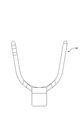
- the main body 41 of the caulking member 40 has a cylindrical shape with elastic C-section, but the main body is formed on the outer periphery of the sheath 14 as shown in FIG. It is good also as a form which crimps so that it may wind and crimps a sheath.
- the caulking member 40 is made of metal, but may be resinous, for example.
- the cap 17 and the rubber plug 15 are prevented from rotating by providing the rubber plug locking portion 32 and the rubber plug locked portion 33, but these are omitted. May be.
- the plurality of electric wires arranged in the multi-core cable 11 may be two to three, or five or more.
- the plurality of electric wires are configured to include electric wires having two types of outer diameters, but are not limited thereto, and may be configured to include electric wires having three or more types of outer diameters. Alternatively, all of the outer diameter dimensions of the plurality of electric wires may be the same.
- the guide member 16 can be omitted.
- the electric wire may be a shielded electric wire.
- the electric wire may be a stranded wire provided with a core wire in which a plurality of fine metal wires are twisted together, or may be a so-called single core wire having a metal rod as a core wire.
- arbitrary electric wires can be appropriately selected as necessary.
- the multi-core cable 11 may be a so-called cabtyre cable, or may be a multi-core shielded electric wire in which the outer periphery of a plurality of electric wires is surrounded by a shield layer.
- any multi-core cable 11 can be appropriately selected as necessary.
- any liquid such as water, oil, organic solvent, or the like can be sealed as necessary.
- the seal member 10 is assembled by assembling the guide member 16, the rubber plug 15, the cap 17, and the caulking member 40 in this order to the multicore cable 11 with the sheath 14 peeled off. And the sealing structure 12 of the multicore cable 11 is formed.
- the present invention is not limited to this, and a plurality of wires of the multicore cable 11 in which the sheath 14 is peeled off from the seal member 10 assembled in advance.
- the multi-core cable 11 and the seal member 10 may be assembled by inserting the cable.
- a protrusion 60A that fits into the long hole 42 is provided at a position corresponding to the long hole 42 in the state where the crimping member 40 is accommodated in the crimping member holding part 60 of the lower holder 52A. It is good also as a structure which hold
- Seal member 11 Multi-core cable 12: Seal structure 13: Electric wire 14: Sheath 15: Rubber plug 16: Guide member 17: Cap 17A: Extension piece (locked portion) 17B: Receiving recess (locked portion) 18: Sheath outer fitting part 19: Flange part 19A: Notch 21: Electric wire penetration part 28: Holding part 30: Large diameter part 34: Small diameter part 40: Clamping member 41: Main body part 43: Locking piece (locking part) ) 44: Fitting portion (locking portion)
Landscapes
- Installation Of Indoor Wiring (AREA)
- Connector Housings Or Holding Contact Members (AREA)
Abstract
La présente invention comprend : un câble multiconducteur (11) dans lequel des premier à quatrième fils électriques (13A, 13B, 13C, 13D) sont entourés par une gaine (14) et les premier à quatrième fils électriques (13A, 13B, 13C, 13D) sont faits sortir par une partie d'extrémité (14A) ; un bouchon en caoutchouc (15) à travers lequel chacun des premier à quatrième fils électriques (13A, 13B, 13C, 13D) est fait passer et qui est réglé sur la partie d'extrémité (14A) de la gaine (14) ; un chapeau (17) pour pousser le bouchon en caoutchouc (15) vers l'intérieur, le chapeau (17) étant réglé sur le bouchon en caoutchouc (15) ; et un élément de sertissage (40) disposé en alignement avec le bouchon en caoutchouc (15) et serti sur la gaine (14) ; et la présente invention est configurée de manière que l'élément de sertissage (40) comporte une pièce de verrouillage (43) et une partie de réglage (44), le chapeau (17) comporte une pièce d'extension (17A) et un évidement de réception (17B), et la partie de réglage (44) de la pièce de verrouillage (43) et l'évidement de réception (17B) de la pièce d'extension (17A) soient verrouillés, moyennant quoi l'élément de sertissage (40) et le bouchon en caoutchouc (15) sont maintenus en position l'un par rapport à l'autre.
Priority Applications (2)
| Application Number | Priority Date | Filing Date | Title |
|---|---|---|---|
| US15/538,417 US9837806B1 (en) | 2014-12-25 | 2015-12-15 | Seal structure for multicore cable, and seal member |
| CN201580069822.8A CN107112740B (zh) | 2014-12-25 | 2015-12-15 | 多芯缆线的密封结构及密封部件 |
Applications Claiming Priority (2)
| Application Number | Priority Date | Filing Date | Title |
|---|---|---|---|
| JP2014-262482 | 2014-12-25 | ||
| JP2014262482A JP6210330B2 (ja) | 2014-12-25 | 2014-12-25 | 多芯ケーブルのシール構造、及び、シール部材 |
Publications (1)
| Publication Number | Publication Date |
|---|---|
| WO2016104242A1 true WO2016104242A1 (fr) | 2016-06-30 |
Family
ID=56150267
Family Applications (1)
| Application Number | Title | Priority Date | Filing Date |
|---|---|---|---|
| PCT/JP2015/085027 Ceased WO2016104242A1 (fr) | 2014-12-25 | 2015-12-15 | Structure d'étanchéité pour câble multiconducteur, et élément d'étanchéité |
Country Status (4)
| Country | Link |
|---|---|
| US (1) | US9837806B1 (fr) |
| JP (1) | JP6210330B2 (fr) |
| CN (1) | CN107112740B (fr) |
| WO (1) | WO2016104242A1 (fr) |
Cited By (1)
| Publication number | Priority date | Publication date | Assignee | Title |
|---|---|---|---|---|
| US20220131357A1 (en) * | 2020-10-22 | 2022-04-28 | Quanta Computer Inc. | Cable-Gland System For An Electronic Chassis Providing Enhanced Sealing Functionality |
Families Citing this family (4)
| Publication number | Priority date | Publication date | Assignee | Title |
|---|---|---|---|---|
| JP6686833B2 (ja) | 2016-10-12 | 2020-04-22 | 住友電装株式会社 | 導電路 |
| US10591090B2 (en) | 2017-12-28 | 2020-03-17 | Nexans | Top drive service loop clamp with torsional relief |
| US10801645B2 (en) | 2017-12-28 | 2020-10-13 | Nexans | Dynamic application cable assembly with adjustable armor clamp |
| US12095244B2 (en) * | 2019-09-24 | 2024-09-17 | Commscope Technologies Llc | Composite cable seal |
Citations (2)
| Publication number | Priority date | Publication date | Assignee | Title |
|---|---|---|---|---|
| JPH0452387U (fr) * | 1990-09-12 | 1992-05-01 | ||
| JP2010218777A (ja) * | 2009-03-13 | 2010-09-30 | Yazaki Corp | コネクタ |
Family Cites Families (10)
| Publication number | Priority date | Publication date | Assignee | Title |
|---|---|---|---|---|
| US3328746A (en) * | 1964-08-03 | 1967-06-27 | Amp Inc | Connector seal and support |
| US3913206A (en) * | 1973-06-01 | 1975-10-21 | Hughes Aircraft Co | Method for replacement of wire seal, electrical contact |
| US4527851A (en) * | 1984-05-14 | 1985-07-09 | Allied Corporation | Electrical connector assembly having an interfacial seal |
| JP2931203B2 (ja) * | 1994-03-24 | 1999-08-09 | 矢崎総業株式会社 | 防水コネクタ |
| JP3267240B2 (ja) | 1998-05-11 | 2002-03-18 | 住友電装株式会社 | 防水コネクタ |
| FR2782172B1 (fr) * | 1998-08-04 | 2001-11-30 | Pouyet Sa | Dispositif d'entree de cable a fibres optiques |
| CN201075651Y (zh) * | 2007-07-23 | 2008-06-18 | 中山圣马丁电子元件有限公司 | 电缆防水接头 |
| CN201323432Y (zh) * | 2008-12-06 | 2009-10-07 | 大庆油田有限责任公司 | 可分解密封电缆头 |
| CN201608491U (zh) * | 2009-12-22 | 2010-10-13 | 芜湖晶鑫灯饰有限公司 | 电线密封套 |
| CN103166163A (zh) * | 2011-12-14 | 2013-06-19 | 海洋王照明科技股份有限公司 | 电缆接头 |
-
2014
- 2014-12-25 JP JP2014262482A patent/JP6210330B2/ja not_active Expired - Fee Related
-
2015
- 2015-12-15 WO PCT/JP2015/085027 patent/WO2016104242A1/fr not_active Ceased
- 2015-12-15 US US15/538,417 patent/US9837806B1/en not_active Expired - Fee Related
- 2015-12-15 CN CN201580069822.8A patent/CN107112740B/zh not_active Expired - Fee Related
Patent Citations (2)
| Publication number | Priority date | Publication date | Assignee | Title |
|---|---|---|---|---|
| JPH0452387U (fr) * | 1990-09-12 | 1992-05-01 | ||
| JP2010218777A (ja) * | 2009-03-13 | 2010-09-30 | Yazaki Corp | コネクタ |
Cited By (2)
| Publication number | Priority date | Publication date | Assignee | Title |
|---|---|---|---|---|
| US20220131357A1 (en) * | 2020-10-22 | 2022-04-28 | Quanta Computer Inc. | Cable-Gland System For An Electronic Chassis Providing Enhanced Sealing Functionality |
| US11837860B2 (en) * | 2020-10-22 | 2023-12-05 | Quanta Computer Inc. | Cable-gland system for an electronic chassis providing enhanced sealing functionality |
Also Published As
| Publication number | Publication date |
|---|---|
| JP2016123224A (ja) | 2016-07-07 |
| CN107112740A (zh) | 2017-08-29 |
| JP6210330B2 (ja) | 2017-10-11 |
| US20170338641A1 (en) | 2017-11-23 |
| US9837806B1 (en) | 2017-12-05 |
| CN107112740B (zh) | 2019-04-02 |
Similar Documents
| Publication | Publication Date | Title |
|---|---|---|
| JP5862710B2 (ja) | シール部材 | |
| JP6210330B2 (ja) | 多芯ケーブルのシール構造、及び、シール部材 | |
| EP3142204B1 (fr) | Élément de scellement, et structure de scellement de câble multiconducteur | |
| JP5867613B2 (ja) | ワイヤハーネス | |
| US9905337B2 (en) | Sealing structure of multicore cable | |
| CN107251350B (zh) | 多芯电缆的密封结构 | |
| US10759359B1 (en) | Holding structure for cable | |
| JP6229699B2 (ja) | シールド導電路 | |
| CN108370146B (zh) | 多芯电缆的密封结构 | |
| WO2016104241A1 (fr) | Structure de joint d'étanchéité pour câble multiconducteur | |
| EP3376620B1 (fr) | Structure d'étanchéité pour câble, et organe d'étanchéité | |
| JP5440437B2 (ja) | 電線の端末構造 | |
| JP2013168257A (ja) | コネクタ及び増径電線の製造方法 | |
| JP6376107B2 (ja) | シール部材、及び多芯ケーブルのシール構造 | |
| JP6070467B2 (ja) | グロメット及びグロメット付ワイヤーハーネス |
Legal Events
| Date | Code | Title | Description |
|---|---|---|---|
| 121 | Ep: the epo has been informed by wipo that ep was designated in this application |
Ref document number: 15872811 Country of ref document: EP Kind code of ref document: A1 |
|
| WWE | Wipo information: entry into national phase |
Ref document number: 15538417 Country of ref document: US |
|
| NENP | Non-entry into the national phase |
Ref country code: DE |
|
| 122 | Ep: pct application non-entry in european phase |
Ref document number: 15872811 Country of ref document: EP Kind code of ref document: A1 |