WO2016104274A1 - 気体圧縮機 - Google Patents
気体圧縮機 Download PDFInfo
- Publication number
- WO2016104274A1 WO2016104274A1 PCT/JP2015/085193 JP2015085193W WO2016104274A1 WO 2016104274 A1 WO2016104274 A1 WO 2016104274A1 JP 2015085193 W JP2015085193 W JP 2015085193W WO 2016104274 A1 WO2016104274 A1 WO 2016104274A1
- Authority
- WO
- WIPO (PCT)
- Prior art keywords
- vane
- back pressure
- supply
- pressure space
- groove
- Prior art date
- Legal status (The legal status is an assumption and is not a legal conclusion. Google has not performed a legal analysis and makes no representation as to the accuracy of the status listed.)
- Ceased
Links
Images


Classifications
-
- F—MECHANICAL ENGINEERING; LIGHTING; HEATING; WEAPONS; BLASTING
- F04—POSITIVE - DISPLACEMENT MACHINES FOR LIQUIDS; PUMPS FOR LIQUIDS OR ELASTIC FLUIDS
- F04C—ROTARY-PISTON, OR OSCILLATING-PISTON, POSITIVE-DISPLACEMENT MACHINES FOR LIQUIDS; ROTARY-PISTON, OR OSCILLATING-PISTON, POSITIVE-DISPLACEMENT PUMPS
- F04C18/00—Rotary-piston pumps specially adapted for elastic fluids
- F04C18/30—Rotary-piston pumps specially adapted for elastic fluids having the characteristics covered by two or more of groups F04C18/02, F04C18/08, F04C18/22, F04C18/24, F04C18/48, or having the characteristics covered by one of these groups together with some other type of movement between co-operating members
- F04C18/34—Rotary-piston pumps specially adapted for elastic fluids having the characteristics covered by two or more of groups F04C18/02, F04C18/08, F04C18/22, F04C18/24, F04C18/48, or having the characteristics covered by one of these groups together with some other type of movement between co-operating members having the movement defined in group F04C18/08 or F04C18/22 and relative reciprocation between the co-operating members
- F04C18/344—Rotary-piston pumps specially adapted for elastic fluids having the characteristics covered by two or more of groups F04C18/02, F04C18/08, F04C18/22, F04C18/24, F04C18/48, or having the characteristics covered by one of these groups together with some other type of movement between co-operating members having the movement defined in group F04C18/08 or F04C18/22 and relative reciprocation between the co-operating members with vanes reciprocating with respect to the inner member
- F04C18/348—Rotary-piston pumps specially adapted for elastic fluids having the characteristics covered by two or more of groups F04C18/02, F04C18/08, F04C18/22, F04C18/24, F04C18/48, or having the characteristics covered by one of these groups together with some other type of movement between co-operating members having the movement defined in group F04C18/08 or F04C18/22 and relative reciprocation between the co-operating members with vanes reciprocating with respect to the inner member the vanes positively engaging, with circumferential play, an outer rotatable member
-
- F—MECHANICAL ENGINEERING; LIGHTING; HEATING; WEAPONS; BLASTING
- F04—POSITIVE - DISPLACEMENT MACHINES FOR LIQUIDS; PUMPS FOR LIQUIDS OR ELASTIC FLUIDS
- F04C—ROTARY-PISTON, OR OSCILLATING-PISTON, POSITIVE-DISPLACEMENT MACHINES FOR LIQUIDS; ROTARY-PISTON, OR OSCILLATING-PISTON, POSITIVE-DISPLACEMENT PUMPS
- F04C18/00—Rotary-piston pumps specially adapted for elastic fluids
- F04C18/30—Rotary-piston pumps specially adapted for elastic fluids having the characteristics covered by two or more of groups F04C18/02, F04C18/08, F04C18/22, F04C18/24, F04C18/48, or having the characteristics covered by one of these groups together with some other type of movement between co-operating members
- F04C18/34—Rotary-piston pumps specially adapted for elastic fluids having the characteristics covered by two or more of groups F04C18/02, F04C18/08, F04C18/22, F04C18/24, F04C18/48, or having the characteristics covered by one of these groups together with some other type of movement between co-operating members having the movement defined in group F04C18/08 or F04C18/22 and relative reciprocation between the co-operating members
- F04C18/344—Rotary-piston pumps specially adapted for elastic fluids having the characteristics covered by two or more of groups F04C18/02, F04C18/08, F04C18/22, F04C18/24, F04C18/48, or having the characteristics covered by one of these groups together with some other type of movement between co-operating members having the movement defined in group F04C18/08 or F04C18/22 and relative reciprocation between the co-operating members with vanes reciprocating with respect to the inner member
-
- F—MECHANICAL ENGINEERING; LIGHTING; HEATING; WEAPONS; BLASTING
- F01—MACHINES OR ENGINES IN GENERAL; ENGINE PLANTS IN GENERAL; STEAM ENGINES
- F01C—ROTARY-PISTON OR OSCILLATING-PISTON MACHINES OR ENGINES
- F01C21/00—Component parts, details or accessories not provided for in groups F01C1/00 - F01C20/00
- F01C21/08—Rotary pistons
- F01C21/0809—Construction of vanes or vane holders
- F01C21/0818—Vane tracking; control therefor
- F01C21/0854—Vane tracking; control therefor by fluid means
- F01C21/0863—Vane tracking; control therefor by fluid means the fluid being the working fluid
-
- F—MECHANICAL ENGINEERING; LIGHTING; HEATING; WEAPONS; BLASTING
- F01—MACHINES OR ENGINES IN GENERAL; ENGINE PLANTS IN GENERAL; STEAM ENGINES
- F01C—ROTARY-PISTON OR OSCILLATING-PISTON MACHINES OR ENGINES
- F01C21/00—Component parts, details or accessories not provided for in groups F01C1/00 - F01C20/00
- F01C21/10—Outer members for co-operation with rotary pistons; Casings
- F01C21/104—Stators; Members defining the outer boundaries of the working chamber
- F01C21/108—Stators; Members defining the outer boundaries of the working chamber with an axial surface, e.g. side plates
-
- F—MECHANICAL ENGINEERING; LIGHTING; HEATING; WEAPONS; BLASTING
- F04—POSITIVE - DISPLACEMENT MACHINES FOR LIQUIDS; PUMPS FOR LIQUIDS OR ELASTIC FLUIDS
- F04C—ROTARY-PISTON, OR OSCILLATING-PISTON, POSITIVE-DISPLACEMENT MACHINES FOR LIQUIDS; ROTARY-PISTON, OR OSCILLATING-PISTON, POSITIVE-DISPLACEMENT PUMPS
- F04C27/00—Sealing arrangements in rotary-piston pumps specially adapted for elastic fluids
Definitions
- the present invention relates to a so-called vane rotary type gas compressor.
- Patent Document 1 As shown in Patent Document 1, conventionally, various gas compressors have been proposed.
- FIG. 16 shows a compression block arranged inside a gas compressor related to Patent Document 1.
- This compression block has a cylinder block 100 and a pair of side blocks 101 arranged on the left and right of the cylinder block 100.
- a cylinder chamber 105 is formed inside the cylinder block 100 and the pair of side blocks 101.
- the cylinder block 100 is provided with a suction port 110 and two discharge ports 108.
- a rotor 102 is rotatably arranged in the cylinder chamber 105.
- a plurality of vane grooves 106 are formed in the rotor 102 at intervals.
- a vane 103 is disposed in each vane groove 106 so as to be able to appear and retract from the outer peripheral surface of the rotor 102.
- Back pressure space 107 (107A, 107B, 107C) is formed on the back side of vane groove 106 from vane 103. The back pressure space 107 is open on both side surfaces of the rotor 102.
- An intermediate pressure supply groove 113 and a high pressure supply groove 114 are formed on the rotation locus of the back pressure space 107 on the wall surface of each side block 101 on the cylinder chamber 105 side.
- the intermediate pressure supply groove 113 is supplied with an intermediate pressure that is higher than the sucked refrigerant and lower than the discharged refrigerant.
- the high pressure supply groove 114 is supplied with a high pressure that is equivalent to the discharged refrigerant.
- compression chambers 105a, 105b, and 105c are formed surrounded by two vanes 103.
- the compression chambers 105a, 105b, and 105c perform a suction process, a compression process, and a discharge process, and repeat this series of processes.
- the volume of the compression chambers 105a, 105b, and 105c gradually increases, and the refrigerant is sucked from the suction port 110.
- the volumes of the compression chambers 105a, 105b, and 105c are gradually reduced to compress the refrigerant.
- the on-off valve 109 is opened and the refrigerant is discharged from the discharge port.
- the refrigerant pressure in the compression chambers 105a, 105b, and 105c presses each vane 103 in the direction in which each vane 103 is stored in the vane groove 106 (hereinafter referred to as “storage direction”).
- the tip of each vane 103 slides on the inner wall of the cylinder chamber 105 by the back pressure acting on the space 107, and the compression chambers 105a, 105b, 105c can reliably compress the refrigerant.
- the intermediate pressure from the intermediate pressure supply groove 113 is used as the back pressure.
- the high pressure from the high-pressure supply groove 114 acts as a back pressure. In this way, by changing the back pressure applied to the vane 103 in accordance with the pressure in the storage direction of the vane 103, the sliding resistance of the vane 103 is reduced as much as possible to reduce fuel consumption.
- FIG. 17 is a graph showing changes in the pressure P105a in the compression chamber 105a, the pressure P105b in the compression chamber 105b, and the pressure P107A in the back pressure space 107A according to the rotation angle of the rotor. As shown in FIG. 17, when the angle is 180 degrees, the back pressure space 107 ⁇ / b> A that has finished communicating with the intermediate pressure supply groove 113 communicates with the high pressure supply groove 114.
- the pressure P107B of the back pressure space 107B upstream of the rotation is an intermediate pressure
- the pressure P107A of the back pressure space 107A of the rotation downstream communicating with the back pressure space 107B of the rotation upstream via the high pressure supply groove 114 is represented by P in FIG.
- the pressure is temporarily lower than the pressure supplied to the high-pressure supply groove 114. Since the pressure of the refrigerant in the compression chambers 105 a, 105 b, and 105 c in the later stage of the compression process or in the discharge process acts on the vane 103 on the downstream side of the rotation, the vane 103 temporarily enters the vane groove 106. May cause chattering.
- the present invention has been made in view of the above circumstances, and an object of the present invention is to prevent, for example, occurrence of chattering of the vane due to temporary decompression of the back pressure space of the vane in the later stage of the compression process or the discharge process, and gas It is to maintain the operation performance as a compressor.
- the gas compressor of the present invention comprises: A cylindrical cylinder block having therein a cylinder chamber in which the refrigerant is compressed; A side block attached to a side portion of the cylinder block and sealing an opening of the cylinder chamber in the side portion; A rotor that rotates in the cylinder chamber and has a plurality of vane grooves that are open on an outer peripheral surface facing the inner peripheral surface of the cylinder chamber and spaced apart in the rotation direction; A plurality of vanes that are respectively housed in the respective vane grooves, protrude from and emerge from the outer peripheral surface, slidably contact the inner peripheral surface of the cylinder chamber, and partition the inner peripheral surface and the outer peripheral surface of the rotor into a plurality of compression chambers.
- An intermediate pressure supply unit for supplying an intermediate pressure larger than the refrigerant pressure in the compression chamber to the back pressure space; Communicating after the communication with the intermediate pressure supply section is completed in the back pressure space of the vane groove formed in at least one of the side blocks and housing the vane for partitioning the compression chamber from the compression process to the discharge process.
- a high-pressure supply unit that supplies a higher pressure than the refrigerant pressure and the intermediate pressure in the compression chamber from the compression step to the discharge step to the back pressure space
- the high-pressure supply unit is divided into a plurality of independent supply units in the rotation direction,
- the second supply unit located second from the most upstream side in the rotation direction is connected to another vane groove adjacent to the vane groove on the upstream side in the rotation direction while the back pressure space of one vane groove is in communication.
- the back pressure space of the vane groove is formed in a shape that does not communicate with each other at the same time, and the high-pressure supply unit is adjacent to the back pressure space of one vane groove, upstream of the vane groove in the rotation direction.
- the back pressure space of the other vane groove that fits is formed in a range that communicates simultaneously.
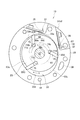
- FIG. 1 is a cross-sectional view showing an overall configuration of a vane rotary type gas compressor according to a first embodiment of the present invention.
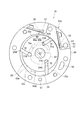
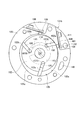
- 2 is a cross-sectional view taken along line II of the gas compressor of FIG. 3 is a cross-sectional view taken along the line II-II of the gas compressor of FIG.
- FIG. 4 is an explanatory diagram showing an enlarged main part of the compressed block shown in FIG.
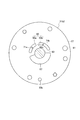
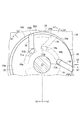
- FIG. 5 is an explanatory diagram showing a virtual example when the first supply unit and the second supply unit of the high-pressure supply groove of FIG. 3 are arranged apart from each other so that the back pressure space of the vane groove does not communicate with either. is there.
- FIG. 1 is a cross-sectional view showing an overall configuration of a vane rotary type gas compressor according to a first embodiment of the present invention.
- 2 is a cross-sectional view taken along line II of the gas compressor of FIG. 3 is a cross-sectional view taken along the line II-II of the gas compressor of FIG
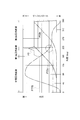
- FIG. 6 is a graph showing changes in the pressure in the compression chamber and the pressure in the back pressure space of the vane in the vane groove according to the rotation angle of the rotor in FIG.
- FIG. 7 is an explanatory diagram illustrating a communication cross-sectional area between the first supply portion, the second supply portion, and the back pressure space of the vane groove of the high pressure supply groove of FIG. 3.
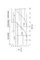
- FIG. 8 is a graph showing changes in the pressure in the compression chamber and the pressure in the back pressure space of the vane groove according to the rotation angle of the rotor in FIG. 3.
- FIG. 9 is a cross-sectional view of a vane rotary type gas compressor according to the second embodiment of the present invention at a position corresponding to the cross-sectional view of FIG. FIG.
- FIG. 10 is a cross-sectional view of a vane rotary type gas compressor according to the second embodiment of the present invention at a position corresponding to the cross-sectional view of FIG.
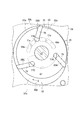
- FIG. 11 is an explanatory diagram showing an enlarged main part of the compressed block shown in FIG.
- FIG. 12 is an explanatory diagram showing a positional relationship between a region where the protruding stroke of the vane with respect to the vane groove decreases at a certain rate or more and a distance between the first supply unit and the second supply unit in the compression block shown in FIG. It is.
- FIG. 13 is a graph showing changes in the pressure in the compression chamber and the pressure in the back pressure space of the vane groove according to the rotation angle of the rotor in FIG. 12.
- FIG. 14 shows an interval between the region, the first supply unit, and the second supply unit in a period in which the vane slides in a region where the protruding stroke of the vane with respect to the vane groove decreases at a certain rate or more in the compression block shown in FIG.
- FIG. 15 is a graph showing changes in the pressure in the compression chamber and the pressure in the back pressure space of the vane groove according to the rotation angle of the rotor in FIG. 10.
- FIG. 16 is an explanatory view showing the inside of a compression block of a conventional gas compressor.
- FIG. 17 is a graph showing changes in the pressure in the compression chamber and the pressure in the back pressure space of the vane groove according to the rotation angle of the rotor in FIG. 16.
- a gas compressor 1 As shown in FIG. 1, a gas compressor 1 according to this embodiment includes a substantially cylindrical housing 2, a compression unit 3 accommodated in the housing 2, and a motor unit 4 that transmits a driving force to the compression unit 3. And an inverter unit 5 that is fixed to the housing 2 and controls the driving of the motor unit 4.
- the housing 2 includes a front head 7 in which a suction port (not shown) is formed and a bottomed cylindrical rear case 9 whose opening is closed by the front head 7.
- the compression part 3 is fixed to the inner wall 13 of the rear case 9.
- a suction chamber 11 is formed on one side of the compression unit 3 so as to partition the inside of the housing 2, and a discharge chamber 15 is formed on the other side.
- a discharge port (not shown) that connects the discharge chamber 15 and the refrigeration cycle is formed on the outer periphery of the rear case 9.
- an oil reservoir 17 in which oil O for maintaining the lubricity of the compression unit 3 is stored is formed below the discharge chamber 15.
- the compression unit 3 protrudes and retracts from the compression block 19 forming the cylinder chamber 33, the oil separator 21 fixed to the compression block 19, the rotor 23 rotatably accommodated in the cylinder chamber 33, and the rotor 23.
- a vane 25 (see FIG. 3) that partitions the cylinder chamber 33 and a drive shaft 27 that is fixed integrally with the rotor 23 and transmits a driving force are provided.
- the compression block 19 includes a cylinder block 29, a pair of side blocks 31, and a cylinder chamber 33 formed on the inner periphery of the cylinder block 29.
- the cylinder block 29 has an elliptical cylinder chamber 33 distorted inside.
- the opening of the cylinder chamber 33 is closed by holding both ends of the cylinder block 29 by a pair of side blocks 31.
- the rotor 23 is arranged so that one location is in contact with the inner wall of the cylinder chamber 33, and is arranged with the position shifted from the center (center of gravity) of the cylinder chamber 33 as the rotation center.
- a vane groove 75 opened on the outer peripheral surface of the rotor 23 and a back pressure space 77 on the back side of the vane 25 are provided.
- the cylinder chamber 33 is partitioned into a plurality of rotation directions X of the rotor 23 by a plurality of vanes 25 that appear and disappear from a plurality of vane grooves 75 of the rotor 23. Thereby, a plurality of compression chambers 33a, 33b, 33c are formed between the inner peripheral surface 33d of the cylinder chamber 33 and the outer peripheral surface 23a of the rotor 23.
- the cylinder block 29 includes a suction hole 39 for sucking refrigerant into the cylinder chamber 33, a discharge hole 35 for discharging refrigerant compressed in the cylinder chamber 33, an on-off valve 37 for opening and closing the discharge hole 35, and a side block. And a cylinder-side oil supply passage 41 communicating with the 31 oil supply passages.
- the pair of side blocks 31 includes a front side block 31a and a rear side block 31b, and an oil separator 21 is fixed to the rear side block 31b.
- the front side block 31a communicates with the front side end face 43 that contacts the cylinder block 29, the suction hole 39, a suction hole (not shown) that sucks refrigerant from the suction chamber 11, and a front side that rotatably supports the drive shaft 27.
- a bearing 47 and a front side oil supply path 49 communicating with the cylinder side oil supply path 41 are provided.
- the front-side end face 43 is provided with a pressure supply groove, and the pressure supply groove supplies an intermediate pressure (intermediate pressure) higher than the sucked refrigerant and lower than the pressure of the discharged refrigerant to the back pressure space 77.
- Intermediate pressure supply groove 51 and high pressure supply groove 53 provided at a position facing high pressure supply groove 69 on the rear side block 31b side.
- the front side bearing 47 is formed with an annular front side annular groove 55 and is provided in communication with one end side of the front side oil supply passage 49.
- the other end side of the front side oil supply passage 49 is in communication with the cylinder side oil supply passage 41.
- the rear side block 31 b is configured to freely rotate the rear side end face 57 that contacts the cylinder block 29, the oil supply hole 59 that sucks oil O stored below the discharge chamber 15, and the drive shaft 27.
- a rear-side bearing 63 to be supported and a rear-side oil supply passage 59b communicating with the cylinder-side oil supply passage 41 are provided.
- the rear-side end surface 57 has a discharge hole 61 for discharging the refrigerant compressed in the cylinder chamber 33, and an intermediate pressure that is higher than the pressure (suction pressure) of the sucked refrigerant and lower than the pressure (discharge pressure) of the discharged refrigerant.
- An intermediate pressure supply groove 67 for supplying oil to the back pressure space 77 (corresponding to an intermediate pressure supply portion in claims) and high pressure oil that is the pressure of the discharged refrigerant (discharge pressure) are supplied to the back pressure space 77.
- a high-pressure supply groove 69 (corresponding to a high-pressure supply part in claims).
- the high-pressure supply groove 69 is divided into a first supply unit 69a (corresponding to the upstream supply unit) and a second supply unit 69b (corresponding to the downstream supply unit) that are independent from each other in the rotational direction X of the rotor 23. Yes.
- the first supply portion 69a and the second supply portion 69b have high-pressure supply passages 71a and 71b, respectively.
- One end side of each of the high-pressure supply passages 71a and 71b communicates with the rear-side annular groove 73.
- the end sides communicate with the first supply unit 69a and the second supply unit 69b, respectively.
- the high-pressure supply groove 53 of the front side block 31a facing the high-pressure supply groove 69 is also divided into two supply parts (not shown) similar to the first supply part 69a and the second supply part 69b.
- the back pressure space 77 (see FIGS. 3 and 4) formed in the rotor 23 communicates with the intermediate pressure supply grooves 51 and 67 in the first half position of compression, and high pressure in the second half position of compression, as the rotor 23 rotates. It communicates with the supply grooves 53 and 69.
- the compression chamber 33b moved from the suction process to the compression process by the rotation of the rotor 23, and the compression moved from the compression process to the discharge process located downstream of the compression chamber 33b in the rotation direction X of the rotor 23.
- the back pressure space 77B of the vane groove 75 of the vane 25B that partitions the chamber 33a ends communication with the intermediate pressure supply groove 67. Then, the back pressure space 77B communicates with the first supply unit 69a located on the upstream side in the rotation direction X of the rotor 23.
- the back pressure space 77A of the vane groove 75 of the vane 25A that precedes the downstream side of the vane 25B in the rotation direction X of the rotor 23 has already finished communicating with the first supply unit 69a, and is downstream in the rotation direction X. It communicates with the second supply part 69b located on the side.
- the back pressure space 77A of the preceding vane 25A and the back pressure space 77B of the next vane 25B following the vane 25A do not communicate with the first supply unit 69a at the same time.
- the first supply unit 69a is formed. That is, in the rotation direction X of the rotor 23, the angle range in which the first supply unit 69a extends is smaller than the difference between the angle at which the back pressure space 77A is located and the angle at which the back pressure space 77B is located. ing. That is, the distance between the back pressure space 77A and the back pressure space 77B in the rotation direction X of the rotor 23 is set wider than the width of the first supply unit 69a.
- the back pressure space 77A of the preceding vane 25A and the back pressure space 77B of the next vane 25B following the vane 25A do not communicate with the second supply unit 69b at the same time.
- the second supply part 69b is formed in the shape. That is, in the rotation direction X of the rotor 23, the angle range in which the second supply portion 69b extends is smaller than the difference between the angle at which the back pressure space 77A is located and the angle at which the back pressure space 77B is located. ing. That is, the distance between the back pressure space 77A and the back pressure space 77B in the rotation direction X of the rotor 23 is set wider than the width of the second supply unit 69b.
- the angle range in which the first supply unit 69a extends and the second supply unit 69b extend As described above, based on the difference between the angle at which the back pressure space 77A is located and the angle at which the back pressure space 77B is located, the angle range in which the first supply unit 69a extends and the second supply unit 69b extend. Restrictions on the angle range to be generated occur.
- the angle range in which the first supply unit 69a extends and the second supply unit 69b extend are constraints on the angular range.
- the angle range in which the first supply unit 69a extends and the second supply unit 69b extend are constraints on the angular range.
- the shapes of the first supply unit 69a and the second supply unit 69b are determined based on the angle at which the back pressure space 77 is positioned in the rotation direction X of the rotor 23.
- the distance between the intermediate pressure supply groove 67 and the first supply portion 69a in the rotational direction X of the rotor 23 and the distance between the second supply portion 69b and the intermediate pressure supply groove 67 are the back in the rotational direction X of the rotor 23. It is set wider than the width of the pressure space 77.
- the oil supply hole 59 is formed in communication with the rear side oil supply path 59a, and is branched from the rear side oil supply path 59a to form a rear side oil supply path 59b.
- the rear side oil supply path 59 b communicates with the cylinder side oil supply path 41.
- the rear side bearing 63 is formed with an annular rear side annular groove 73 and communicates with the rear side communication path 65.
- the rear side communication passage 65 has one end communicating with the rear annular groove 73 and the other end opening into the high pressure supply groove 69.
- the oil separator 21 is fixed to the rear side block 31b, and the refrigerant compressed in the cylinder chamber 33 flows into the oil separator 21 to separate the refrigerant and the oil O from each other.
- the drive shaft 27 is fixed to the rotor 23 on one side and is rotatably supported by bearings 47 and 63 of the side blocks 31a and 31b.
- the motor unit 4 is fixed to the other side of the drive shaft 27.
- the motor unit 4 includes a stator 79 fixed to the inner wall 13 of the rear case 9 and a motor rotor 81 that is rotatably arranged on the inner peripheral side of the stator 79 and rotates by magnetic force.
- the motor rotor 81 is rotated by the magnetic force, so that the rotational driving force is transmitted to the compression unit 3.
- the distance between the first supply unit 69 a and the second supply unit 69 b in the rotation direction X of the rotor 23 is the distance of the back pressure space 77 in the rotation direction X of the rotor 23. It is set narrower than the width.
- FIG. 5 is an explanatory diagram showing a virtual example when the first supply unit and the second supply unit of the high-pressure supply groove of FIG. 3 are arranged apart from each other so that the back pressure space of the vane groove does not communicate with either. is there.
- FIG. 6 is a graph showing changes in the pressure P33a of the compression chamber 33a, the pressure P33b of the compression chamber 33b, and the back pressure space 77B according to the rotation angle of the rotor.
- the high-pressure supply groove 69 includes a first supply part 69a and a second supply part 69b, and the back pressure space 77B is formed by the first supply part as the rotor 23 rotates in the rotation direction X. After communicating with 69a, it communicates with the second supply unit 69b.
- the communication destination of the back pressure space 77B is the first.
- the vane 25B accommodated in the vane groove 75 where the back pressure space 77B is located between the first supply unit 69a and the second supply unit 69b is compressed by the compression chambers 33a and 33b partitioned by the vane 25B. Since the discharge process is performed from the latter stage, a force in the direction of immersing in the vane groove 75 is received from the inner peripheral surface 33 d of the cylinder chamber 33. That is, when the back pressure space 77B is located between the first supply part 69a and the second supply part 69b, the volume of the back pressure space 77B is decreasing.
- the back pressure space 77B since the back pressure space 77B is not in communication with either the first supply unit 69a or the second supply unit 69b at this position, the reduced pressure of the back pressure space 77B is high except for the back pressure space 77B. It cannot be evacuated anywhere. For this reason, as shown in P1 of FIG. 6, the pressure in the back pressure space 77 temporarily increases in the middle of the transition of the communication destination of the back pressure space 77B from the first supply unit 69a to the second supply unit 69b. To do. That is, since the back pressure space 77B does not communicate with either the first supply unit 69a or the second supply unit 69b, the pressure in the back pressure space 77 is temporarily increased as shown in P1 of FIG. To rise.
- a similar phenomenon may occur in a state where the vane 25A and the vane 25C are not in communication with either the first supply unit 69a or the second supply unit 69b.
- the back pressure space 77 communicates with the first supply unit 69a and the second supply unit 69b, the high-pressure supply that supplies high-pressure oil O to the first supply unit 69a and the second supply unit 69b.
- the high pressure in the back pressure space 77 can be retracted to the passages 71a, 71b, the rear side communication passage 65, the rear side annular groove 73, the rear side oil supply passage 59a, and the oil supply hole 59.
- the total of the above-described communication cross-sectional areas S1 and S3 reaches the oil supply hole 59 from the high-pressure supply passages 71a and 71b.
- the first supply unit 69a and the second supply unit 69b are spaced apart in the rotation direction X of the rotor 23 by an interval that is equal to or larger than the minimum passage cross-sectional area in the supply path of high-pressure oil O to the first supply unit 69a and the second supply unit 69b. Between the two.
- a current flows through a coil wound around the stator 79 of the motor unit 4 by the control of the inverter unit 5 shown in FIG.
- a current flows through the coil, a magnetic force is generated, and the motor rotor 81 disposed on the inner periphery of the stator 79 rotates.
- the refrigerant flows into the suction chamber 11, and the refrigerant is sucked from the suction chamber 11 into the cylinder chamber 33 through a suction hole (not shown) of the front side block 31a (suction process).
- the refrigerant sucked into the cylinder chamber 33 forms compression chambers 33a, 33b, 33c in the cylinder chamber 33 by the plurality of vanes 25, and the rotor 23 rotates to compress the refrigerant in the compression chambers 33a, 33b, 33c. (Compression process).
- the refrigerant compressed in the cylinder chamber 33 pushes the open / close valve 37 to discharge from the discharge hole 35 (discharge process), and is discharged from the discharge hole 61 to the discharge chamber 15 through the oil separator 21.
- the refrigerant discharged from the discharge hole 61 is separated into refrigerant and oil O by the oil separator 21, and the refrigerant is discharged from a discharge port (not shown) to a refrigeration cycle (not shown). It is stored in.
- the oil stored below the discharge chamber 15 is supplied from the oil supply hole 59 of the rear side block 31b to the rear side bearing 63 through the rear side oil supply path 59a.
- the high-pressure oil supplied to the rear-side bearing 63 is squeezed between the drive shaft 27 and thereby is higher than the pressure (suction pressure) of the sucked refrigerant and lower than the pressure (discharge pressure) of the discharged refrigerant.
- the oil O that has become the intermediate pressure is supplied to the intermediate pressure supply groove 67 through the gap between the drive shaft 27 and the rear side block 31b.
- the intermediate pressure oil O supplied to the intermediate pressure supply groove 67 supplies intermediate pressure to the back pressure space 77 from the refrigerant suction process to the compression process range, and the vane groove 75 supplies the vane.
- Intermediate pressure is supplied to the back surface of the vane 25 so that 25 protrudes.
- the high-pressure oil O supplied to the rear-side bearing 63 passes through the first supply portion 69a and the first supply portion 69a of the high-pressure supply groove 69 from the high-pressure supply passages 71a and 71b that open to the rear-side end surface 57 via the rear-side communication passage 65. 2 is supplied to the supply unit 69b.
- the high-pressure oil O supplied to the first supply unit 69a and the second supply unit 69b supplies high pressure to the back pressure space 77 from the refrigerant compression process to the discharge process as shown in FIG.
- High pressure is supplied to the back surface of the vane 25 so that the vane 25 protrudes from the groove 75.
- the first supply unit 69 a and the second supply unit 69 b communicate with the corresponding supply units (not shown) of the high pressure supply groove 53 on the front side block 31 a side via the back pressure space 77, and the high pressure supply groove 53.
- High pressure is also supplied from each supply section to the back pressure space 77.
- the high-pressure oil O flows from the oil supply hole 59 into the rear side oil supply path 59a, branches from the rear side oil supply path 59a, passes through the rear side oil supply path 59b, and passes through the cylinder side oil supply path 41. Then, the oil is supplied from the front oil supply passage 49 to the front bearing 47.
- the high pressure oil O supplied to the front side bearing 47 becomes an intermediate pressure by being squeezed between the drive shaft 27, and the oil O which has become the intermediate pressure is a gap between the drive shaft 27 and the front side block 31a. And is supplied to the intermediate pressure supply groove 51.
- the high-pressure oil O supplied from the high-pressure supply grooves 53 and 69 of the front side block 31a and the rear side block 31b is supplied to the back pressure space 77 of the rotor 23 at the second half rotation position of the rotor 23, and passes through the vane 25 from the vane groove 75.
- the back pressure to make it protrude is given.
- the back pressure space 77 of the vane groove 75 that has finished communicating with the intermediate pressure supply groove 67 communicates with the first supply part 69a of the high pressure supply groove 69, and the first supply part High pressure is supplied from 69a.
- the back pressure space 77 communicates with the first supply unit 69a before the back pressure space 77 of the next vane groove 75 located on the upstream side in the rotation direction X communicates with the first supply unit 69a.
- the back pressure space communicates with the second supply unit 69b located on the downstream side in the rotation direction X independent of the first supply unit 69a, and the high pressure is supplied again.
- the back pressure space 77 that has finished communicating with the intermediate pressure supply groove 67 communicates with the first supply portion 69 a of the high pressure supply groove 69, the back pressure space 77 is adjacent to the downstream side in the rotation direction X.
- the preceding back pressure space 77 does not communicate with the first supply unit 69a at the same time.
- the back pressure space 77A communicates with the first supply unit 69a before the back pressure space 77B of the next vane groove 75 located on the upstream side in the rotation direction X communicates with the first supply unit 69a. Is shown, and the high pressure is again supplied to the back pressure space 77A in communication with the second supply unit 69b located on the downstream side in the rotation direction X independent of the first supply unit 69a. ing.
- the back pressure space 77B communicates with the first supply portion 69a of the high pressure supply groove 69, the preceding back pressure space 77A adjacent to the downstream side in the rotation direction X of the back pressure space 77B is the first supply. There is no simultaneous communication with the portion 69a.
- a similar relationship is established not only between the back pressure space 77A and the back pressure space 77B, but also between the back pressure space 77B and the back pressure space 77C, and between the back pressure space 77C and the back pressure space 77A.
- the pressure in the preceding back pressure space 77 is temporarily increased by the intermediate pressure before the pressure increases to the high pressure in the following back pressure space 77 that follows. Can be prevented from being lowered from high pressure. Thereby, it is possible to prevent the occurrence of chattering in which the vane 25 repeatedly contacts and separates from the inner peripheral surface 33d of the cylinder chamber 33 due to temporary pressure reduction of the back pressure space 77 of the vane 25 in the first half of the compression process.
- the back pressure space 77 ends the communication with the second supply unit 69b before the back pressure space 77 of the next vane groove 75 located on the upstream side in the rotation direction X communicates with the second supply unit 69b. . Therefore, when the back pressure space 77 that has finished communicating with the first supply portion 69 a of the high pressure supply groove 69 communicates with the second supply portion 69 b of the high pressure supply groove 69, the back pressure space 77 in the rotational direction X The preceding back pressure space 77 adjacent to the downstream side does not communicate with the second supply unit 69b at the same time.
- FIG. 8 is a graph showing changes in the pressure P33a of the compression chamber 33a, the pressure P33b of the compression chamber 33b, and the back pressure space 77B according to the rotation angle of the rotor.
- the high-pressure supply groove 69 includes a first supply part 69a and a second supply part 69b, and the back pressure space 77B is formed by the first supply part as the rotor 23 rotates in the rotation direction X. After communicating with 69a, it communicates with the second supply unit 69b.
- the back pressure space 77 and the first supply unit 69a when the communication destination of the back pressure space 77 moves from the first supply unit 69a to the second supply unit 69b
- the total of the communication cross-sectional areas S1 and S3 with the second supply unit 69b is equal to or larger than the minimum passage cross-sectional area in the high-pressure oil O supply path to the first supply unit 69a and the second supply unit 69b.
- the back pressure space 77 is connected to at least one of the first supply part 69a or the second supply part 69b and the minimum passage.
- the second supply portion 69b of the high-pressure supply groove 69 has a shape as large as possible in the rotational direction X as long as two back pressure spaces 77 adjacent to each other in the rotational direction X of the rotor 23 do not communicate with each other. It is desirable. By doing so, the back pressure space 77 in which the pressure is increased from the intermediate pressure toward the high pressure by communication with the first supply unit 69a is changed from the early stage of the compression process of the compression chambers 33a, 33b, 33c to the second supply unit. 69 b and then the pressure in the back pressure space 77 can be stabilized at a high pressure.
- the discharge process of the compression chambers 33a, 33b, and 33c can be started at an early stage, and the on-off valve 37 of the discharge hole 35 is opened at an early stage, so that the high-pressure refrigerant in the compression chambers 33a, 33b, and 33c. Can be efficiently and sufficiently discharged, and the refrigerant compression efficiency can be improved.
- the high-pressure supply groove 69 is divided into two mutually independent first supply part 69a and second supply part 69b in the rotation direction X.
- the present invention is also applicable when the high-pressure supply groove 69 is divided into three or more supply parts in the rotation direction X. In that case, when the back pressure space 77 moves across the two supply parts adjacent in the rotation direction X, the upstream supply part and the communication cross-sectional area of the downstream supply part and the back pressure space 77 are The relationship of the invention will apply.
- FIGS. 9 and 10 show the structure of the vane rotary type gas compressor according to the second embodiment.
- the second embodiment has a rear side block 31b2 that is different from the rear side block 31b of the first embodiment.
- the configuration other than the rear side block 31b2 is the same as that of the first embodiment.
- the same components as those in the first embodiment are denoted by the same reference numerals in the drawings, and the description thereof is omitted.
- a gap 69c having a dimension equal to or larger than the back pressure space 77 of the vane groove 75 is provided between the first supply part 69a and the second supply part 69b. That is, the interval 69 c provided in the first supply unit 69 a and the second supply unit 69 b is set wider than the width of the back pressure space 77 of the vane groove 75.
- the compression chamber 33b moved from the suction process to the compression process by the rotation of the rotor 23, and the compression positioned downstream from the compression chamber 33b in the rotation direction X of the rotor 23 and moved from the compression process to the discharge process.
- a back pressure space 77B of the vane groove 75 of the vane 25B partitioning the chamber 33a communicates with the first supply portion 69a of the high pressure supply groove 69.
- the back pressure space 77B ends communication with the first supply unit 69a, and the back pressure space 77B is connected to the first supply unit 69a and the second supply unit 69a. It communicates with an interval 69c provided between the supply parts 69b. At this time, the back pressure space 77B does not communicate with either the first supply unit 69a or the second supply unit 69b.
- the region shown in the range of FIG. 12A on the inner peripheral surface 33d of the cylinder chamber 33 that is, the rate at which the protrusion stroke of the vane 25B with respect to the vane groove 75 with a rotation in the rotation direction X of the rotor 23 is a certain level or more It is assumed that when the vane 25B is in sliding contact with the area that decreases in step, a space 69c is disposed at a position where the back pressure space 77B communicates.
- FIG. 12 is an explanatory diagram showing a positional relationship between a region where the projecting stroke of the vane 25B with respect to the vane groove 75 decreases at a certain rate or more and the interval 69c.
- the volume of the back pressure space 77B decreases at a rate corresponding to the reduction rate of the protruding stroke of the vane 25B in a state where the back pressure space 77B is blocked from the first supply unit 69a and the second supply unit 69b. As shown at P1 in FIG. 13, the pressure in the back pressure space 77B temporarily rises.
- a predetermined threshold value at which the reduction rate of the protruding stroke of the vane 25 with respect to the vane groove 75 due to the rotation of the rotor 23 in the rotation direction X on the inner peripheral surface 33d of the cylinder chamber 33 is lower than the above-described constant rate.
- the region having the following reduction rate is a region where the reduction rate of the protruding stroke is small.
- the inner peripheral surface 33d of the cylinder chamber 33 is as shown in FIG. (A) a region in which the protruding stroke from the vane groove 75 of the vane 25 slidably contacting the inner peripheral surface 33d of the cylinder chamber 33 increases as the rotor 23 rotates in the rotation direction X; (B) a region in which the protrusion stroke from the vane groove 75 of the vane 25 slidably contacting the inner peripheral surface 33d of the cylinder chamber 33 decreases as the rotor 23 rotates in the rotation direction X; (C) The protrusion stroke from the vane groove 75 of the vane 25 slidably in contact with the inner peripheral surface 33d of the cylinder chamber 33 decreases with the rotation of the rotor 23 in the rotation direction X, and the rate of decrease is the region (b).
- the back pressure space 77 is spaced at a position where it communicates. 69c is arranged.
- the back pressure space 77 that has finished communicating with the intermediate pressure supply groove 67 communicates with the first supply portion 69 a of the high pressure supply groove 69
- the back pressure space 77 is downstream in the rotational direction X.
- the preceding back pressure space 77 adjacent to the first supply portion 69a does not communicate with the first supply portion 69a at the same time.
- the back pressure space 77 that has finished communicating with the intermediate pressure supply groove 67 communicates with the first supply portion 69 a of the high pressure supply groove 69, the back pressure space 77 is adjacent to the downstream side in the rotation direction X.
- the preceding back pressure space 77 does not communicate with the first supply unit 69a at the same time.
- the pressure in the preceding back pressure space 77 is temporarily increased by the intermediate pressure before the pressure increases to the high pressure in the following back pressure space 77 that follows. Can be prevented from being lowered from high pressure. Thereby, it is possible to prevent the occurrence of chattering in which the vane 25 repeatedly contacts and separates from the inner peripheral surface 33d of the cylinder chamber 33 due to temporary pressure reduction of the back pressure space 77 of the vane 25 in the first half of the compression process.
- the back pressure space 77 ends the communication with the second supply unit 69b before the back pressure space 77 of the next vane groove 75 located on the upstream side in the rotation direction X communicates with the second supply unit 69b. . Therefore, when the back pressure space 77 that has finished communicating with the first supply portion 69 a of the high pressure supply groove 69 communicates with the second supply portion 69 b of the high pressure supply groove 69, the back pressure space 77 in the rotational direction X The preceding back pressure space 77 adjacent to the downstream side does not communicate with the second supply unit 69b at the same time.
- the vane 25 repeatedly contacts and separates from the inner peripheral surface 33 d of the cylinder chamber 33 due to the temporary pressure reduction of the back pressure space 77 of the vane 25 in the later stage of the compression process or the discharge process. Generation of chattering can be prevented.
- the back pressure space 77 when the back pressure space 77 communicates with the gap 69c between the first supply portion 69a and the second supply portion 69b, the back pressure space 77 has a vane groove 75.
- the first supply unit 69a and the second supply unit are arranged so that the accommodated vane 25 is in sliding contact with the region (c) in which the reduction rate of the protruding stroke of the vane 25 accompanying the rotation of the rotor 23 in the rotation direction X is the lowest.
- An interval 69c with respect to 69b is located.
- the second supply portion 69b of the high-pressure supply groove 69 has a shape as large as possible in the rotational direction X as long as two back pressure spaces 77 adjacent to each other in the rotational direction X of the rotor 23 do not communicate with each other. It is desirable. By doing so, the back pressure space 77 in which the pressure is increased from the intermediate pressure toward the high pressure by communication with the first supply unit 69a is changed from the early stage of the compression process of the compression chambers 33a, 33b, 33c to the second supply unit. 69 b and then the pressure in the back pressure space 77 can be stabilized at a high pressure.
- the discharge process of the compression chambers 33a, 33b, and 33c can be started at an early stage, and the on-off valve 37 of the discharge hole 35 is opened at an early stage, so that the high-pressure refrigerant in the compression chambers 33a, 33b, and 33c. Can be efficiently and sufficiently discharged, and the refrigerant compression efficiency can be improved.
- the interval 69c provided in the first supply unit 69a and the second supply unit 69b is set to be wider than the width of the back pressure space 77 of the vane groove 75. May be smaller than the back pressure space 77 in the rotational direction X of the rotor 23.
- the back pressure space 77 straddles the interval 69c when the communication destination of the back pressure space 77 shifts from the first supply unit 69a of the high pressure supply unit 69 to the second supply unit 69b, it overlaps with the interval 69c.
- the communication cross-sectional area with respect to each supply part 69a, 69b of the back pressure space 77 decreases.
- the back pressure space 77 is reduced by the reduced volume.
- the efficiency of evacuating the internal high pressure to the first supply unit 69a and the second supply unit 69b decreases.
- the pressure in the back pressure space 77 temporarily rises in the later stage of the compression process and in the discharge process, and the force with which the vane 25 presses the inner peripheral surface 33d of the cylinder chamber 33 increases more than necessary, and the vane 25 and the cylinder chamber are increased.
- the sliding resistance with the inner peripheral surface 33d of 33 may increase.
- the area of the inner peripheral surface 33d of the cylinder chamber 33 that the vane 25 is in sliding contact with when the back pressure space 77 communicates with the interval 69c is used as a guideline for the reduction rate of the protruding stroke of the vane 25 relative to the vane groove 75 Decided.
- the upper limit value of the allowable range of the reduction rate of the protruding stroke of the vane 25 with respect to the vane groove 75 is determined according to the allowable range for the temporary increase of the pressure in the back pressure space 77.
- a region on the inner peripheral surface 33d of the cylinder chamber 33 is determined such that the reduction rate of the protruding stroke of the vane 25 is equal to or less than this threshold value. What is necessary is just to arrange
- the back pressure space 77 is reduced due to a decrease in the protruding stroke of the vane 25 during the period in which the back pressure space 77 communicates with the gap 69c between the first supply portion 69a and the second supply portion 69b.
- Temporary pressure increase can be within an allowable range. Therefore, the sliding resistance of the vane 25 with respect to the inner peripheral surface 33d of the cylinder chamber 33 increases due to the temporary pressure increase in the back pressure space 77 in the later stage of the compression process or in the discharge process, and the power necessary for the rotation of the rotor 23 increases. And the operation performance as the gas compressor 1 can be maintained.
- the high-pressure supply groove 69 is divided into two mutually independent first supply part 69a and second supply part 69b in the rotation direction X.
- the present invention is also applicable when the high-pressure supply groove 69 is divided into three or more supply parts in the rotation direction X. In that case, the relationship of the present invention is applied to the relative position between the interval between two supply parts adjacent in the rotation direction X and the inner peripheral surface of the cylinder chamber.
- the second supply portion 69 b of the high-pressure supply groove 69 has a size that prevents the two back pressure spaces 77 adjacent in the rotation direction X of the rotor 23 from communicating simultaneously.
- the second supply unit 69b may have a larger dimension than the first supply unit 69a.
- the discharge process of the compression chambers 33a, 33b, and 33c can be started at an early stage, and the on-off valve 37 of the discharge hole 35 is opened at an early stage, so that the high-pressure refrigerant in the compression chambers 33a, 33b, and 33c. Can be efficiently and sufficiently discharged, and the refrigerant compression efficiency can be improved.
- the high pressure supply groove 69 is rotated in the rotational direction X.
- the first supply unit 69a and the second supply unit 69b are divided into two parts.
- the present invention is also widely applicable when the high-pressure supply groove 69 is divided into three or more supply parts in the rotation direction X.
- the two back parts adjacent to each other in the rotation direction X of the supply part communicating with the back pressure space 77 in a state where the pressure of the back pressure space 77 rises from the intermediate pressure to the high pressure. If the pressure spaces 77 are formed so as not to communicate with each other at the same time, the same effects as those of the above-described embodiments can be obtained.
- the supply portion located second from the most upstream side in the rotation direction X is an object to be formed in a shape in which at least two adjacent back pressure spaces 77 in the rotation direction X do not communicate with each other at the same time.
- the third and subsequent supply units from the most upstream side also communicate with the back pressure space 77 when the pressure in the back pressure space 77 is increasing from the intermediate pressure to the high pressure.
- the pressure space 77 serves as a target supply unit formed into a shape that does not communicate with each other at the same time.
- the back pressure space of the vane groove that has finished communicating with the intermediate pressure supply unit is supplied with high pressure until the refrigerant pressure in the compression chamber partitioned by the vane housed in the vane groove reaches the maximum pressure.
- High pressure is supplied from the first supply unit in communication with the first supply unit. After that, the back pressure space is communicated with the first supply unit before the back pressure space of the next vane groove on the upstream side in the rotation direction communicates with the first supply unit.
- the high pressure is supplied again by communicating with the next independent second supply section.
- the preceding back pressure space adjacent to the downstream side in the rotational direction of the back pressure space is , It does not communicate with the first supply unit at the same time. Therefore, the pressure in the preceding back pressure space is temporarily prevented from being lowered from the high pressure by the intermediate pressure in the following back pressure space, and the chattering of the vane due to the temporary pressure reduction in the vane back pressure space is prevented. can do.
Landscapes
- Engineering & Computer Science (AREA)
- Mechanical Engineering (AREA)
- General Engineering & Computer Science (AREA)
- Rotary Pumps (AREA)
- Applications Or Details Of Rotary Compressors (AREA)
Abstract
中間圧供給溝(67)との連通を終えたベーン溝(75)の背圧空間(77)が、そのベーン溝(75)のベーン(25)で仕切られた圧縮室(33a,33b,33c)の冷媒圧力が最高圧に達するまで、第1供給部(69a)に連通し第1供給部(69a)から高圧が供給される。中間圧供給溝(67)との連通を終えた背圧空間(77)が高圧供給溝(69)の第1供給部(69a)に連通する時点で、その背圧空間(77)の回転方向Xにおける下流側に隣り合う先行の背圧空間(77)は、第1供給部(69a)との連通を終える。
Description
本発明は、いわゆるベーンロータリー型の気体圧縮機に関する。
特許文献1に示すように、従来、種々の気体圧縮機が提案されている。
図16は、特許文献1に関連する気体圧縮機の内部に配置される圧縮ブロックを示している。
この圧縮ブロックは、シリンダブロック100と、シリンダブロック100の左右に配置される一対のサイドブロック101とを有する。シリンダブロック100と一対のサイドブロック101の内部には、シリンダ室105が形成されている。シリンダブロック100には、吸入口110と2つの吐出口108が設けられている。
シリンダ室105には、ロータ102が回転自在に配置されている。ロータ102には、間隔を置いて複数のベーン溝106が形成されている。各ベーン溝106には、ロータ102の外周面より出没自在にベーン103が配置されている。ベーン溝106のベーン103より背面側には、背圧空間107(107A、107B、107C)が形成されている。背圧空間107は、ロータ102の両側面に開口している。
各サイドブロック101のシリンダ室105側の壁面には、背圧空間107の回転軌跡上に中間圧供給溝113と高圧供給溝114が形成されている。中間圧供給溝113には、吸入した冷媒よりも高く、吐出した冷媒よりも低い圧力である中間圧が供給される。高圧供給溝114には、吐出した冷媒と同等の圧力である高圧が供給される。
シリンダ室105には、2つのベーン103に囲まれて圧縮室105a,105b,105cが形成される。ロータ102の回転時には、圧縮室105a,105b,105cは、吸入工程と圧縮工程と吐出工程を行い、この一連の工程を繰り返す。
吸入工程では、圧縮室105a,105b,105cの容積が徐々に大きくなって吸入口110より冷媒を吸入する。圧縮工程では、圧縮室105a,105b,105cの容積が徐々に小さくなって冷媒を圧縮する。吐出工程では、圧縮室105a,105b,105cの容積が徐々に小さくなるとともに冷媒圧が所定圧以上になると、開閉弁109が開いて冷媒を吐出口108より吐出する。
このような一連の工程において、各ベーン103には、圧縮室105a,105b,105cの冷媒圧力が各ベーン103をベーン溝106へ収納する方向(以下「収納方向」)に押圧するが、背圧空間107に作用する背圧によって各ベーン103の先端がシリンダ室105の内壁を摺動し、圧縮室105a,105b,105cが冷媒を確実に圧縮することができるようになっている。
ここで、収納方向の圧力が小さい吸入工程や圧縮工程の初期では、中間圧供給溝113からの中間圧を背圧として作用させる。また、ベーン103の収納方向への圧力が大きい圧縮工程の後期や吐出工程では、高圧供給溝114からの高圧を背圧として作用させる。このように、ベーン103に作用させる背圧をベーン103の収納方向への圧力に応じて変更することによって、ベーン103の摺動抵抗を極力小さくし低燃費化を図っている。
図17は、圧縮室105aの圧力P105a、圧縮室105bの圧力P105b、及び、背圧空間107Aの圧力P107Aの、ロータの回転角度に応じた変化を示すグラフである。図17に示されているように、角度180度のときに、中間圧供給溝113との連通を終了した背圧空間107Aが高圧供給溝114に連通する。
図16に示す例では、背圧空間107Bが中間圧供給溝113から高圧供給溝114に連通状態を移行する際に、先行する回転下流の背圧空間107Aが高圧供給溝114に既に連通している。このため、追従する回転上流の背圧空間107Bが高圧供給溝114への連通状態に移行し終えると、2つの背圧空間107A,107Bが同時に高圧供給溝114に連通する状態となる。
回転上流の背圧空間107Bの圧力P107Bが中間圧であるため、回転上流の背圧空間107Bと高圧供給溝114を介して連通する回転下流の背圧空間107Aの圧力P107Aが、図17のPに示すように、高圧供給溝114に供給される圧力よりも一時的に低下する。回転下流側のベーン103には、圧縮工程の後期や吐出工程の圧縮室105a,105b,105cの冷媒の圧力がベーン103の収納方向に作用しているため、ベーン103がベーン溝106に一時的に収納されてチャタリングが発生する可能性がある。
本発明は前記事情に鑑みなされたもので、本発明の目的は、例えば、圧縮工程の後期や吐出工程におけるベーンの背圧空間の一時的な減圧によるベーンのチャタリング発生を防止し、かつ、気体圧縮機としての動作性能を維持することにある。
上記目的を達成するため、本発明の気体圧縮機は、
冷媒が圧縮されるシリンダ室を内部に有する筒状のシリンダブロックと、
前記シリンダブロックの側部に取り付けられ、該側部における前記シリンダ室の開口を封止するサイドブロックと、
前記シリンダ室内で回転し、前記シリンダ室の内周面に対向する外周面に開口する複数のベーン溝を回転方向に間隔をおいて複数有するロータと、
前記各ベーン溝にそれぞれ収納されて前記外周面から出没し、前記シリンダ室の内周面に摺接して該内周面と前記ロータの外周面との間を複数の圧縮室に仕切る複数のベーンと、
前記サイドブロックの少なくとも一方に形成され、吸入工程から圧縮工程にかけての前記圧縮室を仕切る前記ベーンを収容した前記ベーン溝の溝底の背圧空間に連通して、吸入工程から圧縮工程にかけての前記圧縮室の冷媒圧力より大きい中間圧を前記背圧空間に供給する中間圧供給部と、
前記サイドブロックの少なくとも一方に形成され、圧縮工程から吐出工程にかけての前記圧縮室を仕切る前記ベーンを収容した前記ベーン溝の前記背圧空間に、前記中間圧供給部との連通を終えた後に連通して、圧縮工程から吐出工程にかけての前記圧縮室の冷媒圧力及び前記中間圧より大きい高圧を前記背圧空間に供給する高圧供給部とを備えており、
前記高圧供給部は、前記回転方向において複数の互いに独立した供給部に分割されており、
前記回転方向の最上流側から2番目に位置する第2供給部は、1つのベーン溝の前記背圧空間が連通している間、該ベーン溝と前記回転方向の上流側において隣り合う他の前記ベーン溝の前記背圧空間が同時に連通しない形状に形成されているとともに、前記高圧供給部は、1つの前記ベーン溝の前記背圧空間と、該ベーン溝と前記回転方向の上流側において隣り合う他の前記ベーン溝の前記背圧空間とが、同時に連通する範囲に形成されている。
[第1実施形態]
本発明の第1実施形態について図1~図8を参照しながら説明する。
本発明の第1実施形態について図1~図8を参照しながら説明する。
図1に示すように、本実施形態に係る気体圧縮機1は、略円筒状のハウジング2と、ハウジング2内に収容される圧縮部3と、圧縮部3に駆動力を伝達するモータ部4と、ハウジング2に固定され、モータ部4の駆動を制御するインバータ部5とを備えている。
ハウジング2は、図示しない吸入ポートが形成されるフロントヘッド7と、開口をフロントヘッド7に閉塞される有底筒状のリアケース9とからなっている。
リアケース9の内壁13には圧縮部3が固定されている。圧縮部3には、ハウジング2内を区画するようにして一方側に吸入室11が形成され、他方側に吐出室15が形成されている。また、リアケース9の外周には、吐出室15と冷凍サイクルとを連通する図示しない吐出ポートが形成されている。また、吐出室15の下方には、圧縮部3の潤滑性を保つための油Oが貯留する油溜まり17が形成されている。
圧縮部3は、シリンダ室33を形成する圧縮ブロック19と、圧縮ブロック19に固定される油分離器21と、シリンダ室33内に回転自在に収容されるロータ23と、ロータ23から出没してシリンダ室33を仕切るベーン25(図3参照)と、ロータ23と一体に固定されて駆動力を伝達する駆動軸27とを備えている。
圧縮ブロック19は、シリンダブロック29と、一対のサイドブロック31と、シリンダブロック29の内周に形成されるシリンダ室33とからなっている。
図3に示すようにシリンダブロック29は、内部に歪んだ楕円形状のシリンダ室33を有している。このシリンダ室33の開口は、シリンダブロック29の両端を一対のサイドブロック31によって狭持することにより閉塞される。
図3、図4に示すようにロータ23は、1箇所がシリンダ室33の内壁に接するように配置され、シリンダ室33の中心(重心)よりずれた位置を回転中心にして配置されており、ロータ23の外周面に開口するベーン溝75と、ベーン25の背面側の背圧空間77とを備えている。
シリンダ室33は、ロータ23の複数のベーン溝75から出没する複数のベーン25によって、ロータ23の回転方向Xに複数に仕切られる。これにより、シリンダ室33の内周面33dとロータ23の外周面23aとの間に複数の圧縮室33a,33b,33cが形成される。
また、シリンダブロック29は、シリンダ室33内に冷媒を吸入する吸入孔39と、シリンダ室33内で圧縮した冷媒を吐出する吐出孔35と、吐出孔35を開閉する開閉弁37と、サイドブロック31の油供給路と連通するシリンダ側油供給路41とを備えている。
図1に示すように、一対のサイドブロック31は、フロントサイドブロック31aとリアサイドブロック31bとからなっており、リアサイドブロック31bには油分離器21が固定されている。
フロントサイドブロック31aは、シリンダブロック29に当接するフロント側端面43と、吸入孔39と連通し、吸入室11から冷媒を吸入する図示しない吸入孔と、駆動軸27を回転自在に支持するフロント側軸受47と、シリンダ側油供給路41と連通するフロント側油供給路49とを備えている。
フロント側端面43には、圧力供給溝が設けられており、圧力供給溝は、吸入した冷媒よりも高く、吐出する冷媒の圧力よりも低い中間の圧力(中間圧)を背圧空間77へ供給する中間圧供給溝51と、リアサイドブロック31b側の高圧供給溝69に対向する位置に設けられる高圧供給溝53とを備えている。
また、フロント側軸受47には、環状のフロント側環状溝55が形成されており、フロント側油供給路49の一端側に連通して設けられている。なお、フロント側油供給路49の他端側は、シリンダ側油供給路41と連通している。
図2に示すように、リアサイドブロック31bは、シリンダブロック29に当接するリア側端面57と、吐出室15の下方に貯留する油Oを吸入する油供給穴59と、駆動軸27を回転自在に支持するリア側軸受63と、シリンダ側油供給路41と連通するリア側油供給路59bとを備えている。
リア側端面57は、シリンダ室33内で圧縮した冷媒を吐出する吐出穴61と、吸入した冷媒の圧力(吸入圧)よりも高く、吐出した冷媒の圧力(吐出圧)よりも低い中間圧の油を背圧空間77へ供給する中間圧供給溝67(請求項中の中間圧供給部に相当)と、吐出した冷媒の圧力(吐出圧)である高圧の油を背圧空間77へ供給する高圧供給溝69(請求項中の高圧供給部に相当)とを備えている。
高圧供給溝69は、ロータ23の回転方向Xにおいて、互いに独立した第1供給部69a(上流側の供給部に相当)及び第2供給部69b(下流側の供給部に相当)に分割されている。
また、第1供給部69a及び第2供給部69bには、高圧供給通路71a,71bがそれぞれ開口しており、各高圧供給通路71a,71bは、一端側がリア側環状溝73に連通し、他端側が第1供給部69a及び第2供給部69bにそれぞれ連通している。
なお、高圧供給溝69に対向するフロントサイドブロック31aの高圧供給溝53も、第1供給部69a及び第2供給部69bと同様の2つの供給部(図示せず)に分割されている。
ロータ23に形成された背圧空間77(図3、図4参照)は、ロータ23が回転することにより、圧縮前半位置では、中間圧供給溝51,67と連通し、圧縮後半位置では、高圧供給溝53,69と連通する。
図4に示す状態では、ロータ23の回転により吸入工程から圧縮工程にかけて移動した圧縮室33bと、ロータ23の回転方向Xにおける圧縮室33bの下流側に位置し圧縮工程から吐出工程にかけて移動した圧縮室33aとを仕切るベーン25Bのベーン溝75の背圧空間77Bが、中間圧供給溝67との連通を終えている。そして、背圧空間77Bは、ロータ23の回転方向Xにおける上流側に位置する第1供給部69aにこれから連通する。
この状態では、ロータ23の回転方向Xにおけるベーン25Bの下流側を先行するベーン25Aのベーン溝75の背圧空間77Aは、第1供給部69aとの連通を既に終えて、回転方向Xの下流側に位置する第2供給部69bと連通している。
そして、ロータ23の回転方向Xにおいて、先行するベーン25Aの背圧空間77Aとベーン25Aに追従する次のベーン25Bの背圧空間77Bとが、同時に第1供給部69aに連通することがない形状に、第1供給部69aは形成されている。すなわち、ロータ23の回転方向Xにおいて、背圧空間77Aが位置する角度と背圧空間77Bが位置する角度の差よりも、第1供給部69aの延在する角度範囲が小さくなるように形成されている。つまり、ロータ23の回転方向Xにおける背圧空間77Aと背圧空間77Bとの距離は、第1供給部69aの幅よりも幅広に設定されている。
同様に、ロータ23の回転方向Xにおいて、先行するベーン25Aの背圧空間77Aとベーン25Aに追従する次のベーン25Bの背圧空間77Bとが、同時に第2供給部69bに連通することがない形状に、第2供給部69bは形成されている。すなわち、ロータ23の回転方向Xにおいて、背圧空間77Aが位置する角度と背圧空間77Bが位置する角度の差よりも、第2供給部69bの延在する角度範囲が小さくなるように形成されている。つまり、ロータ23の回転方向Xにおける背圧空間77Aと背圧空間77Bとの距離は、第2供給部69bの幅よりも幅広に設定されている。
上述したように、背圧空間77Aが位置する角度と背圧空間77Bが位置する角度の差に基づいて、第1供給部69aが延在する角度範囲、及び、第2供給部69bが延在する角度範囲に対する制約が生じる。
同様にして、背圧空間77Bが位置する角度と背圧空間77Cが位置する角度の差に基づいて、第1供給部69aが延在する角度範囲、及び、第2供給部69bが延在する角度範囲に対する制約が生じる。
同様にして、背圧空間77Cが位置する角度と背圧空間77Aが位置する角度の差に基づいて、第1供給部69aが延在する角度範囲、及び、第2供給部69bが延在する角度範囲に対する制約が生じる。
このように、ロータ23の回転方向Xにおいて背圧空間77が位置する角度に基づいて、第1供給部69a及び第2供給部69bの形状が定められる。
なお、ロータ23の回転方向Xにおける中間圧供給溝67と第1供給部69aとの距離、及び、第2供給部69bと中間圧供給溝67との距離は、ロータ23の回転方向Xにおける背圧空間77の幅よりも幅広に設定されている。
図1に示すように、油供給穴59は、リア側油供給路59aと連通して形成されており、リア側油供給路59aから分岐してリア側油供給路59bが形成されている。このリア側油供給路59bは、シリンダ側油供給路41に連通している。
リア側軸受63には、環状のリア側環状溝73が形成されており、リア側連通路65と連通している。リア側連通路65は、一端側がリア側環状溝73と連通し、他端側が高圧供給溝69に開口している。
油分離器21は、リアサイドブロック31bに固定され、シリンダ室33内で圧縮された冷媒が油分離器21に流入し、冷媒と油Oとを分離させている。
駆動軸27は、一方側をロータ23に固定されるとともに、各サイドブロック31a,31bの軸受47,63によって回転自在に支持されている。また、駆動軸27の他方側には、モータ部4が固定されている。
モータ部4は、リアケース9の内壁13に固定されるステータ79と、ステータ79の内周側に回転自在に配置され、磁力によって回転するモータロータ81とを備えている。磁力によってモータロータ81が回転することで、圧縮部3へ回転駆動力を伝達している。
ここで、ロータ23の回転方向Xにおける高圧供給溝69の第1供給部69aと第2供給部69bとの間隔について説明する。
本実施形態では、図3、図4に示すように、ロータ23の回転方向Xにおける第1供給部69aと第2供給部69bとの距離は、ロータ23の回転方向Xにおける背圧空間77の幅よりも、狭く設定されている。
ここで、図5に示すように、ロータ23の回転方向Xにおける高圧供給溝69の第1供給部69aと第2供給部69bとの間隔が、背圧空間77の幅よりも幅広であると仮定する。図5は、図3の高圧供給溝の第1供給部と第2供給部とを、ベーン溝の背圧空間がどちらにも連通しない間隔に離して配置した場合の仮想例を示す説明図である。
図6は、圧縮室33aの圧力P33a、圧縮室33bの圧力P33b、及び、背圧空間77Bの、ロータの回転角度に応じた変化を示すグラフである。図6に示されているように、角度180度のときに、中間圧供給溝67との連通を終了した背圧空間77Bが高圧供給溝69に連通する。本実施形態では、高圧供給溝69は第1供給部69aと第2供給部69bから構成されており、回転方向Xで回転するロータ23の回転に伴い、背圧空間77Bは、第1供給部69aに連通した後に、第2供給部69bに連通する。
ロータ23の回転方向Xにおける高圧供給溝69の第1供給部69aと第2供給部69bとの間隔が、背圧空間77Bの幅よりも幅広であるため、背圧空間77Bの連通先が第1供給部69aから第2供給部69bに移行する際に、背圧空間77Bが第1供給部69aと第2供給部69bとのどちらとも連通していない状態が発生する。
このとき、第1供給部69aと第2供給部69bとの間に背圧空間77Bが位置するベーン溝75に収容されたベーン25Bは、ベーン25Bによって仕切られた圧縮室33a,33bが圧縮工程の後期から吐出工程にいることから、ベーン溝75に没入する方向の力をシリンダ室33の内周面33dから受けている。即ち、背圧空間77Bが第1供給部69aと第2供給部69bとの間に位置する時に、背圧空間77Bの体積は減少中の状況にある。
ところが、この位置では背圧空間77Bが第1供給部69aと第2供給部69bとのどちらとも連通していないので、背圧空間77Bの減少した体積分の高圧は、背圧空間77B以外のどこにも退避することができない。このため、背圧空間77Bの連通先が第1供給部69aから第2供給部69bに移行する途中の段階において、図6のP1に示すように、背圧空間77の圧力が一時的に上昇する。すなわち、背圧空間77Bが第1供給部69aと第2供給部69bとのどちらとも連通していない状態が生じるため、図6のP1に示すように、背圧空間77の圧力が一時的に上昇する。
このような背圧空間77Bの圧力上昇が生じると、シリンダ室33の内周面33dからベーン溝75に没入する方向の力を受けているベーン25Bが、上昇した背圧空間77Bの圧力でベーン溝75から突出しようとする。すると、シリンダ室33の内周面33dに対するベーン25Bの押し付け力が必要以上に増えて、ベーン25Bとシリンダ室33の内周面33dとの摺動抵抗が増大してしまう可能性がある。
同様の現象は、ベーン25Aやベーン25Cが、第1供給部69aと第2供給部69bとのどちらとも連通していない状態において生じうる。
そこで、本実施形態の気体圧縮機1では、図7に示すように、背圧空間77の連通先が第1供給部69aから第2供給部69bに移行するときに、背圧空間77と第1供給部69aとの連通断面積S1と、背圧空間77と第2供給部69bとの連通断面積S3とを合計した断面積を、一定以上確保するようにしている。
具体的には、背圧空間77が第1供給部69aや第2供給部69bに連通しているときは、第1供給部69aや第2供給部69bに高圧の油Oを供給する高圧供給通路71a,71bやそれに連なるリア側連通路65、リア側環状溝73、リア側油供給路59a及び油供給穴59に、背圧空間77の高圧を退避させることができる。
これと同等以上の高圧退避経路を確保するために、本実施形態の気体圧縮機1では、上述した連通断面積S1,S3の合計が、高圧供給通路71a,71bから油供給穴59に至る、第1供給部69aや第2供給部69bに対する高圧の油Oの供給経路における最小通路断面積以上となるような間隔を、ロータ23の回転方向Xにおいて第1供給部69aと第2供給部69bとの間に持たせている。
次に、本実施形態における気体圧縮機1の動作について説明する。
まず、図1に示すインバータ部5の制御によって、モータ部4のステータ79に巻き掛けられたコイルに電流が流れる。コイルに電流が流れることにより磁力が発生し、ステータ79の内周に配置されたモータロータ81が回転する。
モータロータ81が回転することにより、一端側にモータロータ81が固定された駆動軸27が回転し、他端側の駆動軸27に固定されたロータ23も回転する。
ロータ23の回転とともに、吸入室11に冷媒が流入し、吸入室11からフロントサイドブロック31aの吸入孔(不図示)を介してシリンダ室33へ冷媒が吸入される(吸入工程)。シリンダ室33へ吸入した冷媒は、複数のベーン25によってシリンダ室33内に圧縮室33a,33b,33cが形成され、ロータ23が回転することによって圧縮室33a,33b,33c内の冷媒を圧縮している(圧縮工程)。
シリンダ室33内で圧縮された冷媒は、開閉弁37を押し開けて吐出孔35から吐出し(吐出工程)、吐出穴61から油分離器21を介して吐出室15へ吐出される。また、吐出穴61から吐出した冷媒は、油分離器21によって冷媒と油Oとに分離され、冷媒は、図示しない吐出ポートから図示しない冷凍サイクルに吐出し、油Oは、吐出室15の下方に貯留される。
吐出室15の下方に貯留した油は、リアサイドブロック31bの油供給穴59からリア側油供給路59aを通りリア側軸受63へ供給される。
リア側軸受63へ供給された高圧の油は、駆動軸27との間で絞られることによって、吸入した冷媒の圧力(吸入圧)よりも高く、吐出した冷媒の圧力(吐出圧)よりも低い中間圧となり、中間圧となった油Oは駆動軸27とリアサイドブロック31bとの間の隙間を通って中間圧供給溝67へ供給される。
中間圧供給溝67へ供給された中間圧の油Oは、図3に示すように、冷媒の吸入工程から圧縮工程の範囲にかけて、背圧空間77に中間圧を供給し、ベーン溝75からベーン25が突出するようにベーン25の背面に中間圧を供給している。
また、リア側軸受63へ供給された高圧の油Oは、リア側連通路65を介してリア側端面57に開口する高圧供給通路71a,71bから高圧供給溝69の第1供給部69a及び第2供給部69bへ供給される。
第1供給部69a及び第2供給部69bへ供給された高圧の油Oは、図3に示すように、冷媒の圧縮工程から吐出工程の範囲にかけて、背圧空間77に高圧を供給し、ベーン溝75からベーン25が突出するようにベーン25の背面に高圧を供給している。また、第1供給部69a及び第2供給部69bは、背圧空間77を介してフロントサイドブロック31a側の高圧供給溝53の対応する不図示の各供給部と連通し、高圧供給溝53の各供給部からも背圧空間77へ高圧が供給されている。
また、高圧の油Oは、油供給穴59からリア側油供給路59aに流入し、リア側油供給路59aから分岐してリア側油供給路59bを通り、シリンダ側油供給路41を介してフロント側油供給路49からフロント側軸受47へ供給される。
フロント側軸受47に供給された高圧の油Oは、駆動軸27との間で絞られることで中間圧となり、中間圧となった油Oは駆動軸27とフロントサイドブロック31aとの間の隙間を通って中間圧供給溝51へ供給される。
フロントサイドブロック31a及びリアサイドブロック31bの高圧供給溝53,69から供給された高圧の油Oは、ロータ23の回転後半位置においてロータ23の背圧空間77へ供給され、ベーン溝75からベーン25を突出させる背圧を付与している。
本実施形態の気体圧縮機1によれば、中間圧供給溝67との連通を終えたベーン溝75の背圧空間77が高圧供給溝69の第1供給部69aに連通し、第1供給部69aから高圧が供給される。
その後、この背圧空間77は、回転方向Xの上流側に位置する次のベーン溝75の背圧空間77が第1供給部69aに連通するよりも前に第1供給部69aとの連通を終えて、この背圧空間に対して、第1供給部69aとは独立した回転方向Xの下流側に位置する第2供給部69bと連通して再び高圧が供給されるようになる。
このため、中間圧供給溝67との連通を終えた背圧空間77が高圧供給溝69の第1供給部69aに連通する時点で、その背圧空間77の回転方向Xにおける下流側に隣り合う先行の背圧空間77は、第1供給部69aに同時に連通することがない。
図4では、背圧空間77Aは、回転方向Xの上流側に位置する次のベーン溝75の背圧空間77Bが第1供給部69aに連通するよりも前に第1供給部69aとの連通を終えて、背圧空間77Aに対して、第1供給部69aとは独立した回転方向Xの下流側に位置する第2供給部69bと連通して再び高圧が供給されている様子が示されている。
このため、背圧空間77Bが高圧供給溝69の第1供給部69aに連通する時点で、その背圧空間77Bの回転方向Xにおける下流側に隣り合う先行の背圧空間77Aは、第1供給部69aに同時に連通することがない。同様の関係は、背圧空間77Aと背圧空間77Bの間だけでなく、背圧空間77Bと背圧空間77Cの間、背圧空間77Cと背圧空間77Aの間においても成立する。
2つの背圧空間77が第1供給部69aに同時に連通しないようにすることで、先行する背圧空間77の圧力が、追従する次の背圧空間77の高圧に上がる前の中間圧により一時的に高圧から下げられるのを防ぐことができる。これにより、圧縮工程の前期におけるベーン25の背圧空間77の一時的な減圧によりベーン25がシリンダ室33の内周面33dに対して接離を繰り返すチャタリングの発生を防止することができる。
また、背圧空間77は、回転方向Xの上流側に位置する次のベーン溝75の背圧空間77が第2供給部69bに連通するよりも前に第2供給部69bとの連通を終える。このため、高圧供給溝69の第1供給部69aとの連通を終えた背圧空間77が高圧供給溝69の第2供給部69bに連通する時点で、その背圧空間77の回転方向Xにおける下流側に隣り合う先行の背圧空間77は、第2供給部69bに同時に連通することがない。
図8は、圧縮室33aの圧力P33a、圧縮室33bの圧力P33b、及び、背圧空間77Bの、ロータの回転角度に応じた変化を示すグラフである。図8に示されているように、角度180度のときに、中間圧供給溝67との連通を終了した背圧空間77Bが高圧供給溝69に連通する。本実施形態では、高圧供給溝69は第1供給部69aと第2供給部69bから構成されており、回転方向Xで回転するロータ23の回転に伴い、背圧空間77Bは、第1供給部69aに連通した後に、第2供給部69bに連通する。
図17のグラフ中のPで示したように、先行する背圧空間107の圧力が追従する次の背圧空間107の中間圧から高圧に上がる途中の圧力により一時的に高圧から下げられる現象が生じていた。しかし、2つの背圧空間77が第2供給部69bに同時に連通しないようにすることで、図8のグラフに示すようにこの現象を防ぐことができる。これにより、圧縮工程の後期や吐出工程におけるベーン25の背圧空間77の一時的な減圧によりベーン25がシリンダ室33の内周面33dに対して接離を繰り返すチャタリングの発生を防止することができる。
さらに、本実施形態の気体圧縮機1によれば、背圧空間77の連通先が第1供給部69aから第2供給部69bに移行するときの、背圧空間77と第1供給部69aや第2供給部69bとの連通断面積S1,S3の合計を、第1供給部69aや第2供給部69bに対する高圧の油Oの供給経路における最小通路断面積以上としている。
背圧空間77の連通先が第1供給部69aから第2供給部69bに移行する途中の段階において、背圧空間77が第1供給部69aもしくは第2供給部69bの少なくとも一方と、最小通路断面積以上で連通することで、背圧空間77の高圧の退避先を確保することができる。
そのため、図6のグラフ中のP1で示したような現象、すなわち、背圧空間77の連通先が第1供給部69aから第2供給部69bに移行する際に、背圧空間77内の高圧の退避経路の断面積不足で背圧空間77の圧力が一時的に上昇する現象は、上述の構成により、図8のグラフに示すように防ぐことができる。
これにより、背圧空間77の一時的な圧力上昇でシリンダ室33の内周面33dに対するベーン25の押し付け力が必要以上に増えて、両者間の摺動抵抗が増大してしまうことが防止される。したがって、圧縮工程の後期や吐出工程における背圧空間77の一時的な増圧によりシリンダ室33の内周面33dに対するベーン25の摺動抵抗が増えてロータ23の回転に必要な動力が増えるのを防止し、気体圧縮機1としての動作性能を維持することができる。
なお、高圧供給溝69の第2供給部69bは、ロータ23の回転方向Xにおいて隣り合う2つの背圧空間77が同時に連通することがない範囲で、回転方向Xにおいてできるだけ大きい寸法の形状とすることが望ましい。そうすることにより、第1供給部69aとの連通により中間圧から高圧に向けて圧力を増加させた背圧空間77を、圧縮室33a,33b,33cの圧縮工程の早い段階から第2供給部69bに連通させ、その後、背圧空間77の圧力を高圧に安定させることができる。
これにより、圧縮室33a,33b,33cの吐出工程を早い段階で開始させることができ、吐出孔35の開閉弁37を早い段階で開弁させて、圧縮室33a,33b,33c内の高圧冷媒を効率よく十分に吐出させ、冷媒圧縮効率の向上を図ることができる。
本実施形態では、高圧供給溝69が回転方向Xにおいて2つの互いに独立した第1供給部69a及び第2供給部69bに分割されているものとした。しかし、高圧供給溝69が回転方向Xにおいて3つ以上の供給部に分割されている場合にも、本発明は適用可能である。その場合、回転方向Xにおいて隣り合う2つの供給部を背圧空間77が跨いで移動する際の、上流側の供給部や下流側の供給部と背圧空間77との連通断面積に、本発明の関係が適用されることになる。
[第2実施形態]
次に、本発明の第2実施形態について図9~図15を参照しながら説明する。
次に、本発明の第2実施形態について図9~図15を参照しながら説明する。
図9、図10は、第2実施形態に係るベーンロータリー式の気体圧縮機の構造を示している。第2実施形態は、第1実施形態のリアサイドブロック31bとは異なるリアサイドブロック31b2を有している。リアサイドブロック31b2以外の構成は、第1実施形態と同様の構成である。第1実施形態と同一構成箇所には図面に同一符号を付して説明を省略し、異なる構成のみを説明する。
本実施形態では、ロータ23の回転方向Xにおいて、第1供給部69a及び第2供給部69b間に、ベーン溝75の背圧空間77以上の寸法の間隔69cが設けられている。すなわち、第1供給部69a及び第2供給部69bに設けられた間隔69cは、ベーン溝75の背圧空間77の幅よりも幅広に設定されている。
図11に示す状態では、ロータ23の回転により吸入工程から圧縮工程にかけて移動した圧縮室33bと、ロータ23の回転方向Xにおける圧縮室33bの下流側に位置し圧縮工程から吐出工程にかけて移動した圧縮室33aとを仕切るベーン25Bのベーン溝75の背圧空間77Bが、高圧供給溝69の第1供給部69aと連通している。
この状態では、ロータ23の回転方向Xにおけるベーン25Bの下流側を先行するベーン25Aのベーン溝75の背圧空間77Aは、第2供給部69aとの連通を既に終えて、回転方向Xの下流側に位置する中間圧供給部67と連通し始めている。
ここで、ロータ23の回転方向Xにおける高圧供給溝69の第1供給部69aと第2供給部69bとの間隔69cの位置について説明する。図11に示す状態の後、ロータ23が回転方向Xに向けて回転すると、背圧空間77Bは第1供給部69aとの連通を終了し、背圧空間77Bは第1供給部69aと第2供給部69bの間に設けられた間隔69cと連通する。このとき背圧空間77Bは、第1供給部69aと第2供給部69bとのどちらとも連通していない状態が発生する。
この状態で、ロータ23の回転方向Xへの回転に伴いベーン溝75に対するベーン25Bの突出ストロークが減ると、背圧空間77Bの体積が減少する。このとき、背圧空間77Bは、第1供給部69aと第2供給部69bとのどちらとも連通していないので、これらに体積が減少した分の高圧を退避させることができない。
そこで、シリンダ室33の内周面33dにおける図12の(A)の範囲で示す領域、即ち、ロータ23の回転方向Xへの回転に伴いベーン25Bのベーン溝75に対する突出ストロークが一定以上の率で減少する領域をベーン25Bが摺接しているときに、背圧空間77Bが連通する位置に間隔69cが配置されている場合を仮定する。
図12は、ベーン25Bのベーン溝75に対する突出ストロークが一定以上の率で減少する領域と間隔69cとの、位置関係を示す説明図である。
この場合は、背圧空間77Bが第1供給部69a及び第2供給部69bから遮断された状態で背圧空間77Bの体積が、ベーン25Bの突出ストロークの減少率に応じた率で減少し、図13のP1に示すように、背圧空間77Bの圧力が一時的に上昇する。
このような背圧空間77Bの圧力上昇が生じると、シリンダ室33の内周面33dからベーン溝75に没入する方向の力を受けているベーン25Bが、上昇した背圧空間77Bの圧力でベーン溝75から突出しようとする。すると、シリンダ室33の内周面33dに対するベーン25Bの押し付け力が必要以上に増えて、ベーン25Bとシリンダ室33の内周面33dとの摺動抵抗が増大してしまう可能性がある。
そこで、シリンダ室33の内周面33dにおける、ロータ23の回転方向Xへの回転に伴うベーン25のベーン溝75に対する突出ストロークの減少率が、上述した一定の率よりも低い所定のしきい値以下の減少率となる領域を、突出ストロークの減少率が小さい領域として、本実施形態の気体圧縮機1では、当該突出ストロークの減少率が小さい領域をベーン25が摺接するときに、背圧空間77が間隔69cと連通するよう、間隔69cを配置するようにした。
具体的には、本実施形態では、シリンダ室33の内周面33dが、図14に示すように、
(a)シリンダ室33の内周面33dに摺接するベーン25のベーン溝75からの突出ストロークが、ロータ23の回転方向Xへの回転に伴い増加する領域、
(b)シリンダ室33の内周面33dに摺接するベーン25のベーン溝75からの突出ストロークが、ロータ23の回転方向Xへの回転に伴い減少する領域、
(c)シリンダ室33の内周面33dに摺接するベーン25のベーン溝75からの突出ストロークが、ロータ23の回転方向Xへの回転に伴い減少し、その減少率が、(b)の領域での減少率よりも小さい領域、
(d)シリンダ室33の内周面33dに摺接するベーン25のベーン溝75からの突出ストロークが、ロータ23の回転方向Xへの回転に伴い減少し、その減少率が、(c)の領域での減少率よりも大きくかつ(b)の領域での減少率よりも小さい領域、
の4つが、ロータ23の回転方向Xにおいて順次連続するように形成されている。
そこで、ロータ23の回転方向Xへの回転に伴うベーン25の突出ストロークの減少率が最も低い(c)の領域にベーン25が摺接しているときに、背圧空間77が連通する位置に間隔69cを配置している。
次に、本実施形態における気体圧縮機1の動作について説明する。
本実施形態においても、中間圧供給溝67との連通を終えた背圧空間77が高圧供給溝69の第1供給部69aに連通する時点で、その背圧空間77の回転方向Xにおける下流側に隣り合う先行の背圧空間77は、第1供給部69aに同時に連通することがない。
このため、中間圧供給溝67との連通を終えた背圧空間77が高圧供給溝69の第1供給部69aに連通する時点で、その背圧空間77の回転方向Xにおける下流側に隣り合う先行の背圧空間77は、第1供給部69aに同時に連通することがない。
2つの背圧空間77が第1供給部69aに同時に連通しないようにすることで、先行する背圧空間77の圧力が、追従する次の背圧空間77の高圧に上がる前の中間圧により一時的に高圧から下げられるのを防ぐことができる。これにより、圧縮工程の前期におけるベーン25の背圧空間77の一時的な減圧によりベーン25がシリンダ室33の内周面33dに対して接離を繰り返すチャタリングの発生を防止することができる。
また、背圧空間77は、回転方向Xの上流側に位置する次のベーン溝75の背圧空間77が第2供給部69bに連通するよりも前に第2供給部69bとの連通を終える。このため、高圧供給溝69の第1供給部69aとの連通を終えた背圧空間77が高圧供給溝69の第2供給部69bに連通する時点で、その背圧空間77の回転方向Xにおける下流側に隣り合う先行の背圧空間77は、第2供給部69bに同時に連通することがない。
そのため、図15のグラフに示すように、圧縮工程の後期や吐出工程におけるベーン25の背圧空間77の一時的な減圧によりベーン25がシリンダ室33の内周面33dに対して接離を繰り返すチャタリングの発生を防止することができる。
さらに、本実施形態の気体圧縮機1によれば、背圧空間77が第1供給部69aと第2供給部69bとの間隔69cと連通するときに、その背圧空間77のベーン溝75に収容されたベーン25が、ロータ23の回転方向Xへの回転に伴うベーン25の突出ストロークの減少率が最も低い(c)の領域に摺接するように、第1供給部69aと第2供給部69bとの間隔69cを位置させている。
このため、背圧空間77が第1供給部69a及び第2供給部69b間の間隔69cと連通するときに、ベーン25の突出ストロークは図15の丸い枠で囲んだ部分のように殆ど減少せず、背圧空間77の体積も殆ど減少しない。このため、図15に示すように、背圧空間77が間隔69cと連通するときに背圧空間77の一時的な圧力増加は発生しない。
よって、図13のグラフ中のP1に示したように、背圧空間77の連通先が第1供給部69aと第2供給部69bとの間隔69cとなる際に、背圧空間77内の高圧の退避経路がなくなり背圧空間77の圧力が一時的に上昇する現象を、図15のグラフに示すように防ぐことができる。
これにより、背圧空間77の一時的な圧力上昇でシリンダ室33の内周面33dに対するベーン25の押し付け力が必要以上に増えて、両者間の摺動抵抗が増大してしまうことが防止される。したがって、圧縮工程の後期や吐出工程における背圧空間77の一時的な増圧によりシリンダ室33の内周面33dに対するベーン25の摺動抵抗が増えてロータ23の回転に必要な動力が増えるのを防止し、気体圧縮機1としての動作性能を維持することができる。
なお、高圧供給溝69の第2供給部69bは、ロータ23の回転方向Xにおいて隣り合う2つの背圧空間77が同時に連通することがない範囲で、回転方向Xにおいてできるだけ大きい寸法の形状とすることが望ましい。そうすることにより、第1供給部69aとの連通により中間圧から高圧に向けて圧力を増加させた背圧空間77を、圧縮室33a,33b,33cの圧縮工程の早い段階から第2供給部69bに連通させ、その後、背圧空間77の圧力を高圧に安定させることができる。
これにより、圧縮室33a,33b,33cの吐出工程を早い段階で開始させることができ、吐出孔35の開閉弁37を早い段階で開弁させて、圧縮室33a,33b,33c内の高圧冷媒を効率よく十分に吐出させ、冷媒圧縮効率の向上を図ることができる。
なお、本実施形態では、第1供給部69a及び第2供給部69bに設けられた間隔69cは、ベーン溝75の背圧空間77の幅よりも幅広に設定されているとしたが、間隔69cは、ロータ23の回転方向Xにおいて背圧空間77より小さい寸法であってもよい。この場合、背圧空間77の連通先が高圧供給部69の第1供給部69aから第2供給部69bに移行する際に背圧空間77が間隔69cを跨ぐときには、この間隔69cと重なる分だけ背圧空間77の各供給部69a,69bに対する連通断面積が減少する。
連通断面積が減少しているため、ロータ23の回転に伴いベーン25がベーン溝75の背圧空間77側に没入し背圧空間77の体積が減少すると、減少した体積分だけ背圧空間77内の高圧を第1供給部69aや第2供給部69bに退避させる効率が下がる。すると、圧縮工程の後期や吐出工程において背圧空間77の圧力が一時的に上昇し、ベーン25がシリンダ室33の内周面33dを押圧する力が必要以上に増えて、ベーン25とシリンダ室33の内周面33dとの摺動抵抗が増大してしまう可能性がある。
しかし、ロータ23の回転方向Xへの回転に伴うベーン25の突出ストロークの減少率が最も低い(c)の領域にベーン25が摺接しているときに、背圧空間77が間隔69cと連通する位置に間隔69cを配置している。そのため、背圧空間77内の高圧の退避効率が下がって背圧空間77の圧力が一時的に上昇するのを防ぐことができる。よって、圧縮工程の後期や吐出工程における背圧空間77の一時的な増圧によりシリンダ室33の内周面33dに対するベーン25の摺動抵抗が増えてロータ23の回転に必要な動力が増えるのを防止し、気体圧縮機1としての動作性能を維持することができる。
なお、本実施形態では、背圧空間77が間隔69cと連通するときにベーン25が摺接するシリンダ室33の内周面33dの領域を、ベーン25のベーン溝75に対する突出ストロークの減少率を目安に決定した。決定に際しては、背圧空間77の圧力の一時的増加に対する許容範囲に応じて、ベーン溝75に対するベーン25の突出ストロークの減少率の許容範囲の上限値を決定する。
そして、決定した上限値を所定のしきい値として、シリンダ室33の内周面33dにおける、ベーン25の突出ストロークの減少率がこのしきい値以下となるような領域を決定する。このようにして決定された、シリンダ室33の内周面33dにおける領域をベーン25が摺接するときに、背圧空間77が間隔69cと連通するよう、間隔69cを配置すれば良い。
このような決定を行うことにより、背圧空間77が第1供給部69aと第2供給部69bとの間隔69cと連通している期間において、ベーン25の突出ストロークの減少による背圧空間77の一時的な増圧を、許容範囲内に収めることができる。そのため、圧縮工程の後期や吐出工程における背圧空間77の一時的な増圧によりシリンダ室33の内周面33dに対するベーン25の摺動抵抗が増えてロータ23の回転に必要な動力が増えるのを防止し、気体圧縮機1としての動作性能を維持することができる。
本実施形態では、高圧供給溝69が回転方向Xにおいて2つの互いに独立した第1供給部69a及び第2供給部69bに分割されているものとした。しかし、高圧供給溝69が回転方向Xにおいて3つ以上の供給部に分割されている場合にも、本発明は適用可能である。その場合、回転方向Xにおいて隣り合う2つの供給部の間隔とシリンダ室の内周面との相対位置に、本発明の関係が適用されることになる。
[その他の実施形態]
上述の複数の実施形態において、高圧供給溝69の第2供給部69bは、ロータ23の回転方向Xにおいて隣り合う2つの背圧空間77が同時に連通することがない寸法とした。例えば、回転方向Xにおいて第1供給部69aの寸法よりも、第2供給部69bが大きい寸法の空間を有するようにしても良い。そうすることにより、第1供給部69aとの連通により中間圧から高圧に向けて圧力を増加させた背圧空間77を、圧縮室33a,33b,33cの圧縮工程の早い段階から第2供給部69bに連通させ、その後、背圧空間77の圧力を高圧に安定させることができる。
上述の複数の実施形態において、高圧供給溝69の第2供給部69bは、ロータ23の回転方向Xにおいて隣り合う2つの背圧空間77が同時に連通することがない寸法とした。例えば、回転方向Xにおいて第1供給部69aの寸法よりも、第2供給部69bが大きい寸法の空間を有するようにしても良い。そうすることにより、第1供給部69aとの連通により中間圧から高圧に向けて圧力を増加させた背圧空間77を、圧縮室33a,33b,33cの圧縮工程の早い段階から第2供給部69bに連通させ、その後、背圧空間77の圧力を高圧に安定させることができる。
これにより、圧縮室33a,33b,33cの吐出工程を早い段階で開始させることができ、吐出孔35の開閉弁37を早い段階で開弁させて、圧縮室33a,33b,33c内の高圧冷媒を効率よく十分に吐出させ、冷媒圧縮効率の向上を図ることができる。
また、上述の複数の実施形態では、ベーン25の背圧空間77が上流側のベーン25の背圧空間77と同じ供給部に連通するのを防止するために、高圧供給溝69を回転方向Xにおいて第1供給部69aと第2供給部69bの2つに分割する場合を例に取って説明した。しかし、高圧供給溝69が回転方向Xにおいて3つ以上の供給部に分割されている場合にも、本発明は広く適用可能である。
その場合、3つ以上の供給部のうち、背圧空間77の圧力が中間圧から高圧に上がる途中の状態にある背圧空間77と連通する供給部について、回転方向Xにおいて隣り合う2つの背圧空間77が同時に連通しない形状に形成すれば、上述の複数の実施形態と同様の効果を得ることができる。
すなわち、回転方向Xの最上流側から2番目に位置する供給部は少なくとも、回転方向Xにおいて隣り合う2つの背圧空間77が同時に連通しない形状に形成する対象となる。また、最上流側から3番目以降の供給部も、背圧空間77の圧力が中間圧から高圧に上がる途中のときに背圧空間77と連通する場合は、回転方向Xにおいて隣り合う2つの背圧空間77が同時に連通しない形状に形成する対象の供給部となる。
以上の本発明の実施形態は、本発明の理解を容易にするために記載された単なる例示に過ぎず、本発明は当該実施形態に限定されるものではない。本発明の技術的範囲は、上記実施形態で開示した具体的な技術事項に限らず、そこから容易に導きうる様々な変形、変更、代替技術なども含むものである。
本出願は、
2014年12月24日に出願された日本国特許願第2014-260491に基づく優先権、
2014年12月24日に出願された日本国特許願第2014-260492に基づく優先権、
2014年12月24日に出願された日本国特許願第2014-260500に基づく優先権、
を主張しており、これらの出願の全内容が参照により本明細書に組み込まれる。
2014年12月24日に出願された日本国特許願第2014-260491に基づく優先権、
2014年12月24日に出願された日本国特許願第2014-260492に基づく優先権、
2014年12月24日に出願された日本国特許願第2014-260500に基づく優先権、
を主張しており、これらの出願の全内容が参照により本明細書に組み込まれる。
本発明によれば、中間圧供給部との連通を終えたベーン溝の背圧空間が、そのベーン溝に収納されたベーンによって仕切られた圧縮室の冷媒圧力が最高圧に達するまで、高圧供給部の第1供給部に連通し、第1供給部から高圧が供給される。その後、この背圧空間は、回転方向上流側の次のベーン溝の背圧空間が第1供給部に連通するよりも前に第1供給部との連通を終えて、第1供給部とは独立した次の第2供給部と連通して再び高圧が供給されるようになる。
このため、中間圧供給部との連通を終えた背圧空間が高圧供給部の第1供給部に連通する時点で、その背圧空間の回転方向における下流側に隣り合う先行の背圧空間は、第1供給部に同時に連通することがない。よって、先行する背圧空間の圧力が、追従する次の背圧空間の中間圧により一時的に高圧から下げられるのを防ぎ、ベーンの背圧空間の一時的な減圧によるベーンのチャタリング発生を防止することができる。
1 気体圧縮機
2 ハウジング
3 圧縮部
4 モータ部
5 インバータ部
7 フロントヘッド
9 リアケース
11 吸入室
13 内壁
15,108 吐出室
19 圧縮ブロック
21 油分離器
23,102 ロータ
23a 外周面
25(25A,25B,25C),103 ベーン
27 駆動軸
29,100 シリンダブロック
31,101 サイドブロック
31a フロントサイドブロック
31b リアサイドブロック
33,105 シリンダ室
33a,33b,33c,105a,105b,105c 圧縮室
33d 内周面
35 吐出孔
37,109 開閉弁
39 吸入孔
41 シリンダ側油供給路
43 フロント側端面
47 フロント側軸受
49 フロント側油供給路
51,113 中間圧供給溝
53,114 高圧供給溝
55 フロント側環状溝
57 リア側端面
59 油供給穴
59a リア側油供給路
59b リア側油供給路
61 吐出穴
63 リア側軸受
65 リア側連通路
67 中間圧供給溝(中間圧供給部)
69 高圧供給溝(高圧供給部)
69a 第1供給部(上流側の供給部)
69b 第2供給部(下流側の供給部)
69c 間隔
71a,71b 高圧供給通路
73 リア側環状溝
75,106 ベーン溝
77(77A,77B,77C),107 背圧空間
79 ステータ
81 モータロータ
110 吸入口
O 油
X 回転方向
Claims (5)
- 冷媒が圧縮されるシリンダ室(33)を内部に有する筒状のシリンダブロック(29)と、
前記シリンダブロック(29)の側部に取り付けられ、該側部における前記シリンダ室(33)の開口を封止するサイドブロック(31a,31b)と、
前記シリンダ室(33)内で回転し、前記シリンダ室(33)の内周面(33d)に対向する外周面(23a)に開口する複数のベーン溝(75)を回転方向(X)に間隔をおいて複数有するロータ(23)と、
前記各ベーン溝(75)にそれぞれ収納されて前記外周面(23a)から出没し、前記シリンダ室(33)の内周面(33d)に摺接して該内周面(33d)と前記ロータ(23)の外周面(23a)との間を複数の圧縮室(33a,33b,33c)に仕切る複数のベーン(25)と、
前記サイドブロック(31a,31b)の少なくとも一方に形成され、吸入工程から圧縮工程にかけての前記圧縮室(33a,33b,33c)を仕切る前記ベーン(25)を収容した前記ベーン溝(75)の溝底の背圧空間(77)に連通して、吸入工程から圧縮工程にかけての前記圧縮室(33a,33b,33c)の冷媒圧力より大きい中間圧を前記背圧空間(77)に供給する中間圧供給部(67)と、
前記サイドブロック(31a,31b)の少なくとも一方に形成され、圧縮工程から吐出工程にかけての前記圧縮室(33a,33b,33c)を仕切る前記ベーン(25)を収容した前記ベーン溝(75)の前記背圧空間(77)に、前記中間圧供給部(67)との連通を終えた後に連通して、圧縮工程から吐出工程にかけての前記圧縮室(33a,33b,33c)の冷媒圧力及び前記中間圧より大きい高圧を前記背圧空間(77)に供給する高圧供給部(69)とを備えており、
前記高圧供給部(69)は、前記回転方向(X)において複数の互いに独立した供給部(69a,69b)に分割されており、
少なくとも前記回転方向(X)の最上流側から2番目に位置する第2供給部(69b)は、1つのベーン溝(75)の前記背圧空間(77)が連通している間、該ベーン溝(75)と前記回転方向(X)の上流側において隣り合う他の前記ベーン溝(75)の前記背圧空間(77)が同時に連通しない形状に形成されているとともに、前記高圧供給部(69)は、1つの前記ベーン溝(75)の前記背圧空間(77)と、該ベーン溝(75)と前記回転方向(X)の上流側において隣り合う他の前記ベーン溝(75)の前記背圧空間(77)とが、同時に連通する範囲に形成されていること
を特徴とする気体圧縮機(1)。 - 請求項1に記載の気体圧縮機(1)であって、
前記回転方向(X)において隣り合う上流側の供給部(69a)と下流側の供給部(69b)とは、前記背圧空間(77)が前記上流側の供給部(69a)と前記下流側の供給部(69b)とに跨がって連通する際に、各供給部(69a,69b)との連通断面積の合計が、各供給部(69a,69b)にそれぞれ高圧を供給する高圧供給通路(71a,71b)の最小通路断面積以上となる間隔を、前記回転方向(X)に有していること
を特徴とする気体圧縮機(1)。 - 請求項1又は2に記載の気体圧縮機(1)であって、
上流側の供給部(69a)と下流側の供給部(69b)は、前記回転方向(X)に間隔(69c)をおいて配置されており、
前記間隔(69c)は、前記ベーン溝(75)に対する前記ベーン(25)の突出ストロークの減少率が所定のしきい値以下となる前記ロータ(23)の回転位置において、前記背圧空間(77)と連通する位置に配置されていること
を特徴とする気体圧縮機(1)。 - 請求項3に記載の気体圧縮機(1)であって、
前記シリンダ室(33)の内周面(33d)は、
(a)前記内周面(33d)に摺接する前記ベーン(25)の前記ベーン溝(75)からの突出ストロークが、前記ロータ(23)の前記回転方向(X)への回転に伴い増加する領域(33e)、
(b)前記内周面(33d)に摺接する前記ベーン(25)の前記ベーン溝(75)からの突出ストロークが、前記ロータ(23)の前記回転方向(X)への回転に伴い減少する領域(33f)、
(c)前記内周面(33d)に摺接する前記ベーン(25)の前記ベーン溝(75)からの突出ストロークが、前記ロータ(23)の前記回転方向(X)への回転に伴い減少し、その減少率が、前記(b)の領域よりも小さい領域(33g)、及び、
(d)前記内周面(33d)に摺接する前記ベーン(25)の前記ベーン溝(75)からの突出ストロークが、前記ロータ(23)の前記回転方向(X)への回転に伴い減少し、その減少率が、前記(c)の領域よりも大きくかつ前記(b)の領域よりも小さい領域(33f)、
が、前記回転方向(X)において順次連続するように形成されており、
前記間隔(69c)は、前記内周面(33d)の前記(c)の領域(33g)を前記ベーン(25)が摺接しているときに、該ベーン(25)を収容した前記ベーン溝(75)の前記背圧空間(77)と連通する位置に配置されていること
を特徴とする気体圧縮機(1)。 - 請求項1乃至4のいずれか一項に記載の気体圧縮機(1)であって、
前記第2供給部(69b)よりも前記回転方向(X)の上流側に位置する第1供給部(69a)の寸法よりも、前記第2供給部(69b)は前記回転方向(X)において大きい寸法の空間を有していること
を特徴とする気体圧縮機(1)。
Priority Applications (3)
| Application Number | Priority Date | Filing Date | Title |
|---|---|---|---|
| EP15872843.6A EP3239530A4 (en) | 2014-12-24 | 2015-12-16 | Gas compressor |
| CN201580070926.0A CN107110158B (zh) | 2014-12-24 | 2015-12-16 | 气体压缩机 |
| US15/539,443 US20170350391A1 (en) | 2014-12-24 | 2015-12-16 | Gas compressor |
Applications Claiming Priority (6)
| Application Number | Priority Date | Filing Date | Title |
|---|---|---|---|
| JP2014-260500 | 2014-12-24 | ||
| JP2014260492A JP5878971B1 (ja) | 2014-12-24 | 2014-12-24 | 気体圧縮機 |
| JP2014260491A JP5878970B1 (ja) | 2014-12-24 | 2014-12-24 | 気体圧縮機 |
| JP2014-260491 | 2014-12-24 | ||
| JP2014-260492 | 2014-12-24 | ||
| JP2014260500A JP5831619B1 (ja) | 2014-12-24 | 2014-12-24 | 気体圧縮機 |
Publications (1)
| Publication Number | Publication Date |
|---|---|
| WO2016104274A1 true WO2016104274A1 (ja) | 2016-06-30 |
Family
ID=56150299
Family Applications (1)
| Application Number | Title | Priority Date | Filing Date |
|---|---|---|---|
| PCT/JP2015/085193 Ceased WO2016104274A1 (ja) | 2014-12-24 | 2015-12-16 | 気体圧縮機 |
Country Status (4)
| Country | Link |
|---|---|
| US (1) | US20170350391A1 (ja) |
| EP (1) | EP3239530A4 (ja) |
| CN (1) | CN107110158B (ja) |
| WO (1) | WO2016104274A1 (ja) |
Families Citing this family (6)
| Publication number | Priority date | Publication date | Assignee | Title |
|---|---|---|---|---|
| JP6825530B2 (ja) * | 2017-09-29 | 2021-02-03 | 株式会社豊田自動織機 | ベーン型圧縮機 |
| DE102017128972B4 (de) * | 2017-12-06 | 2025-11-27 | Joma-Polytec Gmbh | Vakuumpumpe |
| KR102223283B1 (ko) * | 2018-11-16 | 2021-03-05 | 엘지전자 주식회사 | 베인 로터리 압축기 |
| CN111997898A (zh) * | 2020-09-10 | 2020-11-27 | 常州康普瑞汽车空调有限公司 | 一种旋叶式压缩机背压优化结构及方法 |
| CN115573905B (zh) * | 2022-09-20 | 2026-02-17 | 江苏梅花机械有限公司 | 一种真空泵及其控制方法、以及农业机械用制动装置 |
| KR102765935B1 (ko) * | 2023-03-16 | 2025-02-12 | 엘지전자 주식회사 | 로터리 압축기 |
Citations (4)
| Publication number | Priority date | Publication date | Assignee | Title |
|---|---|---|---|---|
| JPH01141391U (ja) * | 1988-03-23 | 1989-09-28 | ||
| JP2004092494A (ja) * | 2002-08-30 | 2004-03-25 | Calsonic Compressor Seizo Kk | 気体圧縮機 |
| JP2006112331A (ja) * | 2004-10-15 | 2006-04-27 | Matsushita Electric Ind Co Ltd | 圧縮機 |
| JP2013204557A (ja) * | 2012-03-29 | 2013-10-07 | Toyota Industries Corp | タンデム式ベーン型圧縮機 |
Family Cites Families (7)
| Publication number | Priority date | Publication date | Assignee | Title |
|---|---|---|---|---|
| JPS5690489U (ja) * | 1979-12-14 | 1981-07-18 | ||
| US4455129A (en) * | 1981-05-19 | 1984-06-19 | Daikin Kogyo Co., Ltd. | Multi-vane type compressor |
| JPH02248682A (ja) * | 1989-03-20 | 1990-10-04 | Diesel Kiki Co Ltd | ベーン型圧縮機 |
| JP2009041470A (ja) * | 2007-08-09 | 2009-02-26 | Calsonic Kansei Corp | ベーン形圧縮機 |
| JP5395713B2 (ja) * | 2010-01-05 | 2014-01-22 | 日立オートモティブシステムズ株式会社 | ベーンポンプ |
| JP5826686B2 (ja) * | 2012-03-16 | 2015-12-02 | カルソニックカンセイ株式会社 | 気体圧縮機 |
| US9751384B2 (en) * | 2011-11-24 | 2017-09-05 | Calsonic Kansei Corporation | Gas compressor with discharge section and sub-discharge section |
-
2015
- 2015-12-16 CN CN201580070926.0A patent/CN107110158B/zh not_active Expired - Fee Related
- 2015-12-16 US US15/539,443 patent/US20170350391A1/en not_active Abandoned
- 2015-12-16 EP EP15872843.6A patent/EP3239530A4/en not_active Withdrawn
- 2015-12-16 WO PCT/JP2015/085193 patent/WO2016104274A1/ja not_active Ceased
Patent Citations (4)
| Publication number | Priority date | Publication date | Assignee | Title |
|---|---|---|---|---|
| JPH01141391U (ja) * | 1988-03-23 | 1989-09-28 | ||
| JP2004092494A (ja) * | 2002-08-30 | 2004-03-25 | Calsonic Compressor Seizo Kk | 気体圧縮機 |
| JP2006112331A (ja) * | 2004-10-15 | 2006-04-27 | Matsushita Electric Ind Co Ltd | 圧縮機 |
| JP2013204557A (ja) * | 2012-03-29 | 2013-10-07 | Toyota Industries Corp | タンデム式ベーン型圧縮機 |
Non-Patent Citations (1)
| Title |
|---|
| See also references of EP3239530A4 * |
Also Published As
| Publication number | Publication date |
|---|---|
| EP3239530A1 (en) | 2017-11-01 |
| CN107110158A (zh) | 2017-08-29 |
| CN107110158B (zh) | 2019-01-22 |
| US20170350391A1 (en) | 2017-12-07 |
| EP3239530A4 (en) | 2018-01-10 |
Similar Documents
| Publication | Publication Date | Title |
|---|---|---|
| WO2016104274A1 (ja) | 気体圧縮機 | |
| JP5879010B2 (ja) | 気体圧縮機 | |
| JP2013241851A (ja) | 気体圧縮機 | |
| EP3184822B1 (en) | Rotary compressor and refrigeration cycle device | |
| JP2015137576A (ja) | 圧縮機 | |
| JP6852636B2 (ja) | ベーン型圧縮機 | |
| JP5831619B1 (ja) | 気体圧縮機 | |
| JP6825530B2 (ja) | ベーン型圧縮機 | |
| WO2016147467A1 (ja) | スクリュー圧縮機 | |
| JP6130271B2 (ja) | スクロール圧縮機 | |
| JP5878971B1 (ja) | 気体圧縮機 | |
| JP2013127203A (ja) | スクリュー圧縮機 | |
| JP5878970B1 (ja) | 気体圧縮機 | |
| JP7158603B2 (ja) | スクリュー圧縮機 | |
| KR20150105918A (ko) | 피스톤식 압축기 | |
| CN207333184U (zh) | 螺杆压缩机 | |
| JP2015113731A (ja) | 気体圧縮機 | |
| JP5921456B2 (ja) | ベーン型圧縮機 | |
| JP2013177868A (ja) | スクリュー圧縮機 | |
| JP2009264161A (ja) | ベーンロータリ型圧縮機 | |
| JP2012215131A (ja) | スクロール型圧縮機 | |
| JP6374737B2 (ja) | シリンダ回転型圧縮機 | |
| JP2006226165A (ja) | ベーンポンプ | |
| JP2015001217A (ja) | 圧縮機 | |
| JP2011163237A (ja) | スクロール圧縮機 |
Legal Events
| Date | Code | Title | Description |
|---|---|---|---|
| 121 | Ep: the epo has been informed by wipo that ep was designated in this application |
Ref document number: 15872843 Country of ref document: EP Kind code of ref document: A1 |
|
| WWE | Wipo information: entry into national phase |
Ref document number: 15539443 Country of ref document: US |
|
| NENP | Non-entry into the national phase |
Ref country code: DE |
|
| REEP | Request for entry into the european phase |
Ref document number: 2015872843 Country of ref document: EP |