WO2016104274A1 - Compresseur de gaz - Google Patents
Compresseur de gaz Download PDFInfo
- Publication number
- WO2016104274A1 WO2016104274A1 PCT/JP2015/085193 JP2015085193W WO2016104274A1 WO 2016104274 A1 WO2016104274 A1 WO 2016104274A1 JP 2015085193 W JP2015085193 W JP 2015085193W WO 2016104274 A1 WO2016104274 A1 WO 2016104274A1
- Authority
- WO
- WIPO (PCT)
- Prior art keywords
- vane
- back pressure
- supply
- pressure space
- groove
- Prior art date
- Legal status (The legal status is an assumption and is not a legal conclusion. Google has not performed a legal analysis and makes no representation as to the accuracy of the status listed.)
- Ceased
Links
Images







Classifications
-
- F—MECHANICAL ENGINEERING; LIGHTING; HEATING; WEAPONS; BLASTING
- F04—POSITIVE - DISPLACEMENT MACHINES FOR LIQUIDS; PUMPS FOR LIQUIDS OR ELASTIC FLUIDS
- F04C—ROTARY-PISTON, OR OSCILLATING-PISTON, POSITIVE-DISPLACEMENT MACHINES FOR LIQUIDS; ROTARY-PISTON, OR OSCILLATING-PISTON, POSITIVE-DISPLACEMENT PUMPS
- F04C18/00—Rotary-piston pumps specially adapted for elastic fluids
- F04C18/30—Rotary-piston pumps specially adapted for elastic fluids having the characteristics covered by two or more of groups F04C18/02, F04C18/08, F04C18/22, F04C18/24, F04C18/48, or having the characteristics covered by one of these groups together with some other type of movement between co-operating members
- F04C18/34—Rotary-piston pumps specially adapted for elastic fluids having the characteristics covered by two or more of groups F04C18/02, F04C18/08, F04C18/22, F04C18/24, F04C18/48, or having the characteristics covered by one of these groups together with some other type of movement between co-operating members having the movement defined in group F04C18/08 or F04C18/22 and relative reciprocation between the co-operating members
- F04C18/344—Rotary-piston pumps specially adapted for elastic fluids having the characteristics covered by two or more of groups F04C18/02, F04C18/08, F04C18/22, F04C18/24, F04C18/48, or having the characteristics covered by one of these groups together with some other type of movement between co-operating members having the movement defined in group F04C18/08 or F04C18/22 and relative reciprocation between the co-operating members with vanes reciprocating with respect to the inner member
- F04C18/348—Rotary-piston pumps specially adapted for elastic fluids having the characteristics covered by two or more of groups F04C18/02, F04C18/08, F04C18/22, F04C18/24, F04C18/48, or having the characteristics covered by one of these groups together with some other type of movement between co-operating members having the movement defined in group F04C18/08 or F04C18/22 and relative reciprocation between the co-operating members with vanes reciprocating with respect to the inner member the vanes positively engaging, with circumferential play, an outer rotatable member
-
- F—MECHANICAL ENGINEERING; LIGHTING; HEATING; WEAPONS; BLASTING
- F04—POSITIVE - DISPLACEMENT MACHINES FOR LIQUIDS; PUMPS FOR LIQUIDS OR ELASTIC FLUIDS
- F04C—ROTARY-PISTON, OR OSCILLATING-PISTON, POSITIVE-DISPLACEMENT MACHINES FOR LIQUIDS; ROTARY-PISTON, OR OSCILLATING-PISTON, POSITIVE-DISPLACEMENT PUMPS
- F04C18/00—Rotary-piston pumps specially adapted for elastic fluids
- F04C18/30—Rotary-piston pumps specially adapted for elastic fluids having the characteristics covered by two or more of groups F04C18/02, F04C18/08, F04C18/22, F04C18/24, F04C18/48, or having the characteristics covered by one of these groups together with some other type of movement between co-operating members
- F04C18/34—Rotary-piston pumps specially adapted for elastic fluids having the characteristics covered by two or more of groups F04C18/02, F04C18/08, F04C18/22, F04C18/24, F04C18/48, or having the characteristics covered by one of these groups together with some other type of movement between co-operating members having the movement defined in group F04C18/08 or F04C18/22 and relative reciprocation between the co-operating members
- F04C18/344—Rotary-piston pumps specially adapted for elastic fluids having the characteristics covered by two or more of groups F04C18/02, F04C18/08, F04C18/22, F04C18/24, F04C18/48, or having the characteristics covered by one of these groups together with some other type of movement between co-operating members having the movement defined in group F04C18/08 or F04C18/22 and relative reciprocation between the co-operating members with vanes reciprocating with respect to the inner member
-
- F—MECHANICAL ENGINEERING; LIGHTING; HEATING; WEAPONS; BLASTING
- F01—MACHINES OR ENGINES IN GENERAL; ENGINE PLANTS IN GENERAL; STEAM ENGINES
- F01C—ROTARY-PISTON OR OSCILLATING-PISTON MACHINES OR ENGINES
- F01C21/00—Component parts, details or accessories not provided for in groups F01C1/00 - F01C20/00
- F01C21/08—Rotary pistons
- F01C21/0809—Construction of vanes or vane holders
- F01C21/0818—Vane tracking; control therefor
- F01C21/0854—Vane tracking; control therefor by fluid means
- F01C21/0863—Vane tracking; control therefor by fluid means the fluid being the working fluid
-
- F—MECHANICAL ENGINEERING; LIGHTING; HEATING; WEAPONS; BLASTING
- F01—MACHINES OR ENGINES IN GENERAL; ENGINE PLANTS IN GENERAL; STEAM ENGINES
- F01C—ROTARY-PISTON OR OSCILLATING-PISTON MACHINES OR ENGINES
- F01C21/00—Component parts, details or accessories not provided for in groups F01C1/00 - F01C20/00
- F01C21/10—Outer members for co-operation with rotary pistons; Casings
- F01C21/104—Stators; Members defining the outer boundaries of the working chamber
- F01C21/108—Stators; Members defining the outer boundaries of the working chamber with an axial surface, e.g. side plates
-
- F—MECHANICAL ENGINEERING; LIGHTING; HEATING; WEAPONS; BLASTING
- F04—POSITIVE - DISPLACEMENT MACHINES FOR LIQUIDS; PUMPS FOR LIQUIDS OR ELASTIC FLUIDS
- F04C—ROTARY-PISTON, OR OSCILLATING-PISTON, POSITIVE-DISPLACEMENT MACHINES FOR LIQUIDS; ROTARY-PISTON, OR OSCILLATING-PISTON, POSITIVE-DISPLACEMENT PUMPS
- F04C27/00—Sealing arrangements in rotary-piston pumps specially adapted for elastic fluids
Definitions
- the present invention relates to a so-called vane rotary type gas compressor.
- Patent Document 1 As shown in Patent Document 1, conventionally, various gas compressors have been proposed.
- FIG. 16 shows a compression block arranged inside a gas compressor related to Patent Document 1.
- This compression block has a cylinder block 100 and a pair of side blocks 101 arranged on the left and right of the cylinder block 100.
- a cylinder chamber 105 is formed inside the cylinder block 100 and the pair of side blocks 101.
- the cylinder block 100 is provided with a suction port 110 and two discharge ports 108.
- a rotor 102 is rotatably arranged in the cylinder chamber 105.
- a plurality of vane grooves 106 are formed in the rotor 102 at intervals.
- a vane 103 is disposed in each vane groove 106 so as to be able to appear and retract from the outer peripheral surface of the rotor 102.
- Back pressure space 107 (107A, 107B, 107C) is formed on the back side of vane groove 106 from vane 103. The back pressure space 107 is open on both side surfaces of the rotor 102.
- An intermediate pressure supply groove 113 and a high pressure supply groove 114 are formed on the rotation locus of the back pressure space 107 on the wall surface of each side block 101 on the cylinder chamber 105 side.
- the intermediate pressure supply groove 113 is supplied with an intermediate pressure that is higher than the sucked refrigerant and lower than the discharged refrigerant.
- the high pressure supply groove 114 is supplied with a high pressure that is equivalent to the discharged refrigerant.
- compression chambers 105a, 105b, and 105c are formed surrounded by two vanes 103.
- the compression chambers 105a, 105b, and 105c perform a suction process, a compression process, and a discharge process, and repeat this series of processes.
- the volume of the compression chambers 105a, 105b, and 105c gradually increases, and the refrigerant is sucked from the suction port 110.
- the volumes of the compression chambers 105a, 105b, and 105c are gradually reduced to compress the refrigerant.
- the on-off valve 109 is opened and the refrigerant is discharged from the discharge port.
- the refrigerant pressure in the compression chambers 105a, 105b, and 105c presses each vane 103 in the direction in which each vane 103 is stored in the vane groove 106 (hereinafter referred to as “storage direction”).
- the tip of each vane 103 slides on the inner wall of the cylinder chamber 105 by the back pressure acting on the space 107, and the compression chambers 105a, 105b, 105c can reliably compress the refrigerant.
- the intermediate pressure from the intermediate pressure supply groove 113 is used as the back pressure.
- the high pressure from the high-pressure supply groove 114 acts as a back pressure. In this way, by changing the back pressure applied to the vane 103 in accordance with the pressure in the storage direction of the vane 103, the sliding resistance of the vane 103 is reduced as much as possible to reduce fuel consumption.
- FIG. 17 is a graph showing changes in the pressure P105a in the compression chamber 105a, the pressure P105b in the compression chamber 105b, and the pressure P107A in the back pressure space 107A according to the rotation angle of the rotor. As shown in FIG. 17, when the angle is 180 degrees, the back pressure space 107 ⁇ / b> A that has finished communicating with the intermediate pressure supply groove 113 communicates with the high pressure supply groove 114.
- the pressure P107B of the back pressure space 107B upstream of the rotation is an intermediate pressure
- the pressure P107A of the back pressure space 107A of the rotation downstream communicating with the back pressure space 107B of the rotation upstream via the high pressure supply groove 114 is represented by P in FIG.
- the pressure is temporarily lower than the pressure supplied to the high-pressure supply groove 114. Since the pressure of the refrigerant in the compression chambers 105 a, 105 b, and 105 c in the later stage of the compression process or in the discharge process acts on the vane 103 on the downstream side of the rotation, the vane 103 temporarily enters the vane groove 106. May cause chattering.
- the present invention has been made in view of the above circumstances, and an object of the present invention is to prevent, for example, occurrence of chattering of the vane due to temporary decompression of the back pressure space of the vane in the later stage of the compression process or the discharge process, and gas It is to maintain the operation performance as a compressor.
- the gas compressor of the present invention comprises: A cylindrical cylinder block having therein a cylinder chamber in which the refrigerant is compressed; A side block attached to a side portion of the cylinder block and sealing an opening of the cylinder chamber in the side portion; A rotor that rotates in the cylinder chamber and has a plurality of vane grooves that are open on an outer peripheral surface facing the inner peripheral surface of the cylinder chamber and spaced apart in the rotation direction; A plurality of vanes that are respectively housed in the respective vane grooves, protrude from and emerge from the outer peripheral surface, slidably contact the inner peripheral surface of the cylinder chamber, and partition the inner peripheral surface and the outer peripheral surface of the rotor into a plurality of compression chambers.
- An intermediate pressure supply unit for supplying an intermediate pressure larger than the refrigerant pressure in the compression chamber to the back pressure space; Communicating after the communication with the intermediate pressure supply section is completed in the back pressure space of the vane groove formed in at least one of the side blocks and housing the vane for partitioning the compression chamber from the compression process to the discharge process.
- a high-pressure supply unit that supplies a higher pressure than the refrigerant pressure and the intermediate pressure in the compression chamber from the compression step to the discharge step to the back pressure space
- the high-pressure supply unit is divided into a plurality of independent supply units in the rotation direction,
- the second supply unit located second from the most upstream side in the rotation direction is connected to another vane groove adjacent to the vane groove on the upstream side in the rotation direction while the back pressure space of one vane groove is in communication.
- the back pressure space of the vane groove is formed in a shape that does not communicate with each other at the same time, and the high-pressure supply unit is adjacent to the back pressure space of one vane groove, upstream of the vane groove in the rotation direction.
- the back pressure space of the other vane groove that fits is formed in a range that communicates simultaneously.
- FIG. 1 is a cross-sectional view showing an overall configuration of a vane rotary type gas compressor according to a first embodiment of the present invention.
- 2 is a cross-sectional view taken along line II of the gas compressor of FIG. 3 is a cross-sectional view taken along the line II-II of the gas compressor of FIG.
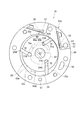
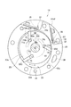
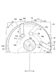
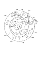
- FIG. 4 is an explanatory diagram showing an enlarged main part of the compressed block shown in FIG.
- FIG. 5 is an explanatory diagram showing a virtual example when the first supply unit and the second supply unit of the high-pressure supply groove of FIG. 3 are arranged apart from each other so that the back pressure space of the vane groove does not communicate with either. is there.
- FIG. 1 is a cross-sectional view showing an overall configuration of a vane rotary type gas compressor according to a first embodiment of the present invention.
- 2 is a cross-sectional view taken along line II of the gas compressor of FIG. 3 is a cross-sectional view taken along the line II-II of the gas compressor of FIG
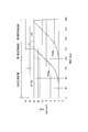
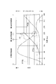
- FIG. 6 is a graph showing changes in the pressure in the compression chamber and the pressure in the back pressure space of the vane in the vane groove according to the rotation angle of the rotor in FIG.
- FIG. 7 is an explanatory diagram illustrating a communication cross-sectional area between the first supply portion, the second supply portion, and the back pressure space of the vane groove of the high pressure supply groove of FIG. 3.
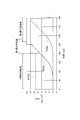
- FIG. 8 is a graph showing changes in the pressure in the compression chamber and the pressure in the back pressure space of the vane groove according to the rotation angle of the rotor in FIG. 3.
- FIG. 9 is a cross-sectional view of a vane rotary type gas compressor according to the second embodiment of the present invention at a position corresponding to the cross-sectional view of FIG. FIG.
- FIG. 10 is a cross-sectional view of a vane rotary type gas compressor according to the second embodiment of the present invention at a position corresponding to the cross-sectional view of FIG.
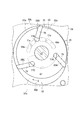
- FIG. 11 is an explanatory diagram showing an enlarged main part of the compressed block shown in FIG.
- FIG. 12 is an explanatory diagram showing a positional relationship between a region where the protruding stroke of the vane with respect to the vane groove decreases at a certain rate or more and a distance between the first supply unit and the second supply unit in the compression block shown in FIG. It is.
- FIG. 13 is a graph showing changes in the pressure in the compression chamber and the pressure in the back pressure space of the vane groove according to the rotation angle of the rotor in FIG. 12.
- FIG. 14 shows an interval between the region, the first supply unit, and the second supply unit in a period in which the vane slides in a region where the protruding stroke of the vane with respect to the vane groove decreases at a certain rate or more in the compression block shown in FIG.
- FIG. 15 is a graph showing changes in the pressure in the compression chamber and the pressure in the back pressure space of the vane groove according to the rotation angle of the rotor in FIG. 10.
- FIG. 16 is an explanatory view showing the inside of a compression block of a conventional gas compressor.
- FIG. 17 is a graph showing changes in the pressure in the compression chamber and the pressure in the back pressure space of the vane groove according to the rotation angle of the rotor in FIG. 16.
- a gas compressor 1 As shown in FIG. 1, a gas compressor 1 according to this embodiment includes a substantially cylindrical housing 2, a compression unit 3 accommodated in the housing 2, and a motor unit 4 that transmits a driving force to the compression unit 3. And an inverter unit 5 that is fixed to the housing 2 and controls the driving of the motor unit 4.
- the housing 2 includes a front head 7 in which a suction port (not shown) is formed and a bottomed cylindrical rear case 9 whose opening is closed by the front head 7.
- the compression part 3 is fixed to the inner wall 13 of the rear case 9.
- a suction chamber 11 is formed on one side of the compression unit 3 so as to partition the inside of the housing 2, and a discharge chamber 15 is formed on the other side.
- a discharge port (not shown) that connects the discharge chamber 15 and the refrigeration cycle is formed on the outer periphery of the rear case 9.
- an oil reservoir 17 in which oil O for maintaining the lubricity of the compression unit 3 is stored is formed below the discharge chamber 15.
- the compression unit 3 protrudes and retracts from the compression block 19 forming the cylinder chamber 33, the oil separator 21 fixed to the compression block 19, the rotor 23 rotatably accommodated in the cylinder chamber 33, and the rotor 23.
- a vane 25 (see FIG. 3) that partitions the cylinder chamber 33 and a drive shaft 27 that is fixed integrally with the rotor 23 and transmits a driving force are provided.
- the compression block 19 includes a cylinder block 29, a pair of side blocks 31, and a cylinder chamber 33 formed on the inner periphery of the cylinder block 29.
- the cylinder block 29 has an elliptical cylinder chamber 33 distorted inside.
- the opening of the cylinder chamber 33 is closed by holding both ends of the cylinder block 29 by a pair of side blocks 31.
- the rotor 23 is arranged so that one location is in contact with the inner wall of the cylinder chamber 33, and is arranged with the position shifted from the center (center of gravity) of the cylinder chamber 33 as the rotation center.
- a vane groove 75 opened on the outer peripheral surface of the rotor 23 and a back pressure space 77 on the back side of the vane 25 are provided.
- the cylinder chamber 33 is partitioned into a plurality of rotation directions X of the rotor 23 by a plurality of vanes 25 that appear and disappear from a plurality of vane grooves 75 of the rotor 23. Thereby, a plurality of compression chambers 33a, 33b, 33c are formed between the inner peripheral surface 33d of the cylinder chamber 33 and the outer peripheral surface 23a of the rotor 23.
- the cylinder block 29 includes a suction hole 39 for sucking refrigerant into the cylinder chamber 33, a discharge hole 35 for discharging refrigerant compressed in the cylinder chamber 33, an on-off valve 37 for opening and closing the discharge hole 35, and a side block. And a cylinder-side oil supply passage 41 communicating with the 31 oil supply passages.
- the pair of side blocks 31 includes a front side block 31a and a rear side block 31b, and an oil separator 21 is fixed to the rear side block 31b.
- the front side block 31a communicates with the front side end face 43 that contacts the cylinder block 29, the suction hole 39, a suction hole (not shown) that sucks refrigerant from the suction chamber 11, and a front side that rotatably supports the drive shaft 27.
- a bearing 47 and a front side oil supply path 49 communicating with the cylinder side oil supply path 41 are provided.
- the front-side end face 43 is provided with a pressure supply groove, and the pressure supply groove supplies an intermediate pressure (intermediate pressure) higher than the sucked refrigerant and lower than the pressure of the discharged refrigerant to the back pressure space 77.
- Intermediate pressure supply groove 51 and high pressure supply groove 53 provided at a position facing high pressure supply groove 69 on the rear side block 31b side.
- the front side bearing 47 is formed with an annular front side annular groove 55 and is provided in communication with one end side of the front side oil supply passage 49.
- the other end side of the front side oil supply passage 49 is in communication with the cylinder side oil supply passage 41.
- the rear side block 31 b is configured to freely rotate the rear side end face 57 that contacts the cylinder block 29, the oil supply hole 59 that sucks oil O stored below the discharge chamber 15, and the drive shaft 27.
- a rear-side bearing 63 to be supported and a rear-side oil supply passage 59b communicating with the cylinder-side oil supply passage 41 are provided.
- the rear-side end surface 57 has a discharge hole 61 for discharging the refrigerant compressed in the cylinder chamber 33, and an intermediate pressure that is higher than the pressure (suction pressure) of the sucked refrigerant and lower than the pressure (discharge pressure) of the discharged refrigerant.
- An intermediate pressure supply groove 67 for supplying oil to the back pressure space 77 (corresponding to an intermediate pressure supply portion in claims) and high pressure oil that is the pressure of the discharged refrigerant (discharge pressure) are supplied to the back pressure space 77.
- a high-pressure supply groove 69 (corresponding to a high-pressure supply part in claims).
- the high-pressure supply groove 69 is divided into a first supply unit 69a (corresponding to the upstream supply unit) and a second supply unit 69b (corresponding to the downstream supply unit) that are independent from each other in the rotational direction X of the rotor 23. Yes.
- the first supply portion 69a and the second supply portion 69b have high-pressure supply passages 71a and 71b, respectively.
- One end side of each of the high-pressure supply passages 71a and 71b communicates with the rear-side annular groove 73.
- the end sides communicate with the first supply unit 69a and the second supply unit 69b, respectively.
- the high-pressure supply groove 53 of the front side block 31a facing the high-pressure supply groove 69 is also divided into two supply parts (not shown) similar to the first supply part 69a and the second supply part 69b.
- the back pressure space 77 (see FIGS. 3 and 4) formed in the rotor 23 communicates with the intermediate pressure supply grooves 51 and 67 in the first half position of compression, and high pressure in the second half position of compression, as the rotor 23 rotates. It communicates with the supply grooves 53 and 69.
- the compression chamber 33b moved from the suction process to the compression process by the rotation of the rotor 23, and the compression moved from the compression process to the discharge process located downstream of the compression chamber 33b in the rotation direction X of the rotor 23.
- the back pressure space 77B of the vane groove 75 of the vane 25B that partitions the chamber 33a ends communication with the intermediate pressure supply groove 67. Then, the back pressure space 77B communicates with the first supply unit 69a located on the upstream side in the rotation direction X of the rotor 23.
- the back pressure space 77A of the vane groove 75 of the vane 25A that precedes the downstream side of the vane 25B in the rotation direction X of the rotor 23 has already finished communicating with the first supply unit 69a, and is downstream in the rotation direction X. It communicates with the second supply part 69b located on the side.
- the back pressure space 77A of the preceding vane 25A and the back pressure space 77B of the next vane 25B following the vane 25A do not communicate with the first supply unit 69a at the same time.
- the first supply unit 69a is formed. That is, in the rotation direction X of the rotor 23, the angle range in which the first supply unit 69a extends is smaller than the difference between the angle at which the back pressure space 77A is located and the angle at which the back pressure space 77B is located. ing. That is, the distance between the back pressure space 77A and the back pressure space 77B in the rotation direction X of the rotor 23 is set wider than the width of the first supply unit 69a.
- the back pressure space 77A of the preceding vane 25A and the back pressure space 77B of the next vane 25B following the vane 25A do not communicate with the second supply unit 69b at the same time.
- the second supply part 69b is formed in the shape. That is, in the rotation direction X of the rotor 23, the angle range in which the second supply portion 69b extends is smaller than the difference between the angle at which the back pressure space 77A is located and the angle at which the back pressure space 77B is located. ing. That is, the distance between the back pressure space 77A and the back pressure space 77B in the rotation direction X of the rotor 23 is set wider than the width of the second supply unit 69b.
- the angle range in which the first supply unit 69a extends and the second supply unit 69b extend As described above, based on the difference between the angle at which the back pressure space 77A is located and the angle at which the back pressure space 77B is located, the angle range in which the first supply unit 69a extends and the second supply unit 69b extend. Restrictions on the angle range to be generated occur.
- the angle range in which the first supply unit 69a extends and the second supply unit 69b extend are constraints on the angular range.
- the angle range in which the first supply unit 69a extends and the second supply unit 69b extend are constraints on the angular range.
- the shapes of the first supply unit 69a and the second supply unit 69b are determined based on the angle at which the back pressure space 77 is positioned in the rotation direction X of the rotor 23.
- the distance between the intermediate pressure supply groove 67 and the first supply portion 69a in the rotational direction X of the rotor 23 and the distance between the second supply portion 69b and the intermediate pressure supply groove 67 are the back in the rotational direction X of the rotor 23. It is set wider than the width of the pressure space 77.
- the oil supply hole 59 is formed in communication with the rear side oil supply path 59a, and is branched from the rear side oil supply path 59a to form a rear side oil supply path 59b.
- the rear side oil supply path 59 b communicates with the cylinder side oil supply path 41.
- the rear side bearing 63 is formed with an annular rear side annular groove 73 and communicates with the rear side communication path 65.
- the rear side communication passage 65 has one end communicating with the rear annular groove 73 and the other end opening into the high pressure supply groove 69.
- the oil separator 21 is fixed to the rear side block 31b, and the refrigerant compressed in the cylinder chamber 33 flows into the oil separator 21 to separate the refrigerant and the oil O from each other.
- the drive shaft 27 is fixed to the rotor 23 on one side and is rotatably supported by bearings 47 and 63 of the side blocks 31a and 31b.
- the motor unit 4 is fixed to the other side of the drive shaft 27.
- the motor unit 4 includes a stator 79 fixed to the inner wall 13 of the rear case 9 and a motor rotor 81 that is rotatably arranged on the inner peripheral side of the stator 79 and rotates by magnetic force.
- the motor rotor 81 is rotated by the magnetic force, so that the rotational driving force is transmitted to the compression unit 3.
- the distance between the first supply unit 69 a and the second supply unit 69 b in the rotation direction X of the rotor 23 is the distance of the back pressure space 77 in the rotation direction X of the rotor 23. It is set narrower than the width.
- FIG. 5 is an explanatory diagram showing a virtual example when the first supply unit and the second supply unit of the high-pressure supply groove of FIG. 3 are arranged apart from each other so that the back pressure space of the vane groove does not communicate with either. is there.
- FIG. 6 is a graph showing changes in the pressure P33a of the compression chamber 33a, the pressure P33b of the compression chamber 33b, and the back pressure space 77B according to the rotation angle of the rotor.
- the high-pressure supply groove 69 includes a first supply part 69a and a second supply part 69b, and the back pressure space 77B is formed by the first supply part as the rotor 23 rotates in the rotation direction X. After communicating with 69a, it communicates with the second supply unit 69b.
- the communication destination of the back pressure space 77B is the first.
- the vane 25B accommodated in the vane groove 75 where the back pressure space 77B is located between the first supply unit 69a and the second supply unit 69b is compressed by the compression chambers 33a and 33b partitioned by the vane 25B. Since the discharge process is performed from the latter stage, a force in the direction of immersing in the vane groove 75 is received from the inner peripheral surface 33 d of the cylinder chamber 33. That is, when the back pressure space 77B is located between the first supply part 69a and the second supply part 69b, the volume of the back pressure space 77B is decreasing.
- the back pressure space 77B since the back pressure space 77B is not in communication with either the first supply unit 69a or the second supply unit 69b at this position, the reduced pressure of the back pressure space 77B is high except for the back pressure space 77B. It cannot be evacuated anywhere. For this reason, as shown in P1 of FIG. 6, the pressure in the back pressure space 77 temporarily increases in the middle of the transition of the communication destination of the back pressure space 77B from the first supply unit 69a to the second supply unit 69b. To do. That is, since the back pressure space 77B does not communicate with either the first supply unit 69a or the second supply unit 69b, the pressure in the back pressure space 77 is temporarily increased as shown in P1 of FIG. To rise.
- a similar phenomenon may occur in a state where the vane 25A and the vane 25C are not in communication with either the first supply unit 69a or the second supply unit 69b.
- the back pressure space 77 communicates with the first supply unit 69a and the second supply unit 69b, the high-pressure supply that supplies high-pressure oil O to the first supply unit 69a and the second supply unit 69b.
- the high pressure in the back pressure space 77 can be retracted to the passages 71a, 71b, the rear side communication passage 65, the rear side annular groove 73, the rear side oil supply passage 59a, and the oil supply hole 59.
- the total of the above-described communication cross-sectional areas S1 and S3 reaches the oil supply hole 59 from the high-pressure supply passages 71a and 71b.
- the first supply unit 69a and the second supply unit 69b are spaced apart in the rotation direction X of the rotor 23 by an interval that is equal to or larger than the minimum passage cross-sectional area in the supply path of high-pressure oil O to the first supply unit 69a and the second supply unit 69b. Between the two.
- a current flows through a coil wound around the stator 79 of the motor unit 4 by the control of the inverter unit 5 shown in FIG.
- a current flows through the coil, a magnetic force is generated, and the motor rotor 81 disposed on the inner periphery of the stator 79 rotates.
- the refrigerant flows into the suction chamber 11, and the refrigerant is sucked from the suction chamber 11 into the cylinder chamber 33 through a suction hole (not shown) of the front side block 31a (suction process).
- the refrigerant sucked into the cylinder chamber 33 forms compression chambers 33a, 33b, 33c in the cylinder chamber 33 by the plurality of vanes 25, and the rotor 23 rotates to compress the refrigerant in the compression chambers 33a, 33b, 33c. (Compression process).
- the refrigerant compressed in the cylinder chamber 33 pushes the open / close valve 37 to discharge from the discharge hole 35 (discharge process), and is discharged from the discharge hole 61 to the discharge chamber 15 through the oil separator 21.
- the refrigerant discharged from the discharge hole 61 is separated into refrigerant and oil O by the oil separator 21, and the refrigerant is discharged from a discharge port (not shown) to a refrigeration cycle (not shown). It is stored in.
- the oil stored below the discharge chamber 15 is supplied from the oil supply hole 59 of the rear side block 31b to the rear side bearing 63 through the rear side oil supply path 59a.
- the high-pressure oil supplied to the rear-side bearing 63 is squeezed between the drive shaft 27 and thereby is higher than the pressure (suction pressure) of the sucked refrigerant and lower than the pressure (discharge pressure) of the discharged refrigerant.
- the oil O that has become the intermediate pressure is supplied to the intermediate pressure supply groove 67 through the gap between the drive shaft 27 and the rear side block 31b.
- the intermediate pressure oil O supplied to the intermediate pressure supply groove 67 supplies intermediate pressure to the back pressure space 77 from the refrigerant suction process to the compression process range, and the vane groove 75 supplies the vane.
- Intermediate pressure is supplied to the back surface of the vane 25 so that 25 protrudes.
- the high-pressure oil O supplied to the rear-side bearing 63 passes through the first supply portion 69a and the first supply portion 69a of the high-pressure supply groove 69 from the high-pressure supply passages 71a and 71b that open to the rear-side end surface 57 via the rear-side communication passage 65. 2 is supplied to the supply unit 69b.
- the high-pressure oil O supplied to the first supply unit 69a and the second supply unit 69b supplies high pressure to the back pressure space 77 from the refrigerant compression process to the discharge process as shown in FIG.
- High pressure is supplied to the back surface of the vane 25 so that the vane 25 protrudes from the groove 75.
- the first supply unit 69 a and the second supply unit 69 b communicate with the corresponding supply units (not shown) of the high pressure supply groove 53 on the front side block 31 a side via the back pressure space 77, and the high pressure supply groove 53.
- High pressure is also supplied from each supply section to the back pressure space 77.
- the high-pressure oil O flows from the oil supply hole 59 into the rear side oil supply path 59a, branches from the rear side oil supply path 59a, passes through the rear side oil supply path 59b, and passes through the cylinder side oil supply path 41. Then, the oil is supplied from the front oil supply passage 49 to the front bearing 47.
- the high pressure oil O supplied to the front side bearing 47 becomes an intermediate pressure by being squeezed between the drive shaft 27, and the oil O which has become the intermediate pressure is a gap between the drive shaft 27 and the front side block 31a. And is supplied to the intermediate pressure supply groove 51.
- the high-pressure oil O supplied from the high-pressure supply grooves 53 and 69 of the front side block 31a and the rear side block 31b is supplied to the back pressure space 77 of the rotor 23 at the second half rotation position of the rotor 23, and passes through the vane 25 from the vane groove 75.
- the back pressure to make it protrude is given.
- the back pressure space 77 of the vane groove 75 that has finished communicating with the intermediate pressure supply groove 67 communicates with the first supply part 69a of the high pressure supply groove 69, and the first supply part High pressure is supplied from 69a.
- the back pressure space 77 communicates with the first supply unit 69a before the back pressure space 77 of the next vane groove 75 located on the upstream side in the rotation direction X communicates with the first supply unit 69a.
- the back pressure space communicates with the second supply unit 69b located on the downstream side in the rotation direction X independent of the first supply unit 69a, and the high pressure is supplied again.
- the back pressure space 77 that has finished communicating with the intermediate pressure supply groove 67 communicates with the first supply portion 69 a of the high pressure supply groove 69, the back pressure space 77 is adjacent to the downstream side in the rotation direction X.
- the preceding back pressure space 77 does not communicate with the first supply unit 69a at the same time.
- the back pressure space 77A communicates with the first supply unit 69a before the back pressure space 77B of the next vane groove 75 located on the upstream side in the rotation direction X communicates with the first supply unit 69a. Is shown, and the high pressure is again supplied to the back pressure space 77A in communication with the second supply unit 69b located on the downstream side in the rotation direction X independent of the first supply unit 69a. ing.
- the back pressure space 77B communicates with the first supply portion 69a of the high pressure supply groove 69, the preceding back pressure space 77A adjacent to the downstream side in the rotation direction X of the back pressure space 77B is the first supply. There is no simultaneous communication with the portion 69a.
- a similar relationship is established not only between the back pressure space 77A and the back pressure space 77B, but also between the back pressure space 77B and the back pressure space 77C, and between the back pressure space 77C and the back pressure space 77A.
- the pressure in the preceding back pressure space 77 is temporarily increased by the intermediate pressure before the pressure increases to the high pressure in the following back pressure space 77 that follows. Can be prevented from being lowered from high pressure. Thereby, it is possible to prevent the occurrence of chattering in which the vane 25 repeatedly contacts and separates from the inner peripheral surface 33d of the cylinder chamber 33 due to temporary pressure reduction of the back pressure space 77 of the vane 25 in the first half of the compression process.
- the back pressure space 77 ends the communication with the second supply unit 69b before the back pressure space 77 of the next vane groove 75 located on the upstream side in the rotation direction X communicates with the second supply unit 69b. . Therefore, when the back pressure space 77 that has finished communicating with the first supply portion 69 a of the high pressure supply groove 69 communicates with the second supply portion 69 b of the high pressure supply groove 69, the back pressure space 77 in the rotational direction X The preceding back pressure space 77 adjacent to the downstream side does not communicate with the second supply unit 69b at the same time.
- FIG. 8 is a graph showing changes in the pressure P33a of the compression chamber 33a, the pressure P33b of the compression chamber 33b, and the back pressure space 77B according to the rotation angle of the rotor.
- the high-pressure supply groove 69 includes a first supply part 69a and a second supply part 69b, and the back pressure space 77B is formed by the first supply part as the rotor 23 rotates in the rotation direction X. After communicating with 69a, it communicates with the second supply unit 69b.
- the back pressure space 77 and the first supply unit 69a when the communication destination of the back pressure space 77 moves from the first supply unit 69a to the second supply unit 69b
- the total of the communication cross-sectional areas S1 and S3 with the second supply unit 69b is equal to or larger than the minimum passage cross-sectional area in the high-pressure oil O supply path to the first supply unit 69a and the second supply unit 69b.
- the back pressure space 77 is connected to at least one of the first supply part 69a or the second supply part 69b and the minimum passage.
- the second supply portion 69b of the high-pressure supply groove 69 has a shape as large as possible in the rotational direction X as long as two back pressure spaces 77 adjacent to each other in the rotational direction X of the rotor 23 do not communicate with each other. It is desirable. By doing so, the back pressure space 77 in which the pressure is increased from the intermediate pressure toward the high pressure by communication with the first supply unit 69a is changed from the early stage of the compression process of the compression chambers 33a, 33b, 33c to the second supply unit. 69 b and then the pressure in the back pressure space 77 can be stabilized at a high pressure.
- the discharge process of the compression chambers 33a, 33b, and 33c can be started at an early stage, and the on-off valve 37 of the discharge hole 35 is opened at an early stage, so that the high-pressure refrigerant in the compression chambers 33a, 33b, and 33c. Can be efficiently and sufficiently discharged, and the refrigerant compression efficiency can be improved.
- the high-pressure supply groove 69 is divided into two mutually independent first supply part 69a and second supply part 69b in the rotation direction X.
- the present invention is also applicable when the high-pressure supply groove 69 is divided into three or more supply parts in the rotation direction X. In that case, when the back pressure space 77 moves across the two supply parts adjacent in the rotation direction X, the upstream supply part and the communication cross-sectional area of the downstream supply part and the back pressure space 77 are The relationship of the invention will apply.
- FIGS. 9 and 10 show the structure of the vane rotary type gas compressor according to the second embodiment.
- the second embodiment has a rear side block 31b2 that is different from the rear side block 31b of the first embodiment.
- the configuration other than the rear side block 31b2 is the same as that of the first embodiment.
- the same components as those in the first embodiment are denoted by the same reference numerals in the drawings, and the description thereof is omitted.
- a gap 69c having a dimension equal to or larger than the back pressure space 77 of the vane groove 75 is provided between the first supply part 69a and the second supply part 69b. That is, the interval 69 c provided in the first supply unit 69 a and the second supply unit 69 b is set wider than the width of the back pressure space 77 of the vane groove 75.
- the compression chamber 33b moved from the suction process to the compression process by the rotation of the rotor 23, and the compression positioned downstream from the compression chamber 33b in the rotation direction X of the rotor 23 and moved from the compression process to the discharge process.
- a back pressure space 77B of the vane groove 75 of the vane 25B partitioning the chamber 33a communicates with the first supply portion 69a of the high pressure supply groove 69.
- the back pressure space 77B ends communication with the first supply unit 69a, and the back pressure space 77B is connected to the first supply unit 69a and the second supply unit 69a. It communicates with an interval 69c provided between the supply parts 69b. At this time, the back pressure space 77B does not communicate with either the first supply unit 69a or the second supply unit 69b.
- the region shown in the range of FIG. 12A on the inner peripheral surface 33d of the cylinder chamber 33 that is, the rate at which the protrusion stroke of the vane 25B with respect to the vane groove 75 with a rotation in the rotation direction X of the rotor 23 is a certain level or more It is assumed that when the vane 25B is in sliding contact with the area that decreases in step, a space 69c is disposed at a position where the back pressure space 77B communicates.
- FIG. 12 is an explanatory diagram showing a positional relationship between a region where the projecting stroke of the vane 25B with respect to the vane groove 75 decreases at a certain rate or more and the interval 69c.
- the volume of the back pressure space 77B decreases at a rate corresponding to the reduction rate of the protruding stroke of the vane 25B in a state where the back pressure space 77B is blocked from the first supply unit 69a and the second supply unit 69b. As shown at P1 in FIG. 13, the pressure in the back pressure space 77B temporarily rises.
- a predetermined threshold value at which the reduction rate of the protruding stroke of the vane 25 with respect to the vane groove 75 due to the rotation of the rotor 23 in the rotation direction X on the inner peripheral surface 33d of the cylinder chamber 33 is lower than the above-described constant rate.
- the region having the following reduction rate is a region where the reduction rate of the protruding stroke is small.
- the inner peripheral surface 33d of the cylinder chamber 33 is as shown in FIG. (A) a region in which the protruding stroke from the vane groove 75 of the vane 25 slidably contacting the inner peripheral surface 33d of the cylinder chamber 33 increases as the rotor 23 rotates in the rotation direction X; (B) a region in which the protrusion stroke from the vane groove 75 of the vane 25 slidably contacting the inner peripheral surface 33d of the cylinder chamber 33 decreases as the rotor 23 rotates in the rotation direction X; (C) The protrusion stroke from the vane groove 75 of the vane 25 slidably in contact with the inner peripheral surface 33d of the cylinder chamber 33 decreases with the rotation of the rotor 23 in the rotation direction X, and the rate of decrease is the region (b).
- the back pressure space 77 is spaced at a position where it communicates. 69c is arranged.
- the back pressure space 77 that has finished communicating with the intermediate pressure supply groove 67 communicates with the first supply portion 69 a of the high pressure supply groove 69
- the back pressure space 77 is downstream in the rotational direction X.
- the preceding back pressure space 77 adjacent to the first supply portion 69a does not communicate with the first supply portion 69a at the same time.
- the back pressure space 77 that has finished communicating with the intermediate pressure supply groove 67 communicates with the first supply portion 69 a of the high pressure supply groove 69, the back pressure space 77 is adjacent to the downstream side in the rotation direction X.
- the preceding back pressure space 77 does not communicate with the first supply unit 69a at the same time.
- the pressure in the preceding back pressure space 77 is temporarily increased by the intermediate pressure before the pressure increases to the high pressure in the following back pressure space 77 that follows. Can be prevented from being lowered from high pressure. Thereby, it is possible to prevent the occurrence of chattering in which the vane 25 repeatedly contacts and separates from the inner peripheral surface 33d of the cylinder chamber 33 due to temporary pressure reduction of the back pressure space 77 of the vane 25 in the first half of the compression process.
- the back pressure space 77 ends the communication with the second supply unit 69b before the back pressure space 77 of the next vane groove 75 located on the upstream side in the rotation direction X communicates with the second supply unit 69b. . Therefore, when the back pressure space 77 that has finished communicating with the first supply portion 69 a of the high pressure supply groove 69 communicates with the second supply portion 69 b of the high pressure supply groove 69, the back pressure space 77 in the rotational direction X The preceding back pressure space 77 adjacent to the downstream side does not communicate with the second supply unit 69b at the same time.
- the vane 25 repeatedly contacts and separates from the inner peripheral surface 33 d of the cylinder chamber 33 due to the temporary pressure reduction of the back pressure space 77 of the vane 25 in the later stage of the compression process or the discharge process. Generation of chattering can be prevented.
- the back pressure space 77 when the back pressure space 77 communicates with the gap 69c between the first supply portion 69a and the second supply portion 69b, the back pressure space 77 has a vane groove 75.
- the first supply unit 69a and the second supply unit are arranged so that the accommodated vane 25 is in sliding contact with the region (c) in which the reduction rate of the protruding stroke of the vane 25 accompanying the rotation of the rotor 23 in the rotation direction X is the lowest.
- An interval 69c with respect to 69b is located.
- the second supply portion 69b of the high-pressure supply groove 69 has a shape as large as possible in the rotational direction X as long as two back pressure spaces 77 adjacent to each other in the rotational direction X of the rotor 23 do not communicate with each other. It is desirable. By doing so, the back pressure space 77 in which the pressure is increased from the intermediate pressure toward the high pressure by communication with the first supply unit 69a is changed from the early stage of the compression process of the compression chambers 33a, 33b, 33c to the second supply unit. 69 b and then the pressure in the back pressure space 77 can be stabilized at a high pressure.
- the discharge process of the compression chambers 33a, 33b, and 33c can be started at an early stage, and the on-off valve 37 of the discharge hole 35 is opened at an early stage, so that the high-pressure refrigerant in the compression chambers 33a, 33b, and 33c. Can be efficiently and sufficiently discharged, and the refrigerant compression efficiency can be improved.
- the interval 69c provided in the first supply unit 69a and the second supply unit 69b is set to be wider than the width of the back pressure space 77 of the vane groove 75. May be smaller than the back pressure space 77 in the rotational direction X of the rotor 23.
- the back pressure space 77 straddles the interval 69c when the communication destination of the back pressure space 77 shifts from the first supply unit 69a of the high pressure supply unit 69 to the second supply unit 69b, it overlaps with the interval 69c.
- the communication cross-sectional area with respect to each supply part 69a, 69b of the back pressure space 77 decreases.
- the back pressure space 77 is reduced by the reduced volume.
- the efficiency of evacuating the internal high pressure to the first supply unit 69a and the second supply unit 69b decreases.
- the pressure in the back pressure space 77 temporarily rises in the later stage of the compression process and in the discharge process, and the force with which the vane 25 presses the inner peripheral surface 33d of the cylinder chamber 33 increases more than necessary, and the vane 25 and the cylinder chamber are increased.
- the sliding resistance with the inner peripheral surface 33d of 33 may increase.
- the area of the inner peripheral surface 33d of the cylinder chamber 33 that the vane 25 is in sliding contact with when the back pressure space 77 communicates with the interval 69c is used as a guideline for the reduction rate of the protruding stroke of the vane 25 relative to the vane groove 75 Decided.
- the upper limit value of the allowable range of the reduction rate of the protruding stroke of the vane 25 with respect to the vane groove 75 is determined according to the allowable range for the temporary increase of the pressure in the back pressure space 77.
- a region on the inner peripheral surface 33d of the cylinder chamber 33 is determined such that the reduction rate of the protruding stroke of the vane 25 is equal to or less than this threshold value. What is necessary is just to arrange
- the back pressure space 77 is reduced due to a decrease in the protruding stroke of the vane 25 during the period in which the back pressure space 77 communicates with the gap 69c between the first supply portion 69a and the second supply portion 69b.
- Temporary pressure increase can be within an allowable range. Therefore, the sliding resistance of the vane 25 with respect to the inner peripheral surface 33d of the cylinder chamber 33 increases due to the temporary pressure increase in the back pressure space 77 in the later stage of the compression process or in the discharge process, and the power necessary for the rotation of the rotor 23 increases. And the operation performance as the gas compressor 1 can be maintained.
- the high-pressure supply groove 69 is divided into two mutually independent first supply part 69a and second supply part 69b in the rotation direction X.
- the present invention is also applicable when the high-pressure supply groove 69 is divided into three or more supply parts in the rotation direction X. In that case, the relationship of the present invention is applied to the relative position between the interval between two supply parts adjacent in the rotation direction X and the inner peripheral surface of the cylinder chamber.
- the second supply portion 69 b of the high-pressure supply groove 69 has a size that prevents the two back pressure spaces 77 adjacent in the rotation direction X of the rotor 23 from communicating simultaneously.
- the second supply unit 69b may have a larger dimension than the first supply unit 69a.
- the discharge process of the compression chambers 33a, 33b, and 33c can be started at an early stage, and the on-off valve 37 of the discharge hole 35 is opened at an early stage, so that the high-pressure refrigerant in the compression chambers 33a, 33b, and 33c. Can be efficiently and sufficiently discharged, and the refrigerant compression efficiency can be improved.
- the high pressure supply groove 69 is rotated in the rotational direction X.
- the first supply unit 69a and the second supply unit 69b are divided into two parts.
- the present invention is also widely applicable when the high-pressure supply groove 69 is divided into three or more supply parts in the rotation direction X.
- the two back parts adjacent to each other in the rotation direction X of the supply part communicating with the back pressure space 77 in a state where the pressure of the back pressure space 77 rises from the intermediate pressure to the high pressure. If the pressure spaces 77 are formed so as not to communicate with each other at the same time, the same effects as those of the above-described embodiments can be obtained.
- the supply portion located second from the most upstream side in the rotation direction X is an object to be formed in a shape in which at least two adjacent back pressure spaces 77 in the rotation direction X do not communicate with each other at the same time.
- the third and subsequent supply units from the most upstream side also communicate with the back pressure space 77 when the pressure in the back pressure space 77 is increasing from the intermediate pressure to the high pressure.
- the pressure space 77 serves as a target supply unit formed into a shape that does not communicate with each other at the same time.
- the back pressure space of the vane groove that has finished communicating with the intermediate pressure supply unit is supplied with high pressure until the refrigerant pressure in the compression chamber partitioned by the vane housed in the vane groove reaches the maximum pressure.
- High pressure is supplied from the first supply unit in communication with the first supply unit. After that, the back pressure space is communicated with the first supply unit before the back pressure space of the next vane groove on the upstream side in the rotation direction communicates with the first supply unit.
- the high pressure is supplied again by communicating with the next independent second supply section.
- the preceding back pressure space adjacent to the downstream side in the rotational direction of the back pressure space is , It does not communicate with the first supply unit at the same time. Therefore, the pressure in the preceding back pressure space is temporarily prevented from being lowered from the high pressure by the intermediate pressure in the following back pressure space, and the chattering of the vane due to the temporary pressure reduction in the vane back pressure space is prevented. can do.
Landscapes
- Engineering & Computer Science (AREA)
- Mechanical Engineering (AREA)
- General Engineering & Computer Science (AREA)
- Rotary Pumps (AREA)
- Applications Or Details Of Rotary Compressors (AREA)
Abstract
La présente invention concerne un espace de contre-pression (77) d'une rainure d'aube (75) qui ne communique plus avec une rainure d'alimentation en pression intermédiaire (67) communiquant avec une première partie d'alimentation (69a) et alimenté en haute pression à partir de la première partie d'alimentation (69a) jusqu'à ce que la pression de réfrigérant des chambres de compression (33a, 33b, 33c) divisées par les aubes (25) des rainures d'aube (75) atteigne la pression maximale. Au point au niveau duquel l'espace de contre-pression (77) qui n'est plus est en communication avec la rainure d'alimentation en pression intermédiaire (67) communique avec la première partie d'alimentation (69a) d'une rainure d'alimentation en haute pression (69), l'espace de contre-pression avant (77) sur le côté aval dans la direction de rotation X et adjacent à cet espace de contre-pression (77) ne communique plus avec la première partie d'alimentation (69a).
Priority Applications (3)
| Application Number | Priority Date | Filing Date | Title |
|---|---|---|---|
| CN201580070926.0A CN107110158B (zh) | 2014-12-24 | 2015-12-16 | 气体压缩机 |
| US15/539,443 US20170350391A1 (en) | 2014-12-24 | 2015-12-16 | Gas compressor |
| EP15872843.6A EP3239530A4 (fr) | 2014-12-24 | 2015-12-16 | Compresseur de gaz |
Applications Claiming Priority (6)
| Application Number | Priority Date | Filing Date | Title |
|---|---|---|---|
| JP2014260500A JP5831619B1 (ja) | 2014-12-24 | 2014-12-24 | 気体圧縮機 |
| JP2014-260500 | 2014-12-24 | ||
| JP2014-260492 | 2014-12-24 | ||
| JP2014-260491 | 2014-12-24 | ||
| JP2014260491A JP5878970B1 (ja) | 2014-12-24 | 2014-12-24 | 気体圧縮機 |
| JP2014260492A JP5878971B1 (ja) | 2014-12-24 | 2014-12-24 | 気体圧縮機 |
Publications (1)
| Publication Number | Publication Date |
|---|---|
| WO2016104274A1 true WO2016104274A1 (fr) | 2016-06-30 |
Family
ID=56150299
Family Applications (1)
| Application Number | Title | Priority Date | Filing Date |
|---|---|---|---|
| PCT/JP2015/085193 Ceased WO2016104274A1 (fr) | 2014-12-24 | 2015-12-16 | Compresseur de gaz |
Country Status (4)
| Country | Link |
|---|---|
| US (1) | US20170350391A1 (fr) |
| EP (1) | EP3239530A4 (fr) |
| CN (1) | CN107110158B (fr) |
| WO (1) | WO2016104274A1 (fr) |
Families Citing this family (6)
| Publication number | Priority date | Publication date | Assignee | Title |
|---|---|---|---|---|
| JP6825530B2 (ja) * | 2017-09-29 | 2021-02-03 | 株式会社豊田自動織機 | ベーン型圧縮機 |
| DE102017128972B4 (de) * | 2017-12-06 | 2025-11-27 | Joma-Polytec Gmbh | Vakuumpumpe |
| KR102223283B1 (ko) | 2018-11-16 | 2021-03-05 | 엘지전자 주식회사 | 베인 로터리 압축기 |
| CN111997898A (zh) * | 2020-09-10 | 2020-11-27 | 常州康普瑞汽车空调有限公司 | 一种旋叶式压缩机背压优化结构及方法 |
| CN115573905B (zh) * | 2022-09-20 | 2026-02-17 | 江苏梅花机械有限公司 | 一种真空泵及其控制方法、以及农业机械用制动装置 |
| KR102765935B1 (ko) * | 2023-03-16 | 2025-02-12 | 엘지전자 주식회사 | 로터리 압축기 |
Citations (4)
| Publication number | Priority date | Publication date | Assignee | Title |
|---|---|---|---|---|
| JPH01141391U (fr) * | 1988-03-23 | 1989-09-28 | ||
| JP2004092494A (ja) * | 2002-08-30 | 2004-03-25 | Calsonic Compressor Seizo Kk | 気体圧縮機 |
| JP2006112331A (ja) * | 2004-10-15 | 2006-04-27 | Matsushita Electric Ind Co Ltd | 圧縮機 |
| JP2013204557A (ja) * | 2012-03-29 | 2013-10-07 | Toyota Industries Corp | タンデム式ベーン型圧縮機 |
Family Cites Families (7)
| Publication number | Priority date | Publication date | Assignee | Title |
|---|---|---|---|---|
| JPS5690489U (fr) * | 1979-12-14 | 1981-07-18 | ||
| US4455129A (en) * | 1981-05-19 | 1984-06-19 | Daikin Kogyo Co., Ltd. | Multi-vane type compressor |
| JPH02248682A (ja) * | 1989-03-20 | 1990-10-04 | Diesel Kiki Co Ltd | ベーン型圧縮機 |
| JP2009041470A (ja) * | 2007-08-09 | 2009-02-26 | Calsonic Kansei Corp | ベーン形圧縮機 |
| JP5395713B2 (ja) * | 2010-01-05 | 2014-01-22 | 日立オートモティブシステムズ株式会社 | ベーンポンプ |
| JP5826686B2 (ja) * | 2012-03-16 | 2015-12-02 | カルソニックカンセイ株式会社 | 気体圧縮機 |
| US9751384B2 (en) * | 2011-11-24 | 2017-09-05 | Calsonic Kansei Corporation | Gas compressor with discharge section and sub-discharge section |
-
2015
- 2015-12-16 US US15/539,443 patent/US20170350391A1/en not_active Abandoned
- 2015-12-16 EP EP15872843.6A patent/EP3239530A4/fr not_active Withdrawn
- 2015-12-16 WO PCT/JP2015/085193 patent/WO2016104274A1/fr not_active Ceased
- 2015-12-16 CN CN201580070926.0A patent/CN107110158B/zh not_active Expired - Fee Related
Patent Citations (4)
| Publication number | Priority date | Publication date | Assignee | Title |
|---|---|---|---|---|
| JPH01141391U (fr) * | 1988-03-23 | 1989-09-28 | ||
| JP2004092494A (ja) * | 2002-08-30 | 2004-03-25 | Calsonic Compressor Seizo Kk | 気体圧縮機 |
| JP2006112331A (ja) * | 2004-10-15 | 2006-04-27 | Matsushita Electric Ind Co Ltd | 圧縮機 |
| JP2013204557A (ja) * | 2012-03-29 | 2013-10-07 | Toyota Industries Corp | タンデム式ベーン型圧縮機 |
Non-Patent Citations (1)
| Title |
|---|
| See also references of EP3239530A4 * |
Also Published As
| Publication number | Publication date |
|---|---|
| US20170350391A1 (en) | 2017-12-07 |
| EP3239530A4 (fr) | 2018-01-10 |
| CN107110158A (zh) | 2017-08-29 |
| EP3239530A1 (fr) | 2017-11-01 |
| CN107110158B (zh) | 2019-01-22 |
Similar Documents
| Publication | Publication Date | Title |
|---|---|---|
| WO2016104274A1 (fr) | Compresseur de gaz | |
| JP5879010B2 (ja) | 気体圧縮機 | |
| JP2013241851A (ja) | 気体圧縮機 | |
| EP3184822B1 (fr) | Compresseur rotatif et dispositif de cycle de réfrigération | |
| JP2015137576A (ja) | 圧縮機 | |
| JP6852636B2 (ja) | ベーン型圧縮機 | |
| JP5831619B1 (ja) | 気体圧縮機 | |
| JP6825530B2 (ja) | ベーン型圧縮機 | |
| WO2016147467A1 (fr) | Compresseur à vis | |
| JP6130271B2 (ja) | スクロール圧縮機 | |
| JP5878971B1 (ja) | 気体圧縮機 | |
| JP5878911B2 (ja) | 気体圧縮機 | |
| JP2013127203A (ja) | スクリュー圧縮機 | |
| JP5878970B1 (ja) | 気体圧縮機 | |
| JP7158603B2 (ja) | スクリュー圧縮機 | |
| KR20150105918A (ko) | 피스톤식 압축기 | |
| WO2016121021A1 (fr) | Compresseur à vis | |
| JP5921456B2 (ja) | ベーン型圧縮機 | |
| JP2013177868A (ja) | スクリュー圧縮機 | |
| JP2009264161A (ja) | ベーンロータリ型圧縮機 | |
| JP2012215131A (ja) | スクロール型圧縮機 | |
| JP6374737B2 (ja) | シリンダ回転型圧縮機 | |
| JP2006226165A (ja) | ベーンポンプ | |
| JP2015001217A (ja) | 圧縮機 | |
| JP2001271771A (ja) | 気体圧縮機 |
Legal Events
| Date | Code | Title | Description |
|---|---|---|---|
| 121 | Ep: the epo has been informed by wipo that ep was designated in this application |
Ref document number: 15872843 Country of ref document: EP Kind code of ref document: A1 |
|
| WWE | Wipo information: entry into national phase |
Ref document number: 15539443 Country of ref document: US |
|
| NENP | Non-entry into the national phase |
Ref country code: DE |
|
| REEP | Request for entry into the european phase |
Ref document number: 2015872843 Country of ref document: EP |