WO2016104362A1 - Structure de support de groupe motopropulseur pour véhicule - Google Patents
Structure de support de groupe motopropulseur pour véhicule Download PDFInfo
- Publication number
- WO2016104362A1 WO2016104362A1 PCT/JP2015/085489 JP2015085489W WO2016104362A1 WO 2016104362 A1 WO2016104362 A1 WO 2016104362A1 JP 2015085489 W JP2015085489 W JP 2015085489W WO 2016104362 A1 WO2016104362 A1 WO 2016104362A1
- Authority
- WO
- WIPO (PCT)
- Prior art keywords
- vehicle
- transfer
- bracket
- support structure
- transmission
- Prior art date
- Legal status (The legal status is an assumption and is not a legal conclusion. Google has not performed a legal analysis and makes no representation as to the accuracy of the status listed.)
- Ceased
Links
Images




Classifications
-
- B—PERFORMING OPERATIONS; TRANSPORTING
- B60—VEHICLES IN GENERAL
- B60K—ARRANGEMENT OR MOUNTING OF PROPULSION UNITS OR OF TRANSMISSIONS IN VEHICLES; ARRANGEMENT OR MOUNTING OF PLURAL DIVERSE PRIME-MOVERS IN VEHICLES; AUXILIARY DRIVES FOR VEHICLES; INSTRUMENTATION OR DASHBOARDS FOR VEHICLES; ARRANGEMENTS IN CONNECTION WITH COOLING, AIR INTAKE, GAS EXHAUST OR FUEL SUPPLY OF PROPULSION UNITS IN VEHICLES
- B60K17/00—Arrangement or mounting of transmissions in vehicles
- B60K17/22—Arrangement or mounting of transmissions in vehicles characterised by arrangement, location, or type of main drive shafting, e.g. cardan shaft
- B60K17/24—Arrangement of mountings for shafting
-
- B—PERFORMING OPERATIONS; TRANSPORTING
- B60—VEHICLES IN GENERAL
- B60K—ARRANGEMENT OR MOUNTING OF PROPULSION UNITS OR OF TRANSMISSIONS IN VEHICLES; ARRANGEMENT OR MOUNTING OF PLURAL DIVERSE PRIME-MOVERS IN VEHICLES; AUXILIARY DRIVES FOR VEHICLES; INSTRUMENTATION OR DASHBOARDS FOR VEHICLES; ARRANGEMENTS IN CONNECTION WITH COOLING, AIR INTAKE, GAS EXHAUST OR FUEL SUPPLY OF PROPULSION UNITS IN VEHICLES
- B60K17/00—Arrangement or mounting of transmissions in vehicles
- B60K17/34—Arrangement or mounting of transmissions in vehicles for driving both front and rear wheels, e.g. four wheel drive vehicles
- B60K17/348—Arrangement or mounting of transmissions in vehicles for driving both front and rear wheels, e.g. four wheel drive vehicles having differential means for driving one set of wheels, e.g. the front, at one speed and the other set, e.g. the rear, at a different speed
-
- B—PERFORMING OPERATIONS; TRANSPORTING
- B60—VEHICLES IN GENERAL
- B60K—ARRANGEMENT OR MOUNTING OF PROPULSION UNITS OR OF TRANSMISSIONS IN VEHICLES; ARRANGEMENT OR MOUNTING OF PLURAL DIVERSE PRIME-MOVERS IN VEHICLES; AUXILIARY DRIVES FOR VEHICLES; INSTRUMENTATION OR DASHBOARDS FOR VEHICLES; ARRANGEMENTS IN CONNECTION WITH COOLING, AIR INTAKE, GAS EXHAUST OR FUEL SUPPLY OF PROPULSION UNITS IN VEHICLES
- B60K17/00—Arrangement or mounting of transmissions in vehicles
- B60K17/34—Arrangement or mounting of transmissions in vehicles for driving both front and rear wheels, e.g. four wheel drive vehicles
- B60K17/354—Arrangement or mounting of transmissions in vehicles for driving both front and rear wheels, e.g. four wheel drive vehicles having separate mechanical assemblies for transmitting drive to the front or to the rear wheels or set of wheels
-
- B—PERFORMING OPERATIONS; TRANSPORTING
- B60—VEHICLES IN GENERAL
- B60K—ARRANGEMENT OR MOUNTING OF PROPULSION UNITS OR OF TRANSMISSIONS IN VEHICLES; ARRANGEMENT OR MOUNTING OF PLURAL DIVERSE PRIME-MOVERS IN VEHICLES; AUXILIARY DRIVES FOR VEHICLES; INSTRUMENTATION OR DASHBOARDS FOR VEHICLES; ARRANGEMENTS IN CONNECTION WITH COOLING, AIR INTAKE, GAS EXHAUST OR FUEL SUPPLY OF PROPULSION UNITS IN VEHICLES
- B60K5/00—Arrangement or mounting of internal-combustion or jet-propulsion units
- B60K5/04—Arrangement or mounting of internal-combustion or jet-propulsion units with the engine main axis, e.g. crankshaft axis, transversely to the longitudinal centre line of the vehicle
-
- B—PERFORMING OPERATIONS; TRANSPORTING
- B60—VEHICLES IN GENERAL
- B60K—ARRANGEMENT OR MOUNTING OF PROPULSION UNITS OR OF TRANSMISSIONS IN VEHICLES; ARRANGEMENT OR MOUNTING OF PLURAL DIVERSE PRIME-MOVERS IN VEHICLES; AUXILIARY DRIVES FOR VEHICLES; INSTRUMENTATION OR DASHBOARDS FOR VEHICLES; ARRANGEMENTS IN CONNECTION WITH COOLING, AIR INTAKE, GAS EXHAUST OR FUEL SUPPLY OF PROPULSION UNITS IN VEHICLES
- B60K5/00—Arrangement or mounting of internal-combustion or jet-propulsion units
- B60K5/12—Arrangement of engine supports
-
- B—PERFORMING OPERATIONS; TRANSPORTING
- B60—VEHICLES IN GENERAL
- B60K—ARRANGEMENT OR MOUNTING OF PROPULSION UNITS OR OF TRANSMISSIONS IN VEHICLES; ARRANGEMENT OR MOUNTING OF PLURAL DIVERSE PRIME-MOVERS IN VEHICLES; AUXILIARY DRIVES FOR VEHICLES; INSTRUMENTATION OR DASHBOARDS FOR VEHICLES; ARRANGEMENTS IN CONNECTION WITH COOLING, AIR INTAKE, GAS EXHAUST OR FUEL SUPPLY OF PROPULSION UNITS IN VEHICLES
- B60K5/00—Arrangement or mounting of internal-combustion or jet-propulsion units
- B60K5/12—Arrangement of engine supports
- B60K5/1208—Resilient supports
- B60K5/1216—Resilient supports characterised by the location of the supports relative to the motor or to each other
-
- B—PERFORMING OPERATIONS; TRANSPORTING
- B60—VEHICLES IN GENERAL
- B60K—ARRANGEMENT OR MOUNTING OF PROPULSION UNITS OR OF TRANSMISSIONS IN VEHICLES; ARRANGEMENT OR MOUNTING OF PLURAL DIVERSE PRIME-MOVERS IN VEHICLES; AUXILIARY DRIVES FOR VEHICLES; INSTRUMENTATION OR DASHBOARDS FOR VEHICLES; ARRANGEMENTS IN CONNECTION WITH COOLING, AIR INTAKE, GAS EXHAUST OR FUEL SUPPLY OF PROPULSION UNITS IN VEHICLES
- B60K5/00—Arrangement or mounting of internal-combustion or jet-propulsion units
- B60K5/12—Arrangement of engine supports
- B60K5/1241—Link-type support
-
- B—PERFORMING OPERATIONS; TRANSPORTING
- B60—VEHICLES IN GENERAL
- B60K—ARRANGEMENT OR MOUNTING OF PROPULSION UNITS OR OF TRANSMISSIONS IN VEHICLES; ARRANGEMENT OR MOUNTING OF PLURAL DIVERSE PRIME-MOVERS IN VEHICLES; AUXILIARY DRIVES FOR VEHICLES; INSTRUMENTATION OR DASHBOARDS FOR VEHICLES; ARRANGEMENTS IN CONNECTION WITH COOLING, AIR INTAKE, GAS EXHAUST OR FUEL SUPPLY OF PROPULSION UNITS IN VEHICLES
- B60K5/00—Arrangement or mounting of internal-combustion or jet-propulsion units
- B60K2005/006—Arrangement or mounting of internal-combustion or jet-propulsion units the internal combustion or jet propulsion unit is arranged behind the rear axle
Definitions
- the present invention relates to a powertrain support structure for a vehicle in which a powertrain provided with a transfer that transmits the output of a horizontally mounted engine to a rear wheel is supported by a mount bracket.
- a front wheel drive vehicle that drives only the front wheels and a four wheel drive vehicle that drives four wheels may be set.
- a power train composed of a horizontally mounted engine and a transmission includes, for example, a right mount bracket and a left mount bracket that are mounted at both ends in the vehicle width direction, and a rear mount bracket that is mounted on the transmission. It is supported by the vehicle body via
- the power train (which is synonymous with a power plant in this specification) includes a horizontal engine, a transmission, and a transfer.
- the power train is supported on the vehicle body via, for example, a right mount bracket and a left mount bracket that are attached to both ends in the vehicle width direction, and a rear mount bracket that is attached to the transfer.
- the rear mount bracket is connected to the transmission in the front-wheel drive vehicle, but may be connected to the transfer in the four-wheel drive vehicle.
- the front part of the rear mount bracket (engine rear mount bracket 66) is connected and fixed to the side part of the transfer in a four-wheel drive vehicle of a horizontally mounted engine.
- the rear portion of the bracket (member side mounting member 60) is fixedly connected to the engine rear mount member.
- the engine rear mount member is formed in a shape that swells above the vehicle between the driver's seat and the passenger seat and bridges the lower portion of the tunnel portion extending in the front-rear direction in the vehicle width direction. .
- a rear portion (member-side mounting member 60) of the rear mount bracket is disposed on the side of the propeller shaft that passes through the space surrounded by the tunnel portion and the engine rear mount member.
- Patent Document 1 since the mount bracket is positioned on the side of the propeller shaft, the length in the vehicle width direction in the tunnel portion is increased, and thus the space for the driver seat and the passenger seat may be reduced.
- Patent Document 1 has a problem in that an appropriate driving position cannot be set due to restrictions on the arrangement space of the accelerator pedal and the brake pedal.
- An object of the present invention is to provide a powertrain support structure for a vehicle that can suppress the influence on the interior of the vehicle even when the vehicle is equipped with a transfer in a vehicle equipped with a horizontally mounted engine.
- the output of the transmission is transmitted via a transverse engine whose rotational axis is positioned in the vehicle width direction of the vehicle, a transmission that transmits the output of the lateral engine to a front wheel via a drive shaft, and a propeller shaft.
- a powertrain support structure for a vehicle comprising a powertrain including a transfer for transmitting to a rear wheel, a rear portion of the powertrain, and a rear mount bracket for elastically supporting the powertrain so as to be swingable.
- the front portion of the rear mount bracket is connected to the transfer at a position below the drive shaft and in a vehicle vertical direction where the transmission and the transfer overlap in the vehicle width direction.
- the transmission and the transfer are superposed in the vehicle width direction” may be any state in which the transmission and the transfer overlap each other in the vehicle side view, and the transmission and the transfer are in contact with each other in the vehicle width direction. It does not have to be.
- the rear mount bracket may be a rear mount bracket integrally provided with an elastic member having elasticity, or a rear mount bracket constituted by a transfer side bracket, a vehicle body side bracket, and an elastic member having elasticity.
- the dead space below the drive shaft can be effectively used to suppress the influence on the vehicle interior.
- the powertrain support structure of the vehicle can place the position of the rear mount bracket relative to the vehicle body on the front side of the vehicle.
- the vehicle powertrain support structure allows the position of the rear mount bracket relative to the vehicle body. It can be easily arranged on the vehicle lower side.
- the vehicle powertrain support structure specifically, the rear mount bracket is a suspension.
- the vehicle can be disposed at a position in the vehicle vertical direction substantially equivalent to the cross member and at a position ahead of the vehicle relative to the suspension cross member.
- the powertrain support structure of the vehicle allows the powertrain support structure of the vehicle to lower the powertrain mounting position relative to the vehicle body to the vehicle lower side. For this reason, for example, in a vehicle type in which front-wheel drive and four-wheel drive are set, the powertrain support structure of the vehicle includes a connection position between the rear mount bracket and the transmission in the front wheel drive vehicle, and a rear mount bracket in the four wheel drive vehicle. And the transfer position can be easily arranged at substantially the same position.
- the total height of the front wheel drive vehicle and the total height of the four wheel drive vehicle can be made substantially the same.
- the vehicle power train support structure suppresses the bulging of the floor panel and the dash panel to the vehicle interior side, and the floor through which the propeller shaft is inserted. The enlargement of the tunnel can be suppressed.
- the powertrain support structure of the vehicle can lower the position where the powertrain is mounted on the vehicle body to the lower side of the vehicle, and can suppress the influence on the vehicle interior even when a transfer is provided.
- a vehicle powertrain support structure capable of suppressing the influence on the vehicle interior even when a vehicle equipped with a horizontally mounted engine is equipped with a transfer.
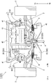
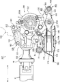
- the top view which shows the external appearance in the powertrain of a vehicle.
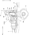
- the principal part right view which shows the principal part of the powertrain support structure in a right side view.
- the principal part bottom view which shows the principal part of the powertrain support structure in bottom view.
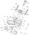
- the disassembled perspective view which shows the decomposition
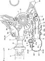
- the principal part right view which shows the principal part of the powertrain support structure in another embodiment.
- the principal part bottom view which shows the principal part of the powertrain support structure in another embodiment.
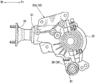
- the right view which shows the transfer in another embodiment.
- the principal part right view which shows the principal part of the powertrain support structure in a right side view.
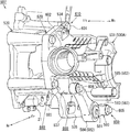
- the principal part perspective view which shows the principal part of the powertrain support structure in an assembly
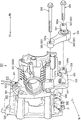
- the disassembled perspective view which shows the state which removed the intermediate bracket. Explanatory drawing explaining the cross section along the vehicle width direction in a front side fastening part and a rear side fastening part.
- FIG. 1 is an explanatory diagram for explaining the configuration of the vehicle 1
- FIG. 2 is a plan view of the appearance of the power train 7 of the vehicle 1
- FIG. 3 is a right side view of a main part of the power train support structure in a right side view.
- FIG. 4 is a bottom view of the main part of the powertrain support structure in a bottom view
- FIG. 5 is an exploded perspective view of the main part of the powertrain support structure as viewed from below the vehicle.
- arrows Fr and Rr indicate the vehicle front-rear direction
- arrow Fr indicates the vehicle front
- arrow Rr indicates the vehicle rear
- arrows Rh and Lh indicate the vehicle width direction
- arrow Rh indicates the vehicle right direction
- arrow Lh indicates the vehicle left direction.
- the upper side in FIG. 3 is the upper side of the vehicle
- the lower side in FIG. 3 is the lower side of the vehicle.
- the vehicle 1 is a so-called FF-based four-wheel drive vehicle in which a power train 7 is arranged at the front thereof.
- the power train 7 (synonymous with a power plant) outputs the output of a horizontally mounted engine 10 arranged so that a crankshaft is positioned along the vehicle width direction via a drive shaft 2. 3 and the output of the horizontally placed engine 10 is transmitted to the rear wheel 6 via the propeller shaft 4 and the rear differential 5.
- the front portion of the vehicle 1 includes a pair of left and right front side frames (not shown) extending from the dash panel (not shown) to the front of the vehicle, and a sub disposed below the front side frame.
- the horizontal engine 10 is disposed between the frame 40 and the pair of left and right front side frames and the sub frame 40 and in front of the vehicle with respect to the steering gear box 8 fixed to the rear portion of the sub frame 40.
- the power train 7 is supported by these frames 40 via a support member described later.
- the steering gear box 8 connects a steering wheel (not shown) operated by an occupant and the front wheel 3, and performs an input rotation due to the operation of the steering wheel in a substantially cylindrical main body cylinder portion 8a extending in the vehicle width direction. It functions as a steering device that changes the direction of the front wheel 3 via a gear housed in (see FIG. 4).
- the sub-frame 40 connects a pair of left and right front and rear members 41 extending in the vehicle front-rear direction, a front cross member 42 that connects the front ends of the front and rear members 41 in the vehicle width direction, and a rear end of the front and rear members 41 in the vehicle width direction. And a suspension cross member 43 to which a suspension member such as the lower arm 9 is connected, and these members 41 to 43 are integrally formed in a substantially rectangular shape in plan view.
- the suspension cross member 43 is integrally formed by joining an upper panel 44 positioned on the upper side of the vehicle and a lower panel 45 positioned on the lower side of the vehicle, overlapping each other in the vertical direction of the vehicle. Yes.
- the upper panel 44 includes a top plate portion 441 that forms the upper surface of the suspension cross member 43, and an inner rear wall portion 442 that extends downward from the rear end of the top plate portion 441 to the vehicle rear side. And an inner front wall portion 443 extending downward from the front end of the top plate portion 441 and a front edge portion 444 extending from the front end of the inner front wall portion 443 toward the front of the vehicle.
- a bolt opening hole (not shown) and a groove portion 441a are formed in this order from the front of the vehicle at approximately the center in the vehicle width direction.
- the bolt opening hole is inserted with a connecting bolt 45a for connecting a rear mount bracket 70 described later.
- the recessed groove portion 441a is disposed with the steering gear box 8 and extends in the vehicle width direction.
- the concave groove portion 441a is formed in a substantially concave groove shape in which a part of the top plate portion 441 protrudes downward in the vehicle along the main body cylinder portion 8a of the steering gear box 8.
- the recessed groove portion 441a is formed in such a size that the main body cylinder portion 8a in the steering gear box 8 can be disposed.
- the inner front wall portion 443 is provided with a bracket insertion hole 443a in which a rear mount bracket 70, which will be described later, is formed so as to be inserted into the suspension cross member 43 from the front of the vehicle.
- the lower panel 45 is opposed to the top plate portion 441 of the upper panel 44 at the lower side of the vehicle, and has a bottom plate portion 451 that contacts the front edge portion 444 and a rear end of the bottom plate portion 451 toward the upper side of the vehicle. It is integrally formed with the extended outer rear wall 452.
- the bottom plate portion 451 is formed with a bolt opening hole (not shown) through which the connecting bolt 45a is inserted at a position facing the bolt opening hole of the upper panel 44 below the vehicle.
- the power train 7 (synonymous with a power plant) drives a horizontally mounted engine 10 disposed so that a crankshaft is positioned along the vehicle width direction and the output of the horizontally mounted engine 10
- a transmission 20 that outputs to the shaft 2 and a transfer 30 that outputs the output of the transmission 20 to the propeller shaft 4 are provided.
- the horizontal engine 10 is arranged on the right side in the vehicle width direction so that the output shaft (crankshaft) is located on the left side of the vehicle.
- the transmission 20 is disposed on the left side of the vehicle with respect to the horizontal engine 10, and is fastened and fixed to the horizontal engine 10 with the input shaft positioned substantially coaxially with the output shaft of the horizontal engine 10.
- the transmission 20 switches a plurality of gears to decelerate the input rotation, and outputs the output to an output shaft arranged in parallel to the lower rear side of the vehicle with respect to the input shaft.
- the pair of left and right drive shafts 2 connected to the output shaft of the transmission 20 are arranged substantially coaxially with the output shaft of the transmission 20.
- the drive shaft 2 connected to the front wheel 3 on the right side of the vehicle is connected to the output shaft of the transmission 20 via a transfer 30 described later.
- the transfer 30 is disposed so that the input shaft is positioned substantially coaxially with the output shaft on the right side of the vehicle in the transmission 20, and is fastened and fixed to the right side of the transmission 20 with a fastening bolt 30a.
- the transfer 30 includes a transfer main body 30A and an intermediate bracket 80 attached to the lower portion of the transfer main body 30A.
- the transfer main body 30A includes a transfer case 31, a cover 32, a ring gear (not shown), a drive pinion (not shown), and a support leg 34.
- the transfer 30 (specifically, the transfer main body 30 ⁇ / b> A) includes a transfer case 31 positioned at the rear of the vehicle and a cover 32 positioned at the front of the vehicle with respect to the transfer case 31.
- the ring gear to which the input from the transmission 20 is transmitted and the drive pinion which is meshed with the ring gear and which is an output shaft are accommodated and held in an internal space constituted by
- the companion flange 33 is attached to the rear end of the drive pinion.
- the companion flange 33 is connected to the flange yoke 4 a of the propeller shaft 4.
- the transfer main body 30A has a pair of support legs extending from the transfer case 31 toward the front lower side of the vehicle and the lower side of the rear of the vehicle, as shown in FIGS. 34 is provided.
- the support legs 34 support an intermediate bracket 80 described later below the transfer case 31.
- Each support leg 34 includes a boss 35 to which the intermediate bracket 80 is attached.
- the boss portion 35 is in contact with the intermediate bracket 80 disposed substantially in the center of the vehicle 1 in the vehicle width direction, and is formed at the tip of the pair of support leg portions 34 toward the right side of the vehicle. Screw holes (not shown) into which the fastening bolts 80a for fastening the intermediate bracket 80 are screwed are formed in the boss portions 35, respectively.
- the power train 7 having the above-described configuration includes a right mount bracket 50 disposed along the vehicle width direction from the right side of the vehicle between the front side frame and the sub frame 40, and
- the left mount bracket 60, the right mount bracket 50, and the rear mount bracket 70 disposed behind the left mount bracket 60 are supported by the vehicle body, that is, the respective frames so as to be swingable.
- the right-side mounting bracket 50 connects the upper part on the right side in the vehicle width direction of the horizontally mounted engine 10 and the front side frame on the right side of the vehicle in a swingable manner.
- the right mount bracket 50 includes an engine side bracket 51 fixed to the horizontally mounted engine 10 and a vehicle body side bracket 52 fixed to the front side frame via an elastic rubber mount bush (not shown). Concatenated.
- the left mount bracket 60 slidably connects the upper left portion of the transmission 20 in the vehicle width direction and the front side frame on the left side of the vehicle.
- the left mount bracket 60 connects a transmission side bracket 61 fixed to the transmission 20 and a vehicle body side bracket 62 fixed to the front side frame via an elastic rubber mount bush (not shown). Configured.
- the rear mount bracket 70 is an intermediate bracket 80 fastened to the lower portion of the transfer body 30 ⁇ / b> A, specifically to the right side surface of the support leg 34, at the approximate center in the vehicle width direction of the vehicle 1.
- the transfer 30 and the suspension cross member 43 are connected so as to be swingable.
- the rear mount bracket 70 extends linearly in the vehicle front-rear direction, and includes a bracket front portion 71 connected to the intermediate bracket 80 and a bracket rear portion 72 connected to the suspension cross member 43. .
- the rear mount bracket 70 includes a bracket front portion 71 connected to the intermediate bracket 80 by connection bolts 70 a and nuts 70 b inserted along the vehicle width direction.
- the bracket rear portion 72 connected to the suspension cross member 43 is integrally formed in this order from the front of the vehicle by connecting bolts 45a and nuts 45b inserted along the vehicle vertical direction.
- the rear mount bracket 70 includes a bracket front portion 71 and a bracket rear portion 72 so as to be connected to the intermediate bracket 80 in front of the inner front wall portion 443 of the suspension cross member 43.
- the bracket front portion 71 faces the vehicle width direction at a predetermined interval, and also includes a pair of left and right counter plates 73 that sandwich an intermediate bracket 80 (a front mount bush 81 described later), and an upper portion of the pair of counter plates 73. And a pair of upper and lower reinforcing plates 74 that connect the lower portion and the lower portion in the vehicle width direction.
- the counter plate 73 is formed by bending a substantially rectangular metal flat plate that is long in the vehicle front-rear direction, and the counter plate main body portion 73a in which the vehicle width direction is the thickness direction, and the counter plate main body portion 73a. And a counter plate wall portion 73b extending from the vehicle vertical direction end portion toward the vehicle width direction outer side.
- the counter plate main body 73a of the counter plate 73 has a bolt insertion hole 73c through which a connection bolt 70a is inserted at the front end thereof.
- the reinforcing plate 74 is formed in a size that connects the rear end of the opposing plate wall 73b of the opposing plate 73 in the vehicle width direction.
- the bracket rear portion 72 is sandwiched between the upper panel 44 and the lower panel 45 in a state where it is connected to the suspension cross member 43 as shown in FIGS. 3 and 5.
- the bracket rear portion 72 includes a substantially cylindrical rear mount bush 75 whose axial direction is the vehicle vertical direction, and a metal bush support cylinder portion 76 into which the rear mount bush 75 is press-fitted.
- a small diameter tubular member having an inner diameter into which the connecting bolt 45a can be inserted a large diameter tubular member having a larger diameter than the small diameter tubular member, and a peripheral surface thereof face each other.
- a synthetic rubber having elasticity filled between a small-diameter tubular member and a large-diameter tubular member arranged on the same axis is included.
- the internal space in the rear mount bush 75 through which the connecting bolt 45a is inserted is referred to as a bolt insertion hole 75a.
- the bush support cylinder portion 76 is formed in a substantially cylindrical shape having an inner diameter allowing the rear mount bush 75 to be press-fitted and an axial length.
- the rear end of the bracket front portion 71 is joined to the outer peripheral surface of the bush support cylinder portion 76 by welding or the like.
- the intermediate bracket 80 includes a substantially cylindrical front mount bush 81 having an axial direction in the vehicle width direction, and an aluminum alloy bracket body 82 having a predetermined thickness.
- the peripheral surface faces a small-diameter tubular member having an inner diameter into which the connecting bolt 70a can be inserted, a large-diameter tubular member having a larger diameter than the small-diameter tubular member, and the front surface. And a synthetic rubber having elasticity filled between a small-diameter tubular member and a large-diameter tubular member arranged coaxially.
- the bracket body 82 is formed in a substantially inverted triangular shape when viewed from the side, and bolt insertion holes 82a through which fastening bolts 80a screwed into the boss portions 35 of the transfer 30 are inserted at both ends in the vehicle front-rear direction along the vehicle width direction. An opening is formed.
- the bracket body 82 is disposed so as to straddle the drive shaft 2 in the vehicle longitudinal direction.
- bracket body 82 is formed with a bush opening hole (not shown) into which the front mount bush 81 is press-fitted.
- This bush opening hole is formed in the vicinity of the position in the vehicle vertical direction where the lower end of the transmission 20 and the transfer 30 overlap in the vehicle width direction in the vicinity of the position in the vehicle longitudinal direction substantially the same as the position of the drive shaft 2 in the vehicle longitudinal direction. Has been.
- connection position between the transfer 30 and the rear mount bracket 70 is the position of the drive shaft 2 in the vehicle front-rear direction, and in the vicinity of the lower end of the transmission 20 below the drive shaft 2.
- the intermediate bracket 80 is configured so that the vehicle 30 and the transfer 30 overlap each other in the vehicle width direction.
- the rear mount is such that the transfer position of the transfer 30 and the rear mount bracket 70 with respect to the vehicle body is located in front of the inner front wall 443 of the suspension cross member 43 and below the drive shaft 2.
- a bracket 70 and an intermediate bracket 80 are configured.
- the intermediate bracket 80 is configured such that the vicinity of the lower end of the positioned power train 7 is a connection position of the rear mount bracket 70 to the transfer 30.
- TM side imaginary line that extends downward from the output shaft of the transmission 20 and a vehicle body side imaginary line that extends forward from the virtual midpoint in the axial direction of the rear mount bush 75 connected to the suspension cross member 43.
- the rear mount bracket 70 and the intermediate bracket 80 are configured so that the position of the intersection with the vehicle is the connection position of the transfer 30 and the rear mount bracket 70 with respect to the vehicle body.
- the powertrain support structure of the vehicle 1 that supports the powertrain 7 with the above-described configuration suppresses the influence on the vehicle interior even when the vehicle 1 equipped with the transverse engine 10 includes the transfer 30. can do.
- the rear mount bracket 70 is connected to the transfer 30 below the drive shaft 2, so that the powertrain support structure of the vehicle 1 places the position of the rear mount bracket 70 relative to the vehicle body on the vehicle front side. be able to.
- the powertrain support structure of the vehicle 1 has a rear mount bracket for the vehicle body.
- the position 70 can be easily arranged on the vehicle lower side.
- the bracket rear portion 72 of the rear mount bracket 70 is connected to the suspension cross member 43 disposed below the rear end of the transfer 30, so that the powertrain support structure of the vehicle 1 is substantially the same as the suspension cross member 43.
- the rear mount bracket 70 can be disposed at a position in the vehicle vertical direction at a position ahead of the vehicle relative to the suspension cross member 43.
- the powertrain support structure of the vehicle 1 can lower the mounting position of the powertrain 7 on the vehicle body to the vehicle lower side.
- the powertrain support structure of the vehicle 1 includes the connection position between the rear mount bracket and the transmission 20 in the front wheel drive vehicle, and the rear position in the four wheel drive vehicle.
- the connecting position of the mount bracket 70 and the transfer 30 can be easily made substantially the same position.
- the powertrain support structure of the vehicle 1 can make the total height of the front-wheel drive vehicle and the total height of the four-wheel drive vehicle substantially the same in a vehicle type in which front-wheel drive and four-wheel drive are set, for example.
- the power train support structure of the vehicle 1 can suppress the floor panel and the dash panel from bulging out to the vehicle interior side.
- the powertrain support structure of the vehicle 1 can be arranged on the vehicle lower side with respect to the conventional mounting position of the powertrain 7, so that the rear mount bracket 70 is arranged on the vehicle vertical direction lower side than the propeller shaft 4.
- the propeller shaft 4 itself can be disposed below the conventional one, thereby suppressing an increase in the size of the floor tunnel through which the propeller shaft 4 is inserted.
- the powertrain support structure of the vehicle 1 can lower the mounting position of the powertrain 7 with respect to the vehicle body to the lower side of the vehicle, and can suppress the influence on the vehicle interior even when the transfer 30 is provided. .
- bracket rear portion 72 has a bolt insertion hole 75a through which the connecting bolt 45a is inserted from the vehicle vertical direction, and is provided with a rear mount bush 75 having elasticity, so that the powertrain support structure of the vehicle 1 is attached to the vehicle body. Even if the mounting position of the powertrain 7 is lowered, interference with the vehicle body can be suppressed.
- the length of the rear mount bracket in the vertical direction of the vehicle tends to be long due to the outer diameter of the rear mount bush. For this reason, when the height of the member side bracket is increased and the mounting position of the power train 7 on the vehicle body is lowered, the transfer 30 and the propeller shaft 4 may interfere with the member side bracket.
- the powertrain support structure of the vehicle 1 has the length of the rear mount bracket 70 in the vehicle vertical direction. The length can be suppressed short.
- the rear mount bracket 70 that inserts the connecting bolt 45a into the rear mount bush 75 from the vehicle vertical direction can suppress the length in the vehicle vertical direction to be shorter than when the connecting bolt is inserted from the vehicle width direction. it can.
- the powertrain support structure of the vehicle 1 can suppress the thickness of the suspension cross member 43 to which the bracket rear portion 72 of the rear mount bracket 70 is coupled as compared with the case where the coupling bolt 45a is inserted from the vehicle width direction. it can.
- the powertrain support structure of the vehicle 1 is such that the transfer 30 and the propeller shaft 4 are not mounted on the vehicle body even when the mounting position of the powertrain 7 on the vehicle body is lowered by the rear mount bush 75 through which the connecting bolt 45a is inserted from the vehicle vertical direction. Interference with the side, for example, the floor panel can be prevented.
- the concave groove portion 441a is formed in the suspension cross member 43, and the steering gear box 8 is disposed in the concave groove portion 441a of the suspension cross member 43, so that the power train support structure of the vehicle 1 has a power to the vehicle body.
- the mounting position of the train 7 can be lowered further below the vehicle.
- the steering gear box 8 is often arranged behind the power train 7. For this reason, if the mounting position of the power train 7 on the vehicle body is lowered, for example, the rear end of the transfer 30 or the propeller shaft 4 may interfere with the steering gear box 8.
- the steering gear box 8 is disposed in the recessed groove portion 441a formed in the suspension cross member 43, so that the powertrain support structure of the vehicle 1 lowers the mounting position of the steering gear box 8 with respect to the vehicle body downward. be able to. That is, the powertrain support structure of the vehicle 1 can lower the mounting position of the powertrain 7 relative to the vehicle body further downward without interference between the powertrain 7 and the steering gear box 8.
- the powertrain support structure of the vehicle 1 has substantially the same mounting position of the steering gear box 8 with respect to the vehicle body between the front-wheel drive vehicle and the four-wheel drive vehicle. Can be in position.
- the powertrain 7 support structure of the vehicle 1 can further suppress the difference in the mounting position of the powertrain 7 with respect to the vehicle body between the front-wheel drive vehicle and the four-wheel drive vehicle, and can increase the ratio of common parts.
- the mounting position of the powertrain 7 on the vehicle body and the mounting position of the steering gear box 8 are substantially the same in the front-wheel drive vehicle and the four-wheel drive vehicle.
- the powertrain support structure of the vehicle 1 can share the geometry of the undercarriage between the front wheel drive vehicle and the four wheel drive vehicle, for example.
- the power train support structure of the vehicle 1 can lower the mounting position of the power train 7 relative to the vehicle body to the lower side of the vehicle by arranging the steering gear box 8 in the concave groove portion 441a of the suspension cross member 43.
- the design of the vehicle 1 in a vehicle type in which front wheel drive and four wheel drive are set can be facilitated.
- bracket front portion 71 and the transfer 30 are connected to each other via the intermediate bracket 80, and the front bracket bush 81 is provided in the intermediate bracket 80, so that the powertrain support structure of the vehicle 1 can be transferred.
- the front mount bush 81 can be easily interposed without separately forming the case 31 (transfer body 30A).
- the size of the front mount bush 81 may be different for each vehicle type, and therefore the front mount bush 81 is provided integrally with the transfer 30. It is necessary to make a transfer case 31 for each vehicle type.
- the intermediate bracket 80 is provided, and the intermediate bracket 80 is provided with the front mount bush 81, so that the powertrain support structure of the vehicle 1 is suitable for each vehicle type without making the transfer case 31 separately. Further, the transfer 30 and the rear mount bracket 70 can be connected via the front mount bush 81.
- the transfer 30 and the rear mount bracket 70 are connected via the intermediate bracket 80, and therefore the front mount bush 81 can be easily interposed without separately forming the transfer case 31. be able to.
- the vehicle includes a right mount bracket 50 that elastically supports the horizontally mounted engine 10 and a left mount bracket 60 that elastically supports the transmission 20 so that the transmission 20 can swing, and the rear mount bracket 70 is arranged in the vehicle width direction of the vehicle body.
- the right mount bracket 50 and the left mount bracket 60 are arranged substantially at the center, and are configured to suspend the power train 7 at a position in front of the vehicle and above the vehicle with respect to the bracket front portion 71.
- the power train support structure of the vehicle 1 can support the power train 7 that is a heavy object in a well-balanced manner and can suppress the influence on the vehicle interior.
- the center of gravity position of the power train 7 of the front wheel drive vehicle and the center of gravity position of the power train 7 of the four wheel drive vehicle are It will be different from the difference.
- the rear mount bracket 70 when the rear mount bracket 70 is arranged in accordance with the position of the center of gravity, the position of the rear mount bracket 70 in the vehicle width direction is different between the front wheel drive vehicle and the four wheel drive vehicle.
- the powertrain support structure of the vehicle 1 has the powertrain 7 of the front-wheel drive vehicle and the powertrain 7 of the four-wheel drive vehicle at substantially the same position. Can be supported.
- the powertrain support structure of the vehicle 1 supports the powertrain 7 in a well-balanced manner. can do.
- the power train support structure of the vehicle 1 balances the power train 7 that is a heavy object by the power train 7 being supported by the right mount bracket 50, the left mount bracket 60, and the rear mount bracket 70 so as to be swingable. While supporting well, the influence on a vehicle interior can be suppressed.
- the rear mount bracket 70 is configured by the bracket front portion 71 and the bracket rear portion 72 provided with the rear mount bush 75.
- the present invention is not limited to this.
- the bracket front portion, and A torque rod having a mount bush at the rear of the bracket may be used.
- the bracket rear portion 72 of the rear mount bracket 70 is configured to be directly connected to the suspension cross member 43.
- the present invention is not limited to this.
- the bracket rear portion 72 is connected to the suspension cross member 43 via a vehicle body side bracket. It may be configured to.
- front mount bush 81 and the rear mount bush 75 filled with synthetic rubber are used, the present invention is not limited to this, and a liquid seal mount bush or the like may be used.
- the front part of the rear mount bracket of the present invention corresponds to the bracket front part 71 of the embodiment
- the rear part of the rear mount bracket corresponds to the bracket rear part 72
- the cross member corresponds to the suspension cross member 43
- the groove portion corresponds to the groove portion 441a
- the engine side mounting bracket corresponds to the right side mounting bracket 50
- the mission side mounting bracket corresponds to the left side mounting bracket 60
- the present invention is not limited only to the configuration of the above-described embodiment, and many embodiments can be obtained.
- the intermediate bracket 80 may be omitted, and the bush press-fit portion 36 to which the rear mount bracket 70 is connected may be integrally formed with the transfer case 31.
- the power train support structure according to the first embodiment is shown in FIG. 6 showing a right side view of the main part, FIG. 7 showing a bottom view of the main part of the power train support structure, and a right side view of the transfer 30.
- a front mount bush 81 is press-fitted into a bush press-fit portion 36 that extends downward from the lower portion of the transfer case 31 toward the front of the vehicle.
- the transfer 30 includes a transfer main body 30A and a bush press-fit portion 36 that is integrally provided at the lower portion of the transfer main body 30A and into which the front mount bush 81 is press-fitted.
- the bush press-fit portion 36 may be connected to the rear mount bracket 70 via the front mount bush 81.
- the rear mount bracket 70 may be connected to the transfer 30, particularly the front mount bush 81 provided integrally with the transfer main body 30 ⁇ / b> A without using the intermediate bracket 80.
- the bush press-fit portion 36 is formed so that the connection position between the front mount bush 81 of the transfer 30 and the rear mount bracket 70 is equivalent to the above-described embodiment.
- the power train support structure of the vehicle 1 is the case where the transfer 30 is provided in the vehicle 1 in which the transverse engine 10 is mounted, as in the first embodiment described above.
- the influence on the passenger compartment can be suppressed.
- the powertrain support structure of the vehicle 1 suppresses an increase in the number of parts, and via the front mount bush 81.
- the rear mount bracket 70 and the transfer 30 can be connected.
- FIG. 1 the powertrain support structure of the vehicle 1 in this embodiment will be described in detail with reference to FIGS. 1, 2, and 9 to 12.
- FIG. 1 the powertrain support structure of the vehicle 1 in this embodiment will be described in detail with reference to FIGS. 1, 2, and 9 to 12.
- the powertrain support structure of the vehicle 1 in the second embodiment is devised so that the fastening bolts can be prevented from loosening and the rear mount bracket can be supported stably.
- the contact surface of the transfer and the rear mount bracket may slightly slide, which may cause loosening of the fastening bolt that fastens the transfer and the rear mount bracket.
- the second embodiment is also intended to provide a vehicle powertrain support structure that can stably support the rear mount bracket by suppressing the looseness of the fastening bolt.
- FIG. 1 and FIG. 2 show a right side view of the main part of the powertrain support structure in the right side view
- FIG. 10 shows a perspective view of the main part of the powertrain support structure in the assembled state
- FIG. 11 shows a state in which the intermediate bracket 580 is removed.
- FIG. 12 shows an exploded perspective view
- FIG. 12 shows an explanatory view for explaining a cross section along the vehicle width direction in the front side fastening portion 650 and the rear side fastening portion 660.
- FIG. 12A in FIG. 12 shows a cross-sectional view of the front side fastening portion 650
- FIG. 12B shows a cross-sectional view of the rear side fastening portion 660.
- the vehicle 501 is a so-called FF-based four-wheel drive vehicle in which the power train 7 is disposed in the front part thereof.
- this power train 507 (synonymous with a power plant) outputs the output of a horizontally mounted engine 10 arranged so that the crankshaft is positioned along the vehicle width direction via the drive shaft 2. 3 and the output of the horizontally placed engine 10 is transmitted to the rear wheel 6 via the propeller shaft 4 and the rear differential 5.
- the arrangement of the power train 7 and the specific configuration of the steering gear box 8 are the same as those in the first embodiment.
- the sub frame 40 has the same basic configuration as that of the first embodiment except for the specific configuration of the suspension cross member 43. That is, the subframe 40 includes a pair of left and right front and rear members 41, a front cross member 42, and a suspension cross member 543.
- the suspension cross member 543 in the second embodiment has an upper panel 544 positioned on the upper side of the vehicle and a lower panel 545 positioned on the lower side of the vehicle, as shown in FIG. They are integrally formed by overlapping and joining in the direction.
- the upper panel 544 has a cross section along the vehicle front-rear direction formed in a cross-sectional hat shape in which the vehicle lower portion is opened.
- a bolt opening hole (not shown) through which a connection bolt 545a for connecting a rear mount bracket 570 to be described later is inserted is formed in the vehicle vertical direction at substantially the center in the vehicle width direction of the vehicle 501.
- the front surface of the upper panel 544 is provided with a bracket insertion hole 546 in which a rear mount bracket 570, which will be described later, is formed so as to be open from the front of the vehicle.
- the lower panel 545 has a substantially flat cross section along the vehicle longitudinal direction.
- the lower panel 545 is formed with a bolt opening hole (not shown) through which the connection bolt 545a is inserted so as to face the bolt opening hole of the upper panel 544 in the vehicle vertical direction, and the connection bolt 545a is screwed.
- a weld nut 545b is welded.
- the power train 507 includes a right mount bracket 50 disposed along the vehicle width direction from the right side of the vehicle in a space surrounded by the pair of left and right front side frames and the sub frame 40. And a left mount bracket 60, a right mount bracket 50, and a rear mount bracket 570 disposed behind the left mount bracket 60 so as to be swingable on the vehicle body side.
- the rear mount bracket 570 connects the rear portion of the power train 507 (an intermediate bracket 580 described later) and the suspension cross member 543 so as to be capable of swinging at approximately the center in the vehicle width direction of the vehicle 501. Yes.
- the rear mount bracket 570 includes a bracket front portion 571 that is swingably connected to the rear portion of the power train 507 by a connecting bolt 570a, and a bracket that is swingably connected to the suspension cross member 543 by a connecting bolt 545a.
- the rear portion 572 is integrally formed by joining in this order from the front of the vehicle.
- the bracket front portion 571 is configured by arranging substantially flat metal plates having a thickness in the vehicle width direction so as to face each other at a predetermined interval in the vehicle width direction. Furthermore, a bolt insertion hole (not shown) through which the connecting bolt 570a is inserted is formed in the metal flat plate on the right side of the vehicle in the bracket front portion 571. On the other hand, a weld nut (not shown) to which the connecting bolt 570a is screwed is welded to the metal flat plate on the left side of the vehicle in the bracket front portion 571.
- the bracket rear portion 572 is configured by press-fitting an elastic mount bush into a metal tubular member whose axial direction is the vehicle vertical direction. As shown in FIG. 9, the bracket rear portion 572 is connected to the suspension cross member 543 by using connection bolts 545a so as to be sandwiched between the upper panel 544 and the lower panel 545.
- the power train 507 supported on the vehicle body in this manner includes a horizontally placed engine 10 disposed so that the crankshaft is positioned along the vehicle width direction, A transmission 520 that outputs the output of the engine 10 to the drive shaft 2 and a transfer 530 that outputs the output of the transmission 520 to the propeller shaft 4 are provided.
- the horizontal engine 10 is arranged on the right side in the vehicle width direction so that the output shaft (crankshaft) is located on the left side of the vehicle, as shown in FIG. *
- the transmission 520 is arranged on the left side of the vehicle with respect to the horizontal engine 10 and is fastened and fixed to the horizontal engine 10 so that the input shaft is positioned substantially coaxially with the output shaft of the horizontal engine 10. .
- the transmission 520 switches a plurality of gears to decelerate the input rotation, and outputs it to an output shaft arranged in parallel to the vehicle rear lower side with respect to the input shaft.
- the transmission 520 is formed with a boss portion (not shown) to which a fastening bolt for fastening the transfer 530 is screwed toward the right side of the vehicle. Further, as shown in FIGS. 10 and 11, the transmission 520 communicates with a rear bracket insertion hole 585 a of an intermediate bracket 580 described later and a screw to which a rear fastening bolt 606 is screwed in a state where the transfer 530 is assembled.
- a boss portion 21 having a hole 21a is formed toward the right side of the vehicle.
- the pair of left and right drive shafts 2 connected to the output shaft of the transmission 520 are disposed substantially coaxially with respect to the output shaft of the transmission 520.
- the drive shaft 2 connected to the front wheel 3 on the right side of the vehicle is connected to the output shaft of the transmission 520 via the transfer 530.
- the transfer 530 is arranged so that the input shaft is positioned substantially coaxially with the output shaft on the right side of the vehicle in the transmission 520.
- the transfer 530 has a function of outputting the input transmitted from the transmission 520 to an output shaft that is substantially orthogonal to the input shaft.
- the transfer 530 includes a transfer main body 530A and an intermediate bracket 580 attached to the lower part of the transfer main body 530A.
- the transfer main body 530A includes a transfer case 531, a cover 532, a ring gear (not shown), a drive pinion (not shown), an upper mounting base 534, and a lower mounting base 535. *
- the transfer 530 (specifically, the transfer main body 530A) includes a transfer case 531 located at the rear of the vehicle and a cover 532 located at the front of the vehicle.
- the cover 532 is configured to be hollow inside.
- This transfer body 530A has a ring gear rotatably supported with the vehicle width direction as a rotation axis and a drive pinion gear meshing with the ring gear at the front end, and is rotatably supported with the vehicle longitudinal direction as the rotation axis. And a drive pinion which is an output shaft.
- a companion flange 33 to which the flange yoke 4a of the propeller shaft 4 is connected is attached to the rear end of the drive pinion.
- the transfer 530 having such a configuration is fastened and fixed to the right side surface of the transmission 520 using a plurality of fastening bolts, as shown in FIGS. 9 to 11. *
- the left side of the transfer case 531 includes a substantially flat upper attachment base 534 extending upward and a substantially flat lower attachment base 535 extending downward of the vehicle. ing.
- the upper mounting base 534 is formed in a shape that projects upward in the vehicle longitudinal direction from the vicinity of the rear end of the transfer case 531 to the front end in the vehicle side view. .
- a bolt hole (not shown) through which the first fastening bolt 601 screwed into the transmission 520 is inserted is formed in the vicinity of the front end.
- a fastening portion between the transmission 520 and the transfer 530 (specifically, the transfer main body 530A) fastened using the first fastening bolt 601 is defined as a first fastening portion 610.
- a bolt hole (not shown) through which the second fastening bolt 602 screwed into the transmission 520 is inserted is formed in the upper mounting base 534 in the vicinity of the rear end.
- a fastening portion between the transmission 520 and the transfer 530 (specifically, the transfer main body 530A) fastened using the second fastening bolt 602 is a second fastening portion 620.
- the lower mounting base 535 is formed in a shape such that its rear end is located in the vicinity of the rear end of the transfer case 531, and its front end protrudes below the front end of the transfer case 531 toward the front of the vehicle. ing.
- the lower mounting base 535 is formed with a bolt hole (not shown) through which the third fastening bolt 603 screwed into the transmission 520 is inserted in the vicinity of the front end.
- a fastening portion between the transmission 520 and the transfer 530 (specifically, the transfer main body 530A) fastened using the third fastening bolt 603 is referred to as a third fastening portion 630.
- a bolt hole (not shown) through which the fourth fastening bolt 604 threadedly engaged with the transmission 520 is inserted is formed in the lower mounting base 535 in the vicinity of the rear end.
- a fastening portion between the transmission 520 and the transfer 530 (specifically, the transfer main body 530A) fastened using the fourth fastening bolt 604 is referred to as a fourth fastening portion 640.
- the transfer 530 particularly the lower mounting base 535 of the transfer body 530 ⁇ / b> A, includes a front bracket mounting portion 536 and a rear bracket mounting portion 537 to which an intermediate bracket 580 described later is mounted. Is formed.
- the front bracket mounting portion 536 is integrally formed with the lower mounting base 535 so as to be erected toward the right side of the vehicle on the vehicle front side of the third fastening portion 630.
- the front bracket mounting portion 536 has a flat surface that comes into contact with the intermediate bracket 580 on the right side of the vehicle, and a screw hole 536a into which the front fastening bolt 605 is screwed has a vehicle width direction. It is formed along.
- the rear bracket mounting portion 537 is a vehicle between the third fastening portion 630 and the fourth fastening portion 640, at the upper portion of the lower mounting base portion 535, from the vicinity of the fourth fastening portion 640.
- the lower mounting base 535 is integrally formed so as to stand upright. That is, the rear bracket mounting portion 537 is formed in the transfer case 531 in the vicinity of the output shaft to which the propeller shaft 4 is connected.
- the rear bracket mounting portion 537 is formed such that the left side of the vehicle contacts the boss portion 21 of the transmission 520 and the right side of the vehicle contacts the intermediate bracket 580.
- the rear bracket mounting portion 537 is formed with a transfer insertion hole 537a that communicates with the screw hole 21a of the boss portion 21 in the transmission 520 in the vehicle width direction and through which the rear fastening bolt 606 is inserted.
- the intermediate bracket 580 includes a substantially cylindrical mounting bush 581 having an axial direction in the vehicle width direction and an aluminum alloy bracket body 582 having a predetermined thickness in the vehicle width direction. Prepare.
- the mount bush 581 is coaxial so that the small diameter tubular member having an inner diameter into which the connecting bolt 570a can be inserted, the large diameter tubular member having a larger diameter than the small diameter tubular member, and the peripheral surface face each other. And a synthetic rubber having elasticity filled between the small-diameter tubular member and the large-diameter tubular member arranged above.
- the bracket body 582 has a substantially cylindrical front end portion 583, a central portion 584, and a rear end portion 585 extending in the vehicle width direction in this order from the front of the vehicle, and the front end portion 583, the central portion 584, and the center.
- the part 584 and the rear end part 585 are connected and integrally formed in a substantially V shape in side view.
- the front end 583 has a front bracket insertion hole 583a through which the front fastening bolt 605 is inserted and communicated with the screw hole 536a of the front bracket mounting portion 536 in the transfer 530. It is formed into a shape.
- the front end portion 583 of the intermediate bracket 580 is fastened and fixed to the front bracket mounting portion 536 of the transfer 530 (specifically, the transfer main body 530A) in a state where the transfer 530 is fastened to the transmission 520.
- this fastening location be the front side fastening part 650 (refer FIG.9 and FIG.10).
- the central portion 584 has a larger diameter than the outer diameter of the front end portion 583 and is formed in a substantially cylindrical shape having an inner diameter that allows the mounting bush 581 to be press-fitted.
- the central portion 584 is disposed below the drive shaft 2 and in the vicinity of the position in the vehicle vertical direction where the vicinity of the lower end of the transmission 520 and the transfer 530 overlap in the vehicle width direction.
- the central portion 584 is a vehicle in which the vicinity of the lower end of the transmission 520 and the transfer 530 (transfer body 530A) overlap in the vehicle width direction in the vicinity of the position in the vehicle front-rear direction substantially the same as the position of the drive shaft 2 in the vehicle front-rear direction. It is provided in the vicinity of the vertical position.
- connection position between the transfer 530 and the rear mount bracket 570 is the position of the drive shaft 2 in the vehicle front-rear direction and near the lower end of the transmission 520 below the drive shaft 2.
- the intermediate bracket 580 is configured so that the vehicle 30 and the transfer 30 overlap with each other in the vehicle width direction.
- the rear mount bracket 570 and the intermediate bracket are connected so that the transfer position of the transfer 530 and the rear mount bracket 70 is located in front of the suspension cross member 543 and below the drive shaft 2. 580 is configured.
- the rear end portion 585 is inserted with a rear fastening bolt 606 at a position above the center portion 584 and behind the rear bracket mounting portion 537 in the transfer 530.
- the transfer insertion hole 537 a and the rear bracket insertion hole 585 a communicating with the screw hole 21 a of the boss portion 21 in the transmission 520 are formed.
- the rear end portion 585 of the intermediate bracket 580 is fastened and fixed to the boss portion 21 of the transmission 520 with the rear bracket mounting portion 537 of the transfer 530 sandwiched in a state where the transfer 530 is fastened to the transmission 520.
- the power train support structure of the vehicle 501 includes the transmission 520, the transfer 530, And the rear side fastening part 660 (refer FIG.9 and FIG.10) which fastens the intermediate bracket 580 together is comprised.
- the powertrain support structure of the vehicle 501 that realizes the above configuration is similar to the first embodiment even if the vehicle 501 equipped with the horizontally mounted engine 10 includes the transfer 530. The influence on the room can be suppressed.
- the powertrain support structure of the vehicle 501 in the second embodiment can stably support the rear mount bracket 570 by suppressing the looseness of the rear fastening bolt 606.
- the transfer 530 and the rear mount bracket 570 are connected via the intermediate bracket 580, so that the powertrain support structure of the vehicle 501 is suitable for each vehicle type without forming the transfer case 531 separately.
- 530 and the rear mount bracket 570 can be connected.
- the transmission 520, the transfer 530, and the intermediate bracket 580 are fastened together by the rear side fastening portion 660, the power train support structure of the vehicle 501 swings the power train 507 due to road surface unevenness or the like. At this time, the load acting on the intermediate bracket 580 can be transmitted to the transmission 520 via the rear fastening bolt 606.
- the powertrain support structure of the vehicle 501 can suppress, for example, slight sliding on the contact surface between the transfer 530 and the intermediate bracket 580, and can suppress loosening of the rear fastening bolt 606.
- the power train support structure of the vehicle 501 can reduce the load acting on the transfer 530, the transfer 530 can be prevented from being damaged.
- the power train support structure of the vehicle 501 includes the rear side fastening portion 660 that integrally fastens the transmission 520, the transfer 530, and the intermediate bracket 580, thereby suppressing the looseness of the rear fastening bolt 606, and
- the mount bracket 570 can be stably supported.
- the rear side fastening portion 660 is disposed between the third fastening portion 630 and the fourth fastening portion 640 that are adjacent to each other in a side view of the vehicle, so that the powertrain support structure of the vehicle 501 is configured with the rear fastening bolt 606. The loosening can be further suppressed, and a stable support state of the rear mount bracket 570 can be secured.
- the rear side fastening portion 660 is disposed between the adjacent third fastening portion 630 and the fourth fastening portion 640, so that the powertrain support structure of the vehicle 501 has rigidity in the vicinity of the boss portion 21 of the transmission 520. Can be improved.
- the powertrain support structure of the vehicle 501 can improve the support rigidity of the intermediate bracket 580 in the fastened state. For this reason, the powertrain support structure of the vehicle 501 can further suppress the loosening of the rear fastening bolt 606.
- the powertrain support structure of the vehicle 501 more reliably loosens the rear fastening bolt 606 by arranging the rear fastening portion 660 between the adjacent third fastening portion 630 and the fourth fastening portion 640. Since it can suppress, the stable support state of the rear mount bracket 570 can be ensured.
- the powertrain support structure of the vehicle 501 makes the rear fastening bolt 606 loose.
- gear noise transmitted to the vehicle body via the rear mount bracket 570 can be reduced.
- the transfer 530 outputs the output of the transmission 520 to the propeller shaft 4 connected to the drive pinion via the ring gear and the drive pinion gear.
- the powertrain support structure of the vehicle 501 can be transmitted to the vehicle body via the transfer case 531 and the rear mount bracket 570, the transfer case 531, and the rear fastening.
- Gear noise can be distributed and transmitted to a transmission path that is transmitted to the transmission 520 via the bolt 606.
- the powertrain support structure of the vehicle 501 can reduce gear noise transmitted from the vehicle body to the vehicle interior via the rear mount bracket 570, and can reduce discomfort given to the occupant.
- the powertrain support structure of the vehicle 501 is configured such that the rear side fastening portion 660 is disposed in the vicinity of the output shaft of the transfer 530, thereby suppressing the loosening of the rear fastening bolt 606 and the vehicle body via the rear mount bracket 570.
- the transmitted gear noise can be reduced.
- the intermediate bracket 580 having the mount bush 581 is used.
- the present invention is not limited to this, and the intermediate bracket 580 having no mount bush may be used.
- the bracket front portion 571 of the rear mount bracket 570 may be provided with a mount bush having elasticity.
- the rear mount bracket 570 is connected to the suspension cross member 543.
- the present invention is not limited to this, and the rear mount bracket 570 may be connected to a reinforcing member such as a frame member such as a frame or a cross member that reinforces the frame member. .
- the transfer 530 (transfer body 530A) and the intermediate bracket 580 are fastened at two locations using the front fastening bolt 605 and the rear fastening bolt 606, but the present invention is not limited to this, and the transfer 530 (transfer body 530A)
- the intermediate bracket 580 may be configured to be fastened at three or more locations.
- the present invention is not limited to this. It is good also as a structure co-tightened in more than the location.
- the front fastening bolt 605 is screwed into the boss portion of the transmission 520, and the transmission side 520, the transfer 530 (transfer body 530A), and the middle between the front side fastening portion 650 and the rear side fastening portion 660.
- the bracket 580 may be configured to be fastened together.
- the third fastening part 630 is arranged between the front fastening part 650 and the rear fastening part 660.
- the powertrain support structure of the vehicle 501 can more reliably suppress loosening of the front fastening bolt 605 and the rear fastening bolt 606, and can secure a more stable fastening state between the transmission 520 and the transfer 530. .
- the powertrain support structure of the vehicle 501 applies loads acting on the intermediate bracket 580 to the front fastening bolt 605 and the rear fastening bolt 606. Can be distributed and transmitted to the transmission 520.
- the powertrain support structure of the vehicle 501 can more reliably suppress loosening of the front fastening bolt 605 and the rear fastening bolt 606 and more reliably prevent the transfer 530 from being damaged.
- the load acting on the intermediate bracket 580 is distributed and transmitted to the transmission 520 via the front fastening bolt 605 and the rear fastening bolt 606, whereby the powertrain support structure of the vehicle 501 has the transfer 530 and the third The load transmitted to the transmission 520 through the fastening portion 630 can be reduced. For this reason, the powertrain support structure of the vehicle 501 can suppress loosening of the third fastening bolt 603 in the third fastening portion 630 and the like.
- the power train support structure of the vehicle 501 includes the front fastening portion 650 and the rear fastening portion 660 to which the transmission 520, the transfer 530 (transfer body 530A), and the intermediate bracket 580 are fastened together, and the front fastening portion 650. Since the third fastening portion 630 is disposed between the rear fastening bolt 660 and the rear fastening bolt 660, loosening of the front fastening bolt 605 and the rear fastening bolt 606 is more reliably suppressed, and more stable transmission 520 and transfer 530 are achieved. It is possible to secure the fastening state.
- the vehicle body of the present invention corresponds to the suspension cross member 543 of the embodiment
- the front part of the rear mount bracket corresponds to the bracket front part 571
- the fastening bolt corresponds to the rear fastening bolt 606
- the bracket insertion hole corresponds to the rear bracket insertion hole 585a
- the joint fastening portion corresponds to the rear fastening portion 660
- the fastening portions correspond to the first fastening portion 610, the second fastening portion 620, the third fastening portion 630, and the fourth fastening portion 640
- the adjacent fastening portions correspond to the third fastening portion 630 and the fourth fastening portion 640
- Adjacent joint fastening parts correspond to the front fastening part 650 and the rear fastening part 660
- the present invention is not limited only to the configuration of the above-described embodiment, and many embodiments can be obtained.
- the output of the transmission is transmitted via a transverse engine whose rotational axis is positioned in the vehicle width direction of the vehicle, a transmission that transmits the output of the lateral engine to a front wheel via a drive shaft, and a propeller shaft.
- a powertrain support structure for a vehicle comprising a powertrain including a transfer for transmitting to a rear wheel, a rear portion of the powertrain, and a rear mount bracket for elastically supporting the powertrain so as to be swingable.
- the front portion of the rear mount bracket is connected to the transfer at a position below the drive shaft and in a vehicle vertical direction where the transmission and the transfer overlap in the vehicle width direction.
- the dead space below the drive shaft can be effectively used to suppress the influence on the vehicle interior.
- the powertrain support structure of the vehicle can place the position of the rear mount bracket relative to the vehicle body on the front side of the vehicle.
- the front portion of the rear mount bracket is connected to the transfer, so that the vehicle powertrain support structure The position can be easily arranged on the vehicle lower side.
- the powertrain support structure of the vehicle allows the powertrain support structure of the vehicle to lower the powertrain mounting position relative to the vehicle body to the vehicle lower side. For this reason, for example, in a vehicle type in which front-wheel drive and four-wheel drive are set, the powertrain support structure of the vehicle includes a connection position between the rear mount bracket and the transmission in the front wheel drive vehicle, and a rear mount bracket in the four wheel drive vehicle. And the transfer position can be easily arranged at substantially the same position.
- the total height of the front wheel drive vehicle and the total height of the four wheel drive vehicle can be made substantially the same.
- the vehicle power train support structure suppresses the bulging of the floor panel and the dash panel to the vehicle interior side, and the floor through which the propeller shaft is inserted. The enlargement of the tunnel can be suppressed.
- the powertrain support structure of the vehicle can lower the position where the powertrain is mounted on the vehicle body to the lower side of the vehicle, and can suppress the influence on the vehicle interior even when a transfer is provided.
- the rear mount bracket has a rear part mounting bush having a bolt insertion hole through which a connecting bolt that is screwed to the vehicle body is inserted along the vehicle vertical direction, and having elasticity. it can.
- the powertrain support structure of the vehicle can suppress interference with the vehicle body side even when the mounting position of the powertrain with respect to the vehicle body is lowered.
- the length of the rear mount bracket in the vertical direction of the vehicle tends to be long due to the outer diameter of the rear mount bush. For this reason, if the height of the member side bracket is increased and the mounting position of the power train on the vehicle body is lowered, the transfer and the propeller shaft may interfere with the member side bracket.
- the vehicle powertrain support structure reduces the length of the rear mount bracket in the vehicle vertical direction. be able to.
- the axial length tends to be shorter than the radial length of the rear mount bush.
- the rear mount bracket that inserts the connecting bolt into the rear mount bush from the vehicle vertical direction can suppress the length in the vehicle vertical direction to be shorter than when the connecting bolt is inserted from the vehicle width direction.
- the powertrain support structure of the vehicle is such that even if the mounting position of the powertrain with respect to the vehicle body is lowered by the rear mounting bush through which the connecting bolt is inserted from the vehicle vertical direction, the transfer, the propeller shaft, etc. interfere with the vehicle body side. Can be prevented.
- a cross member extending in the vehicle width direction behind the drive shaft and below the propeller shaft is coupled to the front wheel so as to be steerable, and the cross member A steering gear box fixed to the vehicle, wherein the cross member includes a concave groove portion extending in the vehicle width direction and recessed at the vehicle lower side, and the steering gear box includes the concave groove portion of the cross member. It may be arranged in.
- the powertrain support structure of the vehicle can lower the powertrain mounting position relative to the vehicle body to the lower side of the vehicle.
- the steering gear box is often arranged behind the power train. For this reason, when the mounting position of the power train on the vehicle body is lowered, for example, the rear end of the transfer or the propeller shaft may interfere with the steering gear box.
- the vehicle powertrain support structure can lower the mounting position of the steering gear box with respect to the vehicle body downward.
- the powertrain support structure of the vehicle can lower the powertrain mounting position relative to the vehicle body to the lower side of the vehicle without interference between the powertrain and the steering gear box.
- the powertrain support structure of the vehicle ensures that the mounting position of the steering gear box with respect to the vehicle body is substantially the same for the front wheel drive vehicle and the four wheel drive vehicle. can do.
- the powertrain support structure of the vehicle can further suppress the difference in the mounting position of the powertrain with respect to the vehicle body between the front wheel drive vehicle and the four wheel drive vehicle, and can increase the ratio of common parts.
- the mounting position of the power train on the vehicle body and the mounting position of the steering gear box are substantially the same for the front-wheel drive vehicle and the four-wheel drive vehicle.
- the geometry can be shared between front-wheel drive vehicles and four-wheel drive vehicles.
- the steering gear box is disposed in the recessed groove portion of the cross member, whereby the mounting position of the powertrain with respect to the vehicle body can be lowered further down the vehicle, and front wheel drive and four-wheel drive can be performed. It is possible to facilitate design in a vehicle in which driving is set.
- the transfer includes a transfer main body, an intermediate bracket that is interposed between the transfer main body and a front portion of the rear mount bracket, and is attached to the transfer main body.
- the front mounting bush may be provided with elasticity and connected to the front portion of the rear mount bracket.
- the powertrain support structure of the vehicle can easily interpose the front mount bush without separately forming a transfer, specifically, a transfer body.
- the size of the front mount bush may vary from vehicle model to vehicle model even if it is a horizontally mounted engine. It is necessary to make a transfer case.
- an intermediate bracket is provided separately from the transfer main body, and the intermediate bracket is provided with a front mount bush, so that the powertrain support structure of the vehicle does not create a transfer case (transfer main body) separately.
- the transfer body and the rear mount bracket can be connected via a front mount bush suitable for each vehicle type.
- the powertrain support structure of the vehicle connects the transfer body and the rear mount bracket via the intermediate bracket, and easily interposes the front mount bush without making the transfer, specifically the transfer body. Can be made.
- the transfer includes a transfer body, and a front mount bush provided integrally with the transfer body and having elasticity, and the front portion of the rear mount bracket and the transfer body are It may be connected via a front mount bush.
- the vehicle powertrain support structure can suppress an increase in the number of parts and can connect the rear mount bracket and the transfer body via the front mount bush.
- an engine-side mount bracket that elastically supports the horizontal engine so as to swing with respect to the vehicle body
- a mission-side mount bracket that elastically supports the transmission with respect to the vehicle body so as to swing.
- the rear mount bracket is disposed substantially in the center of the vehicle body in the vehicle width direction, and the engine side mount bracket and the mission side mount bracket are in front of the vehicle with respect to the front portion of the rear mount bracket, and
- the power train may be suspended at a position above the vehicle.
- the engine side mounting bracket can be constituted by a vehicle body side bracket, an elastic member having elasticity, a mounting bracket provided with the engine side bracket, and the like.
- the transmission side mounting bracket can be composed of a vehicle body side bracket, an elastic member having elasticity, a mounting bracket including the transmission side bracket, and the like.
- the powertrain support structure of the vehicle can support the powertrain which is a heavy object in a well-balanced manner and can suppress the influence on the vehicle interior.
- the center of gravity position of the power train of the front-wheel drive vehicle and the center of gravity of the power train of the four-wheel drive vehicle are different from each other in components. It will be different.
- the position of the rear mount bracket in the vehicle width direction is different between the front wheel drive vehicle and the four wheel drive vehicle.
- the vehicle powertrain support structure supports the powertrain of the front-wheel drive vehicle and the powertrain of the four-wheel drive vehicle at substantially the same position. Can do.
- the vehicle powertrain support structure should support the powertrain in a balanced manner. Can do.
- the powertrain support structure of the vehicle supports the powertrain, which is a heavy object, in a balanced manner by supporting the powertrain in a swingable manner by the engine side mounting bracket, the transmission side mounting bracket, and the rear mounting bracket.
- the influence on the vehicle interior can be suppressed.
- the transfer and the transmission are fastened to each other at a plurality of locations
- the transfer includes a transfer body, and an intermediate bracket that connects the front portion of the rear mount bracket and the transfer body.
- the intermediate bracket includes at least one bracket insertion hole through which a fastening bolt connected to the transfer body is inserted
- the transfer body includes at least one transfer insertion hole through which the fastening bolt is inserted
- the transmission Is provided with a boss portion that is in communication with the bracket insertion hole of the intermediate bracket and the transfer insertion hole of the transfer body and into which the fastening bolt is screwed, and the bracket insertion hole of the intermediate bracket ,
- the transfer insertion hole of the transfer body, and the boss portion of the transmission at least one co-fastening portion between the fastening bolt, characterized in that it is configured.
- the intermediate bracket may be a bracket having a mounting bush to which the front portion of the rear mount bracket is coupled while having elasticity.
- the intermediate bracket may be a bracket that does not include a mount bush, and in this case, an elastic mount bush may be provided at the front portion of the rear mount bracket.
- the vehicle body can be a skeleton member such as a frame constituting the vehicle body, or a reinforcing member such as a cross member that reinforces the skeleton member.
- the transfer (specifically, the transfer body) and the rear mount bracket are connected via an intermediate bracket, so that the powertrain support structure of the vehicle can be made for each vehicle type without creating a transfer case.
- a suitable transfer and rear mount bracket can be connected.
- the vehicle powertrain support structure can be used when the powertrain swings due to road surface irregularities.
- a load acting on the bracket can be transmitted to the transmission via the fastening bolt.
- the powertrain support structure of the vehicle can suppress, for example, slight sliding on the contact surface between the transfer body and the intermediate bracket, and can suppress the loosening of the fastening bolt.
- the powertrain support structure of the vehicle can reduce the load acting on the transfer, it is possible to prevent damage to the transfer, particularly the transfer body.
- the vehicle powertrain support structure includes at least one joint fastening portion that integrally fastens the transmission, the transfer body, and the intermediate bracket, thereby suppressing the loosening of the fastening bolt and stabilizing the rear mount bracket. Can be supported.
- the joint fastening portion is disposed between the fastening portions adjacent in a vehicle side view. May be. *
- the adjacent fastening portions may be fastening portions adjacent to each other in the vehicle front-rear direction or the vehicle vertical direction, or fastening portions adjacent to each other in the clockwise direction in a side view of the vehicle.
- the vehicle powertrain support structure can further suppress the loosening of the fastening bolt and ensure a stable support state of the rear mount bracket.
- between the fastening portions adjacent in the vehicle side view is in a relatively high range, and it is difficult for bending deformation to occur when a load is applied.
- the vehicle powertrain support structure can improve the rigidity in the vicinity of the boss portion of the transmission to which the fastening bolt is screwed. Thereby, the powertrain support structure of the vehicle can improve the support rigidity of the intermediate bracket in the fastened state.
- the vehicle powertrain support structure can further suppress the loosening of the fastening bolt.
- the powertrain support structure of the vehicle secures a stable support state of the rear mount bracket because the fastening bolts can be more reliably suppressed by arranging the joint fastening parts between the adjacent fastening parts. can do.
- the joint fastening portion may be disposed in the vicinity of the output shaft of the transfer to which the propeller shaft is coupled in a side view of the vehicle.
- the powertrain support structure of the vehicle can suppress loosening of the fastening bolt and reduce gear noise transmitted to the vehicle body via the rear mount bracket.
- the transfer outputs the output of the transmission to a propeller shaft connected to the drive pinion via, for example, a ring gear and a drive pinion gear arranged inside.
- the powertrain support structure of the vehicle is provided with the joint fastening portion, so that the transfer case (specifically, the transfer body), the transmission path transmitted to the vehicle body via the rear mount bracket, the transfer case, and Gear noise can be distributed and transmitted to a transmission path that is transmitted to the transmission via the fastening bolt.
- the transfer case specifically, the transfer body
- the transmission path transmitted to the vehicle body via the rear mount bracket the transfer case
- Gear noise can be distributed and transmitted to a transmission path that is transmitted to the transmission via the fastening bolt.
- the tightening portion is disposed in the vicinity of the output shaft of the transfer, the powertrain support structure of the vehicle is closer to the transmission side than the case where the tightening portion is disposed at a position separated from the output shaft. Gear noise can be transmitted more easily.
- the powertrain structure of the vehicle can reduce gear noise transmitted from the vehicle body to the vehicle interior via the rear mount bracket, and can reduce discomfort given to the occupant.
- the powertrain support structure of the vehicle has a tightening portion disposed near the output shaft of the transfer, thereby suppressing loosening of the fastening bolt and reducing gear noise transmitted to the vehicle body via the rear mount bracket. can do.
- the transmission, the transfer main body, and the intermediate bracket are integrally provided with a plurality of the fastening portions, and the transmission is disposed between the adjacent fastening portions in a side view of the vehicle. And at least one fastening portion between the transfer and the transfer may be disposed.
- the above-mentioned adjacent tightening portions can be a tightening portion adjacent to each other in the vehicle front-rear direction or the vehicle vertical direction, or a close tightening portion adjacent in the clockwise direction in a side view of the vehicle.
- the powertrain support structure of the vehicle can more reliably suppress loosening of the fastening bolts and ensure a more stable fastening state between the transmission and the transfer, particularly the transfer body.
- the load acting on the intermediate bracket can be distributed and transmitted to the transmission via the plurality of fastening bolts.
- the powertrain support structure of the vehicle can more reliably prevent loosening of the fastening bolt and more reliably prevent breakage of the transfer.
- the load acting on the intermediate bracket is distributed and transmitted to the transmission via a plurality of fastening bolts, so that the powertrain support structure of the vehicle is transmitted to the transmission via the transfer body and the fastening portion. Can be reduced. For this reason, the powertrain support structure of a vehicle can suppress the loosening of the bolt in the fastening part located between adjacent joint fastening parts.
- the powertrain support structure of the vehicle can more reliably suppress loosening of the fastening bolt and more stable transmission by arranging the fastening portion between the transmission and the transfer between the adjacent joint fastening portions. The fastening state with the transfer can be ensured.
Landscapes
- Engineering & Computer Science (AREA)
- Chemical & Material Sciences (AREA)
- Combustion & Propulsion (AREA)
- Transportation (AREA)
- Mechanical Engineering (AREA)
- Arrangement Or Mounting Of Propulsion Units For Vehicles (AREA)
- Body Structure For Vehicles (AREA)
- Arrangement Of Transmissions (AREA)
- Arrangement And Driving Of Transmission Devices (AREA)
Abstract
Cette invention concerne une structure de support de groupe motopropulseur pour un véhicule (1) qui comprend un moteur (10) monté transversalement, permettant de supprimer l'influence sur l'intérieur du véhicule même si le véhicule (1) est pourvu d'une boîte de transfert (30). Plus précisément, l'invention concerne une structure de support de groupe motopropulseur pour un véhicule (1) qui est pourvu d'un groupe motopropulseur (7), comprenant : un moteur monté transversalement (10) présentant un axe de rotation s'étendant dans le sens de la largeur du véhicule (1) ; une transmission (20) pour transmettre la sortie du moteur monté transversalement (10) aux roues avant (3) ; et une boîte de transfert (30) destinée à transmettre la sortie de la transmission (20) aux roues arrière (6), le véhicule (1) étant en outre pourvu d'un support de montage arrière (70) pour relier la partie arrière du groupe motopropulseur (7) et une traverse de suspension (43). Ladite structure de support de groupe motopropulseur pour le véhicule (1) est caractérisée en ce que la structure de support de groupe motopropulseur est configurée de telle sorte que la partie avant du support de montage arrière (70) est reliée à la boîte de transfert (30) dans une position disposée en dessous des arbres d'entraînement (2), la position étant verticalement définie par rapport au véhicule et étant disposée à l'emplacement où la transmission (20) et la boîte de transfert (30) se chevauchent dans le sens de la largeur du véhicule.
Priority Applications (3)
| Application Number | Priority Date | Filing Date | Title |
|---|---|---|---|
| DE112015005716.1T DE112015005716B4 (de) | 2014-12-22 | 2015-12-18 | Antriebsstrangtragkonstruktion für ein fahrzeug |
| CN201580068431.4A CN107107726B (zh) | 2014-12-22 | 2015-12-18 | 车辆的动力系支撑结构 |
| US15/532,009 US10099551B2 (en) | 2014-12-22 | 2015-12-18 | Power train supporting structure for vehicle |
Applications Claiming Priority (4)
| Application Number | Priority Date | Filing Date | Title |
|---|---|---|---|
| JP2014-258502 | 2014-12-22 | ||
| JP2014258502A JP6156351B2 (ja) | 2014-12-22 | 2014-12-22 | 車両のパワートレイン支持構造 |
| JP2015014527A JP6107845B2 (ja) | 2015-01-28 | 2015-01-28 | 車両のパワートレイン支持構造 |
| JP2015-014527 | 2015-01-28 |
Publications (1)
| Publication Number | Publication Date |
|---|---|
| WO2016104362A1 true WO2016104362A1 (fr) | 2016-06-30 |
Family
ID=56150382
Family Applications (1)
| Application Number | Title | Priority Date | Filing Date |
|---|---|---|---|
| PCT/JP2015/085489 Ceased WO2016104362A1 (fr) | 2014-12-22 | 2015-12-18 | Structure de support de groupe motopropulseur pour véhicule |
Country Status (4)
| Country | Link |
|---|---|
| US (1) | US10099551B2 (fr) |
| CN (1) | CN107107726B (fr) |
| DE (1) | DE112015005716B4 (fr) |
| WO (1) | WO2016104362A1 (fr) |
Cited By (2)
| Publication number | Priority date | Publication date | Assignee | Title |
|---|---|---|---|---|
| JP2020070012A (ja) * | 2018-10-29 | 2020-05-07 | トヨタ自動車株式会社 | 車両用動力伝達装置 |
| CN113119721A (zh) * | 2020-01-15 | 2021-07-16 | 北极星工业有限公司 | 用于多用途车辆的动力传动系 |
Families Citing this family (7)
| Publication number | Priority date | Publication date | Assignee | Title |
|---|---|---|---|---|
| CN107107726B (zh) * | 2014-12-22 | 2019-09-13 | 马自达汽车株式会社 | 车辆的动力系支撑结构 |
| DE102017219789A1 (de) * | 2017-11-07 | 2019-05-09 | Bayerische Motoren Werke Aktiengesellschaft | Getriebebaugruppe |
| CN108215759A (zh) * | 2018-02-26 | 2018-06-29 | 北京汽车研究总院有限公司 | 一种集成悬置总成及车辆 |
| US11858352B2 (en) * | 2018-10-26 | 2024-01-02 | Jatco Ltd | Vehicle |
| US11668352B2 (en) * | 2019-06-10 | 2023-06-06 | Honda Motor Co., Ltd. | Final drive assembly, powertrain for a vehicle, and method of containing a shaft |
| CN112109540B (zh) * | 2020-09-15 | 2022-02-22 | 中国第一汽车股份有限公司 | 一种动力传输总成 |
| KR20240178595A (ko) * | 2023-06-22 | 2024-12-31 | 현대자동차주식회사 | 차량의 구동부 마운팅 구조 |
Citations (2)
| Publication number | Priority date | Publication date | Assignee | Title |
|---|---|---|---|---|
| JP2001354161A (ja) * | 2000-06-14 | 2001-12-25 | Nissan Motor Co Ltd | 四輪駆動車のエンジンルーム構造 |
| JP2012051431A (ja) * | 2010-08-31 | 2012-03-15 | Suzuki Motor Corp | パワートレインの支持装置 |
Family Cites Families (27)
| Publication number | Priority date | Publication date | Assignee | Title |
|---|---|---|---|---|
| DE4405904C1 (de) * | 1994-02-24 | 1995-05-04 | Porsche Ag | Crashgünstige Aggregatlagerung |
| US6113144A (en) * | 1999-10-21 | 2000-09-05 | Dana Corporation | Two-piece upper control arm and spring mounting bracket |
| US6758301B2 (en) * | 2000-09-14 | 2004-07-06 | Kenji Shiba | Tractor |
| JP4221695B2 (ja) | 2001-09-28 | 2009-02-12 | スズキ株式会社 | 車両のパワートレイン構造 |
| FR2846060B1 (fr) * | 2002-10-21 | 2005-02-04 | Hutchinson | Biellette antivibratoire |
| US7108098B2 (en) * | 2004-06-30 | 2006-09-19 | Cnh America Llc | Engine subframe mounting arrangement |
| US8042793B2 (en) * | 2006-09-06 | 2011-10-25 | Honda Motor Co., Ltd. | Solid engine mount |
| US8118288B2 (en) * | 2007-10-01 | 2012-02-21 | Briggs & Stratton Corporation | Isolation mount system |
| US8132640B2 (en) * | 2008-08-07 | 2012-03-13 | Honda Motor Co., Ltd. | Frangible mount for a vehicle differential |
| JP5552829B2 (ja) * | 2010-02-15 | 2014-07-16 | マツダ株式会社 | 自動車の下部構造 |
| JP5367151B2 (ja) * | 2010-02-18 | 2013-12-11 | フォード グローバル テクノロジーズ、リミテッド ライアビリティ カンパニー | 車両のサスペンションタワー構造 |
| JP5958005B2 (ja) * | 2012-03-26 | 2016-07-27 | マツダ株式会社 | 自動車のフロントサブフレーム構造 |
| CN103085658A (zh) * | 2012-11-09 | 2013-05-08 | 玉柴桩工(常州)有限公司 | 带有分动箱的发动机悬置装置 |
| US8985260B2 (en) * | 2013-02-06 | 2015-03-24 | Honda Motor Co., Ltd. | Vehicle including exhaust system attached to sub-frame |
| JP5815602B2 (ja) * | 2013-06-17 | 2015-11-17 | 住友理工株式会社 | エンジンマウントおよびパワーユニットの防振支持構造 |
| JP6052120B2 (ja) * | 2013-09-20 | 2016-12-27 | マツダ株式会社 | 車体前部構造 |
| US9682613B2 (en) * | 2013-10-24 | 2017-06-20 | Toyota Jidosha Kabushiki Kaisha | Vehicle including engine mount units |
| CN103538471A (zh) * | 2013-10-29 | 2014-01-29 | 长城汽车股份有限公司 | 分动器及动力总成 |
| KR101519753B1 (ko) * | 2013-12-18 | 2015-05-12 | 현대자동차주식회사 | 차량 파워트레인의 인너샤프트 지지 장치 |
| BR112016019481B1 (pt) * | 2014-02-24 | 2023-04-18 | Mahindra And Mahindra Limited | Sistema para acondicionar um motor de veículo |
| CN107107726B (zh) * | 2014-12-22 | 2019-09-13 | 马自达汽车株式会社 | 车辆的动力系支撑结构 |
| JP6102952B2 (ja) * | 2015-01-16 | 2017-03-29 | マツダ株式会社 | 車両のサブフレーム構造 |
| JP6522981B2 (ja) * | 2015-02-18 | 2019-05-29 | 本田技研工業株式会社 | 車体前部構造 |
| KR101662535B1 (ko) * | 2015-02-24 | 2016-10-14 | 현대자동차주식회사 | 베어링브라켓 |
| US9862269B2 (en) * | 2015-11-25 | 2018-01-09 | Jonathan D Roberts | Carrier bearing assembly |
| US9956872B2 (en) * | 2015-11-25 | 2018-05-01 | Sandcraft, Llc | Carrier bearing assembly |
| US10081245B2 (en) * | 2016-06-24 | 2018-09-25 | GM Global Technology Operations LLC | Cradle to body joint release mechanism |
-
2015
- 2015-12-18 CN CN201580068431.4A patent/CN107107726B/zh active Active
- 2015-12-18 DE DE112015005716.1T patent/DE112015005716B4/de active Active
- 2015-12-18 WO PCT/JP2015/085489 patent/WO2016104362A1/fr not_active Ceased
- 2015-12-18 US US15/532,009 patent/US10099551B2/en not_active Expired - Fee Related
Patent Citations (2)
| Publication number | Priority date | Publication date | Assignee | Title |
|---|---|---|---|---|
| JP2001354161A (ja) * | 2000-06-14 | 2001-12-25 | Nissan Motor Co Ltd | 四輪駆動車のエンジンルーム構造 |
| JP2012051431A (ja) * | 2010-08-31 | 2012-03-15 | Suzuki Motor Corp | パワートレインの支持装置 |
Cited By (5)
| Publication number | Priority date | Publication date | Assignee | Title |
|---|---|---|---|---|
| JP2020070012A (ja) * | 2018-10-29 | 2020-05-07 | トヨタ自動車株式会社 | 車両用動力伝達装置 |
| JP7243523B2 (ja) | 2018-10-29 | 2023-03-22 | トヨタ自動車株式会社 | 車両用動力伝達装置 |
| CN113119721A (zh) * | 2020-01-15 | 2021-07-16 | 北极星工业有限公司 | 用于多用途车辆的动力传动系 |
| US12214664B2 (en) | 2020-01-15 | 2025-02-04 | Polaris Industries Inc. | Powertrain for a utility vehicle |
| US12552238B2 (en) | 2020-01-15 | 2026-02-17 | Polaris Industries Inc. | Powertrain for a utility vehicle |
Also Published As
| Publication number | Publication date |
|---|---|
| US10099551B2 (en) | 2018-10-16 |
| CN107107726B (zh) | 2019-09-13 |
| DE112015005716T5 (de) | 2017-09-14 |
| US20170274764A1 (en) | 2017-09-28 |
| DE112015005716B4 (de) | 2024-03-14 |
| CN107107726A (zh) | 2017-08-29 |
Similar Documents
| Publication | Publication Date | Title |
|---|---|---|
| WO2016104362A1 (fr) | Structure de support de groupe motopropulseur pour véhicule | |
| JP4247902B2 (ja) | ブッシュ取付構造 | |
| TWI450834B (zh) | 前車體結構 | |
| US7520514B2 (en) | Body frame structure | |
| US10442458B2 (en) | Rack and pinion steering system | |
| JP4733713B2 (ja) | ブッシュ取付構造 | |
| US9346492B2 (en) | Off-road vehicle | |
| CN203864796U (zh) | 前副车架总成 | |
| JP2005289115A (ja) | 車体フレーム構造 | |
| EP2848512A1 (fr) | Véhicule du type à selle | |
| JP2005289131A (ja) | 車体フレーム構造 | |
| CN202754029U (zh) | 前副车架 | |
| JP2022050351A (ja) | ステアリングギアボックス取付構造及び取付方法 | |
| JP4247904B2 (ja) | 車体フレーム構造 | |
| JP7022841B2 (ja) | サブフレーム構造 | |
| JP6107845B2 (ja) | 車両のパワートレイン支持構造 | |
| JP6156351B2 (ja) | 車両のパワートレイン支持構造 | |
| JP6972896B2 (ja) | 電気自動車の車両下部構造 | |
| CN108349381A (zh) | 并入储箱的用于机动车辆的轮式后桥组件 | |
| WO2015145700A1 (fr) | Faux cadre de suspension | |
| JP2018095026A (ja) | ステアリングギアボックスの取り付け構造 | |
| KR101624235B1 (ko) | 차량용 서브프레임의 구조 | |
| JP7038220B2 (ja) | サブフレーム構造 | |
| JP5230551B2 (ja) | 車両用フロントサブフレーム構造 | |
| JP6066815B2 (ja) | 自動車の前部車体構造 |
Legal Events
| Date | Code | Title | Description |
|---|---|---|---|
| 121 | Ep: the epo has been informed by wipo that ep was designated in this application |
Ref document number: 15872930 Country of ref document: EP Kind code of ref document: A1 |
|
| WWE | Wipo information: entry into national phase |
Ref document number: 15532009 Country of ref document: US |
|
| WWE | Wipo information: entry into national phase |
Ref document number: 112015005716 Country of ref document: DE |
|
| 122 | Ep: pct application non-entry in european phase |
Ref document number: 15872930 Country of ref document: EP Kind code of ref document: A1 |