WO2016104431A1 - Instrument électronique portable, procédé de commande, et programme de commande - Google Patents
Instrument électronique portable, procédé de commande, et programme de commande Download PDFInfo
- Publication number
- WO2016104431A1 WO2016104431A1 PCT/JP2015/085682 JP2015085682W WO2016104431A1 WO 2016104431 A1 WO2016104431 A1 WO 2016104431A1 JP 2015085682 W JP2015085682 W JP 2015085682W WO 2016104431 A1 WO2016104431 A1 WO 2016104431A1
- Authority
- WO
- WIPO (PCT)
- Prior art keywords
- detection
- sensor
- sensors
- biological reaction
- detected
- Prior art date
- Legal status (The legal status is an assumption and is not a legal conclusion. Google has not performed a legal analysis and makes no representation as to the accuracy of the status listed.)
- Ceased
Links
Images



Classifications
-
- A—HUMAN NECESSITIES
- A61—MEDICAL OR VETERINARY SCIENCE; HYGIENE
- A61B—DIAGNOSIS; SURGERY; IDENTIFICATION
- A61B5/00—Measuring for diagnostic purposes; Identification of persons
- A61B5/68—Arrangements of detecting, measuring or recording means, e.g. sensors, in relation to patient
- A61B5/6801—Arrangements of detecting, measuring or recording means, e.g. sensors, in relation to patient specially adapted to be attached to or worn on the body surface
- A61B5/6802—Sensor mounted on worn items
- A61B5/681—Wristwatch-type devices
-
- A—HUMAN NECESSITIES
- A61—MEDICAL OR VETERINARY SCIENCE; HYGIENE
- A61B—DIAGNOSIS; SURGERY; IDENTIFICATION
- A61B5/00—Measuring for diagnostic purposes; Identification of persons
- A61B5/0002—Remote monitoring of patients using telemetry, e.g. transmission of vital signals via a communication network
- A61B5/0015—Remote monitoring of patients using telemetry, e.g. transmission of vital signals via a communication network characterised by features of the telemetry system
- A61B5/0022—Monitoring a patient using a global network, e.g. telephone networks, internet
-
- A—HUMAN NECESSITIES
- A61—MEDICAL OR VETERINARY SCIENCE; HYGIENE
- A61B—DIAGNOSIS; SURGERY; IDENTIFICATION
- A61B5/00—Measuring for diagnostic purposes; Identification of persons
- A61B5/01—Measuring temperature of body parts ; Diagnostic temperature sensing, e.g. for malignant or inflamed tissue
-
- A—HUMAN NECESSITIES
- A61—MEDICAL OR VETERINARY SCIENCE; HYGIENE
- A61B—DIAGNOSIS; SURGERY; IDENTIFICATION
- A61B5/00—Measuring for diagnostic purposes; Identification of persons
- A61B5/02—Detecting, measuring or recording for evaluating the cardiovascular system, e.g. pulse, heart rate, blood pressure or blood flow
- A61B5/024—Measuring pulse rate or heart rate
- A61B5/02416—Measuring pulse rate or heart rate using photoplethysmograph signals, e.g. generated by infrared radiation
-
- A—HUMAN NECESSITIES
- A61—MEDICAL OR VETERINARY SCIENCE; HYGIENE
- A61B—DIAGNOSIS; SURGERY; IDENTIFICATION
- A61B5/00—Measuring for diagnostic purposes; Identification of persons
- A61B5/02—Detecting, measuring or recording for evaluating the cardiovascular system, e.g. pulse, heart rate, blood pressure or blood flow
- A61B5/024—Measuring pulse rate or heart rate
- A61B5/0245—Measuring pulse rate or heart rate by using sensing means generating electric signals, i.e. ECG signals
-
- A—HUMAN NECESSITIES
- A61—MEDICAL OR VETERINARY SCIENCE; HYGIENE
- A61B—DIAGNOSIS; SURGERY; IDENTIFICATION
- A61B5/00—Measuring for diagnostic purposes; Identification of persons
- A61B5/103—Measuring devices for testing the shape, pattern, colour, size or movement of the body or parts thereof, for diagnostic purposes
- A61B5/11—Measuring movement of the entire body or parts thereof, e.g. head or hand tremor or mobility of a limb
- A61B5/1112—Global tracking of patients, e.g. by using GPS
-
- A—HUMAN NECESSITIES
- A61—MEDICAL OR VETERINARY SCIENCE; HYGIENE
- A61B—DIAGNOSIS; SURGERY; IDENTIFICATION
- A61B5/00—Measuring for diagnostic purposes; Identification of persons
- A61B5/68—Arrangements of detecting, measuring or recording means, e.g. sensors, in relation to patient
- A61B5/6801—Arrangements of detecting, measuring or recording means, e.g. sensors, in relation to patient specially adapted to be attached to or worn on the body surface
- A61B5/6813—Specially adapted to be attached to a specific body part
- A61B5/6824—Arm or wrist
-
- A—HUMAN NECESSITIES
- A61—MEDICAL OR VETERINARY SCIENCE; HYGIENE
- A61B—DIAGNOSIS; SURGERY; IDENTIFICATION
- A61B5/00—Measuring for diagnostic purposes; Identification of persons
- A61B5/72—Signal processing specially adapted for physiological signals or for diagnostic purposes
- A61B5/7271—Specific aspects of physiological measurement analysis
- A61B5/7285—Specific aspects of physiological measurement analysis for synchronizing or triggering a physiological measurement or image acquisition with a physiological event or waveform, e.g. an ECG signal
- A61B5/7289—Retrospective gating, i.e. associating measured signals or images with a physiological event after the actual measurement or image acquisition, e.g. by simultaneously recording an additional physiological signal during the measurement or image acquisition
-
- G—PHYSICS
- G01—MEASURING; TESTING
- G01J—MEASUREMENT OF INTENSITY, VELOCITY, SPECTRAL CONTENT, POLARISATION, PHASE OR PULSE CHARACTERISTICS OF INFRARED, VISIBLE OR ULTRAVIOLET LIGHT; COLORIMETRY; RADIATION PYROMETRY
- G01J1/00—Photometry, e.g. photographic exposure meter
-
- G—PHYSICS
- G16—INFORMATION AND COMMUNICATION TECHNOLOGY [ICT] SPECIALLY ADAPTED FOR SPECIFIC APPLICATION FIELDS
- G16H—HEALTHCARE INFORMATICS, i.e. INFORMATION AND COMMUNICATION TECHNOLOGY [ICT] SPECIALLY ADAPTED FOR THE HANDLING OR PROCESSING OF MEDICAL OR HEALTHCARE DATA
- G16H40/00—ICT specially adapted for the management or administration of healthcare resources or facilities; ICT specially adapted for the management or operation of medical equipment or devices
- G16H40/60—ICT specially adapted for the management or administration of healthcare resources or facilities; ICT specially adapted for the management or operation of medical equipment or devices for the operation of medical equipment or devices
- G16H40/67—ICT specially adapted for the management or administration of healthcare resources or facilities; ICT specially adapted for the management or operation of medical equipment or devices for the operation of medical equipment or devices for remote operation
-
- G—PHYSICS
- G16—INFORMATION AND COMMUNICATION TECHNOLOGY [ICT] SPECIALLY ADAPTED FOR SPECIFIC APPLICATION FIELDS
- G16Z—INFORMATION AND COMMUNICATION TECHNOLOGY [ICT] SPECIALLY ADAPTED FOR SPECIFIC APPLICATION FIELDS, NOT OTHERWISE PROVIDED FOR
- G16Z99/00—Subject matter not provided for in other main groups of this subclass
-
- H—ELECTRICITY
- H04—ELECTRIC COMMUNICATION TECHNIQUE
- H04W—WIRELESS COMMUNICATION NETWORKS
- H04W52/00—Power management, e.g. Transmission Power Control [TPC] or power classes
- H04W52/02—Power saving arrangements
- H04W52/0209—Power saving arrangements in terminal devices
- H04W52/0251—Power saving arrangements in terminal devices using monitoring of local events, e.g. events related to user activity
- H04W52/0254—Power saving arrangements in terminal devices using monitoring of local events, e.g. events related to user activity detecting a user operation or a tactile contact or a motion of the device
-
- H—ELECTRICITY
- H04—ELECTRIC COMMUNICATION TECHNIQUE
- H04W—WIRELESS COMMUNICATION NETWORKS
- H04W52/00—Power management, e.g. Transmission Power Control [TPC] or power classes
- H04W52/02—Power saving arrangements
- H04W52/0209—Power saving arrangements in terminal devices
- H04W52/0261—Power saving arrangements in terminal devices managing power supply demand, e.g. depending on battery level
- H04W52/0274—Power saving arrangements in terminal devices managing power supply demand, e.g. depending on battery level by switching on or off the equipment or parts thereof
- H04W52/028—Power saving arrangements in terminal devices managing power supply demand, e.g. depending on battery level by switching on or off the equipment or parts thereof switching on or off only a part of the equipment circuit blocks
-
- A—HUMAN NECESSITIES
- A61—MEDICAL OR VETERINARY SCIENCE; HYGIENE
- A61B—DIAGNOSIS; SURGERY; IDENTIFICATION
- A61B2560/00—Constructional details of operational features of apparatus; Accessories for medical measuring apparatus
- A61B2560/02—Operational features
- A61B2560/0204—Operational features of power management
- A61B2560/0209—Operational features of power management adapted for power saving
-
- A—HUMAN NECESSITIES
- A61—MEDICAL OR VETERINARY SCIENCE; HYGIENE
- A61B—DIAGNOSIS; SURGERY; IDENTIFICATION
- A61B2562/00—Details of sensors; Constructional details of sensor housings or probes; Accessories for sensors
- A61B2562/02—Details of sensors specially adapted for in-vivo measurements
- A61B2562/0219—Inertial sensors, e.g. accelerometers, gyroscopes, tilt switches
-
- A—HUMAN NECESSITIES
- A61—MEDICAL OR VETERINARY SCIENCE; HYGIENE
- A61B—DIAGNOSIS; SURGERY; IDENTIFICATION
- A61B2562/00—Details of sensors; Constructional details of sensor housings or probes; Accessories for sensors
- A61B2562/02—Details of sensors specially adapted for in-vivo measurements
- A61B2562/0257—Proximity sensors
-
- A—HUMAN NECESSITIES
- A61—MEDICAL OR VETERINARY SCIENCE; HYGIENE
- A61B—DIAGNOSIS; SURGERY; IDENTIFICATION
- A61B5/00—Measuring for diagnostic purposes; Identification of persons
- A61B5/74—Details of notification to user or communication with user or patient; User input means
- A61B5/7405—Details of notification to user or communication with user or patient; User input means using sound
-
- A—HUMAN NECESSITIES
- A61—MEDICAL OR VETERINARY SCIENCE; HYGIENE
- A61B—DIAGNOSIS; SURGERY; IDENTIFICATION
- A61B5/00—Measuring for diagnostic purposes; Identification of persons
- A61B5/74—Details of notification to user or communication with user or patient; User input means
- A61B5/7475—User input or interface means, e.g. keyboard, pointing device, joystick
-
- G—PHYSICS
- G01—MEASURING; TESTING
- G01J—MEASUREMENT OF INTENSITY, VELOCITY, SPECTRAL CONTENT, POLARISATION, PHASE OR PULSE CHARACTERISTICS OF INFRARED, VISIBLE OR ULTRAVIOLET LIGHT; COLORIMETRY; RADIATION PYROMETRY
- G01J1/00—Photometry, e.g. photographic exposure meter
- G01J1/42—Photometry, e.g. photographic exposure meter using electric radiation detectors
- G01J1/4204—Photometry, e.g. photographic exposure meter using electric radiation detectors with determination of ambient light
-
- G—PHYSICS
- G01—MEASURING; TESTING
- G01J—MEASUREMENT OF INTENSITY, VELOCITY, SPECTRAL CONTENT, POLARISATION, PHASE OR PULSE CHARACTERISTICS OF INFRARED, VISIBLE OR ULTRAVIOLET LIGHT; COLORIMETRY; RADIATION PYROMETRY
- G01J1/00—Photometry, e.g. photographic exposure meter
- G01J1/42—Photometry, e.g. photographic exposure meter using electric radiation detectors
- G01J1/429—Photometry, e.g. photographic exposure meter using electric radiation detectors applied to measurement of ultraviolet light
-
- G—PHYSICS
- G01—MEASURING; TESTING
- G01J—MEASUREMENT OF INTENSITY, VELOCITY, SPECTRAL CONTENT, POLARISATION, PHASE OR PULSE CHARACTERISTICS OF INFRARED, VISIBLE OR ULTRAVIOLET LIGHT; COLORIMETRY; RADIATION PYROMETRY
- G01J1/00—Photometry, e.g. photographic exposure meter
- G01J1/02—Details
- G01J2001/0257—Details portable
-
- G—PHYSICS
- G06—COMPUTING OR CALCULATING; COUNTING
- G06F—ELECTRIC DIGITAL DATA PROCESSING
- G06F3/00—Input arrangements for transferring data to be processed into a form capable of being handled by the computer; Output arrangements for transferring data from processing unit to output unit, e.g. interface arrangements
- G06F3/01—Input arrangements or combined input and output arrangements for interaction between user and computer
- G06F3/03—Arrangements for converting the position or the displacement of a member into a coded form
- G06F3/033—Pointing devices displaced or positioned by the user, e.g. mice, trackballs, pens or joysticks; Accessories therefor
- G06F3/0354—Pointing devices displaced or positioned by the user, e.g. mice, trackballs, pens or joysticks; Accessories therefor with detection of two-dimensional [2D] relative movements between the device, or an operating part thereof, and a plane or surface, e.g. 2D mice, trackballs, pens or pucks
- G06F3/03547—Touch pads, in which fingers can move on a surface
-
- G—PHYSICS
- G06—COMPUTING OR CALCULATING; COUNTING
- G06F—ELECTRIC DIGITAL DATA PROCESSING
- G06F3/00—Input arrangements for transferring data to be processed into a form capable of being handled by the computer; Output arrangements for transferring data from processing unit to output unit, e.g. interface arrangements
- G06F3/01—Input arrangements or combined input and output arrangements for interaction between user and computer
- G06F3/048—Interaction techniques based on graphical user interfaces [GUI]
- G06F3/0487—Interaction techniques based on graphical user interfaces [GUI] using specific features provided by the input device, e.g. functions controlled by the rotation of a mouse with dual sensing arrangements, or of the nature of the input device, e.g. tap gestures based on pressure sensed by a digitiser
- G06F3/0488—Interaction techniques based on graphical user interfaces [GUI] using specific features provided by the input device, e.g. functions controlled by the rotation of a mouse with dual sensing arrangements, or of the nature of the input device, e.g. tap gestures based on pressure sensed by a digitiser using a touch-screen or digitiser, e.g. input of commands through traced gestures
- G06F3/04883—Interaction techniques based on graphical user interfaces [GUI] using specific features provided by the input device, e.g. functions controlled by the rotation of a mouse with dual sensing arrangements, or of the nature of the input device, e.g. tap gestures based on pressure sensed by a digitiser using a touch-screen or digitiser, e.g. input of commands through traced gestures for inputting data by handwriting, e.g. gesture or text
-
- H—ELECTRICITY
- H04—ELECTRIC COMMUNICATION TECHNIQUE
- H04M—TELEPHONIC COMMUNICATION
- H04M1/00—Substation equipment, e.g. for use by subscribers
- H04M1/72—Mobile telephones; Cordless telephones, i.e. devices for establishing wireless links to base stations without route selection
- H04M1/724—User interfaces specially adapted for cordless or mobile telephones
- H04M1/72403—User interfaces specially adapted for cordless or mobile telephones with means for local support of applications that increase the functionality
- H04M1/72409—User interfaces specially adapted for cordless or mobile telephones with means for local support of applications that increase the functionality by interfacing with external accessories
- H04M1/72412—User interfaces specially adapted for cordless or mobile telephones with means for local support of applications that increase the functionality by interfacing with external accessories using two-way short-range wireless interfaces
-
- H—ELECTRICITY
- H04—ELECTRIC COMMUNICATION TECHNIQUE
- H04M—TELEPHONIC COMMUNICATION
- H04M2250/00—Details of telephonic subscriber devices
- H04M2250/12—Details of telephonic subscriber devices including a sensor for measuring a physical value, e.g. temperature or motion
-
- Y—GENERAL TAGGING OF NEW TECHNOLOGICAL DEVELOPMENTS; GENERAL TAGGING OF CROSS-SECTIONAL TECHNOLOGIES SPANNING OVER SEVERAL SECTIONS OF THE IPC; TECHNICAL SUBJECTS COVERED BY FORMER USPC CROSS-REFERENCE ART COLLECTIONS [XRACs] AND DIGESTS
- Y02—TECHNOLOGIES OR APPLICATIONS FOR MITIGATION OR ADAPTATION AGAINST CLIMATE CHANGE
- Y02D—CLIMATE CHANGE MITIGATION TECHNOLOGIES IN INFORMATION AND COMMUNICATION TECHNOLOGIES [ICT], I.E. INFORMATION AND COMMUNICATION TECHNOLOGIES AIMING AT THE REDUCTION OF THEIR OWN ENERGY USE
- Y02D30/00—Reducing energy consumption in communication networks
- Y02D30/70—Reducing energy consumption in communication networks in wireless communication networks
Definitions
- This application relates to a portable electronic device, a control method, and a control program.
- Patent Document 1 A portable electronic device having a function of acquiring and managing information of a plurality of sensors is known (for example, Patent Document 1).
- a portable electronic device includes a plurality of sensors, a detection unit that detects a biological reaction by one of the sensors, and a detection cycle by another sensor according to whether or not the biological reaction is detected. And a control unit that performs control to be changed.
- the control method which concerns on one of the aspects is a control method which a portable electronic device provided with a some sensor performs, Comprising: The step which detects a biological reaction by one of the said sensors, and the presence or absence of the detection of the said biological reaction And a step of performing control to change the detection cycle by other sensors.
- a control program includes a step of detecting a biological reaction using one of the sensors in a portable electronic device including a plurality of sensors, and depending on whether or not the biological reaction is detected. And a step of performing control to change the detection cycle.
- FIG. 1 is a diagram illustrating a mounting example of a portable device.
- FIG. 2 is a block diagram illustrating a functional configuration of the portable device.
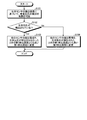
- FIG. 3 is a flowchart illustrating an example of a processing procedure of sensor control by the portable device.
- FIG. 4 is a flowchart illustrating another example of the sensor control processing procedure performed by the portable device.
- portable devices A plurality of embodiments for carrying out a portable electronic device, a control method, and a control program according to the present application will be described in detail with reference to the drawings.
- a portable device will be described as an example of the portable electronic device.
- portable devices include, but are not limited to, wearable devices, smartphones, feature phones, other cellular phones, handsets, and the like.
- FIG. 1 is a diagram illustrating an example of mounting the mobile device 1.
- the portable device 1 is worn on the user's body.
- the mobile device 1 is attached to the user's wrist. Wearing on the user's body includes, for example, mounting the mobile device 1 on the wrist, arm, etc. of the user, housing the mobile device 1 in the user's pocket, and the like.
- the mobile device 1 has a main body 20 and a mounting part 30.
- the main body portion 20 is fixed to the mounting portion 30.
- the mounting unit 30 is a wristband for mounting the main body unit 20 on the user's body.
- the portable device 1 includes a state in which the portable device 1 is worn on the user's body and a state in which the portable device 1 is not worn on the user's body.
- the portable device 1 collects information about the user by being worn on the user's body.
- Information about the user includes, for example, information about the user's living body, information about the user's movement state, information about the user's surrounding environment, and the like.
- the portable device 1 has a touch screen display 2 provided on the main surface (front surface) of the main body 20.
- the touch screen display 2 has a circular shape along the periphery of the main surface.
- the touch screen display 2 has a function of displaying a screen including various types of information such as characters, graphics, and images. Further, the touch screen display 2 has a function of detecting contact of various objects such as a finger, a stylus, and a pen.
- the mobile device 1 can determine a user operation regarding the screen displayed on the touch screen display 2 based on the contact detected by the touch screen display 2.
- the portable device 1 has a plurality of sensors.
- the portable device 1 can control driving of a plurality of sensors and detect various information by the plurality of sensors.
- the portable device 1 can perform processing based on detection results detected by a plurality of sensors.
- the portable device 1 can collect and store the detected detection results.
- FIG. 2 is a block diagram illustrating a functional configuration of the mobile device 1.
- the mobile device 1 includes a touch screen display 2, a communication unit 4, a camera 5, a microphone 6, a speaker 7, a storage unit 9, a control unit 10, an illuminance sensor 11, It includes a proximity sensor 12, an acceleration sensor 13, an orientation sensor 14, a gyro sensor 15, and a biological sensor 16.
- the touch screen display 2 has a display 2a and a touch screen 2b superimposed on the display 2a.
- the display 2a includes a display device such as a liquid crystal display (Liquid Crystal Display), an organic EL display (Organic Electro-Luminescence Display), or an inorganic EL display (Inorganic Electro-Luminescence Display).
- the display 2a can display characters, figures, images, and the like.
- the touch screen 2b can detect contact of a finger, a pen, a stylus pen, or the like with the touch screen 2b.
- the touch screen 2b can detect a position where a plurality of fingers, a pen, a stylus pen, or the like contacts the touch screen 2b.
- the detection method of the touch screen 2b may be any method such as a capacitance method, a resistive film method, a surface acoustic wave method (or an ultrasonic method), an infrared method, an electromagnetic induction method, and a load detection method.
- a capacitance method a resistive film method
- a surface acoustic wave method or an ultrasonic method
- an infrared method an electromagnetic induction method
- an electromagnetic induction method an electromagnetic induction method
- the portable device 1 is based on at least one of the contact detected by the touch screen 2b, the position at which the contact is detected, the change in the position at which the contact is detected, the interval at which the contact is detected, and the number of times the contact is detected. To determine the type of gesture.
- the gesture includes an operation performed on the touch screen 2b.
- the gestures discriminated by the portable device 1 include, but are not limited to, touch, long touch, release, swipe, tap, double tap, long tap, drag, flick, pinch in, and pinch out, for example.
- the portable device 1 can operate according to these gestures determined via the touch screen 2b.
- the mobile device 1 realizes operability that is intuitive and easy to use for the user.
- the operation performed by the mobile device 1 in accordance with the determined gesture includes different operations depending on the screen displayed on the display 2a.
- the touch screen 2b detects contact
- the mobile device 1 determines that the gesture type is X based on the detected contact
- the controller detects X”.
- the communication unit 4 communicates wirelessly.
- the communication method supported by the communication unit 4 is a wireless communication standard.
- wireless communication standards include cellular phone communication standards such as 2G, 3G, and 4G.
- As communication standards of cellular phones for example, LTE (Long Term Evolution), W-CDMA (Wideband Code Multiple Access), CDMA2000, PDC (Personal Digital Cellular), GSM (Regular Trademark) (GloSbMoS) (Personal Handy-phone System).
- wireless communication standards for example, WiMAX (Worldwide Interoperability for Microwave Access), IEEE802.11, Bluetooth (registered trademark), IrDA (Infrared Data Association), NFC (NearCoal, etc.) are included.
- the communication unit 4 may support one or more of the communication standards described above.
- the camera 5 can convert the captured image into an electrical signal and output it to the control unit 10.
- the microphone 6 can convert a user's voice or the like into a sound signal and output the sound signal to the control unit 10.
- the speaker 7 can output the sound signal transmitted from the control unit 10 as sound.
- the storage unit 9 can store programs and data.
- the storage unit 9 is also used as a work area for temporarily storing the processing result of the control unit 10.
- the storage unit 9 may include any non-transitory storage medium such as a semiconductor storage medium and a magnetic storage medium.
- the storage unit 9 may include a plurality of types of storage media.
- the storage unit 9 may include a combination of a portable storage medium such as a memory card, an optical disk, or a magneto-optical disk and a storage medium reader.
- the storage unit 9 may include a storage device used as a temporary storage area such as a RAM (Random Access Memory).
- the program stored in the storage unit 9 includes an application executed in the foreground or the background and a control program for realizing the basic functions of the mobile device 1.
- the application can display a screen on the display 2a, and can cause the control unit 10 to execute a process corresponding to a gesture detected via the touch screen 2b.
- the control program includes an OS, for example.
- the application and the control program may be installed in the storage unit 9 via communication by the communication unit 4 or a non-transitory storage medium.
- the storage unit 9 can store, for example, a control program 9a, setting data 9b, and detection data 9c.
- the control program 9 a can provide functions related to various controls for operating the mobile device 1.
- the control program 9a can realize a call by controlling the communication unit 4, the microphone 6, the speaker 7, and the like, for example.
- the function provided by the control program 9a includes a function of controlling the operation of the portable device 1 in accordance with a gesture on the touch screen 2b.
- the setting data 9b can hold various setting values related to the operation of the mobile device 1.
- the setting data 9b includes, for example, a determination condition for determining that the mobile device 1 is worn on the user's body.
- the determination conditions include conditions such as a determination threshold value and a determination time for determining that the user is wearing the body based on the detection result of the biometric sensor 16.
- the detection data 9c can hold information about users detected by a plurality of sensors.
- the plurality of sensors include, but are not limited to, an illuminance sensor 11, a proximity sensor 12, an acceleration sensor 13, an orientation sensor 14, a gyro sensor 15, and a biological sensor 16.
- the plurality of sensors may include, for example, a temperature sensor, an ultraviolet sensor, a GPS (Global Positioning System) receiver, and the like.
- detection information indicating detection results by a plurality of sensors is stored for each of the plurality of sensors.
- the detection information includes items such as a time detected by the sensor and a value detected by the sensor.
- the control unit 10 has an arithmetic processing unit.
- the arithmetic processing unit includes, for example, a CPU (Central Processing Unit), an SoC (System-on-a-chip), an MCU (Micro Control Unit), an FPGA (Field-Programmable Gate Array), and a coprocessor. It is not limited.
- the control unit 10 may include a plurality of arithmetic devices.
- the control unit 10 can comprehensively control the operation of the mobile device 1. Various functions of the control unit 10 are realized based on the control of the control unit 10. Specifically, the control unit 10 can refer to the data stored in the storage unit 9 as necessary. The control unit 10 controls various devices according to data and instructions. The control unit 10 realizes various functions by controlling the device.
- the control unit 10 can control driving of a plurality of sensors by executing the control program 9a.
- the control unit 10 can collect and store the detection results of the plurality of sensors in the detection data 9c.
- the control unit 10 can perform processing according to the detection results of the plurality of sensors.
- the plurality of sensors can detect the detection target according to the detection cycle and output the detection result to the control unit 10.
- the start and stop of operations of the plurality of sensors are controlled by the control unit 10.
- the plurality of sensors have a function of changing the detection cycle based on a change request from the control unit 10. If a some sensor changes a detection period according to the change request from the control part 10, it can detect a detection target based on the changed detection period.
- the detection cycle of each sensor is set in the setting data 9b.
- the setting data 9b includes cycle information.
- the period information includes items such as a first detection period and a second detection period.
- the first detection cycle includes a cycle corresponding to a case where the first detection cycle is worn on the user's body.
- the first detection period may be different for all or some of the sensors.
- the first detection period may be common to all or some of the sensors.
- the second detection cycle includes a cycle corresponding to a case where the second detection cycle is not worn on the user's body.
- the second detection period may be different for all or some of the sensors.
- the second detection period may be common to all or some of the sensors.
- the first detection cycle of one sensor is set to a cycle shorter than the second detection cycle.
- Some sensors may be set to the same cycle when worn on the user's body and when not worn on the user's body. For example, a period for reducing the power consumption of the mobile device 1 is set as the second detection period. Note that the first detection period is set to a period shorter than the second detection period, thereby increasing the sampling rate of the sensor when worn on the user's body than when not wearing the user's body. be able to.
- the control unit 10 can realize a process of changing the detection cycle by another sensor different from the biological sensor 16 by executing the control program 9 a.
- the other sensors include all or some of a plurality of sensors different from the biosensor 16.
- the illuminance sensor 11 can detect the illuminance of the ambient light of the portable device 1 for each detection cycle.
- the illuminance includes the value of the light beam incident on the unit area of the measurement surface of the illuminance sensor 11.
- the illuminance sensor 11 is used for adjusting the luminance of the display 2a, for example.
- the proximity sensor 12 can detect the presence of a nearby object in a non-contact manner for each detection cycle.
- the proximity sensor 12 can detect the presence of an object based on a change in a magnetic field or a change in the return time of an ultrasonic reflected wave.
- the proximity sensor 12 can detect, for example, that the touch screen display 2 is close to the face.
- the illuminance sensor 11 and the proximity sensor 12 may be configured as one sensor.
- the illuminance sensor 11 may be used as a proximity sensor.
- the acceleration sensor 13 can detect the direction and magnitude of acceleration acting on the mobile device 1, the tilt angle of the mobile device 1, and the magnitude and direction of gravity acceleration for each detection cycle.
- the direction sensor 14 can detect the direction of geomagnetism for each detection period.
- the gyro sensor 15 can detect the angle and angular velocity of the portable device 1 for each detection cycle. The detection results of the acceleration sensor 13, the azimuth sensor 14, and the gyro sensor 15 are used in combination to detect changes in the position, posture, and state of the mobile device 1.
- the biological sensor 16 can detect a biological reaction for each detection cycle.
- the biological sensor 16 may detect a heartbeat as a biological reaction.
- the biological sensor 16 may detect the heartbeat as a biological reaction.
- the biological sensor 16 may detect an electrical signal emitted from the heart as a biological reaction.
- the biosensor 16 may be configured using an infrared sensor or the like when detecting a heartbeat as a biological reaction.
- the living body sensor 16 may be configured using an acceleration sensor or the like when detecting heartbeat as a living body reaction.
- the biosensor 16 may be configured using a potential sensor or the like when detecting an electrical signal generated by the heart as a biological reaction.
- the portable device 1 will be described with respect to a case where the biological sensor 16 detects a heartbeat as a biological reaction, but is not limited thereto.
- the mobile device 1 may be configured to detect that an object is nearby as a biological reaction.
- an acceleration pattern corresponding to the user's action acts on the mobile device 1.
- the mobile device 1 may be configured to detect an acceleration pattern corresponding to the user's action as a biological reaction.
- the portable device 1 When the user does not wear the portable device 1 on the body, the portable device 1 causes the biosensor 16 to be detected in the first detection cycle among the plurality of sensors, and other sensors different from the biosensor 16 are detected in the first detection cycle. It is made to detect with the 2nd detection cycle longer than.
- the other sensors When the portable device 1 is not worn on the body, the other sensors perform detection at a lower sampling rate than when the portable device 1 is worn on the body.
- the biological sensor 16 cannot detect a user's biological reaction.
- the portable device 1 collects detection results detected by other sensors in the second detection cycle and stores them in the detection data 9c.
- the biosensor 16 detects the bioreaction of the user.
- the portable device 1 changes the detection cycle of the other sensor to the first detection cycle shorter than the second detection cycle.
- the other sensors perform detection at a higher sampling rate than when the portable device 1 is not worn on the body.
- the portable device 1 collects detection results detected by other sensors in the first detection cycle and stores them in the detection data 9c.
- the portable device 1 changes the detection cycle by other sensors depending on whether or not a biological reaction is detected.
- the portable apparatus 1 can perform autonomous control according to a user's wearing state.
- the mobile device 1 is not worn on the user's body by changing the detection cycle of the other sensor to a detection cycle longer than when the biological reaction is detected. Power consumption can be reduced.
- the portable device 1 can reduce the device size by reducing the power consumption and the battery size.
- the portable device 1 can eliminate the user's operation by automatically changing the detection period of the other sensor according to the user's wearing on the body.
- the portable device 1 can achieve power saving without reducing convenience.
- the biological sensor 16 cannot detect the biological reaction of the user. If it determines with the portable apparatus 1 not having detected the biological reaction based on the detection result of the biosensor 16, it will change the detection period of another sensor into the 2nd detection period longer than a 1st detection period. Thereby, the other sensors can perform detection at a lower sampling rate than when the portable device 1 is attached to the body by being removed from the body. When the user does not wear the portable device 1, the portable device 1 can collect the detection results detected by other sensors in the second detection cycle and store them in the detection data 9c.
- FIG. 3 is a flowchart illustrating an example of a processing procedure of sensor control by the mobile device 1.
- the processing procedure shown in FIG. 3 is realized by the control unit 10 executing the control program 9a.
- the processing procedure shown in FIG. 3 is repeatedly executed.
- the control unit 10 of the mobile device 1 determines whether or not a biological reaction is detected based on the detection result of the biological sensor 16 in step S101. For example, when a biological reaction is detected by the biological sensor 16, the user is likely to wear the portable device 1 on the body. For this reason, the control part 10 discriminate
- step S102 When the biological reaction is detected (step S102, Yes), the control unit 10 proceeds to step S103.
- step S103 the control unit 10 changes the detection cycle of the other sensor to a first detection cycle that is shorter than the second detection cycle when no biological reaction is detected. Specifically, the control unit 10 outputs a change request to the first detection cycle to each of other sensors different from the biological sensor 16. Thereafter, the control unit 10 ends the processing procedure shown in FIG.
- step S104 the control unit 10 changes the detection cycle of the other sensor to a second detection cycle that is longer than the first detection cycle when the biological reaction is detected. Specifically, the control unit 10 outputs a change request to the second detection cycle to each of other sensors different from the biological sensor 16. Thereafter, the control unit 10 ends the processing procedure shown in FIG.
- the portable device 1 has the same configuration as the portable device 1 shown in FIG. 2 except that the function of the control program 9a is different.
- the portable device 1 detects another sensor different from the biological sensor 16 in the first detection cycle, and detects the biological sensor 16 with a predetermined detection. It is detected by the period. For this reason, another sensor detects a detection target when the portable device 1 is worn on the body. And when the portable apparatus 1 is mounted
- the biological sensor 16 cannot detect the biological reaction of the user.
- the portable device 1 stops the detection by the other sensor.
- the portable device 1 stops the detection by the other sensor by changing the detection cycle of the other sensor to a value meaning the operation stop.
- the portable device 1 stops detection by other sensors by outputting a stop request to a plurality of sensors. Accordingly, the other sensors automatically stop the detection operation when the portable device 1 is removed from the body.
- the biological sensor 16 cannot detect a user's biological reaction.
- the detection results of the other sensors are not collected.
- the portable device 1 stops the detection by the other sensors when the biological sensor 16 does not detect the biological reaction. Thereby, the portable apparatus 1 can reduce the power consumption when not wearing with respect to a user's body according to a user's wearing state.
- the portable device 1 can control the start and stop of other sensors according to the user's body attachment, thereby eliminating the need for the user's operation, thus reducing power consumption without reducing convenience. Can be planned.
- the biosensor 16 can detect the biological reaction of the user.
- the portable device 1 changes the detection cycle by the other sensors from the stopped state to the first detection cycle.
- the portable device 1 causes another sensor to start detection based on the first detection cycle. Accordingly, the other sensors detect the detection target when the portable device 1 is worn on the body, and do not perform the detection operation when the portable device 1 is not worn on the body.
- the mobile device 1 collects and stores the detection results detected by the other sensors in the first detection cycle in the detection data 9c.
- FIG. 4 is a flowchart illustrating another example of the sensor control processing procedure performed by the mobile device 1.
- the processing procedure shown in FIG. 4 is realized by the control unit 10 executing the control program 9a.
- the processing procedure shown in FIG. 4 is repeatedly executed.
- the control unit 10 of the portable device 1 determines whether or not a biological reaction is detected based on the detection result of the biological sensor 16 in step S201. For example, when a biological reaction is detected by the biological sensor 16, the user is likely to wear the portable device 1 on the body. For this reason, the control part 10 discriminate
- step S202 If the biological reaction is detected (step S202, Yes), the control unit 10 proceeds to step S203.
- step S203 If the detection by another sensor is stopped (step S203, Yes), the control unit 10 proceeds to step S204.
- the control part 10 starts the detection by another sensor as step S204. For example, the control unit 10 detects a plurality of sensors in the first detection cycle. Thereafter, the control unit 10 ends the processing procedure shown in FIG.
- step S202 the control unit 10 proceeds to step S205.
- step S205 the control unit 10 determines whether detection by other sensors is stopped. When detection by another sensor is being stopped (step S205, Yes), the control unit 10 ends the processing procedure illustrated in FIG.
- step S205 If the detection by another sensor is not stopped (step S205, No), the control unit 10 proceeds to step S206. Control part 10 stops detection by other sensors as Step S206. Thereafter, the control unit 10 ends the processing procedure shown in FIG.
- each program shown in FIG. 2 may be divided into a plurality of modules, or may be combined with other programs.
- the mobile device 1 makes the detection cycle of another sensor different from the biological sensor 16 longer, shorter, or stopped according to the wearing state of the user. It is not limited to.
- the mobile device 1 may be configured to change the detection cycle by the biosensor 16 while changing the detection cycle by another sensor.
- the case where the portable device 1 detects a biological reaction in accordance with the presence or absence of detection by the biological sensor 16 is not limited to this.
- the mobile device 1 may determine whether or not a biological reaction is detected using a sensor different from the biological sensor 16, and may change the detection cycle of other sensors including the biological sensor 16.
- the mobile device 1 may change the detection cycle of other sensors (including the biological sensor 16) different from the proximity sensor 12 according to the detection result of the object by the proximity sensor 12.
- the portable apparatus 1 can collect the detection results related to the user's living body by the living body sensor 16 according to the wearing by the user.
- the portable device 1 has been described as an example of the portable electronic device, but the portable electronic device according to the appended claims is not limited to the portable device 1.
- the portable electronic device according to the appended claims may be a portable electronic device other than the portable device 1. Examples of the portable electronic device include, but are not limited to, a pedometer, a sleep meter, a tablet, a portable personal computer, a digital camera, a media player, an electronic book reader, a navigator, and a game machine.
- the description “detect” can be understood in the meanings of measure, scale, and sense depending on the situation.
- the description of “state” can be understood as “situation” depending on the situation.
- the movement state can be understood as a movement state.
- the state of the portable electronic device can be understood as the state of the portable electronic device.
Landscapes
- Health & Medical Sciences (AREA)
- Life Sciences & Earth Sciences (AREA)
- Engineering & Computer Science (AREA)
- Biomedical Technology (AREA)
- General Health & Medical Sciences (AREA)
- Medical Informatics (AREA)
- Public Health (AREA)
- Physics & Mathematics (AREA)
- Pathology (AREA)
- Biophysics (AREA)
- Heart & Thoracic Surgery (AREA)
- Molecular Biology (AREA)
- Surgery (AREA)
- Animal Behavior & Ethology (AREA)
- Veterinary Medicine (AREA)
- Physiology (AREA)
- Signal Processing (AREA)
- Cardiology (AREA)
- Computer Networks & Wireless Communication (AREA)
- Business, Economics & Management (AREA)
- General Business, Economics & Management (AREA)
- Epidemiology (AREA)
- Primary Health Care (AREA)
- General Physics & Mathematics (AREA)
- Spectroscopy & Molecular Physics (AREA)
- Artificial Intelligence (AREA)
- Computer Vision & Pattern Recognition (AREA)
- Psychiatry (AREA)
- Radar, Positioning & Navigation (AREA)
- Dentistry (AREA)
- Oral & Maxillofacial Surgery (AREA)
- Telephone Function (AREA)
- User Interface Of Digital Computer (AREA)
- Measuring Pulse, Heart Rate, Blood Pressure Or Blood Flow (AREA)
- Measuring And Recording Apparatus For Diagnosis (AREA)
Abstract
Il y est portée pour l'amélioration dans des instruments électronique portable, par exemple par rapport à commande par laquelle une pluralité de capteurs détecter des informations. Par exemple, ce dispositif électronique portable 1 est pourvu : d'une pluralité de capteurs; une unité de détection qui détecte une réaction biologique à l'aide de l'un des capteurs; et une unité de commande 10 qui commande des changements dans le cycle de détection d'autres capteurs en fonction de si oui ou non la réaction biologique a été détecté. Par exemple, l'unité de commande 10 change le cycle de détection à être plus courte lorsque la réaction biologique a été détecté que le cycle de détection lorsque la réaction biologique n'a pas été détectée.
Priority Applications (2)
| Application Number | Priority Date | Filing Date | Title |
|---|---|---|---|
| US15/538,195 US20170354371A1 (en) | 2014-12-24 | 2015-12-21 | Mobile electronic device, control method and non-transitory storage medium |
| EP15872999.6A EP3240262A4 (fr) | 2014-12-24 | 2015-12-21 | Instrument électronique portable, procédé de commande, et programme de commande |
Applications Claiming Priority (2)
| Application Number | Priority Date | Filing Date | Title |
|---|---|---|---|
| JP2014261289A JP2016122927A (ja) | 2014-12-24 | 2014-12-24 | 携帯電子機器、制御方法、及び制御プログラム |
| JP2014-261289 | 2014-12-24 |
Publications (1)
| Publication Number | Publication Date |
|---|---|
| WO2016104431A1 true WO2016104431A1 (fr) | 2016-06-30 |
Family
ID=56150450
Family Applications (1)
| Application Number | Title | Priority Date | Filing Date |
|---|---|---|---|
| PCT/JP2015/085682 Ceased WO2016104431A1 (fr) | 2014-12-24 | 2015-12-21 | Instrument électronique portable, procédé de commande, et programme de commande |
Country Status (4)
| Country | Link |
|---|---|
| US (1) | US20170354371A1 (fr) |
| EP (1) | EP3240262A4 (fr) |
| JP (1) | JP2016122927A (fr) |
| WO (1) | WO2016104431A1 (fr) |
Families Citing this family (2)
| Publication number | Priority date | Publication date | Assignee | Title |
|---|---|---|---|---|
| JP2021097924A (ja) * | 2019-12-23 | 2021-07-01 | 日本電産モビリティ株式会社 | 生体情報検出装置、生体情報検出方法、および生体情報検出プログラム |
| JP7711520B2 (ja) * | 2021-09-21 | 2025-07-23 | カシオ計算機株式会社 | 電子機器、装着判定方法及びプログラム |
Citations (3)
| Publication number | Priority date | Publication date | Assignee | Title |
|---|---|---|---|---|
| JP2003070757A (ja) * | 2001-09-06 | 2003-03-11 | Seiko Instruments Inc | 脈拍計 |
| JP2008246176A (ja) * | 2007-03-30 | 2008-10-16 | Matsushita Electric Works Ltd | 体動計測機器 |
| JP2014238695A (ja) * | 2013-06-07 | 2014-12-18 | セイコーエプソン株式会社 | 電子機器及びタップ操作検出方法 |
Family Cites Families (6)
| Publication number | Priority date | Publication date | Assignee | Title |
|---|---|---|---|---|
| JP4666319B2 (ja) * | 2008-03-31 | 2011-04-06 | Necシステムテクノロジー株式会社 | 生体装着型データ通信装置 |
| WO2011076884A2 (fr) * | 2009-12-23 | 2011-06-30 | Delta, Dansk Elektronik, Lys Og Akustik | Système de surveillance |
| US20110213217A1 (en) * | 2010-02-28 | 2011-09-01 | Nellcor Puritan Bennett Llc | Energy optimized sensing techniques |
| US9005129B2 (en) * | 2012-06-22 | 2015-04-14 | Fitbit, Inc. | Wearable heart rate monitor |
| US9044171B2 (en) * | 2012-06-22 | 2015-06-02 | Fitbit, Inc. | GPS power conservation using environmental data |
| US20150173666A1 (en) * | 2013-12-20 | 2015-06-25 | Integrated Bionics, LLC | In-Situ Concussion Monitor |
-
2014
- 2014-12-24 JP JP2014261289A patent/JP2016122927A/ja active Pending
-
2015
- 2015-12-21 WO PCT/JP2015/085682 patent/WO2016104431A1/fr not_active Ceased
- 2015-12-21 US US15/538,195 patent/US20170354371A1/en not_active Abandoned
- 2015-12-21 EP EP15872999.6A patent/EP3240262A4/fr not_active Withdrawn
Patent Citations (3)
| Publication number | Priority date | Publication date | Assignee | Title |
|---|---|---|---|---|
| JP2003070757A (ja) * | 2001-09-06 | 2003-03-11 | Seiko Instruments Inc | 脈拍計 |
| JP2008246176A (ja) * | 2007-03-30 | 2008-10-16 | Matsushita Electric Works Ltd | 体動計測機器 |
| JP2014238695A (ja) * | 2013-06-07 | 2014-12-18 | セイコーエプソン株式会社 | 電子機器及びタップ操作検出方法 |
Non-Patent Citations (1)
| Title |
|---|
| See also references of EP3240262A4 * |
Also Published As
| Publication number | Publication date |
|---|---|
| US20170354371A1 (en) | 2017-12-14 |
| EP3240262A1 (fr) | 2017-11-01 |
| EP3240262A4 (fr) | 2018-05-30 |
| JP2016122927A (ja) | 2016-07-07 |
Similar Documents
| Publication | Publication Date | Title |
|---|---|---|
| US8665238B1 (en) | Determining a dominant hand of a user of a computing device | |
| US9965033B2 (en) | User input method and portable device | |
| US10198118B2 (en) | Operating method and electronic device for processing method thereof | |
| US9237601B2 (en) | Mobile device function selection using position in relation to a user | |
| US10268364B2 (en) | Electronic device and method for inputting adaptive touch using display of electronic device | |
| US9836275B2 (en) | User device having a voice recognition function and an operation method thereof | |
| US10559273B2 (en) | Display screen control method and apparatus and terminal | |
| US9600177B2 (en) | Electronic device with gesture display control and corresponding methods | |
| CN109314727B (zh) | 一种控制移动终端屏幕的方法及装置 | |
| US20180007192A1 (en) | Electronic device, control method, and non-transitory storage medium | |
| WO2015098706A1 (fr) | Dispositif électronique mobile, procédé de commande et programme de commande | |
| US20180081536A1 (en) | Electronic device | |
| KR20180067139A (ko) | 위치 데이터를 제공하는 전자 장치 및 그 방법 | |
| KR102555229B1 (ko) | 전자 장치 및 전자 장치의 제어 방법 | |
| JP6185031B2 (ja) | 携帯機器、制御方法及び制御プログラム | |
| EP2703978B1 (fr) | Appareil de mesure de coordonnées et procédé de commande de celui-ci | |
| JP6543173B2 (ja) | 携帯電子機器、制御方法および制御プログラム | |
| JP2016122927A (ja) | 携帯電子機器、制御方法、及び制御プログラム | |
| KR20180026924A (ko) | 동작을 제어하는 전자 장치 및 방법 | |
| JP2018037819A (ja) | 電子機器、制御方法及びプログラム | |
| JP6391768B2 (ja) | 携帯機器、制御方法及び制御プログラム | |
| JP6223383B2 (ja) | 携帯装置、制御方法、及び制御プログラム | |
| US20170337833A1 (en) | Education support system | |
| CN103999472A (zh) | 用于在电子设备处利用流内容的方法和装置 | |
| US20170094615A1 (en) | Electronic device, control method, and non-transitory storage medium thereof |
Legal Events
| Date | Code | Title | Description |
|---|---|---|---|
| 121 | Ep: the epo has been informed by wipo that ep was designated in this application |
Ref document number: 15872999 Country of ref document: EP Kind code of ref document: A1 |
|
| REEP | Request for entry into the european phase |
Ref document number: 2015872999 Country of ref document: EP |
|
| WWE | Wipo information: entry into national phase |
Ref document number: 15538195 Country of ref document: US |
|
| NENP | Non-entry into the national phase |
Ref country code: DE |