WO2016104501A1 - Système de gestion d'énergie électrique, dispositif de relais et procédé de gestion d'énergie électrique - Google Patents
Système de gestion d'énergie électrique, dispositif de relais et procédé de gestion d'énergie électrique Download PDFInfo
- Publication number
- WO2016104501A1 WO2016104501A1 PCT/JP2015/085828 JP2015085828W WO2016104501A1 WO 2016104501 A1 WO2016104501 A1 WO 2016104501A1 JP 2015085828 W JP2015085828 W JP 2015085828W WO 2016104501 A1 WO2016104501 A1 WO 2016104501A1
- Authority
- WO
- WIPO (PCT)
- Prior art keywords
- power management
- smart meter
- wireless connection
- relay device
- relay
- Prior art date
- Legal status (The legal status is an assumption and is not a legal conclusion. Google has not performed a legal analysis and makes no representation as to the accuracy of the status listed.)
- Ceased
Links
Images



Classifications
-
- H—ELECTRICITY
- H04—ELECTRIC COMMUNICATION TECHNIQUE
- H04B—TRANSMISSION
- H04B17/00—Monitoring; Testing
- H04B17/40—Monitoring; Testing of relay systems
-
- H—ELECTRICITY
- H04—ELECTRIC COMMUNICATION TECHNIQUE
- H04B—TRANSMISSION
- H04B7/00—Radio transmission systems, i.e. using radiation field
- H04B7/14—Relay systems
- H04B7/15—Active relay systems
-
- H—ELECTRICITY
- H04—ELECTRIC COMMUNICATION TECHNIQUE
- H04Q—SELECTING
- H04Q9/00—Arrangements in telecontrol or telemetry systems for selectively calling a substation from a main station, in which substation desired apparatus is selected for applying a control signal thereto or for obtaining measured values therefrom
-
- H—ELECTRICITY
- H04—ELECTRIC COMMUNICATION TECHNIQUE
- H04W—WIRELESS COMMUNICATION NETWORKS
- H04W4/00—Services specially adapted for wireless communication networks; Facilities therefor
- H04W4/24—Accounting or billing
-
- H—ELECTRICITY
- H04—ELECTRIC COMMUNICATION TECHNIQUE
- H04Q—SELECTING
- H04Q2209/00—Arrangements in telecontrol or telemetry systems
- H04Q2209/40—Arrangements in telecontrol or telemetry systems using a wireless architecture
-
- H—ELECTRICITY
- H04—ELECTRIC COMMUNICATION TECHNIQUE
- H04Q—SELECTING
- H04Q2209/00—Arrangements in telecontrol or telemetry systems
- H04Q2209/60—Arrangements in telecontrol or telemetry systems for transmitting utility meters data, i.e. transmission of data from the reader of the utility meter
-
- H—ELECTRICITY
- H04—ELECTRIC COMMUNICATION TECHNIQUE
- H04Q—SELECTING
- H04Q2213/00—Indexing scheme relating to selecting arrangements in general and for multiplex systems
- H04Q2213/13107—Control equipment for a part of the connection, distributed control, co-processing
-
- Y—GENERAL TAGGING OF NEW TECHNOLOGICAL DEVELOPMENTS; GENERAL TAGGING OF CROSS-SECTIONAL TECHNOLOGIES SPANNING OVER SEVERAL SECTIONS OF THE IPC; TECHNICAL SUBJECTS COVERED BY FORMER USPC CROSS-REFERENCE ART COLLECTIONS [XRACs] AND DIGESTS
- Y02—TECHNOLOGIES OR APPLICATIONS FOR MITIGATION OR ADAPTATION AGAINST CLIMATE CHANGE
- Y02D—CLIMATE CHANGE MITIGATION TECHNOLOGIES IN INFORMATION AND COMMUNICATION TECHNOLOGIES [ICT], I.E. INFORMATION AND COMMUNICATION TECHNOLOGIES AIMING AT THE REDUCTION OF THEIR OWN ENERGY USE
- Y02D30/00—Reducing energy consumption in communication networks
- Y02D30/70—Reducing energy consumption in communication networks in wireless communication networks
Definitions
- the present invention relates to a power management system, a relay device, and a power management method used in a customer facility provided with a smart meter.
- EMS Energy Management System
- a power management apparatus that manages power is provided.
- a smart meter having a communication function is known as a meter for measuring power supplied from a power system to a customer facility.
- a smart meter is a device provided by an electric power company or the like, and power information obtained by the smart meter is used for charging a user.
- the transmission power of the wireless signal from the smart meter may be set low in order to reduce interference between the smart meters.
- the power management device can be installed at a limited position, the power management device cannot always be installed around the smart meter.
- a relay device measures a first wireless communication unit that establishes a wireless connection with a smart meter having a wireless communication function, measures a first signal quality of a wireless signal from the smart meter, and And a control unit that performs control for presenting the signal quality of 1 to the user.
- the relay device relays communication between the smart meter and a power management device that manages power information obtained by the smart meter.
- the relay device measures the first signal quality of a wireless signal from a smart meter having a wireless communication function, and the relay device measures the first signal quality.
- the relay device Presenting to a user; the relay device establishing a wireless connection with the smart meter; and the relay device managing power information obtained by the smart meter and the smart meter; Relaying communications between the two.
- a power management system establishes a wireless connection between a power management device that manages power information and a smart meter having a wireless communication function, and performs communication between the smart meter and the power management device.
- a relay device for relaying The relay device performs an authentication process with the smart meter, and establishes a wireless connection with the smart meter when the authentication process is successful.
- the relay device includes a control unit that performs authentication processing with a smart meter having a wireless communication function and establishes wireless connection with the smart meter when the authentication processing is successful.
- the relay device relays communication between the smart meter and the power management device.
- a power management method includes a step in which the relay device performs authentication processing with a smart meter having a wireless communication function, and the relay device wirelessly communicates with the smart meter when the authentication processing is successful. Establishing a connection, and the relay device relaying communication between the smart meter and a power management device.
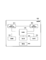
- FIG. 1 is a block diagram of a power management system according to the first to third embodiments.
- FIG. 2 is a diagram illustrating a configuration of a customer facility according to the first embodiment and the second embodiment.
- FIG. 3 is a block diagram of the relay device according to the first embodiment and the second embodiment.
- FIG. 4 is a diagram illustrating an implementation example of the relay device according to the first embodiment.
- FIG. 5 is a block diagram of the power management apparatus according to the first to third embodiments.
- FIG. 6 is a sequence diagram illustrating an example of an operation sequence of the power management system according to the first embodiment.
- FIG. 7 is a diagram illustrating an implementation example of the relay device according to the second embodiment.
- FIG. 8 is a block diagram of a relay device according to the third embodiment.
- FIG. 1 is a block diagram of the power management system 10.
- a solid line between blocks indicates a power line
- a broken line between blocks indicates a signal line.
- the power management system 10 includes a load 100, a distribution board 110, a PV (Photovoltaic) device 130, a storage battery device 140, a power management device 200, a display device 290, a smart meter 300, and a relay device 400.
- a load 100 a distribution board 110
- a PV (Photovoltaic) device 130 a storage battery device 140
- a power management device 200 a display device 290, a smart meter 300, and a relay device 400.
- the load 100 is a device that consumes electric power supplied via a power line.
- the load 100 may be a single device or may include a plurality of devices.
- the load 100 includes a refrigerator, lighting, an air conditioner, a television, or the like.
- Distribution board 110 is a device that distributes power and the like.
- the distribution board 110 is connected to a power system 11 provided by an electric power company or the like.
- the distribution board 110 is connected to the load 100, the PV device 130, and the storage battery device 140 through a power line.
- the distribution board 110 may be connected to the power management apparatus 200 and the relay apparatus 400 via a power line.
- the PV device 130 is a device that generates power, and includes a PV 131 and a PCS (Power Conditioning System) 132.
- the PV 131 generates power in response to received sunlight and outputs DC power.
- the PCS 132 converts the DC power output from the PV 131 into AC power, and outputs AC power through the power line.
- the storage battery device 140 is a device that stores electric power, and includes a storage battery 141 and a PCS 142.
- the storage battery 141 stores power (charge) and outputs power (discharge).
- the PCS 142 converts AC power input through the power line into DC power when the storage battery 141 is charged, and outputs the DC power to the storage battery 141.
- the PCS 142 converts the DC power output from the storage battery 141 into AC power when the storage battery 141 is discharged, and outputs the AC power via the power line.
- the power management apparatus 200 is an apparatus that manages power (power information).
- the power management apparatus 200 is connected to the load 100, the PV apparatus 130, the storage battery apparatus 140, the display apparatus 290, and the relay apparatus 400 via signal lines that form a narrow area network (LAN).
- the signal line may be wireless or wired.
- the signal line between the power management apparatus 200 and the relay apparatus 400 is wireless.
- the power management device 200 may control the load 100, the PV device 130, the storage battery device 140, and the display device 290. Details of the power management apparatus 200 will be described later.
- the display device 290 performs various displays under the control of the power management device 200.
- the display device 290 may communicate with the power management device 200 via a wide area network (WAN).
- the display device 290 may be a television, a tablet terminal, a smartphone, or the like.
- the smart meter 300 is a meter device that measures the power supplied from the power system 11.
- the smart meter 300 may measure the power supplied (reverse power flow) from the PV device 130 or the like to the power system 11.
- the reverse power flow refers to, for example, the flow of power flowing from the PV device 130 to the power system 11 side.
- a single smart meter 300 is illustrated in FIG. 1, a plurality of smart meters 300 may be provided.
- Smart meter 300 is a device provided by, for example, an electric power company.
- the power information obtained by the smart meter 300 is used for charging the user.
- the smart meter 300 has a communication function and is connected to the relay device 400 via a signal line.
- the signal line between the smart meter 300 and the relay device 400 is wireless.
- the relay device 400 is a device that relays communication between the power management device 200 and the smart meter 300.
- a communication protocol between the power management apparatus 200 and the smart meter 300 for example, ECHONET Lite (registered trademark, hereinafter the same) is applied.
- a communication protocol is not limited to this, For example, KNX or SEP2.0 can be used. Details of the relay device 400 will be described later.
- FIG. 2 is a diagram illustrating a configuration of the customer facility 20.
- the customer facility 20 is a house.
- the house may be a detached house or a house included in an apartment house (apartment or apartment).
- a power management apparatus 200 and a smart meter 300 are installed in the customer facility 20.
- the power management apparatus 200 installed in a house as the customer facility 20 may be referred to as a HEMS (Home Energy Management System) or a HEMS controller.
- the load 100 and the distribution board 110 shown in FIG. 1 are installed. Furthermore, at least one of the PV device 130 and the storage battery device 140 illustrated in FIG. 1 may be installed in the customer facility 20.
- Such a communication path may be referred to as a “B route”.
- Wi-SUN registered trademark, the same applies hereinafter.
- Wireless communication using a communication standard is applied.
- each of the smart meter 300 and the power management apparatus 200 has a wireless communication function using Wi-SUN. That is, it is possible to establish a wireless connection between the smart meter 300 and the power management apparatus 200 and perform wireless communication between the smart meter 300 and the power management apparatus 200.
- the transmission power of the wireless signal from the smart meter 300 may be set low in order to reduce interference between the smart meters 300. is there.
- B route communication if it is confirmed that even a little wireless signal emitted from the smart meter 300 enters the customer facility 20 when the smart meter 300 is installed, the installation of the smart meter 300 is completed. Because it becomes.
- the position where the power management apparatus 200 can be installed may be limited from the viewpoint of securing a power source or the like.
- the power management apparatus 200 is installed around the distribution board 110 so that it can operate even when the breaker of the distribution board 110 is shut off. Therefore, the power management apparatus 200 cannot always be installed around the smart meter 300.
- the relay device 400 establishes a wireless connection with the smart meter 300 and a wireless connection with the power management device 200, and relays communication between the smart meter 300 and the power management device 200.
- the relay device 400 can establish a good wireless connection with the smart meter 300 and a good wireless connection with the power management device 200. Therefore, the quality of communication between the smart meter 300 and the power management apparatus 200 can be improved.
- the relay device 400 is provided as a set with the power management device 200, for example. That is, the relay device 400 is a device associated with the power management device 200.
- the relay device 400 may be referred to as a “(wireless) adapter”.
- the communication quality can be easily changed by changing the position of the relay apparatus 400 even when the wireless connection status changes due to a change in the surrounding environment. Can be improved.
- the relay device 400 when the relay device 400 is provided as a set with the power management device 200, the power management device 200 may not have a communication function with the smart meter 200.
- the relay device 400 may be provided separately from the power management device 200.
- the relay apparatus 400 is provided separately from the power management apparatus 200, for example, when the power management apparatus 200 is installed, the relay apparatus 400 is unnecessary, but the relay apparatus 400 is necessary afterwards.
- the relay apparatus 400 may be purchased separately. In this case, communication quality can be improved without changing the position of the smart meter 200 or the power management apparatus 200.
- the power information obtained from the smart meter 300 reflects the user's home status in the customer facility 20, it is desired to ensure the security of the power information. That is, it is desirable to prevent a device different from the power management device 200 from communicating with the smart meter 300.
- FIG. 3 is a block diagram of relay device 400.
- the relay device 400 includes a first wireless communication unit 410, a second wireless communication unit 420, a storage unit 430, a display unit 440, an operation unit 450, a power supply unit 460, and a control unit 470. .
- the first wireless communication unit 410 is a block for establishing a wireless connection with the smart meter 300.
- the first wireless communication unit 410 is a Wi-SUN wireless communication unit compliant with the Wi-SUN communication standard.
- the Wi-SUN communication standard uses a radio frequency band less than 1 GHz (for example, a 920 MHz band).
- the second wireless communication unit 420 is a block for establishing a wireless connection with the power management apparatus 200.
- the second wireless communication unit 420 is a WLAN wireless communication unit compliant with a wireless narrow area network (WLAN) communication standard.
- the WLAN communication standard refers to various IEEE 802.11 standards.
- the WLAN communication standard uses a radio frequency band higher than 1 GHz (for example, 2.4 GHz band, 5 GHz band, etc.).
- the communication standard used for the wireless communication (first wireless communication unit 410) between the smart meter 300 and the relay device 400, and between the power management device 200 and the relay device 400.
- the communication standard used for the second wireless communication (second wireless communication unit 420) is different.
- radio waves are transmitted between the first radio communication unit 410 and the second radio communication unit 420. Interference can be made difficult to occur.
- the storage unit 430 is a block that stores information and programs used for control in the relay device 400.
- the storage unit 430 includes a nonvolatile storage medium and a volatile storage medium.
- the storage unit 430 (nonvolatile storage medium) stores first authentication information used for authentication processing with the power management apparatus 200 in advance.
- the first authentication information includes an authentication method and an authentication key.
- the authentication method may be a common key based method or a public key based method.
- the authentication key is, for example, an ID and password used in a common key based method, or a digital certificate used in a public key based method.
- the display unit 440 is a block that performs various displays under the control of the control unit 470.
- the display unit 440 includes at least one liquid crystal display (LCD), at least one light emitting diode (LED), or a combination thereof.
- the display unit 440 includes a plurality of LEDs.
- an audio output unit (speaker, buzzer) that emits sound may be provided.
- a vibration generating unit that generates vibration may be provided.
- the display unit 440, the audio output unit, and the vibration generation unit are used for various presentations to the user.
- the operation unit 450 is a block that receives an operation from the user and transmits the operation content to the control unit 470.
- the operation unit 450 includes at least one button, at least one switch, or a combination thereof.
- the operation unit 450 may be configured integrally with the display unit 440.
- the power supply unit 460 is a block for supplying power to other blocks in the relay device 400.
- the power supply unit 460 is configured by an AC power supply (AC adapter), a battery, or a combination thereof.
- the power supply unit 460 may employ a power supply method using Ethernet (registered trademark, the same applies hereinafter) or wireless power supply.
- the control unit 470 is a block that performs various controls by executing a program stored in the storage unit 430.
- the control unit 470 is configured by at least one processor. In the first embodiment, the control unit 470 controls the first wireless communication unit 410, the second wireless communication unit 420, and the display unit 440.
- the control unit 470 automatically starts searching for a signal emitted from the power management apparatus 200 after power is supplied to the relay apparatus 400.
- the power is supplied to the relay device 400 means that the power switch 450C (see FIG. 4) constituting the operation unit 450 is turned on.
- the relay device 400 does not have the power switch 450C
- the power is supplied to the relay device 400 may be that the power supply unit 460 is connected to an outlet.
- the “signal emitted from the power management apparatus 200” is a WLAN radio signal such as a beacon signal or a probe response signal.
- the control unit 470 When a signal emitted from the power management apparatus 200 is detected by the search, the control unit 470 performs an authentication process with the power management apparatus 200 (hereinafter referred to as “first authentication process”). In the first embodiment, the control unit 470 detects the signal emitted from the power management apparatus 200 by the search, and when the connection button 450B (see FIG. 4) configuring the operation unit 450 is pressed, Perform authentication processing. When relay device 400 does not have connection button 450B, control unit 470 may perform the first authentication process immediately after a signal issued from power management device 200 is detected by the search.
- the control unit 470 performs the first authentication process using the first authentication information stored in the storage unit 430 in advance. When the authentication process with the power management apparatus 200 is successful, the control unit 470 establishes a wireless connection with the power management apparatus 200.
- the first authentication process is a process for confirming the validity of the power management apparatus 200 by acquiring authentication information from the power management apparatus 200 and collating the acquired authentication information with the first authentication information. May be included.
- the first authentication process includes a process of confirming the validity of the relay apparatus 400 by notifying the power management apparatus 200 of the first authentication information and checking the first authentication information in the power management apparatus 200. But you can.
- the relay apparatus 400 (second wireless communication unit 420) is authorized.
- a wireless connection can be established only with the power management apparatus 200. In other words, since the third party device fails in the first authentication process, the wireless connection with the relay device 400 cannot be established.
- the power management apparatus 200 stores second authentication information used for authentication processing with the smart meter 300 in advance. Details of the second authentication information will be described later.
- the control unit 470 acquires the second authentication information from the power management apparatus 200 after establishing a wireless connection with the power management apparatus 200. Further, the control unit 470 automatically starts searching for a signal emitted from the smart meter 300. “Signal emitted from smart meter 300” is a Wi-SUN radio signal. The search for the signal emitted from the smart meter 300 may be started before the second authentication information is acquired from the power management apparatus 200. For example, the control unit 470 may automatically start searching for a signal emitted from the smart meter 300 after power is supplied to the relay device 400.
- the control unit 470 performs authentication processing with the smart meter 300 (hereinafter referred to as “second authentication processing”) using the second authentication information.
- the control unit 470 acquires the second authentication information and performs the second authentication process when the connection button 450A (see FIG. 4) constituting the operation unit 450 is pressed.
- the control unit 470 may perform the second authentication process immediately after acquiring the second authentication information.
- the control unit 470 establishes a wireless connection with the smart meter 300 when the second authentication process is successful.
- the second authentication process may include a process of confirming the validity of the smart meter 300 by acquiring authentication information from the smart meter 300 and checking the acquired authentication information against the second authentication information. Good.
- the second authentication process may include a process of confirming the validity of the relay device 400 by notifying the smart meter 300 of the second authentication information and checking the second authentication information in the smart meter 300. .
- the relay device 400 (the first wireless communication unit 410) is a valid smart meter 300.
- a wireless connection can only be established.
- the control unit 470 performs control for relaying communication between the smart meter 300 and the power management apparatus 200.
- the relay device 400 establishes a wireless connection only with the legitimate power management apparatus 200 and the legitimate smart meter 300, and therefore communication between the power management apparatus 200 and the smart meter 300 is one-to-one communication. Is guaranteed. That is, it is possible to make it difficult for an apparatus different from the power management apparatus 200 to communicate with the smart meter 300 via the relay apparatus 400. Therefore, the security of the power information obtained from the smart meter 300 can be ensured.
- the control unit 470 measures the signal quality of the wireless signal (Wi-SUN wireless signal) from the smart meter 300 (hereinafter referred to as “first signal quality”).
- the signal quality is, for example, a received power level such as RSSI or a received quality level such as SNR.
- the control unit 470 performs control for presenting the first signal quality to the user.
- “present to the user” means display by the display unit 440, audio output by the audio output unit, vibration generation by the vibration generation unit, or a combination thereof.
- “present to the user” means display by the display unit 440, audio output by the audio output unit, vibration generation by the vibration generation unit, or a combination thereof.
- the case where the said presentation is the display by the display part 440 is assumed.
- the user can grasp the first signal quality.
- the control unit 470 performs control to present the first signal quality to the user in a state where the wireless connection with the smart meter 300 is not established. Accordingly, the user can install the relay device 400 at a position where the first signal quality is good, and the relay device 400 can establish a good wireless connection with the smart meter 300.
- the control unit 470 further measures the radio quality (hereinafter referred to as “second signal quality”) of the radio signal (WLAN radio signal) from the power management apparatus 200, and the first signal quality and the second signal are measured. Control the quality to the user.
- second signal quality the radio quality of the radio signal (WLAN radio signal) from the power management apparatus 200
- the user can grasp the second signal quality.
- the control unit 470 performs control to present the second signal quality to the user in a state where the wireless connection with the power management apparatus 200 is not established. Accordingly, the user can install the relay apparatus 400 at a position where the second signal quality is good, and the relay apparatus 400 can establish a good wireless connection with the power management apparatus 200.
- the relay device 400 can establish a good wireless connection with the smart meter 300 and a good wireless connection with the power management device 200. Therefore, the quality of communication between the smart meter 300 and the power management apparatus 200 can be improved.
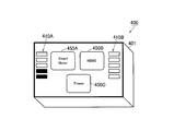
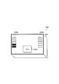
- FIG. 4 is a diagram illustrating an implementation example of the relay device 400 according to the first embodiment.
- the relay device 400 has a rectangular parallelepiped casing 401.
- the housing 401 houses the first wireless communication unit 410, the second wireless communication unit 420, the storage unit 430, the power supply unit 460, and the control unit 470 shown in FIG.
- a display unit 440 and an operation unit 450 are arranged on one surface of the housing 401.
- the display unit 440 and the operation unit 450 are arranged on the same surface of the housing 401.
- the display unit 440 includes a first display unit 410A that displays the first signal quality, and a second display unit 410B that displays the second signal quality.
- each of the first display unit 410A and the second display unit 410B includes a plurality of LEDs.
- Control unit 470 turns on the number of LEDs corresponding to the first signal quality in first display unit 410A.
- the control unit 470 turns on the number of LEDs corresponding to the second signal quality in the second display unit 410B.
- the display mode of the first signal quality on the first display unit 410A is different from the display mode of the second signal quality on the second display unit 410B.
- the display color of the LED in the first display unit 410A is different from the display color of the LED in the second display unit 410B.
- the display shape of the LED in the first display portion 410A is different from the display shape of the LED in the second display portion 410B. Thereby, a user's visibility can be improved.
- the operation unit 450 includes a first operation unit (connection button 450 ⁇ / b> A) that receives a first connection operation that instructs to establish a wireless connection with the smart meter 300 from the user, and the power management apparatus 200. And a second operation unit (connection button 450B) for accepting a second connection operation for instructing establishment of a wireless connection from the user.
- a first operation unit connection button 450 ⁇ / b> A
- connection button 450B for accepting a second connection operation for instructing establishment of a wireless connection from the user.
- the control unit 470 performs control for establishing a wireless connection with the smart meter 300 when the first operation unit (the connection button 450A) receives the first connection operation. Thereby, the user confirms the first signal quality displayed on the first display unit 410A, installs the relay device 400 at a position where the first signal quality is good, and then wirelessly communicates with the smart meter 300. A connection can be established.
- control unit 470 When the wireless connection with the smart meter 300 is established, the control unit 470 performs control to present a notification indicating that the wireless connection with the smart meter 300 is established to the user. Thereby, the user can grasp that the relay device 400 has established a wireless connection with the smart meter 300.
- control unit 470 changes the first display unit 410A to a special display mode, thereby presenting a notification to the user indicating that the wireless connection with the smart meter 300 has been established.
- Special display mode refers to a display mode such as blinking an LED.
- control unit 470 may present the notification to the user by means other than the display unit 440 (such as an audio output unit or a vibration generation unit).
- the control unit 470 After the wireless connection with the smart meter 300 is established, the control unit 470 turns off the LED of the first display unit 410A. Thereby, the power saving of the relay apparatus 400 can be achieved. Alternatively, the control unit 470 may not turn off the LED of the first display unit 410A. By keeping the LED of the first display portion 410A lit, the current communication quality state can be easily confirmed.
- the control unit 470 performs control to establish a wireless connection with the power management apparatus 200 when the second operation unit (connection button 450B) receives the second connection operation.
- the user confirms the second signal quality displayed on the second display unit 410B, installs the relay device 400 at a position where the second signal quality is good, and then communicates with the power management device 200.
- a wireless connection can be established.
- control unit 470 When the wireless connection with the power management apparatus 200 is established, the control unit 470 performs control to present a notification indicating that the wireless connection with the power management apparatus 200 is established to the user. Thereby, the user can grasp that the relay apparatus 400 has established a wireless connection with the power management apparatus 200.
- control unit 470 changes the second display unit 410B to a special display mode, thereby presenting the user with a notification indicating that the wireless connection with the power management apparatus 200 has been established.
- control unit 470 may present the notification to the user by means other than the display unit 440 (such as an audio output unit or a vibration generation unit).
- the control unit 470 may turn off the LED of the second display unit 410B after a predetermined time has elapsed. Thereby, the power saving of the relay apparatus 400 can be achieved.
- a predetermined time it can set, for example so that it may be 1 minute or more and 10 minutes or less.
- the control unit 470 may not turn off the LED of the second display unit 410B. By keeping the LED of the second display unit 410B lit, the current communication quality state can be easily confirmed.
- the control unit 470 warns the user that the connection state with the smart meter 300 has deteriorated when the connection state with the smart meter 300 has deteriorated. You may perform the control to present. “Deterioration of the connection state” means that the signal quality has fallen below a threshold value or the wireless connection has been disconnected.
- the first display unit 410A may be changed to a special display mode, or the warning may be given by means other than the display unit 440 (such as an audio output unit or a vibration generation unit).
- the control unit 470 warns that the connection state with the power management apparatus 200 has deteriorated. May be controlled to be presented to the user.
- the second display unit 410B may be changed to a special display mode, or the warning may be given by means other than the display unit 440 (such as an audio output unit or a vibration generation unit).
- the user can take measures such as changing the installation position of the relay device 400.
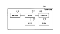
- FIG. 5 is a block diagram of the power management apparatus 200.
- the power management apparatus 200 includes a wireless communication unit 210, a wired communication unit 220, a storage unit 230, a power supply unit 240, and a control unit 250.
- the wireless communication unit 210 is a block for establishing a wireless connection with the relay device 400.
- the wireless communication unit 210 is a WLAN wireless communication unit compliant with the WLAN communication standard.
- the power management apparatus 200 may include a Wi-SUN wireless communication unit in addition to the wireless communication unit 210 (WLAN wireless communication unit).
- the wired communication unit 220 is a block used for wired communication with devices in the customer facility 20. In the first embodiment, the wired communication unit 220 may be unnecessary.
- the storage unit 230 is a block that stores information and programs used for control in the power management apparatus 200.
- the storage unit 430 includes a nonvolatile storage medium and a volatile storage medium.
- the storage unit 230 (nonvolatile storage medium) stores second authentication information used for authentication processing with the smart meter 300 in advance.
- the second authentication information includes an authentication method and an authentication key.
- the second authentication information is the same authentication information as the authentication information used for the authentication process when the power management apparatus 200 establishes a wireless connection with the smart meter 300.
- the second authentication information may be authentication information different from authentication information used for authentication processing when the power management apparatus 200 establishes a wireless connection with the smart meter 300.
- the power supply unit 240 is a block for supplying power to other blocks in the power management apparatus 200.
- the power supply unit 240 is configured by an AC power supply (AC adapter), a battery, or a combination thereof.
- the control unit 250 is a block that performs various controls by executing a program stored in the storage unit 230.
- the control unit 250 includes at least one processor.
- the control unit 250 controls the wireless communication unit 210 and the wired communication unit 220.
- the control unit 250 performs an authentication process (first authentication process) with the relay apparatus 400, and establishes a wireless connection with the relay apparatus 400 when the authentication process with the relay apparatus 400 is successful.
- the control unit 250 notifies the relay device 400 of the second authentication information after establishing a wireless connection with the relay device 400.
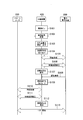
- FIG. 6 is an operation sequence diagram of the power management system 10.
- step S101 when the user turns on the power switch 450C, power is supplied to the relay device 400.
- step S102 the relay device 400 automatically starts searching for a radio signal emitted from the smart meter 300.
- relay device 400 automatically starts searching for a radio signal emitted from power management device 200.
- step S103 the relay device 400 measures the first signal quality of the radio signal from the smart meter 300 and displays the first signal quality.
- relay device 400 measures the second signal quality of the radio signal from power management device 200 and displays the second signal quality.
- step S104 the relay device 400 receives from the user a connection operation (second connection operation) instructing to establish a wireless connection with the power management device 200.
- step S104 is not essential. That is, the relay apparatus 400 may attempt to establish a wireless connection with the power management apparatus 200 even when there is no user connection operation. The relay device 400 may transition to a state of waiting for a user connection operation only when the wireless connection with the power management device 200 has failed to be established. As a result, the connection sequence can be further automated.
- step S105 the relay apparatus 400 performs an authentication process (first authentication process) with the power management apparatus 200 using the first authentication information incorporated in the relay apparatus 400 in advance.
- step S106 when the authentication process with the power management apparatus 200 is successful, the relay apparatus 400 establishes a wireless connection with the power management apparatus 200.
- the relay apparatus 400 may perform key exchange with the power management apparatus 200.
- the relay device 400 exchanges an encryption key applied to wireless communication with the power management device 200 with the power management device 200.
- step S107 the relay device 400 presents to the user a notification indicating that the wireless connection with the smart meter 300 has been established.
- step S108 the power management apparatus 200 notifies the relay apparatus 400 of the second authentication information.
- the relay device 400 acquires the second authentication process.
- step S109 the relay device 400 receives a connection operation (first connection operation) instructing to establish a wireless connection with the smart meter 300 from the user.
- step S109 is not essential.
- the relay device 400 may attempt to establish a wireless connection with the smart meter 300 without a user connection operation.
- the relay device 400 may transition to a state of waiting for a user connection operation only when the wireless connection with the smart meter 300 has failed to be established. As a result, the connection sequence can be further automated.
- step S110 the relay apparatus 400 performs an authentication process (second authentication process) with the smart meter 300 using the second authentication information acquired from the power management apparatus 200.
- step S111 when the authentication process with the smart meter 300 is successful, the relay device 400 establishes a wireless connection with the smart meter 300.
- the relay device 400 may perform key exchange with the smart meter 300. Specifically, the relay device 400 exchanges an encryption key applied to wireless communication with the smart meter 300 with the smart meter 300.
- step S112 the relay device 400 presents a notification to the user indicating that the wireless connection with the smart meter 300 has been established.
- step S104 and step S109 may be combined into one step. Specifically, step S104 is omitted, and the user is collectively notified in step S109 that the wireless connection with the power management apparatus 200 has been established and the wireless connection with the smart meter 300 has been established. Also good.
- step S113 the relay device 400 relays communication (one-to-one communication) between the smart meter 300 and the power management device 200.
- ECHONET Lite is applied as a communication protocol between the smart meter 300 and the power management apparatus 200.
- the user can grasp the signal quality on the power management device 200 side and the signal quality on the smart meter 300 side based on the display of the relay device 400.
- the relay apparatus 400 can be installed at an appropriate position, and the quality of communication between the smart meter 300 and the power management apparatus 200 can be improved.
- the power management apparatus 200 performs control to measure the signal quality of the radio signal (WLAN radio signal) from the relay apparatus 400 and present the signal quality to the user.
- the power management apparatus 200 may perform the presentation in a state where the wireless connection with the relay apparatus 400 is not established, or may perform the presentation after the wireless connection with the relay apparatus 400 is established.
- the power management apparatus 200 displays the measured signal quality on the display device 290, for example. Thereby, the user can grasp
- the power management apparatus 200 has a connection state with the relay apparatus 400 when the connection state with the relay apparatus 400 deteriorates after the wireless connection with the relay apparatus 400 is established. Control is performed to present a warning to the user indicating the deterioration.
- the power management apparatus 200 causes the display device 290 to display the warning. Thereby, the user can grasp that the connection state between the power management apparatus 200 and the relay apparatus 400 has deteriorated.
- the relay apparatus 400 includes a first operation unit (a connection button 450A) that receives a first connection operation that instructs to establish a wireless connection with the smart meter 300 from the user, and the power management apparatus 200. And a second operation unit (connection button 450B) for accepting a second connection operation for instructing establishment of a wireless connection from the user.
- a connection button 450A receives a first connection operation that instructs to establish a wireless connection with the smart meter 300 from the user
- connection button 450B for accepting a second connection operation for instructing establishment of a wireless connection from the user.
- FIG. 7 is a diagram illustrating an implementation example of the relay device 400 according to the second embodiment.
- the relay device 400 does not have the connection button 450A and the connection button 450B as the operation unit 450, but has a power switch 450C.
- the power switch 450C also functions as the connection button 450A and the connection button 450B.
- the control unit 470 when the power switch 450C is turned on, the control unit 470 performs a connection operation for instructing to establish both a wireless connection with the smart meter 300 and a wireless connection with the power management apparatus 200 from the user. Considered accepted. Then, the control unit 470 performs control to establish both the wireless connection with the smart meter 300 and the wireless connection with the power management apparatus 200. Specifically, in the second embodiment, step S104 and step S109 shown in FIG. 6 are always omitted.
- a collective connection button may be provided as the operation unit 450.
- the collective connection button accepts a connection operation (collective connection operation) for instructing to establish both a wireless connection with the smart meter 300 and a wireless connection with the power management apparatus 200 from the user.
- the control unit 470 performs control to establish both the wireless connection with the smart meter 300 and the wireless connection with the power management apparatus 200 according to the collective connection operation.
- the convenience of the user when installing the relay device 400 can be enhanced by automating the connection sequence.
- connection between the relay apparatus 400 and the power management apparatus 200 is not a wireless connection but a wired connection.
- FIG. 8 is a block diagram of the relay device 400 according to the third embodiment. As illustrated in FIG. 8, the relay device 400 includes a wired communication unit 480 instead of the second wireless communication unit 420 illustrated in FIG. 3.
- the wired communication unit 480 is a block that performs wired communication with the wired communication unit 220 of the power management apparatus 200.
- the wired communication unit 480 is connected to the wired communication unit 220 of the power management apparatus 200 via a physical cable.
- the second display portion 410B and the connection button 450B shown in FIG. 4 can be dispensed with.
- the connection sequence between the relay apparatus 400 and the power management apparatus 200 can be made unnecessary.
- connection between the relay apparatus 400 and the power management apparatus 200 is a wired connection
- connection between the relay apparatus 400 and the smart meter 300 may be a wired connection.
- the communication standard used for wireless communication between the smart meter 300 and the relay device 400 and the wireless communication between the power management device 200 and the relay device 400 are used.
- the case where the communication standard is different was assumed.
- the same communication standard for example, Wi-SUN communication standard
- Wi-SUN communication standard may be applied between the smart meter 300 and the relay apparatus 400 and between the power management apparatus 200 and the relay apparatus 400.
- the customer facility 20 is a house and the power management apparatus 200 is a HEMS has been described.
- the customer facility 20 may be a facility (for example, a building, a factory, a store, etc.) different from a house.
- the power management apparatus 200 may be BEMS (Building Energy Management System), FEMS (Factor Energy Management System), SEMS (Store Energy Management System), or the like.
- the relay apparatus 400 may transmit a message indicating that a wireless connection has been established to the power management apparatus 200 after establishing wireless communication with the power management apparatus 200 and the smart meter 300.
- the power management apparatus 200 can display a display indicating that the wireless connection has been established on the display device. Thereby, the convenience for the consumer can be improved. If the wireless connection is interrupted, this can be displayed on the display device.
- the present invention it is possible to provide a power management system, a relay device, and a power management method that enable appropriate communication between a smart meter and a power management device.
Landscapes
- Engineering & Computer Science (AREA)
- Computer Networks & Wireless Communication (AREA)
- Signal Processing (AREA)
- Business, Economics & Management (AREA)
- Accounting & Taxation (AREA)
- Physics & Mathematics (AREA)
- Electromagnetism (AREA)
- Selective Calling Equipment (AREA)
- Remote Monitoring And Control Of Power-Distribution Networks (AREA)
- Radio Relay Systems (AREA)
Abstract
Priority Applications (2)
| Application Number | Priority Date | Filing Date | Title |
|---|---|---|---|
| US15/535,342 US20170331570A1 (en) | 2014-12-25 | 2015-12-22 | Power management system, relay apparatus, and power management method |
| JP2016566386A JP6441962B2 (ja) | 2014-12-25 | 2015-12-22 | 電力管理システム、中継装置及び電力管理方法 |
Applications Claiming Priority (4)
| Application Number | Priority Date | Filing Date | Title |
|---|---|---|---|
| JP2014-261788 | 2014-12-25 | ||
| JP2014261788 | 2014-12-25 | ||
| JP2014261794 | 2014-12-25 | ||
| JP2014-261794 | 2014-12-25 |
Publications (1)
| Publication Number | Publication Date |
|---|---|
| WO2016104501A1 true WO2016104501A1 (fr) | 2016-06-30 |
Family
ID=56150518
Family Applications (1)
| Application Number | Title | Priority Date | Filing Date |
|---|---|---|---|
| PCT/JP2015/085828 Ceased WO2016104501A1 (fr) | 2014-12-25 | 2015-12-22 | Système de gestion d'énergie électrique, dispositif de relais et procédé de gestion d'énergie électrique |
Country Status (3)
| Country | Link |
|---|---|
| US (1) | US20170331570A1 (fr) |
| JP (1) | JP6441962B2 (fr) |
| WO (1) | WO2016104501A1 (fr) |
Cited By (9)
| Publication number | Priority date | Publication date | Assignee | Title |
|---|---|---|---|---|
| JP2017050970A (ja) * | 2015-09-01 | 2017-03-09 | パナソニックIpマネジメント株式会社 | 中継装置及びエネルギマネジメントシステム |
| KR20180109489A (ko) * | 2017-03-28 | 2018-10-08 | 주식회사 코어라인 | Wi-SUN망을 통해 구역조명과 개별 조명을 선택제어하는 스마트 무선조명모듈제어장치 및 방법 |
| JP2019009698A (ja) * | 2017-06-27 | 2019-01-17 | 株式会社長谷工コーポレーション | 屋内無線システムとその設置方法 |
| DE102017007449A1 (de) * | 2017-08-07 | 2019-02-07 | Christoph Lotter | NB-loT Messgerät für Installationsbetriebe |
| JP2019106599A (ja) * | 2017-12-11 | 2019-06-27 | 河村電器産業株式会社 | スマートメータ通信装置 |
| EP3496286A4 (fr) * | 2016-08-05 | 2019-07-17 | Panasonic Intellectual Property Management Co., Ltd. | Dispositif de communication, et système de communication |
| JP2020092542A (ja) * | 2018-12-06 | 2020-06-11 | 河村電器産業株式会社 | Bルート通信アダプタ |
| JP2021158595A (ja) * | 2020-03-27 | 2021-10-07 | 東京瓦斯株式会社 | 電波中継器の設置方法、補助装置 |
| JP2024002288A (ja) * | 2022-06-23 | 2024-01-11 | 株式会社東芝 | 遠隔伝送システム、監視局および回線監視方法 |
Families Citing this family (1)
| Publication number | Priority date | Publication date | Assignee | Title |
|---|---|---|---|---|
| TWI746083B (zh) * | 2020-07-24 | 2021-11-11 | 聯陽半導體股份有限公司 | 訊號中繼系統 |
Citations (5)
| Publication number | Priority date | Publication date | Assignee | Title |
|---|---|---|---|---|
| JP2002141910A (ja) * | 2000-10-31 | 2002-05-17 | Fujitsu I-Network Systems Ltd | Lan回線状態表示装置 |
| JP2006100884A (ja) * | 2004-09-28 | 2006-04-13 | Saxa Inc | ベストポジション検索機能付中継機 |
| JP2012156671A (ja) * | 2011-01-25 | 2012-08-16 | Nec Corp | 電波状態表示システム、ユーザ端末、ルーター、電波状態表示方法およびプログラム |
| JP2014068190A (ja) * | 2012-09-26 | 2014-04-17 | Softbank Bb Corp | 中継装置及びプログラム |
| JP2014187839A (ja) * | 2013-03-25 | 2014-10-02 | Sharp Corp | 電力管理装置および電力管理システム |
Family Cites Families (4)
| Publication number | Priority date | Publication date | Assignee | Title |
|---|---|---|---|---|
| US20110004406A1 (en) * | 2009-03-31 | 2011-01-06 | Gridpoint, Inc. | Systems and methods for location determination of devices using network fingerprints for power management |
| US9190844B2 (en) * | 2012-11-04 | 2015-11-17 | Bao Tran | Systems and methods for reducing energy usage |
| US8570999B1 (en) * | 2011-01-19 | 2013-10-29 | Greenvity Communications, Inc. | System and method for communications in a network |
| JP5851025B2 (ja) * | 2012-05-14 | 2016-02-03 | 株式会社日立製作所 | 無線基地局、無線通信ネットワークシステム、及び通信制御方法 |
-
2015
- 2015-12-22 JP JP2016566386A patent/JP6441962B2/ja active Active
- 2015-12-22 US US15/535,342 patent/US20170331570A1/en not_active Abandoned
- 2015-12-22 WO PCT/JP2015/085828 patent/WO2016104501A1/fr not_active Ceased
Patent Citations (5)
| Publication number | Priority date | Publication date | Assignee | Title |
|---|---|---|---|---|
| JP2002141910A (ja) * | 2000-10-31 | 2002-05-17 | Fujitsu I-Network Systems Ltd | Lan回線状態表示装置 |
| JP2006100884A (ja) * | 2004-09-28 | 2006-04-13 | Saxa Inc | ベストポジション検索機能付中継機 |
| JP2012156671A (ja) * | 2011-01-25 | 2012-08-16 | Nec Corp | 電波状態表示システム、ユーザ端末、ルーター、電波状態表示方法およびプログラム |
| JP2014068190A (ja) * | 2012-09-26 | 2014-04-17 | Softbank Bb Corp | 中継装置及びプログラム |
| JP2014187839A (ja) * | 2013-03-25 | 2014-10-02 | Sharp Corp | 電力管理装置および電力管理システム |
Non-Patent Citations (2)
| Title |
|---|
| "Display Menu no Tsukaikata Aterm MR03LN User's Manual Ver.3.02", NEC PLATFORMS, LTD., 13 October 2014 (2014-10-13), Retrieved from the Internet <URL:http://web.archive.org/web/20141013043446/http://www.aterm.jp/function/mr03ln/guide/displaymenu.html> [retrieved on 20160215] * |
| "TR-1052 HEMS-Smart Meter (B Route) Tsushin Interface Jisso Shosai Guideline 1.0 edition", THE TELECOMMUNICATION TECHNOLOGY COMMITTEE, 17 March 2014 (2014-03-17), pages 31, Retrieved from the Internet <URL:http://www.ttc.or.jp/jp/document_list/pdf/j/TR/TR-1052v1.pdf> [retrieved on 20160215] * |
Cited By (15)
| Publication number | Priority date | Publication date | Assignee | Title |
|---|---|---|---|---|
| JP2017050970A (ja) * | 2015-09-01 | 2017-03-09 | パナソニックIpマネジメント株式会社 | 中継装置及びエネルギマネジメントシステム |
| EP3496286A4 (fr) * | 2016-08-05 | 2019-07-17 | Panasonic Intellectual Property Management Co., Ltd. | Dispositif de communication, et système de communication |
| KR20180109489A (ko) * | 2017-03-28 | 2018-10-08 | 주식회사 코어라인 | Wi-SUN망을 통해 구역조명과 개별 조명을 선택제어하는 스마트 무선조명모듈제어장치 및 방법 |
| KR101951395B1 (ko) * | 2017-03-28 | 2019-02-22 | 주식회사 코어라인 | Wi-SUN망을 통해 구역조명과 개별 조명을 선택제어하는 스마트 무선조명모듈제어장치 및 방법 |
| JP2019009698A (ja) * | 2017-06-27 | 2019-01-17 | 株式会社長谷工コーポレーション | 屋内無線システムとその設置方法 |
| DE102017007449A1 (de) * | 2017-08-07 | 2019-02-07 | Christoph Lotter | NB-loT Messgerät für Installationsbetriebe |
| JP2019106599A (ja) * | 2017-12-11 | 2019-06-27 | 河村電器産業株式会社 | スマートメータ通信装置 |
| JP7043239B2 (ja) | 2017-12-11 | 2022-03-29 | 河村電器産業株式会社 | スマートメータ通信装置 |
| JP2020092542A (ja) * | 2018-12-06 | 2020-06-11 | 河村電器産業株式会社 | Bルート通信アダプタ |
| JP2021158595A (ja) * | 2020-03-27 | 2021-10-07 | 東京瓦斯株式会社 | 電波中継器の設置方法、補助装置 |
| JP2023164530A (ja) * | 2020-03-27 | 2023-11-10 | 東京瓦斯株式会社 | 補助装置 |
| JP7462454B2 (ja) | 2020-03-27 | 2024-04-05 | 東京瓦斯株式会社 | 電波中継器の設置方法、補助装置 |
| JP7673138B2 (ja) | 2020-03-27 | 2025-05-08 | 東京瓦斯株式会社 | 補助装置 |
| JP2024002288A (ja) * | 2022-06-23 | 2024-01-11 | 株式会社東芝 | 遠隔伝送システム、監視局および回線監視方法 |
| JP7867876B2 (ja) | 2022-06-23 | 2026-06-01 | 株式会社東芝 | 遠隔伝送システム、監視局および回線監視方法 |
Also Published As
| Publication number | Publication date |
|---|---|
| JPWO2016104501A1 (ja) | 2017-09-14 |
| US20170331570A1 (en) | 2017-11-16 |
| JP6441962B2 (ja) | 2018-12-19 |
Similar Documents
| Publication | Publication Date | Title |
|---|---|---|
| JP6441962B2 (ja) | 電力管理システム、中継装置及び電力管理方法 | |
| US12212968B2 (en) | Secure communication for commissioning and decommissioning circuit breakers and panel system | |
| JP2011511606A (ja) | 通信インターフェースを持つユーティリティ切断監視ノード | |
| JP6715448B2 (ja) | 出力制御装置、電力管理装置及び電力管理方法 | |
| JP2013115885A (ja) | 電力需要制御システム、方法及び電源コンセント装置 | |
| EP3183706B1 (fr) | Système et procédé de commande de fourniture d'énergie électrique | |
| JP2023091045A (ja) | 家電システム及び家電機器 | |
| US10031496B2 (en) | Control system, control apparatus, information equipment, and control method | |
| CN104577548B (zh) | 智能插座 | |
| CN105074715A (zh) | 消费者设施设备、控制装置和控制方法 | |
| JPWO2015115572A1 (ja) | 操作装置及び操作方法 | |
| KR101224222B1 (ko) | 전기 자동차용 충전 장치 및 그를 이용한 충전 시스템 | |
| US10084610B2 (en) | Control apparatus and control method | |
| JP6851008B2 (ja) | 機器管理装置 | |
| KR101427540B1 (ko) | 원격 전원 및 대기전력 관리 시스템 및 방법 | |
| JP2013187848A (ja) | 通信システムおよび通信装置 | |
| JP2012175688A (ja) | 遠隔検針システム | |
| US20140192679A1 (en) | Convergent Network Node with the Automatic Reconfiguration Capability | |
| JP2013016950A (ja) | 遠隔検針システム | |
| US10754315B2 (en) | Management system and management method for transmitting a command including a code value for controlling an apparatus | |
| JP6348087B2 (ja) | 端末網制御装置 | |
| JP2016072801A (ja) | 通信監視装置及び通信監視システム | |
| HK40060490B (en) | A system and method for monitoring residential energy consumption | |
| KR20140029997A (ko) | 전기제품 | |
| JP2018064135A (ja) | 電力情報収集システム |
Legal Events
| Date | Code | Title | Description |
|---|---|---|---|
| 121 | Ep: the epo has been informed by wipo that ep was designated in this application |
Ref document number: 15873069 Country of ref document: EP Kind code of ref document: A1 |
|
| ENP | Entry into the national phase |
Ref document number: 2016566386 Country of ref document: JP Kind code of ref document: A |
|
| WWE | Wipo information: entry into national phase |
Ref document number: 15535342 Country of ref document: US |
|
| NENP | Non-entry into the national phase |
Ref country code: DE |
|
| 122 | Ep: pct application non-entry in european phase |
Ref document number: 15873069 Country of ref document: EP Kind code of ref document: A1 |