WO2016104556A1 - Unité de palier de turbine à air - Google Patents
Unité de palier de turbine à air Download PDFInfo
- Publication number
- WO2016104556A1 WO2016104556A1 PCT/JP2015/085921 JP2015085921W WO2016104556A1 WO 2016104556 A1 WO2016104556 A1 WO 2016104556A1 JP 2015085921 W JP2015085921 W JP 2015085921W WO 2016104556 A1 WO2016104556 A1 WO 2016104556A1
- Authority
- WO
- WIPO (PCT)
- Prior art keywords
- seal member
- peripheral surface
- ring
- bearing unit
- inner ring
- Prior art date
- Legal status (The legal status is an assumption and is not a legal conclusion. Google has not performed a legal analysis and makes no representation as to the accuracy of the status listed.)
- Ceased
Links
Images











Classifications
-
- A—HUMAN NECESSITIES
- A61—MEDICAL OR VETERINARY SCIENCE; HYGIENE
- A61C—DENTISTRY; APPARATUS OR METHODS FOR ORAL OR DENTAL HYGIENE
- A61C1/00—Dental machines for boring or cutting ; General features of dental machines or apparatus, e.g. hand-piece design
- A61C1/08—Machine parts specially adapted for dentistry
- A61C1/18—Flexible shafts; Clutches or the like; Bearings or lubricating arrangements; Drives or transmissions
- A61C1/181—Bearings or lubricating arrangements, e.g. air-cushion bearings
-
- A—HUMAN NECESSITIES
- A61—MEDICAL OR VETERINARY SCIENCE; HYGIENE
- A61C—DENTISTRY; APPARATUS OR METHODS FOR ORAL OR DENTAL HYGIENE
- A61C1/00—Dental machines for boring or cutting ; General features of dental machines or apparatus, e.g. hand-piece design
- A61C1/02—Dental machines for boring or cutting ; General features of dental machines or apparatus, e.g. hand-piece design characterised by the drive of the dental tools
- A61C1/05—Dental machines for boring or cutting ; General features of dental machines or apparatus, e.g. hand-piece design characterised by the drive of the dental tools with turbine drive
-
- F—MECHANICAL ENGINEERING; LIGHTING; HEATING; WEAPONS; BLASTING
- F16—ENGINEERING ELEMENTS AND UNITS; GENERAL MEASURES FOR PRODUCING AND MAINTAINING EFFECTIVE FUNCTIONING OF MACHINES OR INSTALLATIONS; THERMAL INSULATION IN GENERAL
- F16C—SHAFTS; FLEXIBLE SHAFTS; ELEMENTS OR CRANKSHAFT MECHANISMS; ROTARY BODIES OTHER THAN GEARING ELEMENTS; BEARINGS
- F16C33/00—Parts of bearings; Special methods for making bearings or parts thereof
- F16C33/72—Sealings
- F16C33/76—Sealings of ball or roller bearings
- F16C33/78—Sealings of ball or roller bearings with a diaphragm, disc, or ring, with or without resilient members
- F16C33/7816—Details of the sealing or parts thereof, e.g. geometry, material
- F16C33/782—Details of the sealing or parts thereof, e.g. geometry, material of the sealing region
- F16C33/7823—Details of the sealing or parts thereof, e.g. geometry, material of the sealing region of sealing lips
-
- F—MECHANICAL ENGINEERING; LIGHTING; HEATING; WEAPONS; BLASTING
- F16—ENGINEERING ELEMENTS AND UNITS; GENERAL MEASURES FOR PRODUCING AND MAINTAINING EFFECTIVE FUNCTIONING OF MACHINES OR INSTALLATIONS; THERMAL INSULATION IN GENERAL
- F16C—SHAFTS; FLEXIBLE SHAFTS; ELEMENTS OR CRANKSHAFT MECHANISMS; ROTARY BODIES OTHER THAN GEARING ELEMENTS; BEARINGS
- F16C33/00—Parts of bearings; Special methods for making bearings or parts thereof
- F16C33/72—Sealings
- F16C33/76—Sealings of ball or roller bearings
- F16C33/78—Sealings of ball or roller bearings with a diaphragm, disc, or ring, with or without resilient members
- F16C33/784—Sealings of ball or roller bearings with a diaphragm, disc, or ring, with or without resilient members mounted to a groove in the inner surface of the outer race and extending toward the inner race
- F16C33/7843—Sealings of ball or roller bearings with a diaphragm, disc, or ring, with or without resilient members mounted to a groove in the inner surface of the outer race and extending toward the inner race with a single annular sealing disc
- F16C33/7853—Sealings of ball or roller bearings with a diaphragm, disc, or ring, with or without resilient members mounted to a groove in the inner surface of the outer race and extending toward the inner race with a single annular sealing disc with one or more sealing lips to contact the inner race
- F16C33/7856—Sealings of ball or roller bearings with a diaphragm, disc, or ring, with or without resilient members mounted to a groove in the inner surface of the outer race and extending toward the inner race with a single annular sealing disc with one or more sealing lips to contact the inner race with a single sealing lip
-
- F—MECHANICAL ENGINEERING; LIGHTING; HEATING; WEAPONS; BLASTING
- F16—ENGINEERING ELEMENTS AND UNITS; GENERAL MEASURES FOR PRODUCING AND MAINTAINING EFFECTIVE FUNCTIONING OF MACHINES OR INSTALLATIONS; THERMAL INSULATION IN GENERAL
- F16C—SHAFTS; FLEXIBLE SHAFTS; ELEMENTS OR CRANKSHAFT MECHANISMS; ROTARY BODIES OTHER THAN GEARING ELEMENTS; BEARINGS
- F16C41/00—Other accessories, e.g. devices integrated in the bearing not relating to the bearing function as such
- F16C41/001—Integrated brakes or clutches for stopping or coupling the relatively movable parts
-
- F—MECHANICAL ENGINEERING; LIGHTING; HEATING; WEAPONS; BLASTING
- F16—ENGINEERING ELEMENTS AND UNITS; GENERAL MEASURES FOR PRODUCING AND MAINTAINING EFFECTIVE FUNCTIONING OF MACHINES OR INSTALLATIONS; THERMAL INSULATION IN GENERAL
- F16C—SHAFTS; FLEXIBLE SHAFTS; ELEMENTS OR CRANKSHAFT MECHANISMS; ROTARY BODIES OTHER THAN GEARING ELEMENTS; BEARINGS
- F16C19/00—Bearings with rolling contact, for exclusively rotary movement
- F16C19/02—Bearings with rolling contact, for exclusively rotary movement with bearing balls essentially of the same size in one or more circular rows
- F16C19/04—Bearings with rolling contact, for exclusively rotary movement with bearing balls essentially of the same size in one or more circular rows for radial load mainly
- F16C19/06—Bearings with rolling contact, for exclusively rotary movement with bearing balls essentially of the same size in one or more circular rows for radial load mainly with a single row or balls
-
- F—MECHANICAL ENGINEERING; LIGHTING; HEATING; WEAPONS; BLASTING
- F16—ENGINEERING ELEMENTS AND UNITS; GENERAL MEASURES FOR PRODUCING AND MAINTAINING EFFECTIVE FUNCTIONING OF MACHINES OR INSTALLATIONS; THERMAL INSULATION IN GENERAL
- F16C—SHAFTS; FLEXIBLE SHAFTS; ELEMENTS OR CRANKSHAFT MECHANISMS; ROTARY BODIES OTHER THAN GEARING ELEMENTS; BEARINGS
- F16C19/00—Bearings with rolling contact, for exclusively rotary movement
- F16C19/54—Systems consisting of a plurality of bearings with rolling friction
-
- F—MECHANICAL ENGINEERING; LIGHTING; HEATING; WEAPONS; BLASTING
- F16—ENGINEERING ELEMENTS AND UNITS; GENERAL MEASURES FOR PRODUCING AND MAINTAINING EFFECTIVE FUNCTIONING OF MACHINES OR INSTALLATIONS; THERMAL INSULATION IN GENERAL
- F16C—SHAFTS; FLEXIBLE SHAFTS; ELEMENTS OR CRANKSHAFT MECHANISMS; ROTARY BODIES OTHER THAN GEARING ELEMENTS; BEARINGS
- F16C2316/00—Apparatus in health or amusement
- F16C2316/10—Apparatus in health or amusement in medical appliances, e.g. in diagnosis, dentistry, instruments, prostheses, medical imaging appliances
- F16C2316/13—Dental machines
Definitions
- the present invention relates to a bearing unit for an air turbine.
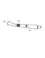
- the dental air turbine handpiece 120 includes a grip part 121 and a head part 122 provided at the tip of the grip part 121.
- the surgeon holds the grip portion 121 and performs, for example, tooth cutting.
- a dental air turbine bearing unit 100 constituting the head portion 122 a rotary shaft 101 to which a dental treatment tool (not shown) is attached at one end and the rotary shaft 101 are rotationally driven by compressed air.
- a turbine blade 102 and a pair of ball bearings 103 and 104 that rotatably support a rotating shaft 101 are known.
- the rotary shaft 101, the turbine blade 102, and the pair of ball bearings 103 and 104 are disposed in the head housing 105.
- the outer rings 106 and 107 of the pair of ball bearings 103 and 104 are supported via rubber rings 108 attached to the annular recesses 109 and 110 of the head housing 105.
- the outer ring 107 of the lower ball bearing 104 is biased upward by a spring washer 111 to apply a preload to the pair of ball bearings 103 and 104. That is, the pair of ball bearings 103 and 104 that support the rotating shaft 101 are combined in front and are given a constant pressure preload by the elastic force of the spring washer 111.
- Patent Document 1 discloses a head housing having an air supply port, a rotary shaft that is rotatably housed inside the head housing and has a blade that receives air supplied from the air supply port, and the rotary shaft inside the head housing.
- a dental or medical air turbine handpiece is disclosed which includes a ball bearing that is rotatably supported up and down across an air supply port.
- a heat-resistant mechanical seal is provided on the side close to the air supply port of the ball bearing.
- the heat-resistant mechanical seal is elastically deformed so as to come into contact with the ball bearing and shields it when the pressure of the supply air is acting on the supply port, that is, when the blade is rotating.
- the pressure of the supply air is stopped, that is, when the rotation of the blade is stopped, the original state is restored so as to be in non-contact with the ball bearing.
- the friction resistance between the heat-resistant mechanical seal and the blade is eliminated when the blade of the rotating shaft is activated by making the heat-resistant mechanical seal and the ball bearing in a non-contact state. Is trying to start smoothly.
- Air turbine handpieces as described above rotate at a very high speed when in use.
- an immediate stop is required to shorten the time for treatment and the like. It is done.
- the present invention has been made in view of the above-described problems, and an object thereof is to provide an air turbine bearing unit capable of quickly stopping the rotation.
- An air turbine bearing unit comprising: The rolling bearing includes an outer ring fixed to the housing, an inner ring fixed to the rotating shaft, a plurality of rolling elements arranged to roll between the outer ring and the inner ring, and an inner periphery of the outer ring.
- a seal member fixed to a surface and sealing a space between the outer ring and the inner ring, When the compressed air does not act, the seal member contacts the outer peripheral surface of the inner ring, A bearing unit for an air turbine, wherein the contact area between the seal member and the outer peripheral surface of the inner ring is smaller when the compressed air acts than when the compressed air does not act.
- the seal member has a lip portion that can contact an outer peripheral surface of the inner ring and is elastically deformable.
- the said lip part is a shape which inclines in the supply direction of the said compressed air as it goes to radial inside,
- the bearing unit for air turbines as described in (1) characterized by the above-mentioned.
- the seal member has a lip portion that can contact an outer peripheral surface of the inner ring and is elastically deformable.
- the air lip bearing unit according to (1) wherein the lip portion is inclined outward in the axial direction as it goes radially inward from the metal core or base of the seal member.
- the air turbine bearing unit according to any one of (1) to (3) wherein at least a portion of the outer peripheral surface of the inner ring that is in contact with the seal member is a flat surface.
- a groove for fixing the seal member is formed on the inner peripheral surface of the outer ring,
- the air turbine bearing according to any one of (1) to (4) wherein a base portion made of an elastic material at a radially outer end portion of the seal member is fixed to the groove portion by a retaining ring.
- a groove for fixing the seal member is formed on the inner peripheral surface of the outer ring, The air turbine bearing according to any one of (1) to (4), wherein a base portion made of an elastic material at a radially outer end portion of the seal member is caulked and fixed to the groove portion. unit. (7) A groove portion for fixing the seal member is formed on the inner peripheral surface of the outer ring, Any one of (1) to (4), wherein a base portion made of an elastic material at a radially outer end portion of the seal member is sandwiched and fixed by both axial surfaces of the groove portion. Air turbine bearing unit.
- a groove portion for fixing the seal member is formed on the inner peripheral surface of the outer ring,
- a groove portion for fixing the seal member is formed on the inner peripheral surface of the outer ring,
- the groove portion has a tapered surface that inclines radially outward as it goes inward in the axial direction, and an axially inner side surface that extends radially inward from the axially inner end of the tapered surface, (1) to (4), wherein a base portion made of a metal material at a radially outer end portion of the seal member is fixed to the groove portion by contacting the tapered surface and the axially inner side surface.
- the inner ring extends to the outer side in the axial direction than the outer ring,
- (11) The air turbine according to any one of (1) to (10), wherein when the compressed air acts, the seal member is in a non-contact state with the outer peripheral surface of the inner ring. Bearing unit. (12) When the compressed air does not act, the contact area where the inner peripheral surface of the seal member contacts the outer peripheral surface of the inner ring is 10% or more of the entire inner peripheral surface of the seal member.
- the bearing unit for an air turbine according to any one of (1) to (11).
- the compressed air when the supply of compressed air is stopped to stop the operation, the compressed air does not act on the seal member, so compared with the case where the compressed air acts (during operation).
- the contact area between the seal member and the outer peripheral surface of the inner ring is increased. Therefore, the seal member acts as a brake for the rotating shaft, and the rotating shaft can be quickly stopped.
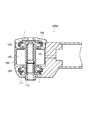
- FIG. 1 shows an air turbine bearing unit of the present embodiment
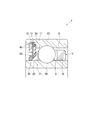
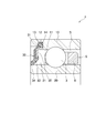
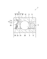
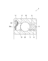
- FIG. 2 shows a rolling bearing 1 constituting the air turbine bearing unit of the present embodiment
- an air turbine bearing unit 100 ⁇ / b> A has a turbine blade 102 that rotates by receiving compressed air, and the turbine blade 102 is integrally fixed, and a tool (for example, a dental treatment tool) can be attached to one end.
- a rotating shaft 101 and a rolling bearing 1 that rotatably supports the rotating shaft 101 with respect to the housing 105 are provided. Therefore, in the rolling bearing 1 shown in FIG. 2, compressed air is supplied from the right to the left when the handpiece is driven.
- the air turbine bearing unit of the present embodiment differs from the conventional configuration shown in FIG.
- the air turbine bearing unit is not limited to the configuration shown in FIG.
- the rolling bearing 1 includes an outer ring 10 fixed to the housing 105, an inner ring 20 fixed to the rotating shaft 101, and a plurality of balls (rolling elements) 3 that are arranged to freely roll between the outer ring 10 and the inner ring 20. And cages 5 for holding the balls 3 respectively.
- the retainer 5 is a so-called crown-shaped retainer, and the substantially annular rim portion 6 is located upstream of the balls 3 in the compressed air supply direction (right side in the figure).
- a groove 12 for fixing the seal member 30 is formed on the downstream side in the compressed air supply direction (left side in the figure) with respect to the ball 3.
- the seal member 30 is not limited to the configuration arranged downstream of the balls 3 in the compressed air supply direction as in the present embodiment as long as a brake function described later is exhibited. May be arranged on the upstream side in the supply direction (right side in the figure), or one pair may be arranged on both the downstream side and the upstream side in the supply direction of compressed air rather than the balls 3.
- the sealing member 30 has a base portion 31 made of an elastic material extending in the radial direction and a lip portion 33 made of an elastic material formed integrally with the base portion 31.
- the base 31 covers the cored bar 35 at its radially inner portion, and the shape and strength are maintained. Further, the base 31 is inserted into the groove 12 and fixed while contacting the retaining ring 40.
- the retaining ring 40 uses a C-ring retaining ring, but an annular retaining ring or the like may be used.
- the lip portion 33 has a substantially annular shape that inclines in the compressed air supply direction (in the direction from right to left in FIG. 2) as it goes radially inward, and abuts against the outer peripheral surface 21 of the inner ring 20. It is possible. That is, the lip portion 33 is inclined outward in the axial direction from the cored bar 35 toward the inner side in the radial direction.
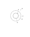
- the inner peripheral surface 34 of the lip portion 33 has a substantially annular shape (substantially circular shape in cross section), that is, the seal inner diameter has a substantially annular shape.
- the inner peripheral surface 34 of the lip portion 33 that is the seal inner diameter is the entire area. Of these, in an area of almost 100%, it is possible to contact the outer peripheral surface 21 of the inner ring 20, that is, almost complete contact.
- the seal member 30 seals the bearing internal space S between the inner peripheral surface 11 of the outer ring 10 and the outer peripheral surface 21 of the inner ring 20.
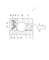
- the compressed air when the compressed air is supplied to the turbine blade to drive the dental air turbine handpiece, the compressed air flows from the right side to the left side in the bearing inner space S as shown by an arrow A in FIG. To flow.
- the compressed air acts on the seal member 30 and elastically deforms the lip portion 33 toward the left. Therefore, when the compressed air acts, the contact area between the inner peripheral surface 34 of the lip portion 33 and the outer peripheral surface 21 of the inner ring 20 becomes smaller than when the compressed air does not act.
- the inner peripheral surface 34 of the lip portion 33 and the outer peripheral surface 21 of the inner ring 20 are not in contact with each other, and the contact area thereof is zero. That is, the lip portion 33 is opened. Further, as in the example of FIG.
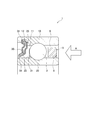
- the inner peripheral surface 34 of the lip portion 33 and the outer peripheral surface 21 of the inner ring 20 are maintained in contact with each other, compared with a case where compressed air does not act.
- the contact area between the inner peripheral surface 34 of the lip portion 33 and the outer peripheral surface 21 of the inner ring 20 may be reduced.
- the lip portion 33 returns to the state shown in FIG.
- the peripheral surface 34 and the outer peripheral surface 21 of the inner ring 20 are in contact with each other, and the contact area between the outer peripheral surface 21 of the inner ring 20 increases. That is, the lip portion 33 is closed. Therefore, the lip portion 33 serves as a brake for the inner ring 20 and the rotating shaft 101 to which the inner ring 20 is fixed, and the rotating shaft 101 can be quickly stopped.
- the shape of the lip portion 33 is an inclined shape that is easily elastically deformed by the action of compressed air, the opening and closing operation of the lip portion 33 by the compressed air can be performed with high sensitivity.
- the outer peripheral surface 21 of the inner ring 20 that is in contact with the inner peripheral surface 34 of the lip portion 33 is a flat surface (substantially annular shape), the outer peripheral surface 21 of the inner ring 20 and the inner peripheral surface of the lip portion 33.
- the contact area of 34 can be increased, and the brake function by the lip portion 33 can be improved.
- the shape of the inner peripheral surface 34 of the lip portion 33 is a substantially annular shape that is similar to the shape of the outer peripheral surface 21 of the inner ring 20. Therefore, since the inner peripheral surface 34 of the lip portion 33 contacts the outer peripheral surface 21 of the inner ring 20 in an area of almost 100% of the entire area, the brake function by the lip portion 33 can be further improved. is there.
- a groove portion 12 for fixing the seal member 30 is formed on the inner peripheral surface 11 of the outer ring 10, and a base portion 31 made of an elastic material at a radially outer end portion of the seal member 30 is attached to the groove portion 12 with a retaining ring 40. Fixed by. Therefore, since the seal member 30 is firmly fixed to the outer ring 10, it is possible to prevent the seal member 30 from dropping off when compressed air is received.
- the fixing method of the seal member 30 to the outer ring 10 is different from the above embodiment.
- the base 31 of the seal member 30 covers the core metal 35 as a whole, and the shape and strength are maintained.
- the lip portion 33 is inclined outward in the axial direction from the cored bar 35 toward the radially inner side.
- the radial direction outer side edge part of the base 31 is crimped to the groove part 12 of the outer ring
- Other configurations and effects are the same as those in the above embodiment.
- the contact area between the inner peripheral surface 34 of the lip portion 33 and the outer peripheral surface 21 of the inner ring 20 is smaller than when compressed air does not act. That is, the inner peripheral surface 34 of the lip portion 33 and the outer peripheral surface 21 of the inner ring 20 may be in a non-contact state (the contact area thereof is zero), and as shown in the example of FIG. A configuration may be employed in which the inner peripheral surface 34 of the portion 33 and the outer peripheral surface 21 of the inner ring 20 are kept in contact with each other, and the contact area is smaller than when compressed air does not act.
- the fixing method of the seal member 30 to the outer ring 10 is different from the above embodiment.
- the base portion 31 of the seal member 30 covers the outside of the cylindrical portion of the core bar 35 having an L-shaped cross section, and the shape and strength are maintained.
- the lip portion 33 is inclined outward in the axial direction from the cored bar 35 toward the radially inner side.
- the radially outer end portion of the base portion 31 is sandwiched and fixed in the axial direction by the axial both surfaces 13 and 14 of the groove portion 12 of the outer ring 10. Even with such a fixing method, since the seal member 30 is firmly fixed to the outer ring 10, it is possible to prevent the seal member 30 from falling off when compressed air is received.
- Other configurations and effects are the same as those in the above embodiment.
- the contact area between the inner peripheral surface 34 of the lip portion 33 and the outer peripheral surface 21 of the inner ring 20 is smaller than when compressed air does not act. That is, the inner peripheral surface 34 of the lip portion 33 and the outer peripheral surface 21 of the inner ring 20 may be in a non-contact state (the contact area is zero), or the inner peripheral surface 34 of the lip portion 33 and A configuration may be employed in which the contact area is smaller than when the compressed air does not act while maintaining a contact state with the outer peripheral surface 21 of the inner ring 20.
- the fixing method of the seal member 30 to the outer ring 10 is different from the above embodiment.
- the sealing member 30 includes a lip portion 33, a base portion 31 made of a metal material that is covered with the lip portion 33 at the radially inner end and extends radially outward from the lip portion 33, Have The lip portion 33 is inclined outward in the axial direction from the base portion 31 toward the radially inner side.
- the base 31 is not covered with the elastic material, and the metal material is exposed (exposed).
- the radial direction outer side edge part of the base 31 is crimped to the groove part 12 of the outer ring
- Even with such a fixing method since the seal member 30 is firmly fixed to the outer ring 10, it is possible to prevent the seal member 30 from falling off when compressed air is received.
- Other configurations and effects are the same as those in the above embodiment.
- the contact area between the inner peripheral surface 34 of the lip portion 33 and the outer peripheral surface 21 of the inner ring 20 is smaller than when compressed air does not act. That is, the inner peripheral surface 34 of the lip portion 33 and the outer peripheral surface 21 of the inner ring 20 may be in a non-contact state (the contact area is zero), or the inner peripheral surface 34 of the lip portion 33 and A configuration may be employed in which the contact area is smaller than when the compressed air does not act while maintaining a contact state with the outer peripheral surface 21 of the inner ring 20.
- the fixing method of the seal member 30 to the outer ring 10 is different from the above embodiment.
- the groove portion 12 of the outer ring 10 includes a tapered surface 15 that inclines radially outward toward the inner side in the axial direction (the ball 3 side), and a radially inner side from the axially inner end of the tapered surface 15. And an axially inner side surface 16 extending in the direction.
- the seal member 30 includes a lip portion 33 and a base portion 31 made of a metal material that is covered with the lip portion 33 at the radially inner end and extends radially outward from the lip portion 33.
- the lip portion 33 is inclined outward in the axial direction from the base portion 31 toward the radially inner side.
- the base 31 is not covered with the elastic material, and the metal material is exposed (exposed).
- the base portion 31 includes a first extending portion 36 extending radially inward from the lip portion 33, a first inclined portion 37 extending inclined from the first extending portion 36 radially inward and axially inward, A second extending portion 38 extending radially inward from the first inclined portion 37 and a second inclined portion 39 extending inclined from the second extending portion 38 inward in the radial direction and outward in the axial direction are provided.
- the contact area between the inner peripheral surface 34 of the lip portion 33 and the outer peripheral surface 21 of the inner ring 20 is smaller than when compressed air does not act. That is, the inner peripheral surface 34 of the lip portion 33 and the outer peripheral surface 21 of the inner ring 20 may be in a non-contact state (the contact area is zero), or the inner peripheral surface 34 of the lip portion 33 and A configuration may be employed in which the contact area is smaller than when the compressed air does not act while maintaining a contact state with the outer peripheral surface 21 of the inner ring 20.
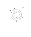
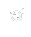
- the shape of the inner peripheral surface 34 of the lip portion 33 is, for example, a substantially elliptical cross section (see FIG. 12) or a substantially triangular cross section ( The modified example shown in FIG. 13 is also within the scope of the present invention.
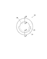
- the inner peripheral surface 34 of the lip portion 33 may be provided with at least one vent hole 41 as shown in FIG. 14, and may be provided with at least one notch 42 as shown in FIGS. 14 shows an example in which one circular ventilation hole 41 is provided, the number of the ventilation holes 41 may be two or more, and the shape of the ventilation hole 41 is not limited to a circle.
- FIGS. 15 to 17 show examples in which two, four, and eight cuts 42 are provided at equal intervals in the circumferential direction, but the number of cuts 42 and the intervals in the circumferential direction are shown here. It is not limited.
- the tip of the lip portion 33 is continuously cut in the circumferential direction, and the inner peripheral surface 34 of the lip portion 33 partially contacts the outer peripheral surface 21 of the inner ring 20.
- the inner peripheral surface 34 of the lip 33 has a contact area (arc length) in contact with the outer peripheral surface 21 of the inner ring 20 that is 50%, 25%, and 10% of the entire inner peripheral surface 34.
- 21A is a cross-sectional view taken along the line AA in FIGS. 18 to 20, and FIG. 21B is taken along the line BB in FIGS. FIG.
- the inner peripheral surface 34 of the lip portion 33 does not completely contact the outer peripheral surface 21 of the inner ring 20, but when the seal member 30 changes from the contact state to the non-contact state, the inner ring 20. Since the frictional force with the outer peripheral surface 21 is generated, there are cases where the state cannot be changed well. Therefore, by providing the air hole 41 or the notch 42 in the inner peripheral surface 34 of the lip portion 33, or by bringing the inner peripheral surface 34 of the lip portion 33 locally into contact with the outer peripheral surface 21 of the inner ring 20, the compressed air is It becomes easy to pass the seal member 30, and the change from the contact state to the non-contact state can be promoted.
- the contact area (the arc length in FIGS. 18 to 20) of the inner peripheral surface 34 of the lip portion 33 shown in FIGS. 12 to 20 is the inner periphery when compressed air does not act. It is desirable that at least 10% or more of the entire surface is in contact with the outer peripheral surface 21 of the inner ring 20. This is to make the seal member 30 easily change from the contact state to the non-contact state when the compressed air hits the seal member 30.
- the contact area is 10% or less of the entire inner peripheral surface, when the compressed air does not act, the contact between the inner peripheral surface 34 of the lip portion 33 and the outer peripheral surface 21 of the inner ring 20 is small, so that the brake function is sufficiently performed. There is no possibility.
- the area may be at least 10% of the entire area of the inner peripheral surface.
- the inner ring 20 may extend outward in the axial direction from the outer ring 10 and the seal member 30 may extend outward in the axial direction from the outer ring 10. I do not care.
- the inner peripheral surface 34 of the lip portion 33 of the seal member 30 is in contact with the outer peripheral surface 21 of the inner ring 20 on the axially outer side than the outer ring 10. According to this configuration, since the inclination of the lip portion 33 can be increased, the opening / closing operation of the lip portion 33 by compressed air can be performed more easily.
- the inclination angle ⁇ of the lip portion 33 of the seal member 30 is preferably set to 35 to 55 °, and the lip portion 33 is preferably brought into contact with the outer peripheral surface 21 of the inner ring 20.
- the lip portion 33 of the seal member 30 is brought into contact with the outer peripheral surface 21 of the inner ring 20, but when the interference between the contact portion of the seal member 30 and the outer peripheral surface 21 of the inner ring 20 is less than 50 ⁇ m. The braking action is weakened and the turbine stop time is lengthened. On the other hand, if the interference exceeds 200 ⁇ m, it becomes difficult for elastic deformation to occur when compressed air acts, and it becomes difficult to reduce the contact area. Therefore, the interference is preferably 50 ⁇ m or more and 200 ⁇ m or less.
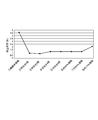
- an evaluation test was performed using a plurality of rolling bearings having different sealing members. Specifically, when the turbine was rotated by the air pressure in each of the following states and the turbine air pressure was stopped, the time for the turbine shaft to completely stop was confirmed. Moreover, in each bearing unit used for the test, a pair of rolling bearings is configured as follows. Furthermore, the test was conducted without changing other turbine specifications and air pressure conditions.
- Test Example 1 A rolling bearing shown in FIG. 24 having a non-contact seal 30a is applied to both rolling bearings.
- Test Example 2 The rolling bearing (FIG. 2) having the seal member 30 having the notched lip portion 33 shown in FIG. 4 is applied to one rolling bearing, and the rolling shown in FIG. 24 is applied to the other rolling bearing. Apply bearings.
- Test Example 3 A rolling bearing (FIG. 2) having a seal member 30 having a lip portion 33 having two notches 42 shown in FIG. 15 is applied to one rolling bearing and FIG. 24 is applied to the other rolling bearing. Apply the rolling bearing shown in.
- Test Example 4 A rolling bearing (FIG. 2) having a seal member 30 having a lip portion 33 having four notches 42 shown in FIG. 16 is applied to one rolling bearing, and FIG.
- Test Example 5 A rolling bearing (FIG. 2) having a seal member 30 having a lip portion 33 having eight notches shown in FIG. 17 is applied to one rolling bearing, and the other rolling bearing is shown in FIG. Apply the rolling bearing shown.
- Test Example 6 A rolling bearing (FIG. 2) having a seal member 30 having a lip portion 33 that is in contact with the outer peripheral surface 21 of the inner ring 20 shown in FIG. 18 is applied to one rolling bearing, and the other rolling bearing is used. In addition, the rolling bearing shown in FIG. 24 is applied.
- Test Example 7 A rolling bearing (FIG. 2) having a seal member 30 having a lip portion 33 that is in contact with the outer peripheral surface 21 of the inner ring 20 shown in FIG.
- Test Example 8 One of the rolling bearings has a configuration similar to that of the sealing member 30 shown in FIG. 20 and has a sealing member 30 having a lip portion 33 that contacts the outer peripheral surface 21 of the inner ring 20 by 15% (FIG. 2). ) And the rolling bearing shown in FIG. 24 is applied to the other rolling bearing.
- the turbine stop time was about 4.5 seconds, but in Test Examples 2 to 8 using the rolling bearing of the present invention on one side, all were stopped. The time was about 2 seconds or less, and the effect of the present invention could be confirmed. In addition, as in Test Examples 3 to 8, even if a notch is provided or the contact area is 15% or more of the inner peripheral surface, the stop time is about 2 seconds or less. The number of rotations can be increased, and can be used properly according to the performance of the turbine.
- the inclination angle ⁇ (see FIG. 23) of the lip portion 33 of the seal member 30 is within a tolerance range of 45 ° ⁇ 10 ° (ie, 35 ° to 55 °). As a result, it was confirmed that when the compressed air acts, the sealing member 30 can be smoothly opened. Further, in Test Examples 2 to 8, the interference is 50 ⁇ m or more and 200 ⁇ m or less, and it has been confirmed that the stop time can be shortened.
Landscapes
- General Engineering & Computer Science (AREA)
- Engineering & Computer Science (AREA)
- Health & Medical Sciences (AREA)
- Mechanical Engineering (AREA)
- Oral & Maxillofacial Surgery (AREA)
- Veterinary Medicine (AREA)
- General Health & Medical Sciences (AREA)
- Public Health (AREA)
- Animal Behavior & Ethology (AREA)
- Life Sciences & Earth Sciences (AREA)
- Epidemiology (AREA)
- Dentistry (AREA)
- Rolling Contact Bearings (AREA)
- Sealing Of Bearings (AREA)
- Mounting Of Bearings Or Others (AREA)
- Dental Tools And Instruments Or Auxiliary Dental Instruments (AREA)
Abstract
Priority Applications (6)
| Application Number | Priority Date | Filing Date | Title |
|---|---|---|---|
| CN201580070706.8A CN107110222B (zh) | 2014-12-25 | 2015-12-24 | 空气涡轮用轴承单元 |
| EP19220102.8A EP3653896B1 (fr) | 2014-12-25 | 2015-12-24 | Palier à roulement pour une unité de palier d'une turbine à air |
| US15/538,806 US10117724B2 (en) | 2014-12-25 | 2015-12-24 | Bearing unit for air turbine |
| JP2016516103A JPWO2016104556A1 (ja) | 2014-12-25 | 2015-12-24 | エアタービン用軸受ユニットおよび歯科エアタービンハンドピース |
| EP15873124.0A EP3239547A4 (fr) | 2014-12-25 | 2015-12-24 | Unité de palier de turbine à air |
| CN201911346639.4A CN111503160B (zh) | 2014-12-25 | 2015-12-24 | 空气涡轮用滚动轴承 |
Applications Claiming Priority (4)
| Application Number | Priority Date | Filing Date | Title |
|---|---|---|---|
| JP2014262876 | 2014-12-25 | ||
| JP2014-262876 | 2014-12-25 | ||
| JP2015-165067 | 2015-08-24 | ||
| JP2015165067 | 2015-08-24 |
Publications (1)
| Publication Number | Publication Date |
|---|---|
| WO2016104556A1 true WO2016104556A1 (fr) | 2016-06-30 |
Family
ID=56150569
Family Applications (1)
| Application Number | Title | Priority Date | Filing Date |
|---|---|---|---|
| PCT/JP2015/085921 Ceased WO2016104556A1 (fr) | 2014-12-25 | 2015-12-24 | Unité de palier de turbine à air |
Country Status (5)
| Country | Link |
|---|---|
| US (1) | US10117724B2 (fr) |
| EP (2) | EP3653896B1 (fr) |
| JP (2) | JPWO2016104556A1 (fr) |
| CN (2) | CN111503160B (fr) |
| WO (1) | WO2016104556A1 (fr) |
Cited By (1)
| Publication number | Priority date | Publication date | Assignee | Title |
|---|---|---|---|---|
| CN106344181A (zh) * | 2016-10-09 | 2017-01-25 | 周展力 | 新型牙科手机机头 |
Families Citing this family (10)
| Publication number | Priority date | Publication date | Assignee | Title |
|---|---|---|---|---|
| US11540902B2 (en) | 2016-03-07 | 2023-01-03 | Nsk Ltd. | Rolling bearing, bearing unit for air turbine, and air turbine handpiece for dental use |
| JP6651912B2 (ja) | 2016-03-07 | 2020-02-19 | 日本精工株式会社 | 転がり軸受及びエアタービン用軸受ユニット |
| EP3609429B1 (fr) | 2017-04-11 | 2023-03-08 | W & H Dentalwerk Bürmoos GmbH | Palier à roulement et pièce à main médicale ou dentaire, fonctionnant avec un gaz sous pression |
| CN107582188B (zh) * | 2017-09-05 | 2023-06-30 | 广东精美医疗科技有限公司 | 一种防气肿牙科手机 |
| DE102018212721A1 (de) * | 2018-07-31 | 2020-02-06 | Minebea Mitsumi Inc. | Wälzlager, insbesondere für ein medizinisches oder kosmetisches Instrument |
| EP3662862B1 (fr) * | 2018-12-05 | 2022-09-28 | Sirona Dental Systems GmbH | Pièce à main dentaire et bouton poussoir pour une pièce à main dentaire |
| JP7367321B2 (ja) * | 2019-03-28 | 2023-10-24 | 日本精工株式会社 | 転がり軸受 |
| US11953057B2 (en) * | 2019-12-27 | 2024-04-09 | Nsk Ltd. | Rolling bearing for air turbine |
| WO2021132688A1 (fr) * | 2019-12-27 | 2021-07-01 | 日本精工株式会社 | Palier à roulement pour turbine à air |
| WO2024260834A1 (fr) | 2023-06-22 | 2024-12-26 | Kavo Dental Gmbh | Pièce à main de turbine médicale |
Citations (4)
| Publication number | Priority date | Publication date | Assignee | Title |
|---|---|---|---|---|
| US4533265A (en) * | 1982-02-09 | 1985-08-06 | Skf (U.K.) Limited | Rolling bearing assemblies fitted with seals |
| JPS62194215U (fr) * | 1986-05-29 | 1987-12-10 | ||
| JPH0866411A (ja) * | 1994-07-01 | 1996-03-12 | Kaltenbach & Voigt Gmbh & Co | 医用または歯科用の処置器具 |
| JP2009002437A (ja) * | 2007-06-21 | 2009-01-08 | Nsk Ltd | 歯科ハンドピース用転がり軸受 |
Family Cites Families (20)
| Publication number | Priority date | Publication date | Assignee | Title |
|---|---|---|---|---|
| US4249896A (en) * | 1978-09-29 | 1981-02-10 | Syntex (U.S.A.) Inc. | Compliantly mountable turbine cartridge assembly for gas-driven dental handpiece |
| FR2671967A1 (fr) * | 1991-01-25 | 1992-07-31 | Bien Air | Piece a main notamment destinee a la chirurgie dentaire, tete de piece a main et appareillage dento-medical equipe d'une telle tete. |
| US5779474A (en) * | 1994-06-09 | 1998-07-14 | Den-Tal-Ez, Inc. | Sudden stop mechanism and air-gap seal for dental handpiece |
| JPH09151948A (ja) | 1995-11-30 | 1997-06-10 | Ntn Corp | シール装置およびこれを用いたロール構造 |
| CZ87696A3 (en) * | 1996-03-25 | 1997-10-15 | Chirana Prema A S | Miniature bearing adapted as a one-way valve, intended particularly for high-speed stomatological drills |
| JP3795722B2 (ja) | 2000-01-27 | 2006-07-12 | 株式会社モリタ製作所 | 医療用切削器械及び医療用切削器械用シール部材 |
| ATE496229T1 (de) * | 2001-08-28 | 2011-02-15 | Kaltenbach & Voigt | Wälzlager, medizinisches oder dentalmedizinisches handstück mit demselben |
| JP3827072B2 (ja) | 2001-11-08 | 2006-09-27 | 株式会社モリタ製作所 | 歯科用又は医療用エアータービンハンドピース |
| JP4160319B2 (ja) * | 2002-05-10 | 2008-10-01 | 株式会社モリタ製作所 | 歯科用切削装置及びサックバック防止方法 |
| DE102005027263A1 (de) * | 2005-04-07 | 2006-10-12 | Kaltenbach & Voigt Gmbh | Medizinisches, insbesondere dentalmedizinisches Handstück |
| JP2009008224A (ja) * | 2007-06-29 | 2009-01-15 | Jtekt Corp | 密封装置 |
| JP2011169399A (ja) * | 2010-02-18 | 2011-09-01 | Nsk Ltd | エンジン補機用転がり軸受 |
| JP5620258B2 (ja) | 2010-12-24 | 2014-11-05 | 株式会社ジェイテクト | 密封装置、及びこれを備えた転がり軸受装置 |
| JP2013152017A (ja) | 2011-12-27 | 2013-08-08 | Nsk Ltd | クリーナモータ用軸受 |
| DE102012000757A1 (de) * | 2012-01-18 | 2013-07-18 | Minebea Co., Ltd. | Wälzlager mit Dichtungssystem |
| JP6065459B2 (ja) * | 2012-05-10 | 2017-01-25 | 日本精工株式会社 | 密封型転がり軸受 |
| FR2994235B1 (fr) * | 2012-08-06 | 2015-01-16 | Skf Ab | Dispositif de roulement, en particulier pour une colonne de direction |
| JP2014126180A (ja) * | 2012-12-27 | 2014-07-07 | Minebea Co Ltd | 流量制御バルブ用玉軸受及びこれを組込んだ排出ガス再循環制御バルブ装置 |
| JP6311273B2 (ja) * | 2013-11-01 | 2018-04-18 | 日本精工株式会社 | アンギュラ玉軸受及び歯科エアタービン |
| JP6291288B2 (ja) | 2014-03-03 | 2018-03-14 | 株式会社熊谷組 | 擁壁の構造 |
-
2015
- 2015-12-24 WO PCT/JP2015/085921 patent/WO2016104556A1/fr not_active Ceased
- 2015-12-24 CN CN201911346639.4A patent/CN111503160B/zh active Active
- 2015-12-24 US US15/538,806 patent/US10117724B2/en active Active
- 2015-12-24 CN CN201580070706.8A patent/CN107110222B/zh active Active
- 2015-12-24 EP EP19220102.8A patent/EP3653896B1/fr active Active
- 2015-12-24 EP EP15873124.0A patent/EP3239547A4/fr not_active Withdrawn
- 2015-12-24 JP JP2016516103A patent/JPWO2016104556A1/ja active Pending
-
2017
- 2017-01-24 JP JP2017010694A patent/JP6350688B2/ja active Active
Patent Citations (4)
| Publication number | Priority date | Publication date | Assignee | Title |
|---|---|---|---|---|
| US4533265A (en) * | 1982-02-09 | 1985-08-06 | Skf (U.K.) Limited | Rolling bearing assemblies fitted with seals |
| JPS62194215U (fr) * | 1986-05-29 | 1987-12-10 | ||
| JPH0866411A (ja) * | 1994-07-01 | 1996-03-12 | Kaltenbach & Voigt Gmbh & Co | 医用または歯科用の処置器具 |
| JP2009002437A (ja) * | 2007-06-21 | 2009-01-08 | Nsk Ltd | 歯科ハンドピース用転がり軸受 |
Non-Patent Citations (1)
| Title |
|---|
| See also references of EP3239547A4 * |
Cited By (1)
| Publication number | Priority date | Publication date | Assignee | Title |
|---|---|---|---|---|
| CN106344181A (zh) * | 2016-10-09 | 2017-01-25 | 周展力 | 新型牙科手机机头 |
Also Published As
| Publication number | Publication date |
|---|---|
| JP2017106630A (ja) | 2017-06-15 |
| EP3239547A1 (fr) | 2017-11-01 |
| US10117724B2 (en) | 2018-11-06 |
| CN111503160B (zh) | 2022-03-15 |
| JP6350688B2 (ja) | 2018-07-04 |
| CN111503160A (zh) | 2020-08-07 |
| CN107110222B (zh) | 2020-01-21 |
| EP3653896B1 (fr) | 2021-10-13 |
| JPWO2016104556A1 (ja) | 2017-04-27 |
| EP3653896A1 (fr) | 2020-05-20 |
| CN107110222A (zh) | 2017-08-29 |
| EP3239547A4 (fr) | 2017-12-20 |
| US20170348069A1 (en) | 2017-12-07 |
Similar Documents
| Publication | Publication Date | Title |
|---|---|---|
| JP6350688B2 (ja) | エアタービン用軸受ユニットおよび歯科エアタービンハンドピース | |
| EP3428468B1 (fr) | Palier de roulement, unité de palier destinée à une turbine à air, et pièce à main de turbine à air à usage dentaire | |
| JP6686738B2 (ja) | 転がり軸受及びエアタービン用軸受ユニット | |
| JP6651912B2 (ja) | 転がり軸受及びエアタービン用軸受ユニット | |
| WO2015188640A1 (fr) | Palier | |
| JP2006336734A (ja) | 密封装置付き転がり軸受 | |
| JP7367321B2 (ja) | 転がり軸受 | |
| JP6311273B2 (ja) | アンギュラ玉軸受及び歯科エアタービン | |
| JP2012127466A (ja) | 転がり軸受の密封装置 | |
| CN114867948B (zh) | 空气涡轮用滚动轴承 | |
| CN114901960B (zh) | 空气涡轮用滚动轴承 | |
| JP2015215061A (ja) | 転がり軸受 | |
| WO2021182637A1 (fr) | Palier à roulement | |
| JP2010276052A (ja) | 玉軸受用保持器および玉軸受 | |
| JP2022157357A5 (fr) | ||
| JP2018009673A (ja) | 転がり軸受 | |
| JP2016166654A (ja) | シール付き転がり軸受 | |
| JP2016089882A (ja) | 転がり軸受 |
Legal Events
| Date | Code | Title | Description |
|---|---|---|---|
| ENP | Entry into the national phase |
Ref document number: 2016516103 Country of ref document: JP Kind code of ref document: A |
|
| 121 | Ep: the epo has been informed by wipo that ep was designated in this application |
Ref document number: 15873124 Country of ref document: EP Kind code of ref document: A1 |
|
| WWE | Wipo information: entry into national phase |
Ref document number: 15538806 Country of ref document: US |
|
| REEP | Request for entry into the european phase |
Ref document number: 2015873124 Country of ref document: EP |
|
| NENP | Non-entry into the national phase |
Ref country code: DE |