WO2016110179A1 - Dispositif de déphasage et antenne à inclinaison électrique - Google Patents
Dispositif de déphasage et antenne à inclinaison électrique Download PDFInfo
- Publication number
- WO2016110179A1 WO2016110179A1 PCT/CN2015/098024 CN2015098024W WO2016110179A1 WO 2016110179 A1 WO2016110179 A1 WO 2016110179A1 CN 2015098024 W CN2015098024 W CN 2015098024W WO 2016110179 A1 WO2016110179 A1 WO 2016110179A1
- Authority
- WO
- WIPO (PCT)
- Prior art keywords
- phase shifting
- shifting device
- substrates
- phase
- substrate
- Prior art date
- Legal status (The legal status is an assumption and is not a legal conclusion. Google has not performed a legal analysis and makes no representation as to the accuracy of the status listed.)
- Ceased
Links
Images



Classifications
-
- H—ELECTRICITY
- H01—ELECTRIC ELEMENTS
- H01Q—ANTENNAS, i.e. RADIO AERIALS
- H01Q3/00—Arrangements for changing or varying the orientation or the shape of the directional pattern of the waves radiated from an antenna or antenna system
- H01Q3/26—Arrangements for changing or varying the orientation or the shape of the directional pattern of the waves radiated from an antenna or antenna system varying the relative phase or relative amplitude of energisation between two or more active radiating elements; varying the distribution of energy across a radiating aperture
- H01Q3/30—Arrangements for changing or varying the orientation or the shape of the directional pattern of the waves radiated from an antenna or antenna system varying the relative phase or relative amplitude of energisation between two or more active radiating elements; varying the distribution of energy across a radiating aperture varying the relative phase between the radiating elements of an array
- H01Q3/32—Arrangements for changing or varying the orientation or the shape of the directional pattern of the waves radiated from an antenna or antenna system varying the relative phase or relative amplitude of energisation between two or more active radiating elements; varying the distribution of energy across a radiating aperture varying the relative phase between the radiating elements of an array by mechanical means
-
- H—ELECTRICITY
- H01—ELECTRIC ELEMENTS
- H01P—WAVEGUIDES; RESONATORS, LINES, OR OTHER DEVICES OF THE WAVEGUIDE TYPE
- H01P1/00—Auxiliary devices
- H01P1/18—Phase-shifters
-
- H—ELECTRICITY
- H01—ELECTRIC ELEMENTS
- H01P—WAVEGUIDES; RESONATORS, LINES, OR OTHER DEVICES OF THE WAVEGUIDE TYPE
- H01P1/00—Auxiliary devices
- H01P1/18—Phase-shifters
- H01P1/184—Strip line phase-shifters
-
- H—ELECTRICITY
- H01—ELECTRIC ELEMENTS
- H01Q—ANTENNAS, i.e. RADIO AERIALS
- H01Q1/00—Details of, or arrangements associated with, antennas
- H01Q1/48—Earthing means; Earth screens; Counterpoises
Definitions
- the present invention relates generally to the field of wireless communications and, more particularly, to a phase shifting apparatus for an electronically modulated antenna.
- Phase Shifter network is an important part of the ESC antenna.
- the phase shifter is mainly used in the electric adjustment antenna to adjust the phase change of the feed network, thereby changing the phase of each or a group of radiation units to achieve the purpose of changing the vertical beam angle or the horizontal beam angle.
- an air strip line is often used to transmit signals, and a phase change is achieved by placing a movable medium below a specific position of the strip line.
- Stripline tends to have the following disadvantages: First, the stripline is long and thin, so it is easily deformed, and sometimes welding is required between the two striplines; secondly, a part of the PSN is fixed by screws, and Metal screws can affect the performance of PSN passive intermodulation (PIM); in addition, the current phase shifting unit structure that constitutes PSN is complex, difficult to assemble and rework, and PSN can sometimes include more phase shifting units. When the PSN is used for environmental testing, the Antenna Control Unit (ACU) cannot drive the phase shifting device, which causes inconvenience to the use of the PSN and limits the use of the PSN.
- ACU Antenna Control Unit
- phase shifting device that has good PIM performance and is easy to assemble.
- the present invention proposes a phase shifting device having good PIM performance and being easy to assemble, and an electric adjustable antenna using the phase shifting device.
- phase shifting device including: a ground plate; at least two bottom substrates respectively located on both sides of the ground plate and coupled to the ground plate; at least two top substrates, They are respectively located on both sides of the two bottom substrates, each of which is a top substrate and each of the bottom substrates form a phase shifting unit; a tie rod coupled to the two top substrates for adjusting a relative relationship between the at least two top substrates and the two bottom substrates Sliding to simultaneously adjust the phase of each of the phase shifting unit output signals.
- the above embodiment realizes a phase shifting device having at least two phase shifting units, and can simultaneously adjust two phase shifting units for phase shifting with opposite phase change trends, achieving a larger sliding stroke with a smaller sliding stroke.
- the phase difference reduces the volume of the phase shifting device.
- At least one signal input line and at least one phase shift signal output line of the bottom substrate facing the top substrate are disposed.
- At least one U-shaped line is disposed on a side of the top substrate facing the bottom substrate, the at least one U-shaped line being coupled to the at least one signal input line and the at least one phase shifting signal Output line.
- each phase shifting unit will include at least one phase shifter, and each phase shifter has a one-to-one correspondence with the U-shaped line.
- the phase shifting device further includes: a fixing member for fixing the two top substrates to each other, and the tie rod is coupled to the two top substrates by the fixing member.
- the fixing component comprises: two first fasteners and a second firmware that can be fastened to each other, and the top substrate is adhered to the bottom substrate when the first and second fasteners are fastened.
- the first firmware is provided with at least one rivet and at least one groove
- the second firmware is correspondingly provided with at least one rivet and at least one groove, so that the first firmware and the second firmware
- the rivets and grooves can be matched to form a fixed connection.
- phase shifting device does not require the use of screws when assembled, providing the possibility of using a variety of materials.
- the top substrate is provided with at least two through holes for the rivets on the first and second firmware to pass through; and the bottom substrate is provided with at least one long hole for providing the The movement space of the rivet on the first and second firmware.
- the phase shifting device further comprises: a plate rivet for connecting the two bottom substrates with the through holes provided on the two bottom substrates and the through holes provided on the ground plate The floor is fixed.
- the bottom substrate and the top substrate are covered with an insulating layer at other positions except for soldering.
- a side of the bottom substrate facing the top substrate is provided with a signal input line and three phase shifting signal output lines, wherein two of the three phase shifting signal output lines are connected by an external conductor.
- the fixing member and/or the plate rivet are made of a non-metallic material.
- the phase shifting device does not employ or relatively less use of metal components, thereby improving the PIM performance of the phase shifting device.
- an electrical adjustment antenna including: a phase shifting device; an antenna control unit coupled to the pull rod for driving the pull rod, thereby enabling the two top substrates to be simultaneously Sliding relative to the two bottom substrates.
- the phase shifting device does not need to use screws when assembling, and the metal component is avoided or relatively less, thereby improving the PIM performance of the phase shifting device.
- the top substrate is moved, its friction is small, enabling the ACU to drive the drawbar at low temperatures, and the phase shifting device has few parts and low cost, and is connected by non-metallic rivets, which is easy to assemble and rework.
- FIG. 1 is an exploded view of a phase shifting device in accordance with an embodiment of the present invention
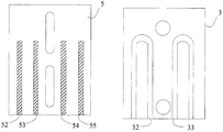
- FIG. 2 is a schematic diagram of a base substrate and a top substrate according to an embodiment of the invention.
- FIG. 3 is a schematic diagram of a phase shifting signal of an antenna according to an embodiment of the present invention.
- 4a is a schematic view of a phase shifting device before being assembled and slid according to an embodiment of the present invention
- 4b is a schematic view of the phase shifting device after being assembled and slid according to an embodiment of the present invention
- 5a is a simulation diagram of passive intermodulation of a phase shifting device at a carrier frequency of 1900 MHz according to an embodiment of the present invention
- FIG. 5b is a simulation diagram of passive intermodulation of a phase shifting device at a carrier frequency of 2600 MHz according to an embodiment of the invention.
- FIG. 1 is an exploded view of a phase shifting device in accordance with an embodiment of the present invention.
- the phase shifting device includes: a tie rod 1 , two fixing members 2 , two top substrates 3 , two bottom substrates 5 , and a ground plate 6 , wherein the top substrate 3 and the bottom substrate 5 constitute a phase shifting unit. That is to say, the phase shifting device comprises two phase shifting units distributed on the lower two sides of the grounding plate, and each phase shifting unit may comprise at least one phase shifter.
- the two bottom substrates 5 are respectively located at two sides of the grounding plate 6, and are electrically coupled to the grounding plate 6.
- the two bottom substrates 5 further include a signal input line and a phase shifting signal output line (not shown);
- Two top substrates 3 are respectively disposed on two sides of the two bottom substrates 5, that is, the top substrate 3, the bottom substrate 5 and the ground plate 6 are sequentially disposed;
- the tie rod 1 is used for adjusting the relative sliding between the top substrate and the two bottom substrates, thereby The phase of each phase shifting unit output signal can be adjusted simultaneously and with opposite phase changes.
- FIG. 2 is a schematic diagram of a base substrate and a top substrate in accordance with an embodiment of the present invention.
- the bottom substrate 5 faces at the side of the top substrate 3 with at least one signal input line and at least one phase shift signal output line, for example, one signal input line 52 and three phase shift signal output lines 53-55, respectively.
- the side of the top substrate facing the bottom substrate is provided with at least one U-shaped wire, such as two U-shaped wires 32, 33, when the bottom substrate and the top substrate are close or even When laminated, even if the surface is covered with an insulating layer, signals between the two substrates can be transmitted by coupling. Therefore, the two U-shaped lines in the figure implement two phase shifters, that is, the phase shifting unit contains two phase shifters.
- Figure 2 does not show all the details of the base substrate and the top substrate, only the portions associated with signal coupling are shown.
- the bottom substrate 5 and the top substrate 3 are covered with an insulating layer, such as a liquid photo solder resist (green oil), except for soldering.
- an insulating layer such as a liquid photo solder resist (green oil), except for soldering.
- the fixing member 2 is for fixing the two top substrates 3 located on both sides of the ground plate 6 to each other.
- the fixing member 2 is also coupled to the pull rod 1 so that when the pull rod 1 is moved left and right, it will drive the top substrate 3 distributed on both sides of the ground plate 6 to move in the same direction.
- the fixing component 2 comprises two first firmware and a second firmware that can be fastened to each other.
- the first firmware is provided with at least one rivet 21 and at least one groove
- the second firmware is correspondingly provided with at least one rivet 21 and at least one groove, so that the rivet can be passed between the first firmware and the second firmware.
- at least two through holes 31 are provided in the top substrate 3 for the rivets 21 on the first and second firmware to pass through to be fixed.
- At least one long hole such as two long holes 51, is provided on the bottom substrate for providing a movement space of the rivet 21 on the first and second firmware. That is, the rivets 21 on the first firmware will sequentially pass through the through holes 31, the long holes 51 and the long holes 61 and then pass through the long holes 51, the through holes 31 on the other side, and finally the concave on the second firmware.
- the slots are inserted to form a fixed connection.
- the phase shifting device further includes a plate rivet 7.
- the board rivet 7 fixes the two base substrates and the ground plate to each other through a through hole 56 provided in the two bottom substrates 5 and a through hole 62 provided in the ground plate.
- FIG. 3 is a schematic diagram of a phase shifting signal of an antenna according to an embodiment of the invention.
- C0 is the input cable
- C1, C2 are the cables between the power splitter and the phase shifter
- C3-C4, C6-C7 are the cables from the phase shifter to the power splitter
- C5 is the two power distributions.
- the cable between the devices, C8-C17, is the desired phase shift signal.
- the phase shifting device in this embodiment is a portion in the dotted line frame. Therefore, the aforementioned signal input line 52 disposed on the two bottom substrates corresponds to C1 and C2, and similarly, the phase shifting on the two bottom substrates is provided. Output lines 53-55 correspond to C3-C4 and C6-C7.
- the cables 8-11 are respectively coupled to the base substrate 5 through the coupling block 4.
- a signal input line 52 and three phase shift signal output lines 53-55 are provided.
- the cables 8, 12-14 are respectively coupled to the signal input line and the three phase shift signal output lines on the other bottom substrate 5.
- the cables 9, 10 are connected, and the cables 12, 13 are connected to form corresponding C4 and C6, respectively.
- the pull rod 1 drives the upper and lower top substrates to move in the same direction, it is obvious that the transmission path between the upper and lower two substrates and the two bottom substrates changes, that is, one becomes larger and smaller, so that C3 and The phase difference between C7 becomes large. Therefore, in this embodiment, the arrangement of the upper and lower substrates is such that the top substrate only needs to be moved by a small distance, so that the effect of changing the phase difference can be achieved. Therefore, the phase shifting device can be made. Relatively small to save costs.
- the fixing member 2 and/or the plate rivet 7 described above are made of a non-metallic material, which can improve the PIM performance of the phase shifting device.
- the non-metallic materials herein may be plastics, rubber, and the like.
- FIG. 4a is a schematic view showing a state before the phase shifting device is assembled and slid according to an embodiment of the present invention
- FIG. 4b is a schematic view showing a state after the phase shifting device is assembled and slid according to an embodiment of the present invention.
- the length of the signal transmission path can be significantly changed, so that a large phase difference can be realized on both the left and right sides of the phase shifting device by sliding only a small distance.
- the invention also proposes an electrical adjustment antenna, comprising: the antenna comprises the phase shifting device described above And the ACU, wherein the ACU is coupled to the pull rod 1 for driving the pull rod 1, thereby enabling the two top substrates to slide simultaneously with respect to the two bottom substrates, so that a large phase difference can be realized with a small sliding stroke.
- FIG. 5a is a simulation diagram of passive intermodulation of a phase shifting device at a carrier frequency of 1900 MHz according to an embodiment of the invention
- FIG. 5b is a simulation diagram of passive intermodulation of a phase shifting device at a carrier frequency of 2600 MHz according to an embodiment of the invention.
- the relative value expression can better reflect the stability of the passive intermodulation of the phase shifting device, that is, the ratio of the passive intermodulation value to the carrier frequency. For dBc.
- Fig. 5a Under the condition of 20W transmission power, it can be observed from Fig. 5a that the worst case of passive intermodulation is 173dBc at 1900MHz carrier frequency; as shown in Fig. 5b, at 2600MHz carrier frequency, The worst case of passive intermodulation of the phase shifting device is -172dBc.
- phase shifting device of the present invention has stable PIM performance.
- the phase shifting device of the present invention comprises two phase shifting units, and can simultaneously adjust two phase shifting units for phase shifting with opposite phase change trends, thereby realizing a larger sliding stroke.
- the phase difference reduces the volume of the phase shifting device.
- the phase shifting device does not require the use of screws during assembly, which avoids the use of metal components to affect the PIM performance of the phase shifting device, and the friction of the top substrate is small, allowing the ACU to drive the drawbar at low temperatures.
- the phase shifting device described above has few parts, is relatively low cost, and is connected using non-metallic rivets, which is very easy to assemble and rework.
Landscapes
- Waveguide Switches, Polarizers, And Phase Shifters (AREA)
Abstract
La présente invention concerne un dispositif de déphasage et une antenne à inclinaison électrique. Le dispositif de déphasage comprend : une plaque de masse ; deux substrats inférieurs disposés respectivement des deux côtés de la plaque de masse et couplés à la plaque de masse ; deux substrats supérieurs disposés respectivement des deux côtés des deux substrats inférieurs, chaque substrat supérieur et chaque substrat inférieur formant une unité de déphasage ; une barre de traction accouplée aux deux substrats supérieurs et utilisée pour ajuster le coulissement relatif entre les deux substrats supérieurs et les deux substrats inférieurs de manière à régler la phase du signal de sortie de chaque unité de déphasage en même temps. Au moyen de la solution technique de la présente invention, des vis ne sont pas nécessaires au cours de l'assemblage du dispositif de déphasage, les performances PIM du dispositif de déphasage sont améliorées, et les frottements sont moindres, de manière qu'une ACU peut entraîner la barre de traction à une basse température. Le dispositif de déphasage, qui présente peu de pièces, un faible coût et des liaisons par utilisation de rivets non métalliques, est très facile à assembler et à réusiner.
Priority Applications (2)
| Application Number | Priority Date | Filing Date | Title |
|---|---|---|---|
| EP15876679.0A EP3244479B1 (fr) | 2015-01-05 | 2015-12-21 | Dispositif de déphasage et antenne avec inclinaison électrique |
| US15/541,539 US10411346B2 (en) | 2015-01-05 | 2015-12-21 | Phase shifting apparatus and electrically adjustable antenna |
Applications Claiming Priority (2)
| Application Number | Priority Date | Filing Date | Title |
|---|---|---|---|
| CN201510003349.5A CN105826684B (zh) | 2015-01-05 | 2015-01-05 | 移相装置和电调天线 |
| CN201510003349.5 | 2015-01-05 |
Publications (1)
| Publication Number | Publication Date |
|---|---|
| WO2016110179A1 true WO2016110179A1 (fr) | 2016-07-14 |
Family
ID=56355498
Family Applications (1)
| Application Number | Title | Priority Date | Filing Date |
|---|---|---|---|
| PCT/CN2015/098024 Ceased WO2016110179A1 (fr) | 2015-01-05 | 2015-12-21 | Dispositif de déphasage et antenne à inclinaison électrique |
Country Status (4)
| Country | Link |
|---|---|
| US (1) | US10411346B2 (fr) |
| EP (1) | EP3244479B1 (fr) |
| CN (1) | CN105826684B (fr) |
| WO (1) | WO2016110179A1 (fr) |
Cited By (1)
| Publication number | Priority date | Publication date | Assignee | Title |
|---|---|---|---|---|
| CN109768391A (zh) * | 2018-12-29 | 2019-05-17 | 京信通信技术(广州)有限公司 | 天线、天线电下倾角的显示系统及其传动机构 |
Families Citing this family (8)
| Publication number | Priority date | Publication date | Assignee | Title |
|---|---|---|---|---|
| CN108260276A (zh) * | 2016-12-29 | 2018-07-06 | 安弗施无线射频系统(上海)有限公司 | 一种印刷电路板的驻波比调制结构和方法 |
| US11502407B2 (en) | 2018-07-12 | 2022-11-15 | Commscope Technologies Llc | Remote electronic tilt base station antennas having adjustable ret linkages |
| CN109802234B (zh) * | 2019-01-30 | 2023-09-29 | 京信通信技术(广州)有限公司 | 基站天线及移相馈电装置 |
| WO2021056554A1 (fr) * | 2019-09-29 | 2021-04-01 | 华为技术有限公司 | Appareil de réglage, antenne multibande, et station de base |
| CN114447561A (zh) * | 2020-11-05 | 2022-05-06 | 康普技术有限责任公司 | 用于基站天线的移相器的支撑装置 |
| US11942682B2 (en) | 2021-04-21 | 2024-03-26 | Skyworks Solutions, Inc. | Electrically adjustable stencil for controlling antenna pattern for beamforming |
| KR200497886Y1 (ko) * | 2021-11-11 | 2024-03-25 | 주식회사 에이스테크놀로지 | 뒤틀림 방지를 위한 밀리미터 웨이브용 페이즈 쉬프터 구동 장치 |
| CN114188681B (zh) * | 2022-01-13 | 2025-04-18 | 江苏三晟信息科技有限公司 | 一种新型的小型化u形耦合线微带移相器 |
Citations (5)
| Publication number | Priority date | Publication date | Assignee | Title |
|---|---|---|---|---|
| EP0984509B1 (fr) * | 1998-09-04 | 2004-05-19 | Agere Systems Optoelectronics Guardian Corporation | Déphaseur en mode réflection |
| CN102544733A (zh) * | 2012-01-31 | 2012-07-04 | 广东博纬通信科技有限公司 | 一种基站电调天线相位连续线性可变的移相器 |
| CN202423518U (zh) * | 2011-12-30 | 2012-09-05 | 东莞市晖速天线技术有限公司 | 提高移相量和集成度的移相器及具有该移相器的基站天线 |
| CN104051823A (zh) * | 2014-06-06 | 2014-09-17 | 摩比天线技术(深圳)有限公司 | 移相器 |
| CN204424453U (zh) * | 2015-01-05 | 2015-06-24 | 安弗施无线射频系统(上海)有限公司 | 移相装置和电调天线 |
Family Cites Families (15)
| Publication number | Priority date | Publication date | Assignee | Title |
|---|---|---|---|---|
| US7274331B2 (en) * | 2001-12-03 | 2007-09-25 | Huber + Suhner Ag | Phase-shifting system using a displaceable dielectric and phase array antenna comprising such a phase-shifting system |
| GB0215087D0 (en) * | 2002-06-29 | 2002-08-07 | Alan Dick & Company Ltd | A phase shifting device |
| US20050219133A1 (en) * | 2004-04-06 | 2005-10-06 | Elliot Robert D | Phase shifting network |
| GB2426635A (en) * | 2005-05-27 | 2006-11-29 | Alan Dick & Company Ltd | Phase shifting arrangement |
| JP4341699B2 (ja) * | 2007-05-31 | 2009-10-07 | 日立電線株式会社 | 移相器 |
| JP4780097B2 (ja) | 2007-12-11 | 2011-09-28 | 日立電線株式会社 | 移相器 |
| CN201174411Y (zh) * | 2008-04-01 | 2008-12-31 | 京信通信系统(中国)有限公司 | 复合移相器 |
| CN101707271B (zh) * | 2008-12-24 | 2012-01-25 | 广东通宇通讯股份有限公司 | 等相差分多路复合移相器 |
| CN201838690U (zh) * | 2010-08-03 | 2011-05-18 | 东莞台霖电子通讯有限公司 | 具有反向相对配置型态电调单元的移相器 |
| CN102263313A (zh) * | 2011-07-27 | 2011-11-30 | 华为技术有限公司 | 一种移相装置及其应用的天线系统 |
| CN202839907U (zh) * | 2012-10-22 | 2013-03-27 | 华为技术有限公司 | 移相器和具有移相器的天线 |
| CN103050764A (zh) | 2012-12-17 | 2013-04-17 | 广东博纬通信科技有限公司 | 等相差分波束形成装置 |
| CN103117425A (zh) * | 2013-02-07 | 2013-05-22 | 武汉虹信通信技术有限责任公司 | 一种连续可调移相装置 |
| CN104103875B (zh) * | 2014-07-22 | 2017-10-13 | 京信通信系统(中国)有限公司 | 移相器及包含移相器的移相组件、移相馈电网络 |
| CN104201440A (zh) | 2014-08-21 | 2014-12-10 | 摩比天线技术(深圳)有限公司 | 基站电调天线的介质移相器 |
-
2015
- 2015-01-05 CN CN201510003349.5A patent/CN105826684B/zh not_active Expired - Fee Related
- 2015-12-21 WO PCT/CN2015/098024 patent/WO2016110179A1/fr not_active Ceased
- 2015-12-21 EP EP15876679.0A patent/EP3244479B1/fr not_active Not-in-force
- 2015-12-21 US US15/541,539 patent/US10411346B2/en active Active
Patent Citations (5)
| Publication number | Priority date | Publication date | Assignee | Title |
|---|---|---|---|---|
| EP0984509B1 (fr) * | 1998-09-04 | 2004-05-19 | Agere Systems Optoelectronics Guardian Corporation | Déphaseur en mode réflection |
| CN202423518U (zh) * | 2011-12-30 | 2012-09-05 | 东莞市晖速天线技术有限公司 | 提高移相量和集成度的移相器及具有该移相器的基站天线 |
| CN102544733A (zh) * | 2012-01-31 | 2012-07-04 | 广东博纬通信科技有限公司 | 一种基站电调天线相位连续线性可变的移相器 |
| CN104051823A (zh) * | 2014-06-06 | 2014-09-17 | 摩比天线技术(深圳)有限公司 | 移相器 |
| CN204424453U (zh) * | 2015-01-05 | 2015-06-24 | 安弗施无线射频系统(上海)有限公司 | 移相装置和电调天线 |
Cited By (1)
| Publication number | Priority date | Publication date | Assignee | Title |
|---|---|---|---|---|
| CN109768391A (zh) * | 2018-12-29 | 2019-05-17 | 京信通信技术(广州)有限公司 | 天线、天线电下倾角的显示系统及其传动机构 |
Also Published As
| Publication number | Publication date |
|---|---|
| US10411346B2 (en) | 2019-09-10 |
| CN105826684B (zh) | 2019-07-02 |
| CN105826684A (zh) | 2016-08-03 |
| EP3244479B1 (fr) | 2021-12-22 |
| EP3244479A1 (fr) | 2017-11-15 |
| EP3244479A4 (fr) | 2018-08-22 |
| US20180026366A1 (en) | 2018-01-25 |
Similar Documents
| Publication | Publication Date | Title |
|---|---|---|
| WO2016110179A1 (fr) | Dispositif de déphasage et antenne à inclinaison électrique | |
| US11870157B2 (en) | Phase shifter and remote electrical tilt antenna | |
| KR102466972B1 (ko) | 스위칭 가능한 송수신 페이즈드 어레이 안테나 | |
| JP5417433B2 (ja) | デュアルビーム二重選択偏波アンテナ | |
| US10693227B2 (en) | Patch array antenna, directivity control method therefor and wireless device using patch array antenna | |
| CN109904597B (zh) | 一种馈电设备、天线及电子设备 | |
| CN204424453U (zh) | 移相装置和电调天线 | |
| WO2021103748A1 (fr) | Déphaseur diélectrique | |
| CN109244679A (zh) | 一种紧凑型多波束天线阵列系统 | |
| WO2016074593A1 (fr) | Écran acoustique pour antenne de station de base et structure de réseau d'antennes de station de base | |
| CN110676566A (zh) | 天线系统 | |
| KR20060064606A (ko) | 양면 에지-장착 스트립라인 신호 처리 모듈 및 모듈러네트워크 | |
| WO2016037549A1 (fr) | Déphaseur | |
| JP2020521400A (ja) | 単層pcbにおける広帯域導波管発射設計 | |
| JP5712639B2 (ja) | ダイポールアンテナおよびアレーアンテナ | |
| JP2020501460A (ja) | 低損失電送機構及びそれを使用するアンテナ | |
| CN208674382U (zh) | 一种紧凑型多波束天线阵列系统 | |
| CN109273842A (zh) | 背靠背多层堆叠结构的mems移相器的相控阵天线单元 | |
| US11557820B2 (en) | Phase shifter having a substrate with a signal feed line thereon and including a replaceable dielectric board fixed to the substrate and covering the feed line | |
| JP6867322B2 (ja) | 回路および無線装置 | |
| US20180083335A1 (en) | Cable and high-frequency device using same | |
| JP6565838B2 (ja) | 導波管型可変移相器および導波管スロットアレーアンテナ装置 | |
| CN209767534U (zh) | T型偏置电路以及用于基站天线的校准板 | |
| JP2017188749A (ja) | 移相器及びこれを備えたアンテナ装置 | |
| CN104505560B (zh) | 相位调节装置及相位调节单元 |
Legal Events
| Date | Code | Title | Description |
|---|---|---|---|
| 121 | Ep: the epo has been informed by wipo that ep was designated in this application |
Ref document number: 15876679 Country of ref document: EP Kind code of ref document: A1 |
|
| REEP | Request for entry into the european phase |
Ref document number: 2015876679 Country of ref document: EP |
|
| WWE | Wipo information: entry into national phase |
Ref document number: 15541539 Country of ref document: US |
|
| NENP | Non-entry into the national phase |
Ref country code: DE |