WO2016110733A1 - Dispositif de génération d'itinéraire cible, et dispositif de commande d'entraînement - Google Patents
Dispositif de génération d'itinéraire cible, et dispositif de commande d'entraînement Download PDFInfo
- Publication number
- WO2016110733A1 WO2016110733A1 PCT/IB2015/001087 IB2015001087W WO2016110733A1 WO 2016110733 A1 WO2016110733 A1 WO 2016110733A1 IB 2015001087 W IB2015001087 W IB 2015001087W WO 2016110733 A1 WO2016110733 A1 WO 2016110733A1
- Authority
- WO
- WIPO (PCT)
- Prior art keywords
- section
- target
- vehicle speed
- vehicle
- route
- Prior art date
- Legal status (The legal status is an assumption and is not a legal conclusion. Google has not performed a legal analysis and makes no representation as to the accuracy of the status listed.)
- Ceased
Links
Images

Classifications
-
- G—PHYSICS
- G01—MEASURING; TESTING
- G01C—MEASURING DISTANCES, LEVELS OR BEARINGS; SURVEYING; NAVIGATION; GYROSCOPIC INSTRUMENTS; PHOTOGRAMMETRY OR VIDEOGRAMMETRY
- G01C21/00—Navigation; Navigational instruments not provided for in groups G01C1/00 - G01C19/00
- G01C21/26—Navigation; Navigational instruments not provided for in groups G01C1/00 - G01C19/00 specially adapted for navigation in a road network
- G01C21/34—Route searching; Route guidance
- G01C21/3407—Route searching; Route guidance specially adapted for specific applications
-
- B—PERFORMING OPERATIONS; TRANSPORTING
- B60—VEHICLES IN GENERAL
- B60K—ARRANGEMENT OR MOUNTING OF PROPULSION UNITS OR OF TRANSMISSIONS IN VEHICLES; ARRANGEMENT OR MOUNTING OF PLURAL DIVERSE PRIME-MOVERS IN VEHICLES; AUXILIARY DRIVES FOR VEHICLES; INSTRUMENTATION OR DASHBOARDS FOR VEHICLES; ARRANGEMENTS IN CONNECTION WITH COOLING, AIR INTAKE, GAS EXHAUST OR FUEL SUPPLY OF PROPULSION UNITS IN VEHICLES
- B60K31/00—Vehicle fittings, acting on a single sub-unit only, for automatically controlling vehicle speed, i.e. preventing speed from exceeding an arbitrarily established velocity or maintaining speed at a particular velocity, as selected by the vehicle operator
-
- B—PERFORMING OPERATIONS; TRANSPORTING
- B60—VEHICLES IN GENERAL
- B60W—CONJOINT CONTROL OF VEHICLE SUB-UNITS OF DIFFERENT TYPE OR DIFFERENT FUNCTION; CONTROL SYSTEMS SPECIALLY ADAPTED FOR HYBRID VEHICLES; ROAD VEHICLE DRIVE CONTROL SYSTEMS FOR PURPOSES NOT RELATED TO THE CONTROL OF A PARTICULAR SUB-UNIT
- B60W40/00—Estimation or calculation of non-directly measurable driving parameters for road vehicle drive control systems not related to the control of a particular sub unit, e.g. by using mathematical models
- B60W40/10—Estimation or calculation of non-directly measurable driving parameters for road vehicle drive control systems not related to the control of a particular sub unit, e.g. by using mathematical models related to vehicle motion
- B60W40/105—Speed
-
- B—PERFORMING OPERATIONS; TRANSPORTING
- B60—VEHICLES IN GENERAL
- B60W—CONJOINT CONTROL OF VEHICLE SUB-UNITS OF DIFFERENT TYPE OR DIFFERENT FUNCTION; CONTROL SYSTEMS SPECIALLY ADAPTED FOR HYBRID VEHICLES; ROAD VEHICLE DRIVE CONTROL SYSTEMS FOR PURPOSES NOT RELATED TO THE CONTROL OF A PARTICULAR SUB-UNIT
- B60W60/00—Drive control systems specially adapted for autonomous road vehicles
- B60W60/001—Planning or execution of driving tasks
-
- G—PHYSICS
- G01—MEASURING; TESTING
- G01C—MEASURING DISTANCES, LEVELS OR BEARINGS; SURVEYING; NAVIGATION; GYROSCOPIC INSTRUMENTS; PHOTOGRAMMETRY OR VIDEOGRAMMETRY
- G01C21/00—Navigation; Navigational instruments not provided for in groups G01C1/00 - G01C19/00
- G01C21/26—Navigation; Navigational instruments not provided for in groups G01C1/00 - G01C19/00 specially adapted for navigation in a road network
- G01C21/34—Route searching; Route guidance
-
- G—PHYSICS
- G05—CONTROLLING; REGULATING
- G05D—SYSTEMS FOR CONTROLLING OR REGULATING NON-ELECTRIC VARIABLES
- G05D1/00—Control of position, course, altitude or attitude of land, water, air or space vehicles, e.g. using automatic pilots
- G05D1/02—Control of position or course in two dimensions
- G05D1/021—Control of position or course in two dimensions specially adapted to land vehicles
- G05D1/0231—Control of position or course in two dimensions specially adapted to land vehicles using optical position detecting means
- G05D1/0246—Control of position or course in two dimensions specially adapted to land vehicles using optical position detecting means using a video camera in combination with image processing means
-
- G—PHYSICS
- G05—CONTROLLING; REGULATING
- G05D—SYSTEMS FOR CONTROLLING OR REGULATING NON-ELECTRIC VARIABLES
- G05D1/00—Control of position, course, altitude or attitude of land, water, air or space vehicles, e.g. using automatic pilots
- G05D1/02—Control of position or course in two dimensions
- G05D1/021—Control of position or course in two dimensions specially adapted to land vehicles
- G05D1/0257—Control of position or course in two dimensions specially adapted to land vehicles using a radar
-
- G—PHYSICS
- G08—SIGNALLING
- G08G—TRAFFIC CONTROL SYSTEMS
- G08G1/00—Traffic control systems for road vehicles
- G08G1/09—Arrangements for giving variable traffic instructions
-
- G—PHYSICS
- G08—SIGNALLING
- G08G—TRAFFIC CONTROL SYSTEMS
- G08G1/00—Traffic control systems for road vehicles
- G08G1/09—Arrangements for giving variable traffic instructions
- G08G1/0962—Arrangements for giving variable traffic instructions having an indicator mounted inside the vehicle, e.g. giving voice messages
- G08G1/0967—Systems involving transmission of highway information, e.g. weather, speed limits
- G08G1/096708—Systems involving transmission of highway information, e.g. weather, speed limits where the received information might be used to generate an automatic action on the vehicle control
- G08G1/096725—Systems involving transmission of highway information, e.g. weather, speed limits where the received information might be used to generate an automatic action on the vehicle control where the received information generates an automatic action on the vehicle control
-
- G—PHYSICS
- G08—SIGNALLING
- G08G—TRAFFIC CONTROL SYSTEMS
- G08G1/00—Traffic control systems for road vehicles
- G08G1/09—Arrangements for giving variable traffic instructions
- G08G1/0962—Arrangements for giving variable traffic instructions having an indicator mounted inside the vehicle, e.g. giving voice messages
- G08G1/0968—Systems involving transmission of navigation instructions to the vehicle
-
- B—PERFORMING OPERATIONS; TRANSPORTING
- B60—VEHICLES IN GENERAL
- B60W—CONJOINT CONTROL OF VEHICLE SUB-UNITS OF DIFFERENT TYPE OR DIFFERENT FUNCTION; CONTROL SYSTEMS SPECIALLY ADAPTED FOR HYBRID VEHICLES; ROAD VEHICLE DRIVE CONTROL SYSTEMS FOR PURPOSES NOT RELATED TO THE CONTROL OF A PARTICULAR SUB-UNIT
- B60W2420/00—Indexing codes relating to the type of sensors based on the principle of their operation
- B60W2420/40—Photo, light or radio wave sensitive means, e.g. infrared sensors
- B60W2420/403—Image sensing, e.g. optical camera
-
- B—PERFORMING OPERATIONS; TRANSPORTING
- B60—VEHICLES IN GENERAL
- B60W—CONJOINT CONTROL OF VEHICLE SUB-UNITS OF DIFFERENT TYPE OR DIFFERENT FUNCTION; CONTROL SYSTEMS SPECIALLY ADAPTED FOR HYBRID VEHICLES; ROAD VEHICLE DRIVE CONTROL SYSTEMS FOR PURPOSES NOT RELATED TO THE CONTROL OF A PARTICULAR SUB-UNIT
- B60W2420/00—Indexing codes relating to the type of sensors based on the principle of their operation
- B60W2420/40—Photo, light or radio wave sensitive means, e.g. infrared sensors
- B60W2420/408—Radar; Laser, e.g. lidar
-
- B—PERFORMING OPERATIONS; TRANSPORTING
- B60—VEHICLES IN GENERAL
- B60W—CONJOINT CONTROL OF VEHICLE SUB-UNITS OF DIFFERENT TYPE OR DIFFERENT FUNCTION; CONTROL SYSTEMS SPECIALLY ADAPTED FOR HYBRID VEHICLES; ROAD VEHICLE DRIVE CONTROL SYSTEMS FOR PURPOSES NOT RELATED TO THE CONTROL OF A PARTICULAR SUB-UNIT
- B60W2520/00—Input parameters relating to overall vehicle dynamics
- B60W2520/10—Longitudinal speed
Definitions
- the present invention relates to a target route generation device. More specifically, the present invention relates to a target route generation device that generates a target route for controlling traveling of a vehicle.
- the vehicle's course (route) from the departure point to the destination is calculated using a well-known navigation technique, and on the course using a sensing technique such as a radar sensor or an image sensor. Detect lanes and obstacles.
- an autonomous running control device makes a vehicle run autonomously along a course based on the detection information.
- the course from the departure point to the destination is divided into predetermined sections, and the traveling locus of the vehicle and the behavior of the vehicle (for example, vehicle speed, acceleration, steering angle, etc.) are divided for each section. It is conceivable to update the target route representing the above and use it for vehicle control.
- a route update point is set before the end point of the section, and the route update point is updated to a new target route. Also, in this case, it takes time to calculate a new target route, and the target route after passing through the route update point is determined so that the vehicle is appropriately controlled even when the calculation of the new target route is not completed at the route update point. It is conceivable to determine in advance. For example, if the calculation of a new target route does not end at the route update point, it may be possible to determine in advance a target route that stops the vehicle at the end point of the section. However, such control that stops the vehicle uniformly is inconvenient for the user who gets on the vehicle, and the user may feel uncomfortable with the ride comfort.
- a target route generation device includes a generation unit that generates a target route for controlling a vehicle in a predetermined section at a predetermined timing, and the generation unit generates a target route at a predetermined timing.
- a setting unit that presets a target vehicle speed that is used when the vehicle cannot travel and that is the target vehicle speed at the end point of the section in which the vehicle is currently traveling, and the setting unit calculates the target vehicle speed based on road information in the predetermined section.
- the present invention it is possible to provide a target route generation device that reduces the uncomfortable feeling that the user feels when updating the target route.
- Embodiment A travel control device 10 according to an embodiment will be described with reference to FIGS. 1 to 5.
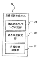
- FIG. 1 is a block configuration diagram of a travel control device 10 according to the embodiment.
- the travel control device 10 is a device mounted on a vehicle, and is a device that autonomously controls the travel of the vehicle along a route (route) from a starting point to a destination calculated using a navigation technique or the like. .
- the travel control device 10 divides the course from the departure point to the destination into predetermined sections, and the target representing the vehicle travel trajectory and vehicle behavior (for example, vehicle speed, acceleration, steering angle, etc.) for each section.
- the route is updated, and the travel control of the vehicle is performed based on the target route.
- the travel control device 10 includes a target route generation ECU (Electronic Control Unit) 12 and a travel control ECU 14. As shown in FIG. 1, the traveling control device 10 is electrically connected to a radar 16, a camera 18, a traveling state detection sensor 20, an operation state detection sensor 22, a navigation system 24, and the like. Further, a travel control actuator 26 is electrically connected to the travel control device 10.
- the travel control device 10 may be connected to other known configurations as appropriate, for example, a communication unit for performing inter-vehicle communication.
- the target route generation ECU 12 and the travel control ECU 14 are electronic control units each including a CPU (Central Processing Unit) and a memory such as a ROM (Read Only Memory) and a RAM (Random Access Memory).
- the target route generation ECU 12 acquires the route and map information from the departure point to the destination searched by the navigation system 24, and for each predetermined section set on the route, the vehicle travel locus, the vehicle behavior, etc.
- the target route representing is calculated.
- the travel control ECU 14 controls the travel of the vehicle based on the target route generated by the target route generation ECU 12.
- the travel control ECU 14 determines the own vehicle based on the target route generated by the target route generation ECU 12 and data from the radar 16, the camera 18, the travel state detection sensor 20, the operation state detection sensor 22, the navigation system 24, and the like.
- the travel control amount such as acceleration / deceleration and steering angle of the vehicle is calculated.
- the travel control ECU 14 controls the travel control actuator 26 based on the travel control amount.
- the target route generation ECU 12 and the travel control ECU 14 are described as independent ECUs, but may be configured as a single unit as appropriate.
- the Radar 16 detects the presence, position, speed, and relative speed of the vehicle, motorcycle, bicycle, pedestrian, etc. around the vehicle.
- the radar 16 includes, for example, a laser radar, a millimeter wave radar, an ultrasonic radar, and the like.
- the radar 16 outputs the detected data to the travel control device 10.
- a well-known radar may be used as appropriate, and therefore a detailed description of the configuration is omitted.
- the camera 18 is attached to the front or side of the host vehicle, for example, and takes an image around the host vehicle.
- the camera 18 images a road segment line or an obstacle on the route.
- the camera 18 includes, for example, an image sensor such as a CCD (Charge Coupled Device) or a CMOS (Complementary Metal-Oxide Semiconductor).
- the camera 18 outputs the captured image to the travel control device 10.
- a well-known camera may be used as appropriate, and thus a detailed description of the configuration is omitted.
- the traveling state sensor 20 detects the traveling state of the host vehicle (for example, vehicle speed, acceleration, yaw angle, etc.).
- the traveling state sensor 20 includes, for example, wheel speed sensors provided on the respective wheels of the host vehicle, and detects the traveling state of the host vehicle such as the vehicle speed by measuring the wheel speed.
- the traveling state sensor 20 outputs the detected traveling state of the host vehicle to the traveling control device 10. Since the well-known vehicle speed sensor, acceleration sensor, and yaw angle sensor may be used as the running state sensor 20, a description of a more detailed configuration is omitted.
- the operation state detection sensor 22 detects the operation state of the host vehicle. Specifically, the operation state detection sensor 22 detects an accelerator operation, a brake operation, a steering operation (steering), and the like by a user (hereinafter referred to as a driver) who gets on the vehicle. The operation state sensor 22 outputs the detected operation state of the host vehicle to the travel control device 10. Since the well-known accelerator operation sensor, brake operation sensor, and steering sensor may be used as the operation state sensor 22, a description of a more detailed configuration is omitted.
- the navigation system 24 receives a GPS signal from a GPS (Global Positioning System) satellite.
- the navigation system 24 includes a gyroscope that detects the magnitude of the rotational motion applied to the vehicle, an acceleration sensor that detects the travel distance of the vehicle from three-axis acceleration, and a geomagnetic sensor that detects the traveling direction of the vehicle from the geomagnetism. Etc. may be provided.
- the navigation system 24 stores map information (road information) on a recording medium such as a hard disk. This map information includes information on the location and shape of roads and intersections, traffic rules including traffic signs and signals, and the like. Further, the map information may define a travelable area of the vehicle in the lane on the road.
- the navigation system 24 detects the position of the host vehicle, the direction with respect to the road, and the like based on the GPS signal from the GPS satellite and the map information.
- the navigation system 24 searches for a route from the departure point to the destination according to the input of the departure point (or current location) and the destination, and uses the searched route and the position information of the host vehicle to reach the destination. The guidance of the route is performed.
- the navigation system 24 outputs the searched route to the travel control device 10 together with the map information. Since a known navigation system may be used as the navigation system 24, a description of a more detailed configuration is omitted.
- the traveling control actuator 26 includes an acceleration / deceleration actuator for accelerating / decelerating the host vehicle and a steering actuator for adjusting a steering angle.
- the travel control actuator 26 operates the acceleration / deceleration actuator and the steering actuator based on the travel control amount transmitted from the travel control ECU 14 to control the travel of the host vehicle.
- the target route generation ECU 12 includes a route update timing determination unit 28, an end point vehicle speed setting unit 30, and a target route calculation unit 32.
- the target route generation ECU 12 acquires the route and map information from the departure point to the destination searched by the navigation system 24, and displays the vehicle travel locus, vehicle behavior, and the like for each predetermined section set on the route.
- the target route to be expressed is calculated, and the target route is updated for each section.
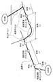
- the target route generation ECU 12 acquires map information together with the route R from the departure point to the destination searched by the navigation system 24. Then, the target route generation ECU 12 divides the route R from the departure place to the destination into predetermined sections, and updates the target path for each section. In the present embodiment, for example, sections are set by dividing the course R every 200 m.
- the method of dividing the section is not limited to this distance, and may be a distance different from this distance. Moreover, it is not necessary to divide all the sections at the same distance, and the division method may be changed as necessary.
- FIG. 3 some continuous sections divided in this way are shown as a section L0, a section L1, a section L2, a section L3,.
- a route update point for updating the target route is set.
- the route update points in the sections L0, L1, and L2 are shown as route update points C0, C1, and C2, respectively.
- the target route generation ECU 12 calculates the target route from the route update point to the end point of the next section and updates the target route. Do.
- the target route generation ECU 12 starts from the route update point C1 to the end point E1 of the section L1 and the end point E1 of the section L1 (start point of the section L2).
- the target route to the end point E2 of L2 is calculated, and the currently used target route is updated to the newly calculated target route.
- the same target route is updated in the section L2.
- the target route generation ECU 12 starts from the route update point C2 to the end point E2 of the section L2 and the end point E2 of the section L2 (start point of the section L3) to the section L3.
- the target route calculated at the route update point C1 in the section L1 is updated to the newly calculated target route.
- the route update point is set to a position that is a predetermined distance before the end point of the section (that is, a position where the remaining distance of the section is the predetermined distance).
- the predetermined distance is set to 50 m.
- the position of the route update point is not limited to this position, and may be a position different from this position.
- the route update point may be set at a position where the remaining time until the vehicle reaches the end point of the section is equal to or less than a predetermined time.
- the target route generation ECU 12 of the present embodiment allows the vehicle to travel at an appropriate vehicle speed even when the calculation of a new target route does not end at the route update point due to the time required for calculating the target route at the route update point. It is a device that sets the vehicle speed at the end point of the section so that traveling is controlled.
- the operations of the route update timing determination unit 28, the end vehicle speed setting unit 30 and the target route calculation unit 32 of the target route generation ECU 12 of this embodiment, and the operation of the travel control ECU 14 will be described.
- generation of a target route at the route update point C1 in the section L1 will be described, but similar target routes are generated in other sections.
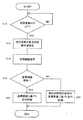
- the route update timing determination unit 28 determines whether or not the route update point C1 of the currently traveling section L1 has been passed based on the position information of the own vehicle obtained from the navigation system 24 or the like (step S10). When the route update timing determination unit 28 determines that the route update point C1 has been passed (YES in step S10), the end point vehicle speed setting unit 30 sets the target vehicle speed at the end point E2 of the next section L2 (step S12).
- the target vehicle speed at the end point E2 of the section L2 is set based on the map information of the section L3 that is a section after the end point E2.
- the end vehicle speed setting unit 30 acquires data such as the required deceleration amount at the stop point, the deceleration point, and the deceleration point included in the section L3 based on the map information obtained from the navigation system 24 and the like.
- the target vehicle speed at the end point E2 of the section L2 is set according to the data.
- the end point vehicle speed setting unit 30 sets the target vehicle speed at the end point E2 of the section L2 to 0 ( Stop).
- the target vehicle speed may not be given as a value of the vehicle speed (that is, 0), but may be given as a deceleration (in this case, 100% deceleration).
- the end vehicle speed setting unit 30 determines the necessary deceleration amount at these deceleration points. For example, if the section L3 includes a deceleration point where the speed limit decreases from 60 km / h to 40 km / h, the target vehicle speed at the end point of the section L2 is set to 40 km / h.
- a predetermined vehicle speed set in advance according to the curvature of the intersection or the curve is set as the target vehicle speed.
- the predetermined vehicle speed is stored in advance in the memory of the target route generation ECU 12 or the like so that the predetermined vehicle speed decreases as the curvature increases.
- the target vehicle speed may not be given as a value of the vehicle speed, but may be given as a deceleration (for example, 40% deceleration).
- the target vehicle speed at the end point E2 of the section L2 may be set to 0 (stop). Moreover, when the section L3 includes a plurality of deceleration points, the smallest target vehicle speed among the target vehicle speeds of these deceleration points may be set as the target vehicle speed.
- the end point car setting unit 30 determines that the deceleration / stop at the end point E2 of the section L2 is not necessary.
- the target vehicle speed is given as a deceleration (in this case, 0% deceleration).
- the end vehicle speed setting unit 30 determines whether the section L3 includes a stop point or a deceleration point based on map information obtained from the navigation system 24 or the like. It may be determined whether the section L3 includes a stop point or a deceleration point by a method. For example, it may be determined whether the section L3 includes a stop point or a deceleration point based on data that can be acquired from the radar 16 or the camera 18. Moreover, in this embodiment, although it determines whether the area L3 contains a stop point and a deceleration point, the area as a determination object is not restricted to this. For example, it may not be the entire section L3. For example, a section of a predetermined distance after the end point E2 of the section L2 that is a part of the section L3 may be set as the determination target.
- the target vehicle speed (or deceleration) at the end point E2 of the section L2 set as described above is set as the target vehicle speed Vn at the end point of the next section, separately from the target vehicle speed Vp at the end point of the current section. Saved in memory etc.
- the target vehicle speed at the end point of the next section (for example, the target vehicle speed at the end point E2 of the section L2) is set in step S12
- the target vehicle speed stored as the target vehicle speed Vn at the end point of the next section (for example, The target vehicle speed of the end point E1 of the section L1 set at the route update point C0 of the section L0) is saved again as the target vehicle speed Vp of the end point of the current section, and the target vehicle speed of the end point of the next section set newly is It is stored as the target vehicle speed Vn at the end point of the next section.
- the target route calculation unit 32 starts calculating a new target route (step S14). Specifically, the target route calculation unit 32 calculates a target route from the route update point C1 to the end point E1 of the section L1 and the end point E1 of the section L1 (start point of the section L2) to the end point E2 of the section L2. For example, the target route calculation unit 32 generates a time function (vehicle speed profile) of the target vehicle speed starting from the actual vehicle speed of the vehicle at the route update point C1. This vehicle speed profile is stored in a memory or the like as a new target route along with a time function (steering profile) of the target travel locus and target steering amount generated separately, and the currently used target route is updated.
- a time function vehicle speed profile
- the target route calculation unit 32 generates the vehicle speed profile in consideration of the map information of the next section L2 acquired from the navigation system 24, similarly to the calculation of the known target route. Similarly, the target route calculation unit 32 generates a target travel locus and a steering profile based on the map information of the next section L2 acquired from the navigation system 24, similarly to the known target route calculation. For example, in such calculation of the target route, according to the curvature of the route obtained from the map information, the target travel locus, the vehicle speed profile, the steering profile, and the like such that the lateral acceleration applied to the vehicle is 0.2 G or less. A route is generated.
- the target route calculation unit 32 determines whether or not the target route has been updated (step S16). Specifically, it is determined whether the calculation is completed within a predetermined time from the start of the calculation of the new target route in step S14 and the update of the target route is completed.
- the predetermined time is set to 0.5 seconds, for example, but the predetermined time is not limited to this value, and may be a value different from this value.
- step S16 If it is determined that the target route has been updated (YES in step S16), the travel control ECU 14 performs vehicle travel control based on the new target route stored in the memory of the target route generation ECU 12 or the like (step S16). S18).
- the traveling control ECU 14 ends the current section stored in the memory of the target route generation ECU 12 or the like. Is acquired as the target vehicle speed at the end point E1 of the section L1 (step S20).
- Examples of cases where the calculation and update of the target route do not end within a predetermined time include, for example, when map information from the navigation system 24 cannot be acquired properly, or there are many intersections and curves in the section from the route update point C1 to the end point E2. For example, the map information is complicated and it takes time to calculate.
- the traveling control ECU 14 performs traveling control of the vehicle based on the acquired target vehicle speed Vp at the end point of the current section (step S20). Specifically, the travel control ECU 14 performs vehicle travel control so that the vehicle speed smoothly reaches the target vehicle speed Vp at the end point E1 of the section L1, starting from the actual vehicle speed of the current vehicle.
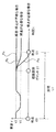
- FIG. 5 shows vehicle travel control in the section L1 (section from the end point E0 of the section L0 to the end point E1 of the section L1) by the travel control device 10 of the present embodiment.
- the target route target vehicle speed
- the vehicle travel control is performed based on the target vehicle speed of the end point E1 of the section L1 set at the route update point C0 of the section L0. Done.
- step S12 in the setting of the target vehicle speed of the end point E1 of the section L1 executed at the route update point C0 of the section L0 (step S12), if it is determined that the stop is necessary at the end point E1 of the section L1, the section L1 Travel control is performed so that the vehicle speed becomes 0 (stop) at the end point E1 (see vehicle speed profile Pa). Further, for example, in the setting of the target vehicle speed, when it is determined that deceleration to the vehicle speed V1 is necessary at the end point E1 of the section L1, the travel control is performed so that the vehicle speed is reduced to V1 at the end point E1 of the section L1. Is performed (see vehicle speed profile Pb).
- the target vehicle speed at the end point of the next section is set based on the stop point and the deceleration point of the section after the end point. For this reason, unnecessary deceleration can be prevented, and it is possible to reduce the uncomfortable feeling that the user feels when updating the target route.
- the target route generation ECU 12 (target route generation device) sets the target route for controlling the vehicle traveling in a predetermined section (for example, the section L2) as a route update point (predetermined point).
- the target vehicle speed used when the target route calculation unit 32 (generation unit) generated at the timing of (3) and the target route calculation unit 32 (generation unit) cannot generate the target route at the route update point (predetermined timing).
- An end point vehicle speed setting unit 30 (setting unit) for presetting a target vehicle speed at an end point (for example, end point E1) (section end point) of a section in which the vehicle is currently traveling (for example, section L1).
- the unit 30 sets the target vehicle speed based on the map information (road information) in a predetermined section (for example, the section L2). Accordingly, it is possible to provide a target route generation ECU 12 (target route generation device) that reduces a sense of discomfort that the user feels when updating the target route.
- the target route generation ECU 12 (target route generation device) reaches the position before the end point of the section or the end point of the section based on the position information of the vehicle by a predetermined distance of the end point of the section (for example, the end point E1 of the section L1).
- a route update timing determination unit 28 (determination unit) that determines a timing at which a remaining time until a position (predetermined position) where the remaining time is equal to or less than a predetermined time as a route update point (predetermined timing) may be further provided. Thereby, a target route can be generated at a timing when the vehicle reaches a predetermined position.
- the predetermined section (for example, the section L2) includes a section next to the section in which the vehicle is currently traveling (for example, the section L1), and the target path calculation unit 32
- the (generation unit) has a predetermined remaining time until the vehicle reaches the position or the end point of a section that is a short distance from the end point (for example, the end point E1 of the section L1) of the section where the vehicle is currently traveling (for example, the end point E1 of the section L1).
- a target route for a predetermined section (for example, section L2) may be generated.
- the target route of the next section can be generated at the timing when the vehicle reaches the predetermined position of the section where the vehicle is currently traveling.
- the end vehicle speed setting unit 30 (setting unit) travels in a section (for example, section L0) before the section (for example, section L1) in which the vehicle is currently traveling.
- the target vehicle speed may be set while the vehicle is running. Thereby, even when the target route calculation unit 32 (generation unit) cannot generate the target route at the route update point (predetermined timing), the target vehicle speed set in advance in the previous section can be used.
- the end point vehicle speed setting unit 30 (setting unit) is used as a vehicle stop point or deceleration point in a predetermined section (for example, section L2) in the map information (road information). Based on this, the target vehicle speed may be set in advance. Thereby, the target vehicle speed at the section end point of the currently traveling section can be appropriately set according to the stop point or the deceleration point of the vehicle in the predetermined section.
- the travel control apparatus 10 controls the travel of the vehicle based on the target route generation ECU 12 (target vehicle speed generation device) and the target route generated by the target route generation ECU 12. And a control ECU 14 (control device). Accordingly, it is possible to provide the travel control device 10 that reduces a sense of discomfort felt by the user when updating the target route.
- the travel control ECU 14 sets the target vehicle speed when the target route calculation unit 32 (generation unit) cannot generate the target route at the route update point (predetermined timing) (NO in step S16 in FIG. 4). Based on this, traveling of the vehicle may be controlled. Thus, even when the target route calculation unit 32 (generation unit) cannot generate the target route at the route update point (predetermined timing), the traveling of the vehicle can be controlled based on the preset target vehicle speed.
- the travel control ECU 14 determines at least the end point (for example, end point E1) of the section (for example, section L1) in which the vehicle is currently traveling based on the target vehicle speed (for example, the vehicle speed profile Pa, Pb, Pc) ( The traveling of the vehicle up to the end point of the section may be controlled.
- the target route calculation unit 32 generation unit
- the traveling of the vehicle can be controlled based on a preset target vehicle speed.
- the travel control ECU 14 controls the travel of the vehicle in at least a part of a predetermined section (for example, the section L2) based on the target vehicle speed (for example, the vehicle speed profile Pa, Pb, Pc). Also good.
- the target route calculation unit 32 generation unit
- the end point for example, the section L1 in which the vehicle is currently traveling (for example, the section L1)
- the end point E1) section end point
- the travel of the vehicle can be controlled based on a preset target vehicle speed.
- the travel control ECU 14 when the target route calculation unit 32 (generation unit) cannot generate the target route within a predetermined time at the route update point (predetermined timing) (NO in step S16 of FIG. 4).
- the traveling of the vehicle may be controlled based on the target vehicle speed. Thereby, it is possible to easily determine the case where the target route calculation unit 32 (generation unit) cannot generate the target route at the route update point (predetermined timing).
- step S10 when it is determined that the route update point has been passed (YES in step S10), the target vehicle speed is set (step S12) and the target route is calculated (step S14). Yes. Further, after the calculation of the target route is started, it is determined whether or not the calculation is completed within a predetermined time (step S16). However, a route update start point may be set in advance at a position separated from the route update point by a predetermined distance before the route update point. In this case, when it is determined that the vehicle has passed the route update start point, setting of the target vehicle speed (step S12) and calculation of the target route (step S14) are started, and is the target route updated at the route update point?
- step S16 it is determined (step S16). In this case, after the vehicle has passed the route update start point, it is determined whether or not the calculation of the target route has been completed within a predetermined time. In addition to updating to the newly calculated target route, when the calculation of the target route is not completed, travel control based on the set target vehicle speed may be performed at the route update point.
- step S12 After setting the target vehicle speed Vn at the end point of the next section (step S12), calculation of the target route (step S14) and determination of whether or not the target route has been updated. (Step S16), travel control based on the target route (Step S18), and travel control based on the target vehicle speed Vp at the end point of the current section (Step S20) are performed. However, the order of these processes may be changed as appropriate.
- step S14 calculation of a target route (step S14), determination of whether the target route has been updated (step S16), travel control based on the target route (step S18), and travel control based on the target vehicle speed at the end point of the current section ( The process of step S20) may be performed before the setting of the target vehicle speed at the end point of the next section (step S12).
- step S20 the travel control ECU 14 reads the target vehicle speed at the end point of the current section stored in the memory of the target route generation ECU 12, and the end point
- the vehicle speed setting unit 30 sets the target vehicle speed at the end point of the next section (step S12).
- the vehicle when setting the target vehicle speed for the end point E2 of the next section L2, if the section L3 includes a deceleration point, the vehicle is decelerated so as to have a predetermined vehicle speed at the end point E2 of the section L2. I do.
- the degree of deceleration may be changed according to the position of this deceleration point in the section L3. For example, when the deceleration point is separated from the end point E2 by a predetermined distance or more, the degree of deceleration may be decreased so that the vehicle speed is higher than the predetermined vehicle speed at the end point E2 of the section L2. Further, the degree of deceleration to the end point E2 of the section L2 may be reduced as the distance from the end point E2 to the deceleration point increases.
- the end point vehicle speed setting unit 30 sets the end point of the section (for example, the end point E1 of the section L1 or the end point E2 of the section L2) (section
- the target vehicle speed may be set in advance based on the distance from the end point) to a stop point or deceleration point of the vehicle in a predetermined section (for example, section L2 or section L3).
- the target vehicle speed at the end point of the currently traveling section can be appropriately set according to the distance from the end point of the section to the stop point or deceleration point of the vehicle in the predetermined section.
- step S16 when it is determined that the calculation and update of the target route has not ended within a predetermined time (NO in step S16), the traveling control ECU 14 determines the current section. Vehicle travel control is performed based on the target vehicle speed Vp at the end point (step S20). At this time, when it is determined that the calculation and update of the target route are not completed within the predetermined time (NO in step S16), the calculation of the target route by the target route calculating unit 32 may be stopped, The calculation of the target route by the route calculation unit 32 may be continued.
- the traveling control ECU 14 decelerates to the end point of the section according to the remaining time.
- the degree may be changed. For example, when the remaining time is shorter than a predetermined time (for example, 1 second), even if the target vehicle speed Vp at the end point of the current section is 0 (stopped), it is less than the degree of deceleration when the vehicle is stopped.
- the vehicle traveling control may be performed with a small degree of deceleration. That is, when the remaining time is shorter than the predetermined time, the vehicle travel control may be performed with a deceleration degree smaller than the deceleration degree when the vehicle is decelerated to the target vehicle speed Vp at the end point of the current section.
- the travel control ECU 14 (control device) is configured so that the target route calculation unit 32 (generation unit) cannot generate the target route at the route update point (predetermined timing) (step of FIG. 4).
- the target route calculation unit 32 generation unit
- the target vehicle speed is set to a deceleration degree smaller than the deceleration degree when decelerating to the target vehicle speed. May be changed to control the running of the vehicle.
- the vehicle travel can be controlled by changing the target vehicle speed so as to reduce the uncomfortable feeling felt by the user when updating to the target route.
- the end vehicle speed setting unit 30 sets the target vehicle speed at the end point E2 of the next section L2 (step S12).
- the target vehicle speed set by the end point vehicle speed setting unit 30 may be set as a vehicle speed value at the end point E2 of the section L2, or may be set as a time function (vehicle speed profile) of the vehicle speed up to the end point E2 of the section L2. Good.
- the end vehicle speed setting unit 30 When the target vehicle speed is set as the vehicle speed profile, the end vehicle speed setting unit 30 generates a vehicle speed profile (for example, any one of the vehicle speed profiles Pa, Pb, and Pc shown in FIG. 5) in step S12.
- the traveling control ECU 14 performs traveling control of the vehicle based on the generated vehicle speed profile.
- the end vehicle speed setting unit 30 may generate a vehicle speed profile (for example, any one of the vehicle speed profiles Pa, Pb, and Pc shown in FIG. 5) based on the value of the vehicle speed.
- the travel control ECU 14 performs vehicle travel control based on the generated vehicle speed profile.
- the target route calculation unit 32 sets the target route from the route update point C1 of the section L1 to the end point E2 of the section L2 in step S14.
- the target route may be calculated based on the vehicle speed value. In this case, if the calculation and update of the target route from the route update point C2 of the section L2 to the end point of the section L3 is not completed in the section L2, the vehicle travel control is continued based on the currently used target route.
- the autonomous traveling control by the traveling control ECU 14 is performed, but the generation of the target route of the present application is also used when complete autonomous traveling control is not performed or when autonomous traveling control is not performed at all. be able to.
- the target route generated by the target route generation ECU 12 may be simply notified to the driver, or the driving condition for achieving the generated target route may be notified to the user.
- driving assistance that supports driving of the user (driver) is performed.
- driving assistance can also be performed by performing only acceleration / deceleration or performing only steering by the traveling control device 10.
Landscapes
- Engineering & Computer Science (AREA)
- Remote Sensing (AREA)
- Radar, Positioning & Navigation (AREA)
- Physics & Mathematics (AREA)
- Automation & Control Theory (AREA)
- General Physics & Mathematics (AREA)
- Transportation (AREA)
- Mechanical Engineering (AREA)
- Combustion & Propulsion (AREA)
- Chemical & Material Sciences (AREA)
- Mathematical Physics (AREA)
- Aviation & Aerospace Engineering (AREA)
- Computer Vision & Pattern Recognition (AREA)
- Atmospheric Sciences (AREA)
- Multimedia (AREA)
- Electromagnetism (AREA)
- Life Sciences & Earth Sciences (AREA)
- Human Computer Interaction (AREA)
- Control Of Driving Devices And Active Controlling Of Vehicle (AREA)
- Navigation (AREA)
- Traffic Control Systems (AREA)
- Business, Economics & Management (AREA)
- Health & Medical Sciences (AREA)
- Artificial Intelligence (AREA)
- Evolutionary Computation (AREA)
- Game Theory and Decision Science (AREA)
- Medical Informatics (AREA)
- Train Traffic Observation, Control, And Security (AREA)
- Electric Propulsion And Braking For Vehicles (AREA)
- Control Of Vehicle Engines Or Engines For Specific Uses (AREA)
- Controls For Constant Speed Travelling (AREA)
Abstract
Priority Applications (9)
| Application Number | Priority Date | Filing Date | Title |
|---|---|---|---|
| EP15876736.8A EP3243686B1 (fr) | 2015-01-05 | 2015-06-30 | Dispositif de génération d'itinéraire cible, et dispositif de commande d'entraînement |
| US15/538,503 US10001782B2 (en) | 2015-01-05 | 2015-06-30 | Target pathway generating device and driving control device |
| BR112017014516-2A BR112017014516B1 (pt) | 2015-01-05 | 2015-06-30 | Dispositivo de controle de condução |
| MX2017008861A MX358047B (es) | 2015-01-05 | 2015-06-30 | Dispositivo de generacion de ruta objetivo y dispositivo de control de conduccion. |
| JP2016568154A JP6315107B2 (ja) | 2015-01-05 | 2015-06-30 | 目標経路生成装置および走行制御装置 |
| KR1020177018260A KR101850669B1 (ko) | 2015-01-05 | 2015-06-30 | 목표 주행 정보 생성 장치 및 주행 제어 장치 |
| RU2017127528A RU2671602C1 (ru) | 2015-01-05 | 2015-06-30 | Устройство формирования целевого маршрута и устройство управления приведением в движение |
| CN201580072318.3A CN107107750B (zh) | 2015-01-05 | 2015-06-30 | 目标路径生成装置及行驶控制装置 |
| CA2973113A CA2973113C (fr) | 2015-01-05 | 2015-06-30 | Dispositif de generation d'itineraire cible, et dispositif de commande d'entrainement |
Applications Claiming Priority (2)
| Application Number | Priority Date | Filing Date | Title |
|---|---|---|---|
| US201562099631P | 2015-01-05 | 2015-01-05 | |
| US62/099,631 | 2015-01-05 |
Publications (1)
| Publication Number | Publication Date |
|---|---|
| WO2016110733A1 true WO2016110733A1 (fr) | 2016-07-14 |
Family
ID=56355564
Family Applications (1)
| Application Number | Title | Priority Date | Filing Date |
|---|---|---|---|
| PCT/IB2015/001087 Ceased WO2016110733A1 (fr) | 2015-01-05 | 2015-06-30 | Dispositif de génération d'itinéraire cible, et dispositif de commande d'entraînement |
Country Status (10)
| Country | Link |
|---|---|
| US (1) | US10001782B2 (fr) |
| EP (1) | EP3243686B1 (fr) |
| JP (1) | JP6315107B2 (fr) |
| KR (1) | KR101850669B1 (fr) |
| CN (1) | CN107107750B (fr) |
| BR (1) | BR112017014516B1 (fr) |
| CA (1) | CA2973113C (fr) |
| MX (1) | MX358047B (fr) |
| RU (1) | RU2671602C1 (fr) |
| WO (1) | WO2016110733A1 (fr) |
Cited By (2)
| Publication number | Priority date | Publication date | Assignee | Title |
|---|---|---|---|---|
| CN108973681A (zh) * | 2017-05-31 | 2018-12-11 | 丰田自动车株式会社 | 车辆控制装置 |
| RU2707855C1 (ru) * | 2017-11-17 | 2019-11-29 | Тойота Дзидося Кабусики Кайся | Система автономного вождения (варианты) |
Families Citing this family (12)
| Publication number | Priority date | Publication date | Assignee | Title |
|---|---|---|---|---|
| JP6972744B2 (ja) * | 2017-08-01 | 2021-11-24 | トヨタ自動車株式会社 | 運転支援装置 |
| CN109960255B (zh) * | 2017-12-26 | 2022-02-18 | 郑州宇通客车股份有限公司 | 一种最优目标车速预测、燃料电池系统的控制方法及装置 |
| JP6881609B2 (ja) * | 2017-12-27 | 2021-06-02 | 日産自動車株式会社 | 車両管理システム、車両管理装置、及び車両管理方法 |
| GB201802475D0 (en) * | 2018-02-15 | 2018-04-04 | Jaguar Land Rover Ltd | Controller and vehicle |
| EP3530538B1 (fr) * | 2018-02-26 | 2022-11-23 | Toyota Jidosha Kabushiki Kaisha | Système de commande de véhicule et procédé de commande de véhicule |
| KR102518600B1 (ko) * | 2018-10-26 | 2023-04-06 | 현대자동차 주식회사 | 친환경 차량의 감속 제어 방법 |
| JP7206970B2 (ja) * | 2019-02-04 | 2023-01-18 | 日産自動車株式会社 | 車両運動制御方法及び車両運動制御装置 |
| FR3093689B1 (fr) * | 2019-03-12 | 2021-04-09 | Renault | Procédé d’élaboration d’une consigne de pilotage mixte d’un système de braquage de roues et d’un système de freinage différentiel d’un véhicule automobile |
| JP7319867B2 (ja) * | 2019-08-23 | 2023-08-02 | 株式会社東芝 | 無線通信システム、無線通信装置、及び無線通信方法 |
| CN111210647B (zh) * | 2020-01-18 | 2021-01-19 | 杭州后博科技有限公司 | 一种基于智慧灯杆的行进控制方法及系统 |
| FR3116500B1 (fr) * | 2020-11-24 | 2023-02-17 | Renault Sas | Procédé de pilotage automatisé d’un véhicule automobile |
| JP7510446B2 (ja) * | 2022-01-24 | 2024-07-03 | 本田技研工業株式会社 | 経路生成装置 |
Citations (3)
| Publication number | Priority date | Publication date | Assignee | Title |
|---|---|---|---|---|
| JPH07117524A (ja) * | 1993-10-29 | 1995-05-09 | Isuzu Motors Ltd | 車両走行制御装置 |
| JP2004322764A (ja) * | 2003-04-23 | 2004-11-18 | Nissan Motor Co Ltd | 自動速度制御装置 |
| JP2010188950A (ja) * | 2009-02-20 | 2010-09-02 | Hitachi Automotive Systems Ltd | 車両走行制御装置 |
Family Cites Families (10)
| Publication number | Priority date | Publication date | Assignee | Title |
|---|---|---|---|---|
| US8996294B2 (en) | 2007-12-19 | 2015-03-31 | Nissan Motor Co., Ltd. | Inter-vehicle distance maintenance supporting system and method |
| JP2011240816A (ja) | 2010-05-18 | 2011-12-01 | Denso Corp | 自律走行制御装置 |
| DE112011105832B4 (de) * | 2011-11-10 | 2016-12-01 | Mitsubishi Electric Corp. | Fahrzeugseitiges System |
| JP6128584B2 (ja) * | 2013-01-16 | 2017-05-17 | 株式会社Soken | 走行経路生成装置 |
| KR101461880B1 (ko) * | 2013-03-18 | 2014-11-14 | 현대자동차 주식회사 | 차량의 주행 정보 제공 방법 및 시스템 |
| DE102013005248A1 (de) * | 2013-03-27 | 2014-10-02 | Conti Temic Microelectronic Gmbh | Verfahren und Vorrichtung für einen Überholassistenten |
| DE102013009279A1 (de) * | 2013-06-04 | 2014-12-04 | Daimler Ag | Verfahren und Vorrichtung zum Betrieb eines Hybridantriebsstrangs eines Fahrzeugs |
| JP5786899B2 (ja) * | 2013-06-12 | 2015-09-30 | トヨタ自動車株式会社 | 操舵補助表示装置 |
| JP6369061B2 (ja) * | 2014-03-13 | 2018-08-08 | 日産自動車株式会社 | 車線変更支援装置 |
| JP6297956B2 (ja) * | 2014-05-13 | 2018-03-20 | 株式会社Soken | 経路生成装置 |
-
2015
- 2015-06-30 MX MX2017008861A patent/MX358047B/es active IP Right Grant
- 2015-06-30 EP EP15876736.8A patent/EP3243686B1/fr active Active
- 2015-06-30 RU RU2017127528A patent/RU2671602C1/ru active
- 2015-06-30 JP JP2016568154A patent/JP6315107B2/ja active Active
- 2015-06-30 KR KR1020177018260A patent/KR101850669B1/ko not_active Expired - Fee Related
- 2015-06-30 US US15/538,503 patent/US10001782B2/en active Active
- 2015-06-30 BR BR112017014516-2A patent/BR112017014516B1/pt active IP Right Grant
- 2015-06-30 CN CN201580072318.3A patent/CN107107750B/zh active Active
- 2015-06-30 CA CA2973113A patent/CA2973113C/fr active Active
- 2015-06-30 WO PCT/IB2015/001087 patent/WO2016110733A1/fr not_active Ceased
Patent Citations (3)
| Publication number | Priority date | Publication date | Assignee | Title |
|---|---|---|---|---|
| JPH07117524A (ja) * | 1993-10-29 | 1995-05-09 | Isuzu Motors Ltd | 車両走行制御装置 |
| JP2004322764A (ja) * | 2003-04-23 | 2004-11-18 | Nissan Motor Co Ltd | 自動速度制御装置 |
| JP2010188950A (ja) * | 2009-02-20 | 2010-09-02 | Hitachi Automotive Systems Ltd | 車両走行制御装置 |
Non-Patent Citations (1)
| Title |
|---|
| See also references of EP3243686A4 * |
Cited By (4)
| Publication number | Priority date | Publication date | Assignee | Title |
|---|---|---|---|---|
| CN108973681A (zh) * | 2017-05-31 | 2018-12-11 | 丰田自动车株式会社 | 车辆控制装置 |
| CN108973681B (zh) * | 2017-05-31 | 2021-09-21 | 丰田自动车株式会社 | 车辆控制装置 |
| RU2707855C1 (ru) * | 2017-11-17 | 2019-11-29 | Тойота Дзидося Кабусики Кайся | Система автономного вождения (варианты) |
| US11768500B2 (en) | 2017-11-17 | 2023-09-26 | Toyota Jidosha Kabushiki Kaisha | Autonomous driving system |
Also Published As
| Publication number | Publication date |
|---|---|
| EP3243686A4 (fr) | 2018-08-08 |
| US10001782B2 (en) | 2018-06-19 |
| RU2671602C1 (ru) | 2018-11-02 |
| MX2017008861A (es) | 2017-10-25 |
| KR20170085134A (ko) | 2017-07-21 |
| EP3243686A1 (fr) | 2017-11-15 |
| BR112017014516B1 (pt) | 2023-01-17 |
| EP3243686B1 (fr) | 2021-05-26 |
| JP6315107B2 (ja) | 2018-04-25 |
| CN107107750A (zh) | 2017-08-29 |
| CN107107750B (zh) | 2019-10-01 |
| MX358047B (es) | 2018-08-03 |
| CA2973113C (fr) | 2019-03-05 |
| JPWO2016110733A1 (ja) | 2017-10-26 |
| CA2973113A1 (fr) | 2016-07-14 |
| BR112017014516A2 (pt) | 2018-01-16 |
| KR101850669B1 (ko) | 2018-05-31 |
| US20170351262A1 (en) | 2017-12-07 |
Similar Documents
| Publication | Publication Date | Title |
|---|---|---|
| JP6315107B2 (ja) | 目標経路生成装置および走行制御装置 | |
| JP6323572B2 (ja) | 目標車速生成装置および走行制御装置 | |
| JP6447639B2 (ja) | 目標経路生成装置および走行制御装置 | |
| JP6573222B2 (ja) | 車両制御装置 | |
| CN111247045A (zh) | 车辆控制装置 | |
| CN111433094A (zh) | 车辆控制装置 | |
| CN111527015A (zh) | 车辆控制装置 | |
| JP6647681B2 (ja) | 車両制御装置 | |
| US12084109B2 (en) | Vehicle control device | |
| JP2018203108A (ja) | 車両制御装置 | |
| WO2016110732A1 (fr) | Dispositif de génération de trajet cible et dispositif de commande de déplacement | |
| CN114364592A (zh) | 用于自动驾驶车辆的轨迹形状生成的方法和装置 | |
| JP7463264B2 (ja) | 車両運動制御装置、および、車両運動制御方法 | |
| JP6376522B2 (ja) | 車両制御装置 | |
| JP6288305B2 (ja) | 目標車速生成装置および走行制御装置 | |
| JP6572948B2 (ja) | 車両制御装置 | |
| JP6376521B2 (ja) | 車両制御装置 | |
| JP2020124994A (ja) | 車両運動制御方法及び車両運動制御装置 |
Legal Events
| Date | Code | Title | Description |
|---|---|---|---|
| 121 | Ep: the epo has been informed by wipo that ep was designated in this application |
Ref document number: 15876736 Country of ref document: EP Kind code of ref document: A1 |
|
| ENP | Entry into the national phase |
Ref document number: 2016568154 Country of ref document: JP Kind code of ref document: A |
|
| WWE | Wipo information: entry into national phase |
Ref document number: 15538503 Country of ref document: US |
|
| ENP | Entry into the national phase |
Ref document number: 20177018260 Country of ref document: KR Kind code of ref document: A |
|
| WWE | Wipo information: entry into national phase |
Ref document number: MX/A/2017/008861 Country of ref document: MX |
|
| ENP | Entry into the national phase |
Ref document number: 2973113 Country of ref document: CA |
|
| NENP | Non-entry into the national phase |
Ref country code: DE |
|
| REG | Reference to national code |
Ref country code: BR Ref legal event code: B01A Ref document number: 112017014516 Country of ref document: BR |
|
| REEP | Request for entry into the european phase |
Ref document number: 2015876736 Country of ref document: EP |
|
| ENP | Entry into the national phase |
Ref document number: 2017127528 Country of ref document: RU Kind code of ref document: A |
|
| ENP | Entry into the national phase |
Ref document number: 112017014516 Country of ref document: BR Kind code of ref document: A2 Effective date: 20170705 |