WO2016110930A1 - Dispositif de climatisation - Google Patents
Dispositif de climatisation Download PDFInfo
- Publication number
- WO2016110930A1 WO2016110930A1 PCT/JP2015/050008 JP2015050008W WO2016110930A1 WO 2016110930 A1 WO2016110930 A1 WO 2016110930A1 JP 2015050008 W JP2015050008 W JP 2015050008W WO 2016110930 A1 WO2016110930 A1 WO 2016110930A1
- Authority
- WO
- WIPO (PCT)
- Prior art keywords
- heat exchanger
- fins
- boss portion
- tube
- air conditioner
- Prior art date
- Legal status (The legal status is an assumption and is not a legal conclusion. Google has not performed a legal analysis and makes no representation as to the accuracy of the status listed.)
- Ceased
Links
Images




Classifications
-
- F—MECHANICAL ENGINEERING; LIGHTING; HEATING; WEAPONS; BLASTING
- F24—HEATING; RANGES; VENTILATING
- F24F—AIR-CONDITIONING; AIR-HUMIDIFICATION; VENTILATION; USE OF AIR CURRENTS FOR SCREENING
- F24F1/00—Room units for air-conditioning, e.g. separate or self-contained units or units receiving primary air from a central station
- F24F1/06—Separate outdoor units, e.g. outdoor unit to be linked to a separate room comprising a compressor and a heat exchanger
- F24F1/14—Heat exchangers specially adapted for separate outdoor units
-
- F—MECHANICAL ENGINEERING; LIGHTING; HEATING; WEAPONS; BLASTING
- F28—HEAT EXCHANGE IN GENERAL
- F28F—DETAILS OF HEAT-EXCHANGE AND HEAT-TRANSFER APPARATUS, OF GENERAL APPLICATION
- F28F1/00—Tubular elements; Assemblies of tubular elements
- F28F1/10—Tubular elements and assemblies thereof with means for increasing heat-transfer area, e.g. with fins, with projections, with recesses
- F28F1/12—Tubular elements and assemblies thereof with means for increasing heat-transfer area, e.g. with fins, with projections, with recesses the means being only outside the tubular element
- F28F1/34—Tubular elements and assemblies thereof with means for increasing heat-transfer area, e.g. with fins, with projections, with recesses the means being only outside the tubular element and extending obliquely
Definitions
- the present invention relates to an air conditioner including a heat exchanger.
- Patent Document 1 discloses an outdoor unit of an air conditioner that includes a heat exchanger having a flat plate-shaped heat exchanging part arranged in a lateral direction of a housing and a blower arranged to face the heat exchanging part. Yes.
- the heat exchanger when the heat exchanger is viewed from the direction of the rotation axis of the propeller fan of the blower, the heat exchange part has a substantially square shape.
- Patent Document 1 attempts to save energy by suppressing variations in wind speed distribution in the heat exchange section, increasing the heat exchange amount per unit area. Further, Patent Document 1 intends to save resources by increasing the heat exchange amount without increasing the volume of the heat exchange section.
- the present invention has been made against the background of the above problems, and provides an air conditioner that improves the heat exchange efficiency of the heat exchanger and is excellent in noise reduction.
- An air conditioner according to the present invention is provided with a casing, a plurality of fins provided in the casing and spaced apart from each other in the lateral direction, and the plurality of fins, and a heat medium flows therethrough.
- a flat plate-shaped heat exchanger having a tube, and a boss portion and an impeller that rotates around the boss portion.
- the heat exchanger is disposed inside the housing so as to face the heat exchanger, and is rotated by the rotation of the impeller. And at least a part of the plurality of fins in the heat exchanger is inclined toward the boss portion.
- the plurality of fins are inclined toward the boss portion. For this reason, the heat exchange efficiency of the heat exchanger is improved, and noise reduction can be realized.
- FIG. 1 is a circuit diagram showing an air conditioner 1 according to Embodiment 1 of the present invention.
- the air conditioner 1 will be described with reference to FIG.
- the air conditioner 1 includes a heat medium circuit 2.
- the compressor 11, the heat exchanger 13, the expansion unit 14, and the indoor heat exchanger 15 are connected by piping, and the heat medium flows.
- the heat medium circuit 2 also has, for example, a four-way switching valve 12.
- the air conditioner 1 includes a blower 13 a that is disposed to face the heat exchanger 13 and an indoor blower 15 a that is disposed to face the indoor heat exchanger 15.
- the air conditioning apparatus 1 has the outdoor unit 3 and the indoor unit 4, for example. Inside the outdoor unit 3, a compressor 11, a four-way switching valve 12, a heat exchanger 13, a blower 13 a and an expansion unit 14 are installed. Inside the indoor unit 4, an indoor heat exchanger 15 and An indoor blower 15a is installed.
- the compressor 11 compresses the refrigerant vapor and can be, for example, a scroll type.
- the four-way switching valve 12 has a first port 12a, a second port 12b, a third port 12c, and a fourth port 12d.
- the first port 12 a is connected to a discharge pipe 11 a that is a pipe on the discharge side of the compressor 11.
- the second port 12 b is connected to the indoor heat exchanger 15.
- the third port 12 c is connected to a suction pipe 11 b that is the suction side of the compressor 11.
- the fourth port 12d is connected to the heat exchanger 13.
- the four-way switching valve 12 is connected to the third port 12c and the fourth port 12d when the first port 12a and the second port 12b are connected (solid line in FIG. 1). .
- the second port 12b and the third port 12c are connected (broken line in FIG. 1). .
- the heat exchanger 13 is for exchanging heat between, for example, a heat medium flowing inside the outdoor air.
- the heat exchanger 13 includes fins 41 and tubes 42 (see FIG. 3), and the fins 41 and the tubes 42 are made of, for example, aluminum.
- the heat exchanger 13 acts as an evaporator in the heating operation, and acts as a condenser in the cooling operation.
- the blower 13 a blows outdoor air to the heat exchanger 13, for example, and discharges the outdoor air heat-exchanged with the heat medium circulating in the heat exchanger 13 to the outside of the outdoor unit 3.
- the expansion part 14 depressurizes the heat medium, and is, for example, an electronic expansion valve.
- the indoor heat exchanger 15 is for exchanging heat between, for example, a heat medium flowing inside the indoor heat exchanger 15 and indoor air.
- the indoor heat exchanger 15 has fins (not shown) and tubes (not shown), and the fins and tubes are made of, for example, aluminum.
- the indoor heat exchanger 15 acts as a condenser in the heating operation, and acts as an evaporator in the cooling operation.
- the indoor blower 15a blows indoor air to the indoor heat exchanger 15, and blows outdoor air heat-exchanged with the heat medium circulating in the indoor heat exchanger 15 from the indoor unit 4 into the room. is there.
- the heat medium is, for example, ammonia refrigerant or chlorofluorocarbon refrigerant, but is not limited thereto, and other refrigerants may be used.
- the heat medium circuit 2 is a circuit in which a vapor compression refrigeration cycle is configured by circulating a heat medium through a pipe.
- the four-way switching valve 12 is connected to the first port 12a and the second port 12b, and is connected to the third port 12c and the fourth port 12d (solid line in FIG. 1). .
- the compressor 11 sucks the heat medium, compresses the heat medium, and discharges the heat medium in a high-temperature and high-pressure gas state.
- the discharged heat medium passes through the first port 12a and the second port 12b of the four-way switching valve 12, flows into the indoor heat exchanger 15, and the indoor heat exchanger 15 is supplied from the indoor blower 15a.
- the heat medium is condensed by heat exchange with the supplied indoor air.
- the indoor blower 15a blows indoor air heated by heat exchange into the room. Thereby, the room is heated.
- the condensed heat medium flows into the expansion unit 14, and the expansion unit 14 depressurizes the condensed heat medium.
- the reduced-pressure heat medium flows into the heat exchanger 13, and the heat exchanger 13 evaporates the heat medium by heat exchange with outdoor air supplied from the blower 13a.
- the evaporated heat medium passes through the fourth port 12d and the third port 12c of the four-way switching valve 12, and is sucked into the compressor 11.
- the four-way switching valve 12 is connected to the first port 12a and the fourth port 12d, and is connected to the second port 12b and the third port 12c (broken line in FIG. 1). .
- the compressor 11 sucks the heat medium, compresses the heat medium, and discharges the heat medium in a high-temperature and high-pressure gas state.
- the discharged heat medium passes through the first port 12a and the fourth port 12d of the four-way switching valve 12, flows into the heat exchanger 13, and the heat exchanger 13 is supplied from the blower 13a.
- the heat medium is condensed by heat exchange with outdoor air.
- the condensed heat medium flows into the expansion unit 14, and the expansion unit 14 decompresses the condensed heat medium.
- the decompressed heat medium flows into the indoor heat exchanger 15, and the indoor heat exchanger 15 evaporates the heat medium by heat exchange with indoor air supplied from the indoor blower 15a. At this time, the indoor blower 15a blows indoor air cooled by heat exchange into the room. Thereby, the room is cooled.
- the evaporated heat medium passes through the second port 12b and the third port 12c of the four-way switching valve 12, and is sucked into the compressor 11.
- FIG. 2 is a top cross-sectional view showing the outdoor unit 3 according to Embodiment 1 of the present invention.
- the outdoor unit 3 has a rectangular parallelepiped casing 31 in a plan view (a top view).
- the housing 31 is divided into two in the width direction by a flat partition plate 32.
- One side of the casing 31 is a machine room 31a, and the other side of the casing 31 is a blower chamber 31b.
- the compressor 11, the four-way switching valve 12, and the expansion part 14 are accommodated in the machine room 31a, and the heat exchanger 13 and the air blower 13a are accommodated in the ventilation chamber 31b.
- the blower chamber 31b is surrounded on all sides by a flat bottom plate 33, a flat side panel 34, a partition plate 32, and a flat top plate (not shown). And the suction part 35 which inhales air is formed in the back surface of the ventilation chamber 31b. Moreover, the blowing part 36 from which air is blown out is formed in the front of the ventilation chamber 31b. A cylindrical bell mouth 36 a is attached to the peripheral portion of the blowing portion 36.
- the heat exchanger 13 is installed on the suction portion 35 side, that is, on the upstream side of the air flow.
- the blower 13a is installed on the outlet 36 side, that is, on the downstream side of the air flow. They are arranged facing each other.
- the air blower 13a may be arrange
- the heat exchanger 13 may be arrange
- the blower 13a has a boss portion 21 and an impeller 22.
- the boss portion 21 is a cylindrical member provided at the center of the blower 13a, for example, and is connected to an output shaft of a motor (not shown). And the boss
- the impeller 22 is composed of a plurality of wings, and is provided on the outer periphery of the boss portion 21. The plurality of wings are arranged at intervals in the circumferential direction around the boss portion 21. The impeller 22 rotates around the boss portion 21.
- the blower 13a blows out the air inside the blower chamber 31b from the blowout part 36.
- the inside of the ventilation chamber 31b becomes a negative pressure
- the outdoor air around the outdoor unit 3 is sucked from the suction portion 35.
- the outdoor air sucked from the suction part 35 is heat-exchanged with the heat medium in the heat exchanger 13.
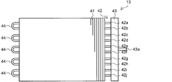
- FIG. 3 is a front view showing the heat exchanger 13 according to Embodiment 1 of the present invention.
- the heat exchanger 13 will be described in detail.
- the heat exchanger 13 has a flat plate shape and includes a plurality of fins 41 and a plurality of tubes 42. Further, the heat exchanger 13 has a header 43 and a bend pipe 44.
- the heat exchanger 13 has a rectangular shape with a wide width in the lateral direction when viewed in the direction of the rotation axis of the boss portion 21.
- the plurality of fins 41 are arranged at intervals in the lateral direction of the heat exchanger 13 and have a flat plate shape.
- the fin 41 has a notch (not shown) into which the tube 42 is inserted by being cut out from one end thereof. Note that the cutout portion is cut out from one end portion by a length equal to or longer than the width of the tube 42 in the long axis direction.
- the plurality of tubes 42 penetrates the plurality of fins 41 in the lateral direction, and the heat medium circulates therein.
- the heat medium flows through at least one flow path (not shown) provided inside the fin 41.
- the tube 42 is, for example, a flat tube, and its cross section has a shape obtained by rounding a rectangle having a high aspect ratio.
- the tube 42 is a hollow metal having high thermal conductivity such as aluminum.
- a plurality of tubes 42 are arranged in a step direction parallel to the gravity direction (longitudinal direction of the fins 41).
- FIG. 3 shows an example in which 10 stages of tubes 42 are arranged.
- the tube 42 is inserted into a notch formed at one end of the fin 41.
- the header 43 is connected to one end portion of the plurality of tubes 42, and causes the refrigerant flowing from the four-way switching valve 12 or the expansion portion 14 through the inflow pipe 43 a to branch into the plurality of tubes 42.
- the bend pipe 44 connects the other ends of the tubes 42 adjacent in the step direction, and has, for example, a U shape.
- each bend pipe 44 connects the other end of the first-stage tube 42a and the other end of the second-stage tube 42b.
- the other end of the tube 42c is connected to the other end of the fourth-stage tube 42d
- the other end of the fifth-stage tube 42e is connected to the other end of the sixth-stage tube 42f
- 7 The other end of the stage tube 42g and the other end of the eighth stage tube 42h are connected, and the other end of the ninth stage tube 42i and the other end of the tenth stage tube 42j are connected.
- the other end parts of the tube 42 have illustrated the structure connected by the bend pipe
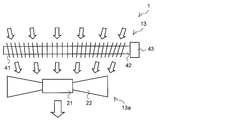
- FIG. 4 is a top view showing the heat exchanger 13 and the blower 13a according to Embodiment 1 of the present invention.
- the arrangement of the fins 41 of the heat exchanger 13 will be described.
- in the heat exchanger 13 at least some of the plurality of fins 41 are inclined toward the boss portion 21 of the blower 13a.
- the air flow in the blower 13 a is parallel to the rotation axis direction of the boss portion 21 in the boss portion 21.
- the air flow in the blower 13 a is inclined toward the boss portion 21 with respect to the rotation axis direction of the boss portion 21 as it goes outward from the boss portion 21.
- the inclination angle of the heat exchanger 13 increases from the fin 41 facing the boss 21 to the outer fin 41 among the plurality of fins 41. That is, one end portion on the blower 13a side in the width direction of the fin 41 is closer to the extension line in the rotation axis direction of the boss portion 21 than the other end portion.
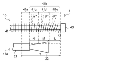
- FIG. 5 is a top view showing the heat exchanger 13 and the blower 13a according to the first embodiment of the present invention.
- the plurality of fins 41 includes a first fin group 41a and a second fin group 41b.
- the first fin group 41a faces the boss portion 21 and is disposed perpendicular to the tube axis direction of the tube 42 in plan view. That is, the arrangement angle formed by the first fin group 41a and the extension line in the rotation axis direction of the boss portion 21 is 0 °.
- the first fin group 41 a faces only the boss portion 21.
- the second fin group 41b is further away from the boss portion 21 than the first fin group 41a and is inclined toward the blower 13a.
- the second fin group 41b has a plurality of fin groups, and the inclination angle is larger on the side away from the boss portion 21 than on the first fin group 41a side.
- the second fin group 41b includes an inner fin group 41c, an intermediate fin group 41d, and an outer fin group 41e.
- the inner fin group 41 c is adjacent to the first fin group 41 a and ranges from the side edge of the boss portion 21 to N (mm) in the width direction of the heat exchanger 13.
- hub part 21 make is (alpha) degrees.
- the middle fin group 41d is adjacent to the inner fin group 41c and ranges from the side edge of the inner fin group 41c to M (mm) in the width direction of the heat exchanger 13.
- the arrangement angle formed by the middle fin group 41d and the extension line of the boss portion 21 in the rotation axis direction is ⁇ °.
- the outer fin group 41e is adjacent to the middle fin group 41d and is in a range of L (mm) from the side edge of the middle fin group 41d to the header 43.
- hub part 21 make is (theta) degrees.
- the plurality of fins 41 in the heat exchanger 13 are arranged symmetrically with respect to the extension line in the rotation axis direction of the boss portion 21 when viewed in the longitudinal direction of the fins 41.
- ⁇ ⁇ ⁇ holds for the arrangement angle. That is, the inclination angle of the heat exchanger 13 increases from the fin 41 facing the boss portion 21 toward the outer fin 41 among the plurality of fins 41. Note that relationships of 0 ° ⁇ ⁇ 10 °, 5 ° ⁇ ⁇ 15 °, and 8 ° ⁇ ⁇ 20 ° hold. Further, assuming that the half value of the stacking width, which is the width from one side of the plurality of fins 41 of the heat exchanger 13 to the other side, is T, the relationship N + M ⁇ T is established.
- the air conditioner 1 As described above, in the air conditioner 1, at least a part of the plurality of fins 41 is inclined toward the boss portion 21 of the blower 13a.
- the flow direction of the air which passes the heat exchanger 13 corresponds with the air blowing direction in the air blower 13a. For this reason, pressure loss is reduced. Thereby, the heat exchange efficiency of the heat exchanger 13 can be improved, and low noise can be realized.
- the inclination angle of the heat exchanger 13 increases from the fin 41 facing the boss portion 21 toward the outer fin 41 among the plurality of fins 41.
- the air flow in the blower 13 a is parallel to the rotation axis direction of the boss portion 21 in the boss portion 21.
- the air flow in the blower 13 a gradually inclines toward the boss portion 21 with respect to the rotation axis direction of the boss portion 21 as it goes outward from the boss portion 21.
- the inclination angle increases from the fin 41 facing the boss portion 21 toward the outer fin 41, so the flow direction of the air passing through the heat exchanger 13 is The air blowing direction in the blower 13a is more consistent. For this reason, the pressure loss is further reduced, the heat exchange efficiency of the heat exchanger 13 is further improved, and noise reduction can be realized.
- the plurality of fins 41 in the heat exchanger 13 are arranged in line symmetry with respect to the extension line in the rotation axis direction of the boss portion 21 when viewed in the longitudinal direction of the fins 41.
- the distribution of the air flowing by the blower 13a becomes uniform in the width direction of the heat exchanger 13. For this reason, the pressure loss is further reduced, the heat exchange efficiency of the heat exchanger 13 is further improved, and noise reduction can be realized.
- the heat exchanger 13 has a rectangular shape with a wide lateral width when viewed in the direction of the rotation axis of the boss portion 21.
- the width of the heat exchanger 13 is wider than that of the blower 13a, the heat exchanger 13 is separated from the blower 13a and the pressure loss increases as the side end of the heat exchanger 13 is approached.
- the plurality of fins 41 are inclined toward the boss portion 21 of the blower 13a.
- the flow direction of the air which passes the heat exchanger 13 corresponds with the air blowing direction in the air blower 13a.
- this Embodiment 1 makes the heat exchanger 13 rectangular shape with a wide width
- the heat exchanger 13 is manufactured by inserting the tube 42 into the notch portion of the fin 41. For this reason, even in the heat exchanger 13 in which the arrangement angles of the plurality of fins 41 are different, it can be easily manufactured.
- FIG. 6 is a top view showing the heat exchanger 113 and the blower 13a in the comparative example.
- the air conditioning apparatus 100 in a comparative example is demonstrated.
- the air flow direction in the heat exchanger 113 is the same throughout the heat exchanger 113.
- the direction of air flow provided by the blower 13a is different in the entire blower 13a.
- the flow direction of the air which passes the heat exchanger 113 does not correspond with the flow direction of the air which the air blower 13a brings. Therefore, pressure loss occurs. Thereby, the heat exchange efficiency of the heat exchanger 113 is inferior, and noise is also generated.
- FIG. 7 is a top view showing the heat exchanger 213 and the blower 13a according to the second embodiment of the present invention.
- the second embodiment is different from the first embodiment in that a plurality of tubes 42 are arranged in parallel to the air blowing direction in the blower 13a.
- portions common to the first embodiment are denoted by the same reference numerals, description thereof is omitted, and differences from the first embodiment will be mainly described.
- a plurality of tubes 42 are arranged in the row direction that is the rotation axis direction of the boss portion 21 in a plan view.
- FIG. 7 shows an example in which the tubes 42 are arranged in two rows in the row direction.
- Each of the plurality of fins 241 in the heat exchanger 213 has an integral shape penetrating all of the plurality of tubes 42.
- the fin 241 has a notch (not shown) cut out from one end by a length equal to or longer than the sum of the widths of the two tubes 42 in the major axis direction.
- the two tubes 42 are inserted in a notch part in the state adjacent to the major axis direction.
- the heat exchange efficiency of the heat exchanger 213 is improved by arranging the tubes 42 in a plurality of rows.
- the plurality of fins 241 have an integral shape, the seam between the fins is eliminated as compared to the case where individual fins are provided for each row of the tubes 42, so that pressure loss is further reduced. Thereby, the heat exchange efficiency of the heat exchanger 213 can be improved, and noise reduction can be realized.
- the plurality of fins 241 may be individually provided for each row of the tubes 42 instead of being integrally formed. Further, the cutout portion may be cut out from both ends by a length equal to or longer than the width of the single tube 42 in the long axis direction. In this case, one tube 42 is inserted into a notch at one end of the fin 241, and the other tube 42 is inserted into a notch at the other end of the fin 241.
- the heat exchanger 13 illustrated what was provided outdoors, it is good also as an indoor heat exchanger provided indoors.
- the fin 41 of the heat exchanger 13 has the 1st fin group 41a which opposes the boss
Landscapes
- Engineering & Computer Science (AREA)
- Mechanical Engineering (AREA)
- General Engineering & Computer Science (AREA)
- Physics & Mathematics (AREA)
- Chemical & Material Sciences (AREA)
- Combustion & Propulsion (AREA)
- Geometry (AREA)
- Thermal Sciences (AREA)
- Other Air-Conditioning Systems (AREA)
- Air Filters, Heat-Exchange Apparatuses, And Housings Of Air-Conditioning Units (AREA)
Abstract
La présente invention concerne un dispositif de climatisation (1) qui est pourvu au moins : d'un boîtier (31) ; d'une pluralité d'ailettes (41) qui sont disposées dans le boîtier (31) et sont espacées les unes des autres dans une direction latérale ; d'un échangeur de chaleur (13) en forme de plaque plane qui a un tube (42) qui pénètre à travers la pluralité d'ailettes (41) et a un milieu de chaleur circulant en son sein ; et d'une soufflante (13a) qui a une partie de bossage (21) et une roue (22) tournant autour de la partie de bossage (21), qui est agencée de manière à faire face à l'échangeur de chaleur (13) dans le boîtier (31), et qui souffle de l'air vers l'échangeur de chaleur (13) par la rotation de la roue (22). Au moins une partie de la pluralité d'ailettes (41) dans l'échangeur de chaleur (13) s'incline vers la partie de bossage (21).
Priority Applications (3)
| Application Number | Priority Date | Filing Date | Title |
|---|---|---|---|
| JP2016568183A JP6316458B2 (ja) | 2015-01-05 | 2015-01-05 | 空気調和装置 |
| PCT/JP2015/050008 WO2016110930A1 (fr) | 2015-01-05 | 2015-01-05 | Dispositif de climatisation |
| CN201520910444.9U CN205156305U (zh) | 2015-01-05 | 2015-11-16 | 空调装置 |
Applications Claiming Priority (1)
| Application Number | Priority Date | Filing Date | Title |
|---|---|---|---|
| PCT/JP2015/050008 WO2016110930A1 (fr) | 2015-01-05 | 2015-01-05 | Dispositif de climatisation |
Publications (1)
| Publication Number | Publication Date |
|---|---|
| WO2016110930A1 true WO2016110930A1 (fr) | 2016-07-14 |
Family
ID=55691991
Family Applications (1)
| Application Number | Title | Priority Date | Filing Date |
|---|---|---|---|
| PCT/JP2015/050008 Ceased WO2016110930A1 (fr) | 2015-01-05 | 2015-01-05 | Dispositif de climatisation |
Country Status (3)
| Country | Link |
|---|---|
| JP (1) | JP6316458B2 (fr) |
| CN (1) | CN205156305U (fr) |
| WO (1) | WO2016110930A1 (fr) |
Cited By (1)
| Publication number | Priority date | Publication date | Assignee | Title |
|---|---|---|---|---|
| WO2018193678A1 (fr) * | 2017-04-20 | 2018-10-25 | 三菱電機株式会社 | Échangeur de chaleur, climatiseur et appareil de fabrication d'un échangeur de chaleur |
Families Citing this family (2)
| Publication number | Priority date | Publication date | Assignee | Title |
|---|---|---|---|---|
| KR20200004216A (ko) * | 2018-07-03 | 2020-01-13 | 주식회사 위니아대우 | 증발기 및 이를 갖는 냉장고 |
| JP7586123B2 (ja) * | 2021-10-28 | 2024-11-19 | 豊田合成株式会社 | 空調用薄型レジスタ |
Citations (6)
| Publication number | Priority date | Publication date | Assignee | Title |
|---|---|---|---|---|
| JPH03129226A (ja) * | 1989-10-13 | 1991-06-03 | Matsushita Electric Ind Co Ltd | 空気調和機の室外ユニット |
| JP2012154493A (ja) * | 2011-01-21 | 2012-08-16 | Daikin Industries Ltd | 熱交換器及び空気調和機 |
| JP2012237538A (ja) * | 2011-05-13 | 2012-12-06 | Daikin Industries Ltd | 熱交換器 |
| JP2013113517A (ja) * | 2011-11-30 | 2013-06-10 | Sanyo Electric Co Ltd | 熱交換器および空気調和装置の室外ユニット |
| JP2013148231A (ja) * | 2012-01-17 | 2013-08-01 | Sharp Corp | 空気調和機の室外機 |
| JP2013213601A (ja) * | 2012-04-02 | 2013-10-17 | Mitsubishi Electric Corp | 熱源機 |
Family Cites Families (1)
| Publication number | Priority date | Publication date | Assignee | Title |
|---|---|---|---|---|
| JP2005308252A (ja) * | 2004-04-19 | 2005-11-04 | Sharp Corp | 熱交換器およびこれを備えた空気調和機の室外ユニット |
-
2015
- 2015-01-05 WO PCT/JP2015/050008 patent/WO2016110930A1/fr not_active Ceased
- 2015-01-05 JP JP2016568183A patent/JP6316458B2/ja not_active Expired - Fee Related
- 2015-11-16 CN CN201520910444.9U patent/CN205156305U/zh not_active Expired - Fee Related
Patent Citations (6)
| Publication number | Priority date | Publication date | Assignee | Title |
|---|---|---|---|---|
| JPH03129226A (ja) * | 1989-10-13 | 1991-06-03 | Matsushita Electric Ind Co Ltd | 空気調和機の室外ユニット |
| JP2012154493A (ja) * | 2011-01-21 | 2012-08-16 | Daikin Industries Ltd | 熱交換器及び空気調和機 |
| JP2012237538A (ja) * | 2011-05-13 | 2012-12-06 | Daikin Industries Ltd | 熱交換器 |
| JP2013113517A (ja) * | 2011-11-30 | 2013-06-10 | Sanyo Electric Co Ltd | 熱交換器および空気調和装置の室外ユニット |
| JP2013148231A (ja) * | 2012-01-17 | 2013-08-01 | Sharp Corp | 空気調和機の室外機 |
| JP2013213601A (ja) * | 2012-04-02 | 2013-10-17 | Mitsubishi Electric Corp | 熱源機 |
Cited By (3)
| Publication number | Priority date | Publication date | Assignee | Title |
|---|---|---|---|---|
| WO2018193678A1 (fr) * | 2017-04-20 | 2018-10-25 | 三菱電機株式会社 | Échangeur de chaleur, climatiseur et appareil de fabrication d'un échangeur de chaleur |
| JPWO2018193678A1 (ja) * | 2017-04-20 | 2019-11-07 | 三菱電機株式会社 | 熱交換器、空気調和機及び熱交換器の製造装置 |
| US11305386B2 (en) | 2017-04-20 | 2022-04-19 | Mitsubishi Electric Corporation | Heat exchanger, air conditioner, and apparatus for manufacturing heat exchanger |
Also Published As
| Publication number | Publication date |
|---|---|
| CN205156305U (zh) | 2016-04-13 |
| JPWO2016110930A1 (ja) | 2017-06-29 |
| JP6316458B2 (ja) | 2018-04-25 |
Similar Documents
| Publication | Publication Date | Title |
|---|---|---|
| CN102639954B (zh) | 热交换器及包括该热交换器的室内机 | |
| JP4749373B2 (ja) | 空気調和機 | |
| US8205470B2 (en) | Indoor unit for air conditioner | |
| US9568221B2 (en) | Indoor unit for air conditioning device | |
| JPWO2013160957A1 (ja) | 熱交換器、室内機及び冷凍サイクル装置 | |
| JP5295321B2 (ja) | 送風機、室外機及び冷凍サイクル装置 | |
| CN107076526B (zh) | 热交换器 | |
| JPWO2013084397A1 (ja) | 空気調和機 | |
| JP6466047B1 (ja) | 熱交換器及び空気調和装置 | |
| CN103097828A (zh) | 空气调节机的室内机 | |
| CN104040263B (zh) | 空气调节机的室外机 | |
| JPWO2016071953A1 (ja) | 空気調和装置の室内機 | |
| TW201825838A (zh) | 除濕裝置 | |
| JP2016200338A (ja) | 空気調和機 | |
| JP6316458B2 (ja) | 空気調和装置 | |
| JP5081881B2 (ja) | 空気調和機 | |
| CN111902683A (zh) | 热交换器及制冷循环装置 | |
| JP6400378B2 (ja) | 空気調和機 | |
| US20250207869A1 (en) | Heat exchanger | |
| EP3524915B1 (fr) | Appareil à cycle de réfrigération | |
| JP2014081150A (ja) | 空気調和機 | |
| JP2019027614A (ja) | 熱交換装置および空気調和機 | |
| JP2006336909A (ja) | 凝縮器及びこれを用いた空気調和機用室内ユニット | |
| JP6545424B1 (ja) | 空気調和機 | |
| JP2006234264A (ja) | フィンチューブ型熱交換器 |
Legal Events
| Date | Code | Title | Description |
|---|---|---|---|
| 121 | Ep: the epo has been informed by wipo that ep was designated in this application |
Ref document number: 15876808 Country of ref document: EP Kind code of ref document: A1 |
|
| ENP | Entry into the national phase |
Ref document number: 2016568183 Country of ref document: JP Kind code of ref document: A |
|
| NENP | Non-entry into the national phase |
Ref country code: DE |
|
| 122 | Ep: pct application non-entry in european phase |
Ref document number: 15876808 Country of ref document: EP Kind code of ref document: A1 |