WO2016110943A1 - Dispositif d'affichage d'image, procédé d'affichage d'image et système d'affichage d'image - Google Patents
Dispositif d'affichage d'image, procédé d'affichage d'image et système d'affichage d'image Download PDFInfo
- Publication number
- WO2016110943A1 WO2016110943A1 PCT/JP2015/050142 JP2015050142W WO2016110943A1 WO 2016110943 A1 WO2016110943 A1 WO 2016110943A1 JP 2015050142 W JP2015050142 W JP 2015050142W WO 2016110943 A1 WO2016110943 A1 WO 2016110943A1
- Authority
- WO
- WIPO (PCT)
- Prior art keywords
- video
- input signal
- display device
- image
- signal
- Prior art date
- Legal status (The legal status is an assumption and is not a legal conclusion. Google has not performed a legal analysis and makes no representation as to the accuracy of the status listed.)
- Ceased
Links
Images






Classifications
-
- G—PHYSICS
- G06—COMPUTING OR CALCULATING; COUNTING
- G06F—ELECTRIC DIGITAL DATA PROCESSING
- G06F16/00—Information retrieval; Database structures therefor; File system structures therefor
- G06F16/50—Information retrieval; Database structures therefor; File system structures therefor of still image data
- G06F16/51—Indexing; Data structures therefor; Storage structures
-
- G—PHYSICS
- G09—EDUCATION; CRYPTOGRAPHY; DISPLAY; ADVERTISING; SEALS
- G09G—ARRANGEMENTS OR CIRCUITS FOR CONTROL OF INDICATING DEVICES USING STATIC MEANS TO PRESENT VARIABLE INFORMATION
- G09G3/00—Control arrangements or circuits, of interest only in connection with visual indicators other than cathode-ray tubes
- G09G3/001—Control arrangements or circuits, of interest only in connection with visual indicators other than cathode-ray tubes using specific devices not provided for in groups G09G3/02 - G09G3/36, e.g. using an intermediate record carrier such as a film slide; Projection systems; Display of non-alphanumerical information, solely or in combination with alphanumerical information, e.g. digital display on projected diapositive as background
-
- G—PHYSICS
- G09—EDUCATION; CRYPTOGRAPHY; DISPLAY; ADVERTISING; SEALS
- G09G—ARRANGEMENTS OR CIRCUITS FOR CONTROL OF INDICATING DEVICES USING STATIC MEANS TO PRESENT VARIABLE INFORMATION
- G09G5/00—Control arrangements or circuits for visual indicators common to cathode-ray tube indicators and other visual indicators
-
- G—PHYSICS
- G09—EDUCATION; CRYPTOGRAPHY; DISPLAY; ADVERTISING; SEALS
- G09G—ARRANGEMENTS OR CIRCUITS FOR CONTROL OF INDICATING DEVICES USING STATIC MEANS TO PRESENT VARIABLE INFORMATION
- G09G5/00—Control arrangements or circuits for visual indicators common to cathode-ray tube indicators and other visual indicators
- G09G5/36—Control arrangements or circuits for visual indicators common to cathode-ray tube indicators and other visual indicators characterised by the display of a graphic pattern, e.g. using an all-points-addressable [APA] memory
- G09G5/363—Graphics controllers
-
- H—ELECTRICITY
- H04—ELECTRIC COMMUNICATION TECHNIQUE
- H04N—PICTORIAL COMMUNICATION, e.g. TELEVISION
- H04N1/00—Scanning, transmission or reproduction of documents or the like, e.g. facsimile transmission; Details thereof
- H04N1/00127—Connection or combination of a still picture apparatus with another apparatus, e.g. for storage, processing or transmission of still picture signals or of information associated with a still picture
- H04N1/00281—Connection or combination of a still picture apparatus with another apparatus, e.g. for storage, processing or transmission of still picture signals or of information associated with a still picture with a telecommunication apparatus, e.g. a switched network of teleprinters for the distribution of text-based information, a selective call terminal
-
- H—ELECTRICITY
- H04—ELECTRIC COMMUNICATION TECHNIQUE
- H04N—PICTORIAL COMMUNICATION, e.g. TELEVISION
- H04N1/00—Scanning, transmission or reproduction of documents or the like, e.g. facsimile transmission; Details thereof
- H04N1/0035—User-machine interface; Control console
- H04N1/00405—Output means
- H04N1/00408—Display of information to the user, e.g. menus
- H04N1/00413—Display of information to the user, e.g. menus using menus, i.e. presenting the user with a plurality of selectable options
- H04N1/00416—Multi-level menus
- H04N1/00419—Arrangements for navigating between pages or parts of the menu
- H04N1/00427—Arrangements for navigating between pages or parts of the menu using a menu list
-
- H—ELECTRICITY
- H04—ELECTRIC COMMUNICATION TECHNIQUE
- H04N—PICTORIAL COMMUNICATION, e.g. TELEVISION
- H04N1/00—Scanning, transmission or reproduction of documents or the like, e.g. facsimile transmission; Details thereof
- H04N1/32—Circuits or arrangements for control or supervision between transmitter and receiver or between image input and image output device, e.g. between a still-image camera and its memory or between a still-image camera and a printer device
- H04N1/327—Initiating, continuing or ending a single-mode communication; Handshaking therefor
- H04N1/32765—Initiating a communication
- H04N1/32771—Initiating a communication in response to a request, e.g. for a particular document
- H04N1/32776—Initiating a communication in response to a request, e.g. for a particular document using an interactive, user-operated device, e.g. a computer terminal, mobile telephone
-
- H—ELECTRICITY
- H04—ELECTRIC COMMUNICATION TECHNIQUE
- H04N—PICTORIAL COMMUNICATION, e.g. TELEVISION
- H04N21/00—Selective content distribution, e.g. interactive television or video on demand [VOD]
- H04N21/20—Servers specifically adapted for the distribution of content, e.g. VOD servers; Operations thereof
- H04N21/23—Processing of content or additional data; Elementary server operations; Server middleware
- H04N21/234—Processing of video elementary streams, e.g. splicing of video streams or manipulating encoded video stream scene graphs
- H04N21/2343—Processing of video elementary streams, e.g. splicing of video streams or manipulating encoded video stream scene graphs involving reformatting operations of video signals for distribution or compliance with end-user requests or end-user device requirements
-
- H—ELECTRICITY
- H04—ELECTRIC COMMUNICATION TECHNIQUE
- H04N—PICTORIAL COMMUNICATION, e.g. TELEVISION
- H04N21/00—Selective content distribution, e.g. interactive television or video on demand [VOD]
- H04N21/20—Servers specifically adapted for the distribution of content, e.g. VOD servers; Operations thereof
- H04N21/25—Management operations performed by the server for facilitating the content distribution or administrating data related to end-users or client devices, e.g. end-user or client device authentication, learning user preferences for recommending movies
- H04N21/258—Client or end-user data management, e.g. managing client capabilities, user preferences or demographics, processing of multiple end-users preferences to derive collaborative data
- H04N21/25808—Management of client data
- H04N21/25825—Management of client data involving client display capabilities, e.g. screen resolution of a mobile phone
-
- H—ELECTRICITY
- H04—ELECTRIC COMMUNICATION TECHNIQUE
- H04N—PICTORIAL COMMUNICATION, e.g. TELEVISION
- H04N21/00—Selective content distribution, e.g. interactive television or video on demand [VOD]
- H04N21/40—Client devices specifically adapted for the reception of or interaction with content, e.g. set-top-box [STB]; Operations thereof
- H04N21/41—Structure of client; Structure of client peripherals
- H04N21/4104—Peripherals receiving signals from specially adapted client devices
- H04N21/4122—Peripherals receiving signals from specially adapted client devices additional display device, e.g. video projector
-
- H—ELECTRICITY
- H04—ELECTRIC COMMUNICATION TECHNIQUE
- H04N—PICTORIAL COMMUNICATION, e.g. TELEVISION
- H04N21/00—Selective content distribution, e.g. interactive television or video on demand [VOD]
- H04N21/40—Client devices specifically adapted for the reception of or interaction with content, e.g. set-top-box [STB]; Operations thereof
- H04N21/47—End-user applications
- H04N21/485—End-user interface for client configuration
- H04N21/4854—End-user interface for client configuration for modifying image parameters, e.g. image brightness, contrast
-
- H—ELECTRICITY
- H04—ELECTRIC COMMUNICATION TECHNIQUE
- H04N—PICTORIAL COMMUNICATION, e.g. TELEVISION
- H04N5/00—Details of television systems
- H04N5/74—Projection arrangements for image reproduction, e.g. using eidophor
-
- H—ELECTRICITY
- H04—ELECTRIC COMMUNICATION TECHNIQUE
- H04N—PICTORIAL COMMUNICATION, e.g. TELEVISION
- H04N9/00—Details of colour television systems
- H04N9/12—Picture reproducers
- H04N9/31—Projection devices for colour picture display, e.g. using electronic spatial light modulators [ESLM]
- H04N9/3179—Video signal processing therefor
- H04N9/3182—Colour adjustment, e.g. white balance, shading or gamut
-
- H—ELECTRICITY
- H04—ELECTRIC COMMUNICATION TECHNIQUE
- H04N—PICTORIAL COMMUNICATION, e.g. TELEVISION
- H04N9/00—Details of colour television systems
- H04N9/12—Picture reproducers
- H04N9/31—Projection devices for colour picture display, e.g. using electronic spatial light modulators [ESLM]
- H04N9/3179—Video signal processing therefor
- H04N9/3185—Geometric adjustment, e.g. keystone or convergence
-
- H—ELECTRICITY
- H04—ELECTRIC COMMUNICATION TECHNIQUE
- H04N—PICTORIAL COMMUNICATION, e.g. TELEVISION
- H04N9/00—Details of colour television systems
- H04N9/12—Picture reproducers
- H04N9/31—Projection devices for colour picture display, e.g. using electronic spatial light modulators [ESLM]
- H04N9/3179—Video signal processing therefor
- H04N9/3188—Scale or resolution adjustment
-
- H—ELECTRICITY
- H04—ELECTRIC COMMUNICATION TECHNIQUE
- H04N—PICTORIAL COMMUNICATION, e.g. TELEVISION
- H04N9/00—Details of colour television systems
- H04N9/12—Picture reproducers
- H04N9/31—Projection devices for colour picture display, e.g. using electronic spatial light modulators [ESLM]
- H04N9/3191—Testing thereof
- H04N9/3194—Testing thereof including sensor feedback
-
- G—PHYSICS
- G09—EDUCATION; CRYPTOGRAPHY; DISPLAY; ADVERTISING; SEALS
- G09G—ARRANGEMENTS OR CIRCUITS FOR CONTROL OF INDICATING DEVICES USING STATIC MEANS TO PRESENT VARIABLE INFORMATION
- G09G2320/00—Control of display operating conditions
- G09G2320/06—Adjustment of display parameters
- G09G2320/0626—Adjustment of display parameters for control of overall brightness
-
- G—PHYSICS
- G09—EDUCATION; CRYPTOGRAPHY; DISPLAY; ADVERTISING; SEALS
- G09G—ARRANGEMENTS OR CIRCUITS FOR CONTROL OF INDICATING DEVICES USING STATIC MEANS TO PRESENT VARIABLE INFORMATION
- G09G2320/00—Control of display operating conditions
- G09G2320/06—Adjustment of display parameters
- G09G2320/066—Adjustment of display parameters for control of contrast
-
- G—PHYSICS
- G09—EDUCATION; CRYPTOGRAPHY; DISPLAY; ADVERTISING; SEALS
- G09G—ARRANGEMENTS OR CIRCUITS FOR CONTROL OF INDICATING DEVICES USING STATIC MEANS TO PRESENT VARIABLE INFORMATION
- G09G2320/00—Control of display operating conditions
- G09G2320/10—Special adaptations of display systems for operation with variable images
- G09G2320/106—Determination of movement vectors or equivalent parameters within the image
-
- G—PHYSICS
- G09—EDUCATION; CRYPTOGRAPHY; DISPLAY; ADVERTISING; SEALS
- G09G—ARRANGEMENTS OR CIRCUITS FOR CONTROL OF INDICATING DEVICES USING STATIC MEANS TO PRESENT VARIABLE INFORMATION
- G09G2340/00—Aspects of display data processing
- G09G2340/02—Handling of images in compressed format, e.g. JPEG, MPEG
-
- G—PHYSICS
- G09—EDUCATION; CRYPTOGRAPHY; DISPLAY; ADVERTISING; SEALS
- G09G—ARRANGEMENTS OR CIRCUITS FOR CONTROL OF INDICATING DEVICES USING STATIC MEANS TO PRESENT VARIABLE INFORMATION
- G09G2340/00—Aspects of display data processing
- G09G2340/04—Changes in size, position or resolution of an image
- G09G2340/0442—Handling or displaying different aspect ratios, or changing the aspect ratio
-
- G—PHYSICS
- G09—EDUCATION; CRYPTOGRAPHY; DISPLAY; ADVERTISING; SEALS
- G09G—ARRANGEMENTS OR CIRCUITS FOR CONTROL OF INDICATING DEVICES USING STATIC MEANS TO PRESENT VARIABLE INFORMATION
- G09G2370/00—Aspects of data communication
- G09G2370/04—Exchange of auxiliary data, i.e. other than image data, between monitor and graphics controller
-
- G—PHYSICS
- G09—EDUCATION; CRYPTOGRAPHY; DISPLAY; ADVERTISING; SEALS
- G09G—ARRANGEMENTS OR CIRCUITS FOR CONTROL OF INDICATING DEVICES USING STATIC MEANS TO PRESENT VARIABLE INFORMATION
- G09G2370/00—Aspects of data communication
- G09G2370/04—Exchange of auxiliary data, i.e. other than image data, between monitor and graphics controller
- G09G2370/042—Exchange of auxiliary data, i.e. other than image data, between monitor and graphics controller for monitor identification
-
- G—PHYSICS
- G09—EDUCATION; CRYPTOGRAPHY; DISPLAY; ADVERTISING; SEALS
- G09G—ARRANGEMENTS OR CIRCUITS FOR CONTROL OF INDICATING DEVICES USING STATIC MEANS TO PRESENT VARIABLE INFORMATION
- G09G2370/00—Aspects of data communication
- G09G2370/12—Use of DVI or HDMI protocol in interfaces along the display data pipeline
Definitions
- the present invention relates to a video display device that displays video on a monitor, a video display method, and a video display system, and more particularly to image correction of a display image.
- Patent Document 1 states that “When the correction control unit detects that the projector and the computer are connected, the connection information and correction parameters are read out via the input / output control unit. In response to the request, the main control circuit appropriately operates the interface unit at an appropriate timing on the projector side, and correction parameters such as display information and shape correction data in the memory are displayed. Is output to the computer side, where the correction control unit captures connection information and correction parameters via the interface unit ”(summary extract).
- Patent Document 2 states that “in the projector device, the zoom position and the installation angle of the projector to be projected are detected and sent to the image output device, and the output device side corrects the distortion of the image according to the installation angle, and “A correction of trapezoidal distortion and the like” (summary excerpt) is disclosed.
- Patent Document 1 and Patent Document 2 a projector and a computer are connected, and image processing suitable for the projector is performed on video data stored in the computer.
- image processing is complicated and has a high load, it is necessary to mount an image processing circuit for executing the image processing function in the video display device, which increases the manufacturing cost of the video display device. There is still room for further innovations in this regard.
- the present invention has been made in view of the above problems, and an object of the present invention is to easily generate a high-quality image with a cheaper video display device.
- the present invention connects an image display device and an image processing device via a network, and generates instruction information related to image processing to be performed on the image input signal to the image display device.
- a generation unit a video signal transmission unit that transmits the instruction information to a video processing device connected via the network; and the image processing device that performs image processing based on the instruction information with respect to the video input signal.
- a corrected signal receiving unit that receives the corrected video input signal generated by performing the correction, a display signal output unit that outputs a video output signal based on the corrected video input signal to a display object, And an image processing unit that performs image processing based on the instruction information for the video input signal.
- Configuration diagram showing an example of a video display system according to the present embodiment It is a figure which shows the hardware constitutions of a video display apparatus and a video processing apparatus, Comprising: (a) shows a video display apparatus, (b) shows a video processing apparatus.
- the block diagram which shows the function structure of the video display apparatus 10 which concerns on 1st embodiment.
- Block diagram showing functional configuration of video processing device It is an additional image showing a processing result in the video processing apparatus, where (a) is an image at the time of successful authentication, (b) an image at the time of an authentication error, (c) is an image of a security error, and (d) is an image of a content error. Indicates.
- FIGS. 2A and 2B are diagrams illustrating an example of a setting screen for image processing in a video processing apparatus, where FIG. 3A is a setting screen in an initial state, FIG. A setting screen when image processing for environment adaptation is invalid, and (d) shows a setting screen for light and dark environment adaptation.
- Sequence diagram showing operation of video display processing system The block diagram which shows an example of the video display apparatus which concerns on 2nd embodiment.
- Detailed configuration diagram of the decoding unit in the second embodiment The block diagram which shows the structure of the other example of the decoding part in 2nd embodiment.
- the block diagram which shows an example of the video display apparatus of 4th embodiment The block diagram which shows an example of the video display system which concerns on 5th embodiment
- the block diagram which shows an example of the video display system which concerns on 6th embodiment The block diagram which shows an example of the video display apparatus concerning 6th embodiment
- FIG. 1 is a configuration diagram illustrating an example of a video display system according to the present embodiment.
- a video display system 1 shown in FIG. 1 includes a video display device 10 installed in a place where a user is present, for example, a general home 2, and a video processing device 20 installed on the service provider 3 side, in a public line such as the Internet. It is configured to be connected via a network (hereinafter referred to as a network) 4.
- the video display device 10 is a device for displaying video to the user, and includes, for example, a projector, a television display device, a mobile phone, a tablet, a digital camera, a portable game machine, an in-vehicle monitor device, and a recorder.
- the video processing device 20 is a device that performs image processing for improving the image quality of the video displayed by the video display device 10, and includes an image processing server device, a cloud device, and a computer connected to the network 4.
- the video display device 10 is connected to a video signal supply source 11, for example, a computer 11 a or a television 11 b (including a connection terminal for a cable television or a satellite broadcast television reception signal). And it displays on the display object 12 which displays the video signal after the correction process mentioned later.
- a video signal supply source 11 for example, a computer 11 a or a television 11 b (including a connection terminal for a cable television or a satellite broadcast television reception signal).
- the display object 12 is the monitor 12a
- the monitor 12a is electrically connected to the video display device 10.
- the display object 12 may be a screen 12b on which projection light generated based on the video output signal is projected.
- the video display device 10 confirms the operation buttons (corresponding to the input operation unit) for inputting information relating to image processing to be performed on the video input signal and various setting information, and the state of the video display device 10.
- An input / output device 13 including a display panel and a sensor device 14 for detecting information necessary for determining the contents of image processing for a video input signal.
- This sensor device 14 is an installation state of the image display device 10, for example, an inclination angle detection sensor that detects an inclination angle with respect to a horizontal plane, or an ambient light environment that detects the surrounding environment of the image display device 10 or the display object 12a, for example, an illuminance sensor. is there.
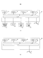
- FIG. 2 is a diagram illustrating the hardware configuration of the video display device and the video processing device, where (a) shows the video display device and (b) shows the video processing device.
- the video display device 10 includes a CPU (Central Processing Unit) 11, RAM (Random Access Memory) 12, ROM (Read Only Memory) 13, HDD (Hard Disk Drive) 14, and I. / F15 and bus 18 are included.
- the CPU 11, RAM 12, ROM 13, HDD 14, and I / F 15 are connected to each other via a bus 18.
- the video display device 10 is connected to the video signal providing source 11, the monitor 12 a, the input / output device 13, the sensor device 14, and the network 4 via the I / F 15.
- the video processing apparatus 20 includes a CPU 21, a RAM 22, a ROM 23, an HDD 24, an I / F 25, and a bus 28 as shown in FIG.
- the CPU 21, RAM 22, ROM 23, HDD 24, and I / F 25 are connected via the bus 28.
- the video processing device 20 is connected to the network 4 via the I / F 15.
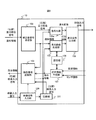
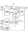
- FIG. 3 is a block diagram showing a functional configuration of the video display apparatus 10 according to the first embodiment.
- the video display device 10 includes a video signal input unit 100, a compression unit 101, a video signal transmission unit 102, a corrected signal reception unit 103, a decoding unit 104, a display image generation unit 105, a display signal output unit 106, and an instruction information generation unit. 107 and a storage unit 108.
- the video signal input unit 100 receives an input of an uncompressed video input signal (also referred to as a pre-correction video signal) from the video signal providing source 11. More specifically, it is a block that accepts an input of a video input signal output from the video signal providing source 11 and transfers it to the compression unit 101.
- Examples of the video input signal include a compression-encoded video signal (HEVC, H.264, MPEG2, Motorino JPEG, etc.) and an uncompressed video signal (RGB format, YUV format, etc.).
- the compression unit 101 may not be provided. Even if the compression unit 101 is provided, the compressed video input signal may be directly transferred from the video signal input unit 100 to the video signal transmission unit 102 (illustrated by a dotted line in FIG. 3).
- Examples of interfaces that connect the video signal input unit 100 and the video signal providing source 11 include HDMI (registered trademark), USB, IEEE 1394, DVI, Ethernet (registered trademark), and the like.
- the compression unit 101 is a module that receives an input of a video input signal from the video signal input unit 100 and compresses and encodes the video input signal into a data format applied to data transmission / reception on the network 4. For example, when the video input signal is an uncompressed video signal, a process of converting into a compressed encoded video signal is performed.
- the video signal transmission unit 102 inputs the video input signal supplied from the video signal input unit 100, instruction information supplied from the instruction information generation unit 107, and notification information supplied from the corrected signal reception unit 103. Accept. Then, the video signal transmission unit 102 determines whether or not the video input signal and the instruction information can be output based on the notification information, and outputs the video input signal and the instruction information to the network 4 when it is determined that the output is possible.
- Examples of interfaces for connecting the video signal transmitting unit 102 and the corrected signal receiving unit 103 to the network 4 include HDMI, USB, DVI, IEEE 1394, Ethernet, and the like.
- the corrected signal receiving unit 103 is a video input signal after image processing (hereinafter referred to as “corrected video signal”) from the video generated by the video processing device 20 performing image processing based on the instruction signal on the video input signal. And notification information.
- the notification information is information supplied from the video processing device 20 and includes at least one of error information detected when image processing is performed and an authentication result between the video display device 10 and the video processing device 20. Information.
- the post-correction signal receiving unit 103 outputs the received post-correction video signal to the decoding unit 104, and outputs the notification information to the display image generation unit 105 and the video signal transmission unit 102.
- the decoding unit 104 is a block that performs a decoding process on the corrected video signal supplied from the corrected signal receiving unit 103 to generate and output a decoded image.
- the display image generation unit 105 receives input of the notification information supplied from the corrected signal reception unit 103 and the instruction information supplied from the instruction information generation unit 107, and serves as at least one of notification information and / or instruction information. This is a block for generating and outputting an additional image based thereon.
- the display signal output unit 106 is a block that receives an input of a decoded image and an additional image, performs a synthesis process, and then outputs a video output signal to the monitor 11a. When an additional image when viewing is not permitted is input, only the additional image is output as a video output signal.
- the instruction information generation unit 107 receives input of setting information supplied from the input / output device 13 and sensor information supplied from the sensor device 14, and specifies instruction information that defines the content of image processing executed by the video processing device 20. Generate and output.
- the instruction information may include setting information and sensor information.
- the instruction information generation unit 107 may extract and output only predetermined information from the setting information and sensor information according to the output destination of the instruction information.
- the setting information and instruction information may include the display position, display size, transmission level, and the like of the additional image.
- the instruction information input to the display image generation unit 105 includes a display position, a display size, and a transmission level
- the display image generation unit 105 generates an additional image based on the instruction information.
- the storage unit 108 stores various information.
- the storage unit 108 may temporarily hold setting information, sensor information, and instruction information, or may store initial values of the setting information, sensor information, and instruction information in the storage unit 108 in advance.
- the instruction information generation unit 107 may generate instruction information using the setting information and sensor information stored in the storage unit 108.
- the stored instruction information may be read and output.
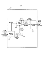
- FIG. 4 is a block diagram illustrating a functional configuration of the video processing device 20.
- the video processing device 20 includes a video signal receiving unit 201, a decoding unit 202, an image processing unit 203, a compression unit 204, and a corrected signal transmission unit 205.
- the video signal receiving unit 201 receives a compressed video input signal and instruction information from the video display device 10 via the network 4.
- the video signal receiving unit 201 outputs the compressed video input signal to the decoding unit 202 and outputs instruction information to the image processing unit 203.
- the decoding unit 202 executes a decoding process on the compressed video input signal and outputs the decoded video input signal to the image processing unit 203.
- the image processing unit 203 performs image processing based on the instruction information on the decoded video input signal acquired from the decoding unit 203. Details of this processing will be described later.
- the image processing unit 203 outputs the video signal after image processing (hereinafter referred to as “corrected signal”) to the compression unit 204.
- the image processing unit 203 generates notification information indicating an error that has occurred or was found during image processing, and outputs the notification information to the post-correction signal transmission unit 205.
- the compression unit 204 compresses the corrected signal in a compression format suitable for data transmission through the network 4 and outputs the compressed signal to the corrected signal transmission unit 205.
- the post-correction signal transmission unit 205 transmits the compressed post-correction signal and / or notification information to the video display device 10 via the network 4.
- FIG. 5A and 5B are additional images showing the processing results in the video processing apparatus 10, where FIG. 5A is an image when authentication is successful, FIG. 5B is an image when authentication error occurs, FIG. 5C is a security error image, and FIG. Indicates an image of content error.
- the additional image 500 is an example of the additional image that is output when the authentication process is completed between the video display device 10 and the video processing device 20 and the connection is permitted (see FIG. 5A).
- the additional image 501 is an example of an additional image in a case where connection is not permitted as a result of the authentication processing between the video display device 10 and the video processing device 20 (see FIG. 5B). In this example, when the video display device 10 is not registered in the video processing device 20, the additional image 501 is output.
- the additional image 502 is an example of the additional image when the video processing device 20 determines that the video input signal supplied from the video display device 10 cannot be displayed for security reasons (see FIG. 5C). .
- the additional image 503 is an example of the additional image when it is determined in the video processing device 20 that the video input signal supplied from the video display device 10 violates the age limit (see (d) of FIG. 5).
- As a method for determining whether or not the age restriction is violated there is a verification of the age restriction level described in the instruction information and the age restriction information included in the video input signal.
- the age restriction information is information indicating the age range and lower limit for which viewing is permitted.
- the additional images 502 and 503 correspond to images displayed when viewing is not permitted.
- the additional image may be temporarily stored in the storage unit 108 or may be stored in advance in the storage unit 108 as an initial value. Further, the additional image may be downloaded from the video processing device 20 via the network 4 and the corrected signal receiving unit 103 and stored in the storage unit 108. Further, the additional image stored in the storage unit 108 may be read and output.
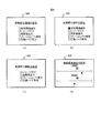
- FIG. 6 shows an example of a setting screen for image processing content as another example of the additional image.
- FIG. 6 is a diagram illustrating an example of a setting screen for image processing in the video processing apparatus 10, where (a) is a setting screen in an initial state, (b) is a setting screen after the user has set image processing content, c) shows a setting screen when image processing for light and dark environment adaptation is disabled, and (d) shows a setting screen for light and dark environment adaptation.
- the additional image 600 is an example of an image processing setting screen that is permitted to be processed by the video processing device 20 (see FIG. 6A).
- the additional image 601 is an example of an additional image when the user has enabled image processing for adaptation to the light and dark environment via the input / output device 13 on the setting screen displayed on the additional image 601 (FIG. 6). (See (b)).
- the additional image 602 is, for example, a contract for this function, that is, between the user of the video display device 10 and the service providing company 3 of the video processing device 20 when the image processing of the image processing device 20 is disabled in the light and dark environment adaptation.
- 2 is an example of an additional image when a contract for executing image processing for light / dark environment adaptation processing is not performed (see FIG. 6C).
- the additional image 603 is an example of an additional image showing a detailed parameter setting screen for image processing adapted to light and dark environments (see FIG. 6D).
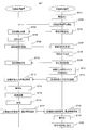
- FIG. 7 is a sequence diagram showing the operation of the video display processing system in the first embodiment. At the start of the following processing, it is assumed that the video processing device 20 is powered on and is waiting for access from the video display device 10.
- the video display device 10 is turned on (S701), and connected to the video processing device 20 via the network 4 (S702).
- the video display apparatus 10 transmits contract information to the video processing apparatus 20 via the network 4 (S703).
- This contract information indicates an agreement regarding the type and content of image processing exchanged between the user of the video display device 10 and the service provider 3 (see FIG. 1) of the video processing device 20.
- Information for the processing device 20 to individually identify the video display device 10 is also included.
- the contract information may be transmitted by reading the contract information stored in the storage unit 108 by the video signal transmitting unit 102 (not shown).
- the video processing device 20 receives the contract information (S704), and authenticates whether the video display device 10 is permitted to connect based on the contract information (S705).
- the video processing device 20 transmits the authentication result as notification information to the video display device 10 via the network 4 (S706).
- the video signal receiving unit 201 may receive the contract information.
- the video processing device 20 may include an authentication processing unit (not shown), and the result may be output to the corrected signal transmission unit 205.
- the display image generation unit 105 of the video display device 10 Upon receiving notification information indicating connection permission from the video processing device 20 (S707), the display image generation unit 105 of the video display device 10 displays a display indicating the completion of authentication on the monitor 12a (S708). As an example of display on the monitor 12a, there are an additional image 500 (see FIG. 5A) and an additional image 501 (see FIG. 5A).
- the video processing apparatus 20 may further output information indicating a list of contracted image processing as the notification information.
- the video display device 10 may display a list of image processes that can be processed by the video processing device 20 on the monitor 12a as a setting screen based on the notification information. As an example of the setting screen, there is an additional image 600 (see FIG. 6A).
- a list of contracted image processing may be stored in the storage unit 108 and the setting screen may be generated.
- connection between the video display device 10 and the video processing device 20 can be completed by the above procedure.
- the video signal transmission unit 102 of the video display device 10 performs video processing on the instruction information defining the content of the image processing (including the type of image correction and the target value for the correction) via the network 4. Transmission to the apparatus 20 (S709), and the video signal receiving unit 201 of the video processing apparatus 20 receives it (S710).
- the instruction information is generated by the instruction information generation unit 107 based on at least one of setting information supplied from the input / output device 13 and sensor information supplied from the sensor device 14.
- the instruction information generation unit 107 may generate instruction information using storage information stored in advance in the storage unit 108.
- the stored information there are setting information and instruction information set last time, setting information preset at initialization, instruction information, and sensor information.
- setting information there are a corrected video signal format, image processing type and mode, correction level information and detailed correction parameters in predetermined image processing, an age restriction level, and the like.
- Examples of the video signal format after the correction include resolution, frame rate, and compression encoding format.
- the image processing mode there are a light / dark environment adaptive mode, a cinema mode, a sports mode, a still image mode, and a character display mode in which image processing such as contrast correction is performed according to the brightness around the monitor 12a and the video display device 10. is there.
- Examples of the types of image processing include contrast correction, sharpness, edge enhancement, noise removal, gamma correction, color temperature correction, gradation expansion correction, distortion correction, resolution conversion, frame rate conversion, and zoom processing.
- correction level information and detailed correction parameters in predetermined image processing there is a setting of correction levels for a dark part and a bright part in a light / dark environment adaptation mode (see FIG.
- the video signal format, the image processing mode, and the type of image processing can be set by the user on the setting screen (see (a), (b), and (c) of FIG. 6) displayed on the monitor 12a of the video display device 10. This can be done by operating the input / output device 13.
- the video processing device 20 compares the age restriction information of the video input signal for image processing with the age restriction level supplied from the video display device 10, and displays the video as notification information whether or not it is within the age restriction range. Transmit to device 10. Based on the notification information, the video display device 10 displays on the monitor 12a only when it is within the age limit range indicated by the age limit level, thereby determining whether or not the video display device 10 is within the age limit range. It is possible to display according to the age restriction level without performing the above. When the video signal is not within the age limit range, notification information indicating that fact is transmitted from the video processing device 20 to the video display device 10, and an additional image indicating that fact (see FIG. 5D) is displayed on the monitor 12a. Is displayed.
- the age restriction information acquisition method there is a method of extracting age restriction information stored in a user data area of a video input signal for image processing.
- the video processing apparatus 20 has library information including information on age limit ranges of various video input signals, and collates the video input signal supplied from the video display apparatus 10 with the library information.
- sensor information there is an illuminance level around the monitor 12a and the video display device 10.
- the video input signal is input from the video signal providing source 11 to the video signal input unit 10 of the video display device 10 (S711). If necessary, the compression unit 101 performs compression processing according to a predetermined encoding method A on the video input signal input from the video signal input unit (S711). Then, the video signal transmission unit 102 transmits the compressed video input signal to the video processing device 20 (S712).
- the video signal receiving unit 201 of the video processing device 20 receives the video input signal supplied from the video display device 10 via the network 4 (S713).
- the decoding unit 202 performs a decoding process for the encoding scheme A, and generates a first decoded image (S714).
- the image processing unit 203 performs image processing such as light and dark environment adaptation processing and format conversion on the first decoded image according to the instruction information, and generates a corrected second decoded image (S715).
- image processing such as light and dark environment adaptation processing and format conversion on the first decoded image according to the instruction information, and generates a corrected second decoded image (S715).
- the format conversion there is a compression encoding process in the same format as the video input signal supplied from the video display device 10 or a compression encoding format described in the instruction information, and a bit rate. Further, processing such as resolution conversion and frame rate conversion may be performed before the compression encoding processing.
- the compression unit 204 performs compression encoding processing on the second decoded image after correction in the same format as the first video stream, generates a second video stream, and outputs the second video stream as a corrected video signal (S716).
- the image processing unit 204 may further output notification information.
- the notification information there is error information for a video input signal detected by the video processing device 20.
- the video input signal is a video stream compressed by a predetermined encoding method, and information such as a grammatical error or data corruption detected by the video processing device 20 during the decoding process, There is information indicating that the video stream encoding method is not supported by the video processing device 20.
- the corrected signal transmission unit 205 of the video processing device 20 transmits the second video stream and / or the notification information to the video display device 10 (S717), and the corrected signal reception unit 103 of the video display device 10 receives it. (S718).
- the decoding unit 104 performs second decoding processing on the corrected video signal supplied from the video processing device 20 to generate a second decoded image (S719), and the display signal output unit 106 outputs the video output signal. To the monitor 12a (or the display object 12) (S720).
- the video display device 10 may output a display regarding the occurrence of an error to the monitor 12a based on the error information.
- the video processing device 20 connected via the network executes image processing for improving the image quality of the image displayed by the video display device 10. Therefore, it is not necessary to mount a complicated image processing circuit in the video display device 10, and the manufacturing cost of the video processing device 10 can be reduced.
- image processing is performed by the video processing device 20, so power consumption that can be used at the installation location of the video display device 10. Can be suppressed.
- the video processing device 20 can connect a plurality of video display devices 10 via a network and perform image processing in response to a request from each video display device 10. Therefore, when updating the image processing function, it is only necessary to update the function of the video processing device 20, so that there is no inconvenience that the function update of each video processing device 10 varies.
- the video processing device 20 is configured by a device different from the video signal providing source 11, the video input signal can be corrected regardless of the type of the video signal providing source. Furthermore, when the display conditions of each video display device 10 are different, such as the brightness of the surroundings, even if the video display device 10 is the same, the image quality can be corrected according to the display environment at that time.
- the video display device 10 shown in the second embodiment is obtained by changing the decoding unit of the video display device 10 in the video display device 10 and the video display system 1 shown in the first embodiment.
- the same symbols are attached to the same members, and the repeated description thereof is omitted.
- FIG. 8 is a configuration diagram illustrating an example of the video display device 10 according to the second embodiment. Hereinafter, the configuration of the video display device 10 will be described.
- the decoding unit 104a is a block that receives the input of the corrected video input signal supplied from the corrected signal receiving unit 103 and the video input signal supplied from the video signal input unit 100, and outputs a decoded image. .
- three modes of the decoding unit 104a that is, 104a, 104b, and 104c will be exemplified.
- the corrected video input signal is a differential video signal having difference image information between the first decoded image before correction generated by the video processing device 20 and the second decoded image after correction.
- the video input signal supplied from the video signal input unit 100 is the same as the video input signal supplied to the video signal transmission unit 102.
- the video input signal supplied from the compression unit 101 is also the same as the video input signal supplied to the video signal transmission unit 102.
- FIG. 9 is an example of a detailed configuration diagram of the decoding unit 104a in the present embodiment.
- the decoding unit 104a includes a first decoding unit 104a1, a second decoding unit 104a2, and a decoded image generation unit 104a3.
- the first decoding unit 104a1 is a block that receives the differential video signal supplied from the corrected signal receiving unit 103, generates a differential decoded image by decoding processing on the differential video signal, and outputs the differential decoded image.
- difference decoded image difference decoded image obtained by taking a difference between pixel values of the first decoded image and the second decoded image generated by the video processing device 20.
- One decoded image One decoded image).
- the second decoding unit 104a2 is a block that receives the video input signal supplied from the video signal input unit 100 or the compression unit 101, generates a first decoded image by decoding processing on the video input signal, and outputs the first decoded image.
- the block is output as a decoded image.
- the data amount of the corrected video input signal input by the video display device 10 is reduced, and this system can be applied even when the transmission band of the network 4 is low.
- more video display devices 10 can be connected to the network 4.
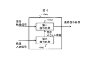
- FIG. 10 is a diagram showing a configuration of another example of the decoding unit in the present embodiment.
- the video processing device 20 performs compression encoding processing on the second decoded image using motion vector information obtained by decoding processing on the input video input signal, and removes motion vector information from the obtained compression encoded video signal.
- the difference video signal is a signal obtained by removing motion vector information from the corrected video input signal generated by the compression encoding process for the second decoded image generated by the video processing device 20.
- the decoding unit 104b shown in FIG. 10 includes a first decoding unit 104b1 and a second decoding unit 104b2.
- the second decoding unit 104b2 is a block that receives the video input signal supplied from the video signal input unit 100, extracts the motion vector information by a decoding process on the video input signal, and outputs the motion vector information.
- the first decoding unit 104b1 receives the difference video signal supplied from the corrected signal reception unit 103, and performs a decoding process on the difference video signal using the motion vector information supplied from the second decoding unit 104b2. This is a block for generating and outputting a final decoded image.
- the data amount of the corrected video input signal input by the video display device 10 is reduced, and this system can be applied even when the transmission band of the network 4 is low. In addition, more video display devices 10 can be connected to the network 4.
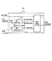
- FIG. 11 is a diagram showing a configuration of another example of the decoding unit in the present embodiment.
- the decoding unit 104c in FIG. 11 can handle a plurality of difference video signals.
- the decoding unit 104c includes a first decoding unit 104c1, a second decoding unit 104c2, and a third decoding unit 104c3.
- the instruction information generation unit 107 further supplies the instruction information to the decoding unit 104, and the decoding unit 104 acquires the instruction information.
- the instruction information includes difference video signal format information indicating the type of the difference video signal.
- instruction information is input to each of the first decoding unit 104c1, the second decoding unit 104c2, and the decoded image generation unit 104c3.
- the first decoding unit 104 c 1, the second decoding unit 104 c 2, and the third decoding unit 104 c 3 perform the processing method described in FIG. 9. To generate and output a decoded image.
- the first decoding unit 104c1 and the second decoding unit 104c2 When the difference video signal format information indicates the format of the difference video information shown in FIG. 10, the first decoding unit 104c1 and the second decoding unit 104c2 generate a final decoded image by the processing method described in FIG. And output to the decoded image generation unit 102c3.
- the decoded image generation unit 102c3 outputs the final decoded image to the display signal output unit 105 as it is.
- the third embodiment has a configuration in which the video display device 10 is a projector.
- the display signal output unit 106 of the video display device 10 is used as a projector. It is materialized to be applied.
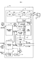
- FIG. 12 is a configuration diagram showing an example of a projector 10a according to the third embodiment. Hereinafter, the configuration of the projector 10 will be described.
- the display signal output unit 106 includes a video generation unit 900, a timing control unit 901, a light source 902, a panel 903, and a lens 904.
- the video generation unit 900 receives the decoded image supplied from the decoding unit 104 and the additional image supplied from the display image generation unit 106, generates a display image by combining the decoded image and the additional image, and outputs the display image. It is a block.
- the synthesis process there is a process of superimposing an additional image on a decoded image.
- a transmission process such as an ⁇ blend process may be added.
- only the decoded image or only the additional image may be output as the display image.
- the timing control unit 901 is a block that receives a display image input and generates a display control signal based on a horizontal / vertical synchronization signal of a display screen constituting the display image.
- the panel 903 is a block that accepts input of a light beam output from the light source 902 and a display control signal output from the timing control unit 901, and adjusts the gradation of the light beam for each pixel to create a projection image.
- the lens 904 is a block that adjusts the focus of the light beam that has passed through the panel 903 and projects it onto the screen 12b.
- the image projected on the screen 12b is a high-quality image after image processing is performed by the image processing device 20.
- information on the installation state of the projector 10 with respect to the screen installation surface is an example of setting information and sensor information.
- image processing include keystone correction, blur reduction, and contrast improvement.
- a projector is projected on a screen or the like that is vertically attached to an installation surface such as a desk, wall, or ceiling.
- an installation surface such as a desk, wall, or ceiling.
- a clear image can be projected on the screen.
- the installation surface of the projector and the installation surface of the screen cannot be mounted vertically.
- the image is distorted and is not projected in a rectangular range.
- a technique for adjusting this distortion to a rectangle is keystone correction. According to this correction, the image input signal is converted into a rectangle by performing a geometric conversion operation such as reduction or enlargement according to the installation state of the projector.
- the keystone correction process can be executed by the video processing device 20 outside the projector 10a, and the cost reduction of the projector and the enhancement of the performance of the functions are realized. it can.
- the video display device 10 shown in the fourth embodiment uses a computer 11a as the video signal providing source 11 in the video display device 10 and the video display system 1 shown in the first embodiment, and the video signal input unit 100a of the video display device 10. Is an embodiment that receives input of a video signal and a setting signal from the computer 11a.
- FIG. 13 is a configuration diagram illustrating an example of the video display device 10 according to the fourth embodiment. In FIG. 13, the compression unit 101 is not shown.
- the computer 11a is connected to the video display device 10 (see FIG. 1), and outputs a video input signal and a control signal to be subjected to image processing.
- the video signal input unit 100a receives input of a video input signal and a control signal. Note that the input / output device 13 for inputting the setting information in FIG. 1 by inputting the setting information from the computer 11a is not necessary in this embodiment.
- setting information can be supplied and controlled from the computer 11a that supplies the video input signal to the video display device 10 and the video processing device 20.
- the video display system shown in the fifth embodiment is the same as the video display system shown in the fourth embodiment except that the transmission method between the video display device 10 and the video processing device 20 is changed, and the video display device 10 and video from the mobile terminal 30 are changed.
- the configuration is such that setting information can be supplied and controlled to the processing device 20.
- FIG. 14 is a configuration diagram showing an example of a video display system 1a according to the fifth embodiment.
- the mobile terminal 30 is a block that transmits and receives various types of information between the video processing device 20 and the video display device 10 via the network 4. Further, this block supplies setting information to the video display device 10. Examples of mobile terminals include mobile phones, tablet terminals, and smartphones.
- the mobile terminal device 30 can perform conversion suitable for the format.
- the home video display device 10 often has a long replacement life, and the latest data communication format and setting signal version may be old, but the application software such as a mobile terminal device such as a tablet or a smartphone is used.
- the old video display device 10 can be communicatively connected to the video processing device 20.
- the setting information can be input from the mobile terminal 30, the fourth example is also used when the providing source that cannot input / output the setting information is used as the video signal providing source 11, such as a television or television signal receiving terminal.
- the setting information can be input from a mobile terminal which is a device different from the video display device 10.
- FIG. 15 is a configuration diagram illustrating an example of a video display system according to the sixth embodiment.
- FIG. 16 is a configuration diagram illustrating an example of a video display device 10b according to the sixth embodiment.
- the video display system 1b shown in the present embodiment is configured by connecting a video display device 10b, a video processing device 20, and a computer 5 to a network 4.
- the video display apparatus 10b differs in the structure from the video display apparatus 10 which concerns on 1st embodiment by the point which is not provided with the video signal input part 100 and the compression part 101.
- the video display device 10 b is powered on and connected to the video processing device 20 via the network 4. Note that the connection procedure between the video display device 10b and the video processing device 20 is the same as Steps S701 to S708 described in the first embodiment, and thus the description thereof is omitted.
- the computer 5 is turned on and connected to the video processing device 20 via the network 4.
- the computer 5 may be a video input signal storage device that is not under the control of the user. In this case, it is assumed that the computer 5 is turned on when the operation of the present embodiment starts.
- a connection procedure between the computer 5 and the video processing device 20 for example, there is a connection procedure between the video display device 10 and the video processing device 20 described in the first embodiment, that is, a method similar to steps S701 to S708.
- the contract information that enables individual identification of the computer 5 is supplied to the video processing device 20 and the video processing device 20 makes an authentication judgment.
- the video display device 10b transmits instruction information for image processing to the video processing device 20 (corresponding to step S709).
- the instruction information is generated and output by the video display device 10b based on the setting information supplied from the input / output device 13 and the sensor information supplied from the sensor device 14.
- the video processing device 20 receives the instruction information (corresponding to step S710).
- the video display device 10 b transmits to the video processing device 20 video signal acquisition instruction information for transmitting a video input signal from the computer 5 to the video processing device 20.
- the video processing device 20 requests the computer 5 to transmit a video input signal, and the computer 5 transmits the video input signal to the video processing device 20 accordingly.
- the video display device 10 b may transmit video signal acquisition instruction information to the computer 5, and the computer 5 may transmit a video image input signal to the video processing device 20 in response thereto.
- the computer 5 After receiving the video input signal output permission signal, the computer 5 performs compression processing on the video input signal if necessary (corresponding to S711) and transmits it to the video processing device 20 via the network 4 (corresponding to S712). . If the video input signal is a compression-encoded signal, the compression process may be omitted.
- the video processing device 20 receives the video input signal supplied from the computer 5, performs a decoding process (corresponding to step S714), and performs image processing and format conversion according to the instruction information (corresponding to step S715). ) After performing the compression process (corresponding to step S716), it is output to the video display device 10 as a corrected video input signal (corresponding to step S717).
- the video display device 10b receives the corrected video signal supplied from the video processing device 20 (corresponding to step S718), performs a decoding process (corresponding to step S719), and displays a display object as a video output signal. 12 (corresponding to step S720).
- the configuration of the video display device can be simplified.
- Examples of the video display device in the present embodiment include a projector, a television, a recorder, and a set top box.
- Examples of the video processing apparatus in this embodiment include a server apparatus, a cloud apparatus, and a computer connected to a network.
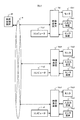
- FIG. 17 is a block diagram showing an example of a video display system according to the seventh embodiment.
- the functions and the like of the present invention described above may be realized by hardware by designing a part or all of them with, for example, an integrated circuit. Further, the microprocessor unit or the like may be realized by software by interpreting and executing an operation program that realizes each function or the like. Hardware and software may be used together.
- control lines and information lines shown in the figure are those that are considered necessary for the explanation, and not all control lines and information lines on the product are necessarily shown. Actually, it may be considered that almost all the components are connected to each other.
- the video display device shown in each of the above embodiments may be configured using the projector shown in the third embodiment.
- 1 video display system 4 network, 10 video display device, 11 video signal source, 12 display object, 20 video processing device
Landscapes
- Engineering & Computer Science (AREA)
- Multimedia (AREA)
- Signal Processing (AREA)
- Human Computer Interaction (AREA)
- Physics & Mathematics (AREA)
- Theoretical Computer Science (AREA)
- General Physics & Mathematics (AREA)
- Computer Hardware Design (AREA)
- Databases & Information Systems (AREA)
- Computer Graphics (AREA)
- General Engineering & Computer Science (AREA)
- Geometry (AREA)
- Computer Security & Cryptography (AREA)
- Data Mining & Analysis (AREA)
- Software Systems (AREA)
- Controls And Circuits For Display Device (AREA)
- Projection Apparatus (AREA)
- Transforming Electric Information Into Light Information (AREA)
Abstract
Priority Applications (6)
| Application Number | Priority Date | Filing Date | Title |
|---|---|---|---|
| CN201580072547.5A CN107113394B (zh) | 2015-01-06 | 2015-01-06 | 影像显示装置、影像显示方法以及影像显示系统 |
| US15/536,676 US10678843B2 (en) | 2015-01-06 | 2015-01-06 | Image display device, image display method and image display system |
| JP2016568195A JP6598800B2 (ja) | 2015-01-06 | 2015-01-06 | 映像表示装置、映像表示方法、及び映像表示システム |
| PCT/JP2015/050142 WO2016110943A1 (fr) | 2015-01-06 | 2015-01-06 | Dispositif d'affichage d'image, procédé d'affichage d'image et système d'affichage d'image |
| US16/862,680 US11106723B2 (en) | 2015-01-06 | 2020-04-30 | Image display device, image display method and image display system |
| US17/383,879 US11829405B2 (en) | 2015-01-06 | 2021-07-23 | Image display device and image display system |
Applications Claiming Priority (1)
| Application Number | Priority Date | Filing Date | Title |
|---|---|---|---|
| PCT/JP2015/050142 WO2016110943A1 (fr) | 2015-01-06 | 2015-01-06 | Dispositif d'affichage d'image, procédé d'affichage d'image et système d'affichage d'image |
Related Child Applications (2)
| Application Number | Title | Priority Date | Filing Date |
|---|---|---|---|
| US15/536,676 A-371-Of-International US10678843B2 (en) | 2015-01-06 | 2015-01-06 | Image display device, image display method and image display system |
| US16/862,680 Continuation US11106723B2 (en) | 2015-01-06 | 2020-04-30 | Image display device, image display method and image display system |
Publications (1)
| Publication Number | Publication Date |
|---|---|
| WO2016110943A1 true WO2016110943A1 (fr) | 2016-07-14 |
Family
ID=56355668
Family Applications (1)
| Application Number | Title | Priority Date | Filing Date |
|---|---|---|---|
| PCT/JP2015/050142 Ceased WO2016110943A1 (fr) | 2015-01-06 | 2015-01-06 | Dispositif d'affichage d'image, procédé d'affichage d'image et système d'affichage d'image |
Country Status (4)
| Country | Link |
|---|---|
| US (3) | US10678843B2 (fr) |
| JP (1) | JP6598800B2 (fr) |
| CN (1) | CN107113394B (fr) |
| WO (1) | WO2016110943A1 (fr) |
Families Citing this family (11)
| Publication number | Priority date | Publication date | Assignee | Title |
|---|---|---|---|---|
| JP6726967B2 (ja) * | 2016-01-19 | 2020-07-22 | 三菱電機株式会社 | 輝度ムラ測定装置 |
| KR102482860B1 (ko) * | 2018-01-02 | 2022-12-30 | 삼성전자 주식회사 | 상황 정보 기반 이미지 처리 방법 및 이를 사용하는 전자 장치 |
| KR102495763B1 (ko) * | 2018-02-23 | 2023-02-06 | 삼성전자주식회사 | 제1 이미지 처리 방식으로 보정된 이미지를 제2 이미지 처리 방식을 이용하여 외부 전자 장치에서 보정하기 위한 전자 장치 및 방법 |
| JP7076246B2 (ja) * | 2018-03-23 | 2022-05-27 | マクセル株式会社 | 撮像装置および撮像システム |
| JP7059835B2 (ja) * | 2018-07-04 | 2022-04-26 | 株式会社島津製作所 | 映像信号圧縮処理装置、映像信号伸張処理装置、映像信号伝送システム、映像信号圧縮処理方法、及び映像信号伸張処理方法 |
| CN112640443B (zh) * | 2018-09-20 | 2023-05-19 | 奥林巴斯株式会社 | 图像处理装置、图像处理方法以及内窥镜系统 |
| KR102618900B1 (ko) * | 2019-01-08 | 2023-12-29 | 삼성전자주식회사 | 디스플레이 장치 및 그 제어 방법 |
| JP7340353B2 (ja) * | 2019-05-22 | 2023-09-07 | 東芝テック株式会社 | 情報処理装置、物品識別装置、及び物品識別システム |
| CN112422933A (zh) * | 2019-08-21 | 2021-02-26 | 台达电子工业股份有限公司 | 投影装置、投影系统以及运行方法 |
| DE102021120037A1 (de) * | 2020-08-21 | 2022-02-24 | Panasonic Intellectual Property Management Co., Ltd. | Videoverarbeitungsvorrichtung und Videoverarbeitungssystem |
| EP4228253B1 (fr) * | 2021-04-22 | 2025-10-08 | Samsung Electronics Co., Ltd. | Dispositif électronique et procédé de commande associé |
Citations (5)
| Publication number | Priority date | Publication date | Assignee | Title |
|---|---|---|---|---|
| JP2003242009A (ja) * | 2002-02-19 | 2003-08-29 | Fuji Photo Film Co Ltd | 画像処理方法および装置並びにプログラム |
| JP2004342003A (ja) * | 2003-05-19 | 2004-12-02 | Fuji Photo Film Co Ltd | 画像処理方法及び装置並びに画像処理システム |
| JP2004362055A (ja) * | 2003-06-02 | 2004-12-24 | Fuji Photo Film Co Ltd | 画像処理方法及び画像処理システム |
| JP2006166064A (ja) * | 2004-12-08 | 2006-06-22 | Ziosoft Inc | 通信端末 |
| JP2011209942A (ja) * | 2010-03-29 | 2011-10-20 | Olympus Imaging Corp | 撮像装置、画像管理サーバ、画像通信システム、画像ファイルのデータ構造、および画像管理方法 |
Family Cites Families (25)
| Publication number | Priority date | Publication date | Assignee | Title |
|---|---|---|---|---|
| WO1994009595A1 (fr) * | 1991-09-20 | 1994-04-28 | Shaw Venson M | Procede et appareil comportant une architecture de systeme destinee a des communications multimedia |
| WO1999067952A1 (fr) * | 1998-06-25 | 1999-12-29 | Hitachi, Ltd. | Procede et dispositif de conversion de nombre de trames de signaux d'images |
| US6487249B2 (en) * | 1998-10-09 | 2002-11-26 | Matsushita Electric Industrial Co., Ltd. | Efficient down conversion system for 2:1 decimation |
| JP4449227B2 (ja) | 2001-02-05 | 2010-04-14 | 株式会社デンソー | 画像処理システム、携帯端末および画像処理サーバ |
| US7369160B2 (en) * | 2001-06-15 | 2008-05-06 | Yokogawa Electric Corporation | Camera system for transferring both image data and an image processing program to transfer the image data to an external device |
| JP2005110148A (ja) | 2003-10-02 | 2005-04-21 | Canon Inc | プロジェクタシステム |
| JP4566679B2 (ja) * | 2003-11-13 | 2010-10-20 | キヤノン株式会社 | 画像形成装置および制御方法およびプログラム |
| JP4374994B2 (ja) | 2003-11-26 | 2009-12-02 | セイコーエプソン株式会社 | プロジェクタ及びプロジェクタシステム |
| US20050129111A1 (en) * | 2003-12-16 | 2005-06-16 | Nokia Corporation | Transform-domain video editing |
| JP4123212B2 (ja) * | 2004-10-01 | 2008-07-23 | 松下電器産業株式会社 | ネットワーク機能を有するプロジェクタ投射システム |
| JPWO2006100820A1 (ja) * | 2005-03-22 | 2008-08-28 | 三菱電機株式会社 | 画像符号化記録読出装置 |
| JP2008178075A (ja) * | 2006-12-18 | 2008-07-31 | Sony Corp | 表示制御装置、表示制御方法、及びプログラム |
| JP2008269486A (ja) * | 2007-04-24 | 2008-11-06 | Olympus Corp | 撮像機器及びその認証方法 |
| JP2009010492A (ja) * | 2007-06-26 | 2009-01-15 | Hitachi Ltd | 画像復号化装置及び画像変換回路 |
| US20110063284A1 (en) * | 2008-05-12 | 2011-03-17 | Tatsuo Sudoh | Image display device, image display method, image display program, reproducing device, reproducing method, reproducing program, and recording medium |
| JP5604827B2 (ja) * | 2009-08-21 | 2014-10-15 | ソニー株式会社 | 送信装置、受信装置、プログラム、及び通信システム |
| JP5609080B2 (ja) | 2009-11-30 | 2014-10-22 | 富士通株式会社 | 画像処理装置、画像表示装置、画像処理プログラム及び画像処理方法 |
| US9406252B2 (en) * | 2009-12-31 | 2016-08-02 | Broadcom Corporation | Adaptive multi-standard video coder supporting adaptive standard selection and mid-stream switch-over |
| JP2012120057A (ja) * | 2010-12-02 | 2012-06-21 | Sony Corp | 画像処理装置、および画像処理方法、並びにプログラム |
| JP2013146049A (ja) * | 2011-12-15 | 2013-07-25 | Sanyo Electric Co Ltd | 画像表示装置および携帯機器 |
| JP5924020B2 (ja) * | 2012-02-16 | 2016-05-25 | セイコーエプソン株式会社 | プロジェクター、及び、プロジェクターの制御方法 |
| US8964062B1 (en) * | 2012-12-18 | 2015-02-24 | Amazon Technologies, Inc. | Integrated light sensor for dynamic exposure adjustment |
| JP2014232167A (ja) * | 2013-05-28 | 2014-12-11 | 株式会社リコー | 画像投射装置および画像投射装置の制御方法 |
| US9177362B2 (en) * | 2013-08-02 | 2015-11-03 | Facebook, Inc. | Systems and methods for transforming an image |
| US20160234523A1 (en) * | 2013-09-06 | 2016-08-11 | Mitsubishi Electric Corporation | Video encoding device, video transcoding device, video encoding method, video transcoding method, and video stream transmission system |
-
2015
- 2015-01-06 WO PCT/JP2015/050142 patent/WO2016110943A1/fr not_active Ceased
- 2015-01-06 CN CN201580072547.5A patent/CN107113394B/zh active Active
- 2015-01-06 JP JP2016568195A patent/JP6598800B2/ja active Active
- 2015-01-06 US US15/536,676 patent/US10678843B2/en active Active
-
2020
- 2020-04-30 US US16/862,680 patent/US11106723B2/en active Active
-
2021
- 2021-07-23 US US17/383,879 patent/US11829405B2/en active Active
Patent Citations (5)
| Publication number | Priority date | Publication date | Assignee | Title |
|---|---|---|---|---|
| JP2003242009A (ja) * | 2002-02-19 | 2003-08-29 | Fuji Photo Film Co Ltd | 画像処理方法および装置並びにプログラム |
| JP2004342003A (ja) * | 2003-05-19 | 2004-12-02 | Fuji Photo Film Co Ltd | 画像処理方法及び装置並びに画像処理システム |
| JP2004362055A (ja) * | 2003-06-02 | 2004-12-24 | Fuji Photo Film Co Ltd | 画像処理方法及び画像処理システム |
| JP2006166064A (ja) * | 2004-12-08 | 2006-06-22 | Ziosoft Inc | 通信端末 |
| JP2011209942A (ja) * | 2010-03-29 | 2011-10-20 | Olympus Imaging Corp | 撮像装置、画像管理サーバ、画像通信システム、画像ファイルのデータ構造、および画像管理方法 |
Also Published As
| Publication number | Publication date |
|---|---|
| CN107113394A (zh) | 2017-08-29 |
| US10678843B2 (en) | 2020-06-09 |
| US11829405B2 (en) | 2023-11-28 |
| JP6598800B2 (ja) | 2019-10-30 |
| CN107113394B (zh) | 2019-10-18 |
| US20170344543A1 (en) | 2017-11-30 |
| JPWO2016110943A1 (ja) | 2017-10-26 |
| US20200257719A1 (en) | 2020-08-13 |
| US11106723B2 (en) | 2021-08-31 |
| US20210349934A1 (en) | 2021-11-11 |
Similar Documents
| Publication | Publication Date | Title |
|---|---|---|
| JP6598800B2 (ja) | 映像表示装置、映像表示方法、及び映像表示システム | |
| CN110460745B (zh) | 显示装置 | |
| CN105493490B (zh) | 变换方法和变换装置 | |
| US8269899B2 (en) | Electronic device, method for responding to message, and program | |
| US20140313366A1 (en) | Method of processing image and electronic device and system supporting the same | |
| US20160353096A1 (en) | Display device and image quality setting method | |
| US10303419B2 (en) | Information processing system, display processing apparatus, display processing method, and recording medium | |
| US20200275155A1 (en) | Display device and image display method of the same | |
| JP2018004919A (ja) | 表示装置およびその制御方法 | |
| JP2016014713A (ja) | 画像投影装置、画像投影方法および画像投影装置の制御プログラム | |
| CN108881743A (zh) | 一种基于拼接墙的视频图像处理方法、装置及系统 | |
| US11263730B2 (en) | Image processing method and apparatus and terminal device | |
| JP5904754B2 (ja) | 情報処理システム、情報処理装置、それらの制御方法、およびプログラム | |
| US8786627B2 (en) | Method for displaying video signal dithered by related masks and video display apparatus applying the same | |
| JP3112392U (ja) | Hdtv | |
| CN109429099A (zh) | 用于播放媒体文件的方法、处理器和媒体播放设备 | |
| US12457427B2 (en) | Information processing apparatus, method, medium, and system for color correction | |
| US20110157153A1 (en) | Projection-type image display apparatus provided with an image pickup function | |
| JP2018004801A (ja) | 画像表示装置 | |
| US20180376031A1 (en) | Projection apparatus that improves dynamic range of luminance of printed material, control method therefor, and storage medium | |
| JP2010032920A (ja) | 映像表示装置及び映像表示方法 | |
| EP4576789A1 (fr) | Dispositif d'affichage et son procédé de fonctionnement | |
| JP2015142275A (ja) | 画像処理装置、画像処理方法、表示装置、表示方法、及び、プログラム | |
| JP2019114889A (ja) | 投影装置および投影装置の較正方法 | |
| EP4660777A1 (fr) | Dispositif électronique et procédé de fonctionnement associé |
Legal Events
| Date | Code | Title | Description |
|---|---|---|---|
| 121 | Ep: the epo has been informed by wipo that ep was designated in this application |
Ref document number: 15876821 Country of ref document: EP Kind code of ref document: A1 |
|
| WWE | Wipo information: entry into national phase |
Ref document number: 15536676 Country of ref document: US |
|
| ENP | Entry into the national phase |
Ref document number: 2016568195 Country of ref document: JP Kind code of ref document: A |
|
| NENP | Non-entry into the national phase |
Ref country code: DE |
|
| 122 | Ep: pct application non-entry in european phase |
Ref document number: 15876821 Country of ref document: EP Kind code of ref document: A1 |