WO2016110960A1 - Base de conditionneur d'air - Google Patents
Base de conditionneur d'air Download PDFInfo
- Publication number
- WO2016110960A1 WO2016110960A1 PCT/JP2015/050271 JP2015050271W WO2016110960A1 WO 2016110960 A1 WO2016110960 A1 WO 2016110960A1 JP 2015050271 W JP2015050271 W JP 2015050271W WO 2016110960 A1 WO2016110960 A1 WO 2016110960A1
- Authority
- WO
- WIPO (PCT)
- Prior art keywords
- air conditioner
- drain
- drain pan
- housing
- frame
- Prior art date
- Legal status (The legal status is an assumption and is not a legal conclusion. Google has not performed a legal analysis and makes no representation as to the accuracy of the status listed.)
- Ceased
Links
Images




Classifications
-
- F—MECHANICAL ENGINEERING; LIGHTING; HEATING; WEAPONS; BLASTING
- F24—HEATING; RANGES; VENTILATING
- F24F—AIR-CONDITIONING; AIR-HUMIDIFICATION; VENTILATION; USE OF AIR CURRENTS FOR SCREENING
- F24F13/00—Details common to, or for air-conditioning, air-humidification, ventilation or use of air currents for screening
- F24F13/22—Means for preventing condensation or evacuating condensate
-
- F—MECHANICAL ENGINEERING; LIGHTING; HEATING; WEAPONS; BLASTING
- F24—HEATING; RANGES; VENTILATING
- F24F—AIR-CONDITIONING; AIR-HUMIDIFICATION; VENTILATION; USE OF AIR CURRENTS FOR SCREENING
- F24F13/00—Details common to, or for air-conditioning, air-humidification, ventilation or use of air currents for screening
- F24F13/32—Supports for air-conditioning, air-humidification or ventilation units
Definitions
- the present invention relates to a frame for an air conditioner, and more particularly to a frame structure including a drain pan that collects drain water generated in the air conditioner body.
- the gantry proposed in Patent Document 1 has a structure that can collect all the dew in the air conditioner with one drain pan.
- Patent Document 1 there is no problem as long as all dew can be collected with one drain pan, but there is a restriction on the installation structure of the drain pan, and all dew cannot be collected with one drain pan.
- dew remaining in the air conditioner may cause mold generation, corrosion, or dripping outside the machine. That is, there is a risk of dew collection and drainage problems.
- patent document 1 although it has a structure which can collect
- the drain pan when the drain pan is in contact with the side plate of the gantry, the cold dew collected in the drain pan cools the side plate.
- the side plate is cooled, dew is generated on the design surface of the surface of the side plate due to a temperature difference between the side plate and the outside air (around the side plate), and the dew grows, and there is a risk of dew dripping.
- the present invention has been made to solve the above-described problems, and is a frame for an air conditioner that collects all the dew in the air conditioner main body and prevents the side plate surface from generating dew.
- the purpose is to provide.
- the frame of the air conditioner according to the present invention includes a casing on which an air conditioner main body is placed, a drain pan disposed in the casing at a distance from an inner wall of the casing, and an inner wall of the casing. And a drain guide that protrudes and covers an edge of the drain pan.
- the drain pan disposed in the casing at a distance from the inner wall of the casing, the inner wall of the casing is provided so as to protrude inward, and an end portion of the drain pan is provided. And a drain guide covering the edge. Since the drain guide receives the dew of the portion that cannot be collected by the drain pan and guides it to the drain pan, all the dew can be discharged to the outside drain without leaking outside the machine. Further, since the drain pan is disposed with a space from the inner wall of the housing and is not in contact with the inner wall, even if cold dew is collected in the drain pan, the side plate of the housing is not cooled. For this reason, a state where dew is generated on the design surface of the side plate surface due to a temperature difference between the side plate and the outside air (around the side plate) as in the prior art can be avoided.
- FIG. 4 is a top view of the gantry of FIG. 3.
- FIG. 3 is a top view of the gantry of FIG. 2. It is the figure which looked at the drain guide of FIG. 2 from the side.
- FIG. 3 is a bottom view of the drain pan of FIG. 2.
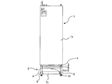
- FIG. 1 is a front view of an air conditioner according to Embodiment 1 of the present invention.
- the air conditioner includes an air conditioner body 1 and a gantry 2, and the air conditioner body 1 is fixed on the gantry 2.
- the air conditioner body 1 constitutes, for example, an indoor unit, and incorporates an indoor heat exchanger, a blower, and the like (none of which are shown) that constitute a part of the refrigeration cycle.
- the housing 1a that forms the outer shell of the air conditioner body 1 has a suction port at the back and a discharge port at the top (top plate side) (none of them are shown).
- the air conditioner body 1 takes in outside air from the suction port provided in the housing 1a by driving the blower, and discharges the air heat-exchanged by the indoor heat exchanger from the discharge port provided in the housing 1a. To do. As described above, the air heat-exchanged by the indoor heat exchanger, for example, cooled air, is discharged from the discharge port, but the indoor heat exchanger and the refrigerant pipe in the housing 1a are cooled, so The air is cooled and dew is generated. The dew drops on the gantry 2 disposed below the air conditioner main body 1. In the present embodiment, the dew is processed in the gantry 2 described below.
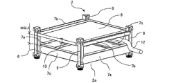
- FIG. 2 is a perspective view of the gantry 2 of FIG.
- the gantry 2 includes a housing 2a that forms the outline of the gantry 2.
- the housing 2a as a whole has a structure opened in the vertical direction.
- the housing 2a includes left and right side plates 4 and a front plate (front side plate) 5 and is open in the vertical direction.
- the left and right side plates 4 include plate-shaped drain guides 3a attached to the upper portion so as to protrude inward.
- the front plate 5 includes a plate-like drain guide 3b attached to the upper portion so as to protrude inward.
- a drain pan 8 is disposed below the drain guide 3a and the drain guide 3b.
- the end portions of the drain guide 3 a and the drain guide 3 b are in a positional relationship so as to cover the edge (periphery) of the drain pan 8.
- Two (a plurality) knockout holes 11 are provided on the upper left and right sides of the left and right side plates 4.
- a knockout hole is a hole that has been machined into a tool so that it can be easily drilled in the field during installation.
- a drain hose 12 is disposed through one knockout hole 11.
- FIG. 3 is a view showing a state in which the left and right side plates 4 and the front plate 5 are removed from the housing 2a of the gantry 2 in FIG.
- the casing 2a of the gantry 2 includes four support columns 6 each having a U-shaped cross section disposed at four corners (corners) of a rectangular shape in plan view. For convenience, it is referred to as a U-shaped cross section.
- This U-shaped cross section refers to a shape obtained by removing one side of a quadrilateral consisting of four sides, and the corners are right angles.
- the casing 2a further includes U-shaped horizontal frame members 7a and 7b that connect the front and rear columns 6 and U-shaped horizontal frame members 7c that connect the left and right columns 6 respectively.
- the materials 7a, 7b, and 7c are fixed to the column 6 with screws or the like.
- the drain pan 8 has a square box shape, and is fixed to the horizontal frame member 7b with screws or the like. That is, the drain pan 8 is not directly attached to the left and right side plates 4 and the front plate 5 in FIG. 2, but is attached to the column 6 via the horizontal frame member 7b.
- the drain pan 8 is provided with a drain socket 10 that can rotate through the drain pan 8, and a drain hose 12 is connected to the drain socket 10.
- the bottom of the drain pan 8 is inclined downward with respect to the front side (drain socket 10 side), and is configured such that the accumulated water flows to the drain socket 10 side. Further, the left and right side plates 4 and the front plate 5 are detachably attached to the column 6 independently from the housing 2a.
- the left and right side plates 4, the front plate 5, the support column 6, and the lateral frame members 7a to 7c constitute the casing 2a of the present invention (see FIG. 1).
- the materials 7a to 7c constitute the frame member of the present invention.
- the configurations of the support column 6 and the lateral frame members 7a to 7c are not limited to the shapes described in FIG. 3, and may be other configurations as long as they function as frame members (for example, the cross-section L Shape, prism, etc.).
- FIG. 4 is a diagram showing a state in which the left and right side plates 4 and the front plate 5 are removed from the housing 2a of the gantry 2 in FIG.
- the air conditioner main body 1 is placed on the upper surface of the four columns 6 of the housing 2a.
- the air conditioner body 1 and the gantry 2 (housing 2a) are fixed with screws or the like.
- by providing a clearance of 25 mm or more between the bottom plate 9 of the air conditioner body 1 and the drain pan 8 there is no risk of a finger being caught in the gap between the bottom plate 9 of the air conditioner body 1 and the drain pan 8 during assembly. It can be carried out.
- dew is generated in the air conditioner body 1 due to a temperature difference between the refrigerant flowing in the air conditioner body 1 and the outside air.
- the dew accumulates on the bottom plate 9 of the air conditioner main body 1, but drops from the hole provided in the bottom plate 9 of the air conditioner main body 1 to the drain pan 8 and is discharged to the outside through the drain socket 10 and the drain hose 12. Is done.
- FIG. 5 is a top view of the gantry 2 of FIG. That is, FIG. 5 shows a state in which the left and right side plates 4 and the front plate 5 are removed from the housing 2a and there are no drain guides 3a and 3b.
- the drain pan 8 is disposed inside the four columns 6. For this reason, a space of X and Y is generated between which the dew cannot be collected between the inside of the bottom plate 9 of the air conditioner body 1 and the outside of the drain pan 8. That is, when dew is dropped on the area indicated by the symbol a in FIG. 5, the drain pan 8 cannot collect the dew. This point is solved by the installation of drain guides 3a and 3b.
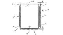
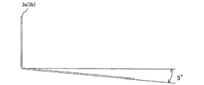
- FIG. 6 is a top view of the gantry 2 of FIG. 2, and FIG. 7 is a side view of the drain guides 3a and 3b of FIG.
- FIG. 6 shows a state in which the left and right side plates 4 and the front plate 5 are attached to the column 6.
- Drain guides 3 a and 3 b are attached to the left and right side plates 4 and the front plate 5, and the drain guides 3 a and 3 b are filled with the end portion (drain guides 3 a and 3 b) so as to fill the area indicated by the symbol a. Is arranged so as to cover the edge of the drain pan 8.
- the drain guides 3a and 3b By arranging the drain guides 3a and 3b in this manner, the dew dripped on the drain guides 3a and 3b is dripped onto the drain guides 3a and 3b.
- the dew dropped on the drain guides 3 a and 3 b is guided to the drain pan 8. That is, in the present embodiment, the dew in all the areas including the area indicated by the symbol a can be collected, so that it is possible to prevent the occurrence of mold, corrosion, and dripping outside the machine. It has become. Further, by taking the distance between the drain pan 8 and the left and right side plates 4 and the front plate 5, the left and right side plates 4 and the front plate 5 are not affected by the heat of the cooled drain pan 8.
- FIG. 8 is a bottom view of the drain pan 8 of FIG.
- the drain pan 8 is provided with a rotatable drain socket 10 on the front side in the center in the width direction.
- the knockout holes 11 are provided on the upper left and right sides of the left and right side plates 4. Since the gantry 2 is configured so that the left and right side plates 4 and the front plate 5 are detachable independently (see FIGS. 2 and 3), the gantry 2 should be attached to the air conditioner body 1 without any restriction in the front-rear direction. Is possible. That is, the front side of the gantry 2 may be the back side, and the back side may be the front side. It can be installed according to local needs. Moreover, since the knockout hole 11 (refer FIG. 2) is provided in the upper left and right of the left and right side plates 4, the drainage hose connected to the drain socket 10 using any knockout hole 11 according to the local situation. 12 can be routed and drained.
- the clearance gap between the horizontal frame material 7c of the front side of the mount frame 2 and the drain pan 8 may be 80 mm or more (refer FIG. 3).
- This gap is set to allow a human hand to enter in consideration of the maintenance space.
- pillar 6 is 270 mm, for example, it can be drawn about 10 m with the 1/100 gradient of the drainage hose 12, and drainage is made easy.
- the drain guides 3a and 3b receive dew from an area that cannot be collected by the drain pan 8 (see a in FIGS. 5 and 6) and guide it to the drain pan 8 to flow. For this reason, all the dew can be discharged to the external drainage groove without leaking outside the apparatus.
- the drain pan 8 since the drain pan 8 is not in contact with the inner wall of the housing 2a (the inner walls of the left and right side plates 4 and the front plate 5), even if cold dew is collected in the drain pan 8, the side wall of the housing 2a is cooled. There is no. For this reason, a state where dew is generated on the design surface of the side plate surface due to a temperature difference between the side plate and the outside air (around the side plate) as in the prior art can be avoided.
- Air conditioner body 1a housing, 2 base, 2a housing, 3a, 3b drain guide, 4 side plate, 5 front plate, 6 struts, 7a-7c horizontal frame material, 8 drain pan, 9 air conditioner body 1 Bottom plate, 10 drain socket, 11 knockout holes, 12 drainage hose.
Landscapes
- Engineering & Computer Science (AREA)
- Chemical & Material Sciences (AREA)
- Combustion & Propulsion (AREA)
- Mechanical Engineering (AREA)
- General Engineering & Computer Science (AREA)
- Devices For Blowing Cold Air, Devices For Blowing Warm Air, And Means For Preventing Water Condensation In Air Conditioning Units (AREA)
- Air Filters, Heat-Exchange Apparatuses, And Housings Of Air-Conditioning Units (AREA)
Abstract
L'invention concerne une base de conditionneur d'air (2) équipée comme suit : un corps de boîte (2a) sur lequel un corps de conditionneur d'air (1) est placé ; un bac de récupération (8) disposé à l'intérieur du corps de boîte (2a) selon un intervalle par rapport à des parois internes du corps de boîte (2a) de manière à ne pas entrer en contact avec celui-ci ; et des guides de récupération (3a, 3b) qui sont mis en œuvre au niveau des parois intérieures du corps de boîte (2a) de manière à faire saillie vers l'intérieur et dont les extrémités recouvrent les bords du bac de récupération. Toute rosée qui ne peut pas être recueillie par le bac de récupération (8) est reçue par les guides de récupération (3a, 3b) et guidée dans le bac de récupération (8).
Priority Applications (2)
| Application Number | Priority Date | Filing Date | Title |
|---|---|---|---|
| PCT/JP2015/050271 WO2016110960A1 (fr) | 2015-01-07 | 2015-01-07 | Base de conditionneur d'air |
| JP2016568209A JP6444432B2 (ja) | 2015-01-07 | 2015-01-07 | 空気調和機の架台 |
Applications Claiming Priority (1)
| Application Number | Priority Date | Filing Date | Title |
|---|---|---|---|
| PCT/JP2015/050271 WO2016110960A1 (fr) | 2015-01-07 | 2015-01-07 | Base de conditionneur d'air |
Publications (1)
| Publication Number | Publication Date |
|---|---|
| WO2016110960A1 true WO2016110960A1 (fr) | 2016-07-14 |
Family
ID=56355683
Family Applications (1)
| Application Number | Title | Priority Date | Filing Date |
|---|---|---|---|
| PCT/JP2015/050271 Ceased WO2016110960A1 (fr) | 2015-01-07 | 2015-01-07 | Base de conditionneur d'air |
Country Status (2)
| Country | Link |
|---|---|
| JP (1) | JP6444432B2 (fr) |
| WO (1) | WO2016110960A1 (fr) |
Cited By (3)
| Publication number | Priority date | Publication date | Assignee | Title |
|---|---|---|---|---|
| CN107062579A (zh) * | 2017-04-27 | 2017-08-18 | 广东电网有限责任公司中山供电局 | 变电站柜式空调二次排水装置 |
| CN115727247A (zh) * | 2022-10-24 | 2023-03-03 | 国网浙江省电力有限公司杭州市临平区供电公司 | 一种精密空调故障报警装置安装支架 |
| JP2023030659A (ja) * | 2021-08-23 | 2023-03-08 | 株式会社イーズ | 空気調和装置 |
Citations (3)
| Publication number | Priority date | Publication date | Assignee | Title |
|---|---|---|---|---|
| JPS5350922U (fr) * | 1976-10-05 | 1978-04-28 | ||
| JPS6023621U (ja) * | 1983-07-25 | 1985-02-18 | 株式会社日立製作所 | 空調機 |
| JPH05322210A (ja) * | 1992-05-15 | 1993-12-07 | Daikin Ind Ltd | 空気調和装置 |
Family Cites Families (3)
| Publication number | Priority date | Publication date | Assignee | Title |
|---|---|---|---|---|
| JPS53145745U (fr) * | 1977-04-22 | 1978-11-16 | ||
| JP5758681B2 (ja) * | 2011-04-14 | 2015-08-05 | 三菱電機株式会社 | 冷凍サイクル装置の室外機 |
| JP5884784B2 (ja) * | 2013-04-12 | 2016-03-15 | ダイキン工業株式会社 | チラー装置 |
-
2015
- 2015-01-07 JP JP2016568209A patent/JP6444432B2/ja not_active Expired - Fee Related
- 2015-01-07 WO PCT/JP2015/050271 patent/WO2016110960A1/fr not_active Ceased
Patent Citations (3)
| Publication number | Priority date | Publication date | Assignee | Title |
|---|---|---|---|---|
| JPS5350922U (fr) * | 1976-10-05 | 1978-04-28 | ||
| JPS6023621U (ja) * | 1983-07-25 | 1985-02-18 | 株式会社日立製作所 | 空調機 |
| JPH05322210A (ja) * | 1992-05-15 | 1993-12-07 | Daikin Ind Ltd | 空気調和装置 |
Cited By (4)
| Publication number | Priority date | Publication date | Assignee | Title |
|---|---|---|---|---|
| CN107062579A (zh) * | 2017-04-27 | 2017-08-18 | 广东电网有限责任公司中山供电局 | 变电站柜式空调二次排水装置 |
| CN107062579B (zh) * | 2017-04-27 | 2019-10-22 | 广东电网有限责任公司中山供电局 | 变电站柜式空调二次排水装置 |
| JP2023030659A (ja) * | 2021-08-23 | 2023-03-08 | 株式会社イーズ | 空気調和装置 |
| CN115727247A (zh) * | 2022-10-24 | 2023-03-03 | 国网浙江省电力有限公司杭州市临平区供电公司 | 一种精密空调故障报警装置安装支架 |
Also Published As
| Publication number | Publication date |
|---|---|
| JPWO2016110960A1 (ja) | 2017-06-01 |
| JP6444432B2 (ja) | 2018-12-26 |
Similar Documents
| Publication | Publication Date | Title |
|---|---|---|
| JP5310887B2 (ja) | 室外機及び冷凍装置 | |
| EP2950625B1 (fr) | Appareil électrique | |
| JP6578011B2 (ja) | 電子筐体ラインおよび前記電子筐体ラインに接続される冷却機を備える電子筐体装置 | |
| GB2539116A (en) | Indoor unit for air-conditioning device | |
| JP6444432B2 (ja) | 空気調和機の架台 | |
| JP6048818B2 (ja) | 室外ユニット | |
| CN105188352B (zh) | 鸡舍用空气冷却装置 | |
| EP4109000A1 (fr) | Unité extérieure pour dispositif à cycle frigorifique | |
| CN104081129B (zh) | 制冷装置的室外单元 | |
| JP6120209B2 (ja) | 室外ユニット | |
| JP6524217B2 (ja) | 天井埋込形空気調和装置 | |
| JP2005098572A (ja) | 冷却装置 | |
| JP6618624B2 (ja) | 空気調和機の室外機 | |
| WO2012002424A1 (fr) | Dispositif de soufflage d'air | |
| JP5921924B2 (ja) | 製氷機 | |
| JP5137868B2 (ja) | ドレンアップ装置及びこれを備えた空気調和機 | |
| US20180088451A1 (en) | Cooling device | |
| US9877418B2 (en) | Motor drive device in which fan motor is exchangeable and control panel including same | |
| JP2017053559A (ja) | 空気調和機の室内機 | |
| JP6400208B2 (ja) | 空調用室内機 | |
| CN210463316U (zh) | 一种电控盒、空调外机及空调系统 | |
| JP2023092148A (ja) | 熱交換型換気装置 | |
| CN207936451U (zh) | 空调室内机 | |
| US20170108230A1 (en) | Heat exchange unit and air-conditioning apparatus | |
| JP6115855B2 (ja) | 室外ユニット |
Legal Events
| Date | Code | Title | Description |
|---|---|---|---|
| 121 | Ep: the epo has been informed by wipo that ep was designated in this application |
Ref document number: 15876838 Country of ref document: EP Kind code of ref document: A1 |
|
| ENP | Entry into the national phase |
Ref document number: 2016568209 Country of ref document: JP Kind code of ref document: A |
|
| NENP | Non-entry into the national phase |
Ref country code: DE |
|
| 122 | Ep: pct application non-entry in european phase |
Ref document number: 15876838 Country of ref document: EP Kind code of ref document: A1 |