WO2016111141A1 - 扉の開閉検知装置 - Google Patents
扉の開閉検知装置 Download PDFInfo
- Publication number
- WO2016111141A1 WO2016111141A1 PCT/JP2015/085512 JP2015085512W WO2016111141A1 WO 2016111141 A1 WO2016111141 A1 WO 2016111141A1 JP 2015085512 W JP2015085512 W JP 2015085512W WO 2016111141 A1 WO2016111141 A1 WO 2016111141A1
- Authority
- WO
- WIPO (PCT)
- Prior art keywords
- door
- opening
- closing
- doors
- lock
- Prior art date
- Legal status (The legal status is an assumption and is not a legal conclusion. Google has not performed a legal analysis and makes no representation as to the accuracy of the status listed.)
- Ceased
Links
Images



Classifications
-
- E—FIXED CONSTRUCTIONS
- E05—LOCKS; KEYS; WINDOW OR DOOR FITTINGS; SAFES
- E05B—LOCKS; ACCESSORIES THEREFOR; HANDCUFFS
- E05B41/00—Locks with visible indication as to whether the lock is locked or unlocked
-
- E—FIXED CONSTRUCTIONS
- E05—LOCKS; KEYS; WINDOW OR DOOR FITTINGS; SAFES
- E05B—LOCKS; ACCESSORIES THEREFOR; HANDCUFFS
- E05B47/00—Operating or controlling locks or other fastening devices by electric or magnetic means
-
- E—FIXED CONSTRUCTIONS
- E05—LOCKS; KEYS; WINDOW OR DOOR FITTINGS; SAFES
- E05F—DEVICES FOR MOVING WINGS INTO OPEN OR CLOSED POSITION; CHECKS FOR WINGS; WING FITTINGS NOT OTHERWISE PROVIDED FOR, CONCERNED WITH THE FUNCTIONING OF THE WING
- E05F7/00—Accessories for wings not provided for in other groups of this subclass
Definitions
- the present invention relates to a detection device that detects and locks the opening and closing of a door provided on a housing of various devices, a housing that forms a predetermined space inside, a partition wall that partitions the space, and the like.
- the processing apparatus Since various processing apparatuses used in the manufacturing process of a semiconductor device process a semiconductor substrate using a processing liquid or a processing gas, the processing apparatus includes a housing for making the inside a sealed space partitioned from the external environment. In this way, the dispersion of the processing liquid and the leakage of the processing gas are prevented. Since various consumables are used in the processing apparatus, they must be periodically replaced. In addition, since the processing apparatus is a collection of various precision devices, maintenance and inspection of the devices are required. Therefore, a plurality of doors that can be opened and closed are provided in the housing of the processing apparatus.
- processing apparatus when the door is opened and closed for replacement of consumables, maintenance and inspection of equipment, etc., the opening and closing of the door is detected and the processing apparatus is interlocked.
- processing equipment such as semiconductor manufacturing equipment
- industrial machines generally have equipment and facilities that are equipped with doors that can be opened and closed.
- door installation, opening / closing detection, and locking are performed. It has been broken.
- FIG. 7 is a schematic perspective view showing a conventional example of a detection device that detects opening and closing of a door.
- the two adjacent left and right doors 3, 3 are of a double door type that rotates in the opposite direction and opens forward.
- a rectangular opening 31 is formed in the portion covered by the two doors 3, 3, and one door switch corresponding to one door 3 is formed at the upper end of the opening 31.
- 35 is installed.
- the opening 31 is not limited to a rectangular shape, and may have another shape.
- Each door switch 35 is connected to a control unit (not shown) via an electric wire 36.
- the opening and closing of the doors 3 and 3 are detected by the door switches 35 and 35, and the opening and closing signals are output from the door switches 35 and 35, respectively.
- the present invention has been made in view of the above-described circumstances. With respect to a plurality of doors, the opening and closing of each door can be detected with a single door switch, and each door can be detected with a single electrically controlled lock mechanism.
- An object of the present invention is to provide a door open / close detection device capable of locking the door.
- a door open / close detection device is a door open / close detection device that detects the opening / closing of two or more doors installed in an opening, and A common single door switch is provided, and the door switch includes two or more door opening / closing detectors corresponding to each of the two or more doors, and an output circuit of the two or more door opening / closing detectors is It is characterized by being connected in series or in parallel in the door switch. According to the present invention, by providing a circuit in which two or more door opening / closing detectors are connected in series or in parallel inside the door switch, one door switch can perform opening / closing detection output of two or more doors. it can.
- the door switch includes a door lock coil portion that operates one electromagnetic coil with a single control input to lock the two or more doors.
- one electromagnetic coil can be operated and one or more doors can be locked by one point of control input into the electric control type lock mechanism.
- the door lock coil portion includes the one electromagnetic coil and an electromagnetic coil shaft that moves by the operation of the electromagnetic coil, and the electromagnetic coil shaft is operated by the operation of the electromagnetic coil.
- Two or more locking levers that engage with lock keys respectively fixed to the two or more doors are provided.
- the electromagnetic coil when the electromagnetic coil is turned on, the electromagnetic coil shaft is pushed by the attractive force of the electromagnetic coil, and the two or more locking levers are respectively engaged with the lock key, for example, fitted in the hole of the lock key. Combined. Thereby, the lock mechanism is in a locked state.
- the door switch includes a door lock coil portion that operates two or more electromagnetic coils connected in parallel with a single control input to lock the two or more doors. It is characterized by. According to the present invention, two or more doors can be simultaneously locked by using two or more electromagnetic coils connected in parallel with one control input to the inside of the electric control type lock mechanism.
- the door switch includes a contact of an output circuit of the door opening / closing detection unit on a primary side or a secondary side of the door lock coil unit.
- the contact of the door open / close detection output circuit is inserted on the primary side or the secondary side of the electromagnetic coil circuit for locking.
- the contact points of the output circuits of the two or more door opening / closing detection units are connected in series or in parallel.
- the present invention has the following effects. (1) With respect to multiple doors, it is possible to detect the opening and closing of each door with a single door switch, and it is possible to lock each door with a single electrically controlled lock mechanism, reducing the number of parts. Yes. (2) Opening / closing of each door can be detected with a single door switch for a plurality of doors, and each door can be locked with a single electric control type lock mechanism.
- a serial connection / parallel connection circuit can be provided inside the control-type lock mechanism, eliminating the need for an external circuit and a power supply / signal transmission wire. Moreover, although the electric wire connection had to be made in the vicinity of each door switch or the electric control type lock mechanism, the connection at one place becomes possible.
- each door With respect to a plurality of doors, the opening / closing of each door can be detected with one door switch, and each door can be locked with one electric control type lock mechanism.
- the control operation I / O can also be operated at one point. Further, depending on the detection / operation conditions, it is possible to divide the I / O by detecting with a door switch of a plurality of types of circuits, or providing an electrically controlled lock mechanism.
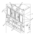
- FIG. 1 is a schematic perspective view showing an overall configuration of a polishing apparatus provided with a door open / close detection device according to the present invention.
- FIG. 2 is a view showing a main part of the housing, and is a perspective view showing a door provided in the housing and its periphery.
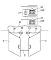
- FIG. 3A is a schematic diagram showing a conventional door opening / closing detection device, and is shown in comparison with the door opening / closing detection device according to the present invention shown in FIG. 3B.
- FIG. 3B is a schematic diagram showing a door opening / closing detection device according to the present invention, which is shown in comparison with the conventional door opening / closing detection device shown in FIG. 3A.
- FIG. 3A is a schematic perspective view showing an overall configuration of a polishing apparatus provided with a door open / close detection device according to the present invention.
- FIG. 2 is a view showing a main part of the housing, and is a perspective view showing a door provided in the housing and its periphery.
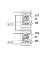
- FIG. 4A is a circuit diagram showing a conventional electric control type door lock mechanism, which is shown in comparison with the electric control type door lock mechanism according to the present invention shown in FIG. 4B.
- FIG. 4B is a circuit diagram showing an electrically controlled door lock mechanism according to the present invention, which is shown in comparison with the conventional electrically controlled door lock mechanism shown in FIG. 4A.
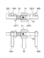
- FIG. 5A is a schematic diagram illustrating a mechanical structure of a lock mechanism that is preferably used in the electric control type door lock mechanism having a single coil circuit shown on the upper side of FIG. 4B, and shows an unlocked state of the lock mechanism.
- FIG. 4A is a circuit diagram showing a conventional electric control type door lock mechanism, which is shown in comparison with the electric control type door lock mechanism according to the present invention shown in FIG. 4B.
- FIG. 4B is a circuit diagram showing an electrically controlled door lock mechanism according to the present invention, which is shown in comparison with the conventional electrically controlled door lock mechanism shown in FIG. 4A.
- FIG. 5A is
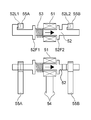
- FIG. 5B is a schematic diagram illustrating a mechanical structure of a lock mechanism that is preferably used for the electric control type door lock mechanism having a single coil circuit shown on the upper side of FIG. 4B, and shows a locked state of the lock mechanism.
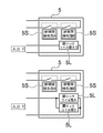
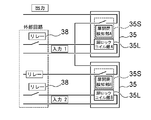
- FIG. 6A is a circuit diagram showing a conventional electric control type door lock mechanism, and is a circuit diagram in which a circuit for creating operating conditions is added to the conventional electric control type door lock mechanism shown in FIG. 4A.
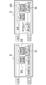
- 6B is a circuit diagram showing an electrically controlled door lock mechanism according to the present invention, and is a circuit diagram in which a circuit for creating operating conditions is added to the electrically controlled door lock mechanism according to the present invention shown in FIG. 4B.
- FIG. 6C is a circuit diagram showing an electrically controlled door lock mechanism according to the present invention, and is a circuit diagram in which a circuit for creating operating conditions is added to the electrically controlled door lock mechanism according to the present invention shown in FIG. 4B.
- FIG. 7 is a schematic perspective view showing a conventional example of a detection device that detects opening and closing of a door.
- FIGS. 1 to 6C 1 to 6C, the same or corresponding components are denoted by the same reference numerals, and redundant description is omitted.
- FIG. 1 is a schematic perspective view showing a polishing apparatus (CMP apparatus) as an example of a processing apparatus provided with a door opening / closing detection apparatus according to the present invention.
- CMP apparatus polishing apparatus
- the case of a polishing apparatus will be described as a processing apparatus having a door opening / closing device.
- the door opening / closing detection device according to the present invention is provided on a housing or partition wall of various devices. It can also be applied to a gate for limiting access to the production line.
- FIG. 1 is a schematic perspective view showing the overall configuration of the polishing apparatus. As shown in FIG. 1, the entire polishing apparatus is covered with a substantially rectangular parallelepiped housing 1, and the interior of the polishing apparatus is isolated from the external environment. At one end of the polishing apparatus, there is provided a load / unload unit 2 for placing a cassette for stocking a substrate such as a semiconductor wafer.
- the load / unload unit 2 can be equipped with an open cassette, a SMIF (Standard Manufacturing Interface) pod, or a FOUP (Front Opening Unified Pod).
- SMIF Standard Manufacturing Interface
- FOUP Front Opening Unified Pod
- the substrate is taken out from the load / unload unit 2 by the transfer mechanism in the housing 1 and transferred to the polishing unit, and the polishing unit (slurry) is supplied to the polishing pad in the polishing unit.
- the substrate is polished by pressing against the polishing pad.
- the polished substrate is transported to the cleaning section by the transport mechanism, and is cleaned and dried by the cleaning liquid in the cleaning section.
- the cleaned substrate is returned to the load / unload unit 2 by the transport mechanism.
- CMP apparatus polishing apparatus
- the polishing apparatus since the polishing apparatus processes the substrate using a processing liquid such as a polishing liquid or a cleaning liquid, the polishing apparatus includes a housing 1 for making the inside a sealed space that is partitioned from the external environment. Gas leakage caused by scattering or volatilization of the processing liquid is prevented. Since various consumables are used in the polishing apparatus, they must be periodically replaced. In addition, since the polishing apparatus is a collection of various precision devices, maintenance and inspection of the devices are required. Therefore, the housing 1 of the polishing apparatus is provided with a plurality of doors 3 that can be opened and closed. The door 3 is also used when a product (substrate) to be processed is manually input.
- a processing liquid such as a polishing liquid or a cleaning liquid
- FIG. 2 is a view showing the main part of the housing 1, and is a perspective view showing the door 3 provided in the housing 1 and its periphery.
- the housing 1 is provided with a plurality of doors 3.
- the plurality of doors 3 are fixed to the housing 1 by hinges 4 at one side end.
- the two adjacent left and right doors 3 and 3 rotate in opposite directions and open to the front. It is a double-spread type.
- the plurality of doors 3 and 3 may be sliding doors that slide sideways to open and close.
- FIG. 3A and 3B are schematic diagrams showing a comparison between a conventional door opening / closing detection device and a door opening / closing detection device according to the present invention
- FIG. 3A shows a conventional door opening / closing detection device
- FIG. 1 shows a door open / close detection device according to the present invention.
- the two adjacent left and right doors 3 and 3 are each of a double door opening type that rotates in the opposite direction and opens forward. Yes.
- a rectangular opening 31 is formed in the portion covered by the two doors 3, 3, and one door switch corresponding to one door 3 is formed at the upper end of the opening 31. 35 is installed.
- the two door switches 35 and 35 are connected to each other via an electric wire 36 and a cable 37.
- the two door switches 35 and 35 are provided with door opening / closing detectors 35S and 35S each composed of a contact that can be opened and closed.
- the contact of each door open / close detection part 35S is opened.
- Each door opening / closing detection part 35 can detect opening / closing of the door 3 by opening / closing of this contact.
- the two door opening / closing detectors 35 ⁇ / b> S and 35 ⁇ / b> S are connected to each other via an electric wire 36 and a cable 37.
- the single door switch 5 includes two or more (two in the illustrated example) door opening / closing detectors 5 ⁇ / b> S composed of contacts that can be opened and closed, and two or more doors.
- the open / close detection unit 5S is a series connection circuit (a circuit diagram on the left side of FIG. 3B) or a parallel connection circuit (a circuit diagram on the right side of FIG. 3B).
- each door switch 5 can detect the opening / closing of the door 3 by opening / closing the contact.
- one door switch 5 can be used to connect two or more doors. Open / close detection output can be performed.
- FIG. 4A and 4B are diagrams showing a comparison between a conventional electric control type door lock mechanism and an electric control type door lock mechanism according to the present invention
- FIG. 4A is a circuit diagram showing a conventional electric control type door lock mechanism
- FIG. 4B is a circuit diagram showing an electrically controlled door lock mechanism according to the present invention.
- the conventional electric control type door lock mechanism as shown in FIG. 4A, when there are two doors, two door switches 35 and 35 having a door opening / closing detection unit 35S are provided. The configuration is the same as that shown in FIG. In FIG.
- the two door opening / closing detection units 35 ⁇ / b> S are displayed as the door opening / closing detection unit A and the door opening / closing detection unit B and are distinct from each other, but have the same configuration.
- door lock coil part 35L is installed adjacent to each door opening and closing detection part 35S.
- the two door lock coil portions 35 ⁇ / b> L are distinguished from the door lock coil portion A and the door lock coil portion B, but have the same configuration.
- the door lock coil part A and the door lock coil part B can individually input control inputs (input 1, input 2), operate the electromagnetic coil in each door lock coil part, and lock the two doors. it can.
- FIG. 4B when there are two or more doors, a circuit in which two or more door opening / closing detectors 5S are connected in series is provided inside the door switch 5.
- the two door opening / closing detection units 5S are displayed as the door opening / closing detection unit A and the door opening / closing detection unit B, and are distinct from each other, but have the same configuration.
- a single door lock coil portion 5L (shown as door lock coil portion A / B in the illustrated example) is provided adjacent to the door open / close detection portion 5S (an upper circuit diagram in FIG. 4B), or two or more.
- a door lock coil portion 5L connected in parallel (two shown as door lock coil portion A and door lock coil portion B in the illustrated example) is provided (circuit diagram on the lower side of FIG. 4B).
- one control input (input 1) is input to the door lock coil portion A / B, and one electromagnetic coil is operated to lock the two doors. be able to.
- one point of control input (input 1) is input to the door lock coil portion A and the door lock coil portion B, and the two electromagnetic coils are operated. Two doors can be locked.
- one electromagnetic coil can be operated by one control input into the electric control type lock mechanism, and two or more doors can be locked, or one point can be locked. With the control input, two or more doors can be locked simultaneously using two or more electromagnetic coils connected in parallel.
- FIGS. 5A and 5B are schematic views showing a mechanical structure of a lock mechanism suitably used for the single-coil circuit electric control type door lock mechanism shown in the upper side of FIG. 4B.
- FIG. 5A is an unlocked state of the lock mechanism.
- FIG. 5B shows a locked state of the locking mechanism.
- the upper diagram is a partial sectional plan view of the locking mechanism, and the lower diagram is a partial sectional side view of the locking mechanism.
- an electromagnetic coil shaft 52 is fitted to the electromagnetic coil 51 in the door lock coil portion.
- the electromagnetic coil shaft 52 is formed with two flange portions 52F1 and 52F2 having a larger diameter than the shaft portion so as to sandwich the electromagnetic coil 51, and two locking levers protruding in a hook shape radially outward from the shaft portion. 52L1 and 52L2 are formed.
- a compression coil spring 53 is interposed between the electromagnetic coil 51 and the flange portion 52F1.
- An electromagnetic coil operation input wiring 54 is connected to the electromagnetic coil 51.
- lock keys 55A and 55B are fixed to the two doors 3 (see FIG. 3B), respectively.
- the lock key 55A is fixed to the left door 3 and the lock key 55B is fixed to the right door 3, but in FIG. 3B, the lock keys 55A and 55B are not shown. . 5A and 5B, only the lock keys 55A and 55B are shown, and the door 3 is not shown.
- the lock mechanism is in a locked state.
- a plurality of locks can be performed by a mechanical structure using an electromagnetic coil shaft or the like.
- the shape of the electromagnetic coil shaft in the illustrated example is an example, and any shape having a catching structure may be used.
- FIGS. 6B and 6C are circuit diagrams in which a circuit for creating operating conditions is added to the conventional electric control type door lock mechanism shown in FIG. 4A and the electric control type door lock mechanism according to the present invention shown in FIG. 4B.
- 6A is a circuit diagram showing a conventional electric control type door lock mechanism
- FIGS. 6B and 6C are circuit diagrams showing an electric control type door lock mechanism according to the present invention.
- relays 38 are respectively installed in the external circuits on the input side of the door lock coil portion A and the door lock coil portion B shown in FIG. 4A.
- the relay 38 is installed as an external circuit of the door switch 35, the relay 38 is operated according to the door opening / closing conditions, and control input (input 1, input) is individually applied to the door lock coil portion A and the door lock coil portion B. 2) is input, the electromagnetic coil in each door lock coil part is operated, and two doors can be locked.
- the door open / close detector contact A and the door are connected to the internal circuit on the input side of the door lock coil A / B shown in FIG. 4B.
- the open / close detection unit contact B is provided in series connection (left side of FIG. 6B) or parallel connection (right side of FIG. 6B), and is configured to perform a door locking operation according to the door open / close conditions.
- the door open / close detector contact A and the door open / close detector contact B are connected in series to the internal circuits on the input side of the door lock coil A and the door lock coil B shown in FIG. 4B ( 6C is provided in parallel connection (right side view of FIG. 6C), and is configured to perform a door locking operation according to the door opening / closing conditions.
- the door opening / closing detection unit contacts A and B may be provided on the secondary side of the electromagnetic coil.
- the electric control type door lock mechanism when a door lock command is input to the electric control type lock mechanism, the primary side or the secondary side of the electromagnetic coil circuit for locking By inserting a contact of the door opening / closing detection output circuit to the door, the door locking operation corresponding to the door opening / closing condition can be performed only by the internal circuit.
- the present invention can be used for a detection device that detects and locks the opening and closing of a door provided on a housing of various devices, a casing that forms a predetermined space inside, a partition wall that partitions the space, and the like.
Landscapes
- Constituent Portions Of Griding Lathes, Driving, Sensing And Control (AREA)
- Main Body Construction Of Washing Machines And Laundry Dryers (AREA)
Abstract
本発明は、各種機器のハウジング、内部に所定の空間を形成する筐体、空間を仕切る仕切り壁等に設けられている扉の開閉を検知及びロックする検知装置に関するものである。 扉の開閉検知装置は、開口部に設置された2枚以上の扉の開閉を検知する扉の開閉検知装置であって、2枚以上の扉(3)に共通の単一の扉スイッチ(5)を設け、扉スイッチ(5)は、2枚以上の扉の各々に対応して2以上の扉開閉検知部(5S)を備え、2以上の扉開閉検知部(5S)の出力回路は前記扉スイッチ(5)内で直列接続又は並列接続されている。
Description
本発明は、各種機器のハウジング、内部に所定の空間を形成する筐体、空間を仕切る仕切り壁等に設けられている扉の開閉を検知及びロックする検知装置に関するものである。
半導体デバイスの製造工程に使用される各種処理装置は処理液や処理用ガスを用いて半導体基板を処理するので、処理装置は、内部を外部環境から仕切られた密閉空間とするためのハウジングを備え、処理液の飛散や処理用ガスの漏洩を防止するようにしている。処理装置内では、各種消耗品が用いられているため、定期的に交換が必要である。また、処理装置は各種の精密な機器の集合体であるため、機器の保守点検が必要となる。そのため、処理装置のハウジングには、開閉可能な扉が複数個設けられている。
上記処理装置においては、消耗品の交換や機器の保守点検等のために扉を開閉する際に、扉の開閉を検知することにより、扉の開閉と処理装置とのインターロックを取っている。
また、半導体製造装置等の処理装置に拘わらず、産業機械では同様の開閉可能な扉が設けられている装置及び設備が一般的に作られており、処理液飛散・処理用ガス漏洩防止等のみの目的ではなく、製品の製造工程上の製品品質を保つ為と、機械的な動作・電気的な動作に対して、人間の安全を確保する目的でも扉の設置とその開閉検知、ロックが行われている。
また、半導体製造装置等の処理装置に拘わらず、産業機械では同様の開閉可能な扉が設けられている装置及び設備が一般的に作られており、処理液飛散・処理用ガス漏洩防止等のみの目的ではなく、製品の製造工程上の製品品質を保つ為と、機械的な動作・電気的な動作に対して、人間の安全を確保する目的でも扉の設置とその開閉検知、ロックが行われている。
図7は、扉の開閉を検知する検知装置の従来例を示す模式的斜視図である。図7においては、隣接する左右2枚の扉3,3は、それぞれ逆方向に回転して手前に開く観音開き式になっている。2枚の扉3,3に覆われている部分には、矩形状の開口部31が形成されており、開口部31の上端部には1枚の扉3に対応して1個の扉スイッチ35が設置されている。なお、開口部31は矩形状に限らず、他の形状であってもよい。各扉スイッチ35は電線36を介して制御部(図示せず)に接続されている。
図7に示すように構成された検知装置においては、扉3,3の開閉を扉スイッチ35,35により検知し、それぞれの扉スイッチ35,35より開閉信号を出力している。
図7に示すような従来の検知装置においては、扉1枚に対して、扉スイッチと電気制御式ロック機構を設けているため、以下に列挙するような問題点がある。
(1)2枚の扉に対しては2個の扉スイッチとその周辺部品が必要であり、部品点数が増加する。
(2)電源供給・信号伝送用の電線を接続する必要があり、電線本数が扉スイッチの個数分必要となる。
(3)2つ以上の扉スイッチの出力接点を直列接続する場合、扉スイッチの信号出力用回路を扉スイッチ設置部以外で直列接続する回路が必要である。
(4)2つの扉スイッチの出力接点を並列接続する場合、扉スイッチの信号出力用回路を扉スイッチ設置部以外で並列接続する回路が必要である。
(5)1枚の扉に付き1点の扉開閉検知I/O、電気制御式ロック機構制御動作I/Oを設ける必要がある。
(1)2枚の扉に対しては2個の扉スイッチとその周辺部品が必要であり、部品点数が増加する。
(2)電源供給・信号伝送用の電線を接続する必要があり、電線本数が扉スイッチの個数分必要となる。
(3)2つ以上の扉スイッチの出力接点を直列接続する場合、扉スイッチの信号出力用回路を扉スイッチ設置部以外で直列接続する回路が必要である。
(4)2つの扉スイッチの出力接点を並列接続する場合、扉スイッチの信号出力用回路を扉スイッチ設置部以外で並列接続する回路が必要である。
(5)1枚の扉に付き1点の扉開閉検知I/O、電気制御式ロック機構制御動作I/Oを設ける必要がある。
本発明は、上述の事情に鑑みなされたもので、複数枚の扉に対して、単一の扉スイッチで各扉の開閉を検知することができ、単一の電気制御式ロック機構で各扉のロックを行うことができる扉の開閉検知装置を提供することを目的とする。
上述の目的を達成するため、本発明の扉の開閉検知装置は、開口部に設置された2枚以上の扉の開閉を検知する扉の開閉検知装置であって、前記2枚以上の扉に共通の単一の扉スイッチを設け、前記扉スイッチは、前記2枚以上の扉の各々に対応して2以上の扉開閉検知部を備え、前記2以上の扉開閉検知部の出力回路は前記扉スイッチ内で直列接続又は並列接続されていることを特徴とする。
本発明によれば、扉スイッチの内部に、2以上の扉開閉検知部を直列接続若しくは並列接続した回路を設けることにより、一つの扉スイッチで2枚以上の扉の開閉検知出力を行うことができる。
本発明によれば、扉スイッチの内部に、2以上の扉開閉検知部を直列接続若しくは並列接続した回路を設けることにより、一つの扉スイッチで2枚以上の扉の開閉検知出力を行うことができる。
本発明の好ましい態様によれば、前記扉スイッチは、単一の制御入力で1個の電磁コイルを動作させて前記2以上の扉をロックする扉ロックコイル部を備えたことを特徴とする。
本発明によれば、電気制御式ロック機構の内部へ1点の制御入力で、1個の電磁コイルを動作させ、2枚以上の扉をロックすることができる。
本発明によれば、電気制御式ロック機構の内部へ1点の制御入力で、1個の電磁コイルを動作させ、2枚以上の扉をロックすることができる。
本発明の好ましい態様によれば、前記扉ロックコイル部は、前記1個の電磁コイルと、前記電磁コイルの動作により移動する電磁コイルシャフトを備え、前記電磁コイルシャフトは、前記電磁コイルの動作により前記2枚以上の扉にそれぞれ固定されたロックキーに係合する2以上のロック用レバーを備えたことを特徴とする。
本発明によれば、電磁コイルがONになると、電磁コイルの吸引力により、電磁コイルシャフトは押され、2以上のロック用レバーはそれぞれロックキーに係合され、例えばロックキーの孔部に嵌合される。これにより、ロック機構はロック状態となる。
本発明によれば、電磁コイルがONになると、電磁コイルの吸引力により、電磁コイルシャフトは押され、2以上のロック用レバーはそれぞれロックキーに係合され、例えばロックキーの孔部に嵌合される。これにより、ロック機構はロック状態となる。
本発明の好ましい態様によれば、前記扉スイッチは、単一の制御入力で並列接続された2個以上の電磁コイルを動作させて前記2以上の扉をロックする扉ロックコイル部を備えたことを特徴とする。
本発明によれば、電気制御式ロック機構の内部へ1点の制御入力で、並列接続された2個以上の電磁コイルを用いて2枚以上の扉を同時ロックすることができる。
本発明によれば、電気制御式ロック機構の内部へ1点の制御入力で、並列接続された2個以上の電磁コイルを用いて2枚以上の扉を同時ロックすることができる。
本発明の好ましい態様によれば、前記扉スイッチは、前記扉ロックコイル部の1次側若しくは2次側に、前記扉開閉検知部の出力回路の接点を備えることを特徴とする。
本発明に係る電気制御式扉ロック機構によれば、電気制御式ロック機構へ扉ロック指令入力する場合、ロック用電磁コイル回路の1次側若しくは2次側へ扉開閉検知出力回路の接点を入れることで、内部回路のみで、扉開閉条件に応じた扉ロック動作を行うことができる。
本発明に係る電気制御式扉ロック機構によれば、電気制御式ロック機構へ扉ロック指令入力する場合、ロック用電磁コイル回路の1次側若しくは2次側へ扉開閉検知出力回路の接点を入れることで、内部回路のみで、扉開閉条件に応じた扉ロック動作を行うことができる。
本発明の好ましい態様によれば、前記2以上の扉開閉検知部の出力回路の接点は、直列接続又は並列接続されていることを特徴とする。
本発明は、以下に列挙する効果を奏する。
(1)複数枚の扉に対して、1つの扉スイッチで各扉の開閉を検知することができ、また1つの電気制御式ロック機構で各扉をロックすることができ、部品点数の削減が行える。
(2)複数枚の扉に対して、1つの扉スイッチで各扉の開閉を検知することができ、また1つの電気制御式ロック機構で各扉をロックすることができ、扉スイッチ、若しくは電気制御式ロック機構内部で、直列接続・並列接続回路を設けることができ、外部回路が不要となり、電源供給・信号伝送用の電線が不要となる。また電線接続が各扉スイッチ、若しくは電気制御式ロック機構近辺で行わなければならなかったが、1箇所での接続が可能となる。
(3)複数枚の扉に対して、1つの扉スイッチで各扉の開閉を検知することができ、また1つの電気制御式ロック機構で各扉をロックすることができ、電気制御式ロック機構制御動作I/Oも1点で動作させることができる。また検知・動作条件に応じて、複数種類回路の扉スイッチで検知、若しくは電気制御式ロック機構を設けることで、I/Oを分割することも可能である。
(1)複数枚の扉に対して、1つの扉スイッチで各扉の開閉を検知することができ、また1つの電気制御式ロック機構で各扉をロックすることができ、部品点数の削減が行える。
(2)複数枚の扉に対して、1つの扉スイッチで各扉の開閉を検知することができ、また1つの電気制御式ロック機構で各扉をロックすることができ、扉スイッチ、若しくは電気制御式ロック機構内部で、直列接続・並列接続回路を設けることができ、外部回路が不要となり、電源供給・信号伝送用の電線が不要となる。また電線接続が各扉スイッチ、若しくは電気制御式ロック機構近辺で行わなければならなかったが、1箇所での接続が可能となる。
(3)複数枚の扉に対して、1つの扉スイッチで各扉の開閉を検知することができ、また1つの電気制御式ロック機構で各扉をロックすることができ、電気制御式ロック機構制御動作I/Oも1点で動作させることができる。また検知・動作条件に応じて、複数種類回路の扉スイッチで検知、若しくは電気制御式ロック機構を設けることで、I/Oを分割することも可能である。
以下、本発明に係る扉の開閉検知装置の実施形態を図1乃至図6Cを参照して説明する。図1乃至図6Cにおいて、同一または相当する構成要素には、同一の符号を付して重複した説明を省略する。
図1は、本発明に係る扉の開閉検知装置を備えた処理装置の一例として研磨装置(CMP装置)を示す模式的斜視図である。本実施形態においては、扉の開閉装置を備えた処理装置として研磨装置の場合を説明するが、本発明に係る扉の開閉検知装置は、各種機器のハウジングや仕切り壁等に設けられている扉に適用可能であり、また製造ラインへの立ち入りを制限するためのゲートなどにも適用可能である。
図1は、研磨装置の全体構成を示す模式的斜視図である。図1に示すように、研磨装置の全体は略直方体状のハウジング1によって覆われており、研磨装置の内部は外部環境とは隔離されている。研磨装置の一側端には、半導体ウエハ等の基板をストックするカセットを載置するロード/アンロード部2が設けられている。ロード/アンロード部2には、オープンカセット、SMIF(Standard Manufacturing Interface)ポッド、またはFOUP(Front Opening Unified Pod)を搭載することができる。ハウジング1の外側面には、ハウジング1内に収容された研磨部や洗浄部をメンテナンスするための複数の扉3が設置されている。
図1に示す研磨装置においては、ハウジング1内の搬送機構によりロード/アンロード部2から基板を取り出して研磨部に搬送し、研磨部において研磨液(スラリー)を研磨パッドに供給しつつ基板を研磨パッドに押圧して基板を研磨する。研磨後の基板は搬送機構により洗浄部に搬送され、洗浄部にて洗浄液により洗浄および乾燥される。洗浄後の基板は搬送機構によりロード/アンロード部2に戻される。研磨装置(CMP装置)においては、自動搬送で処理する製品(基板)の投入が行われている。
このように、研磨装置は研磨液や洗浄液等の処理液を用いて基板を処理するので、研磨装置は、内部を外部環境から仕切られた密閉空間とするためのハウジング1を備え、処理液の飛散や処理液の揮発等により生じたガスの漏洩を防止するようにしている。研磨装置内では、各種消耗品が用いられているため、定期的に交換が必要である。また、研磨装置は各種の精密な機器の集合体であるため、機器の保守点検が必要となる。そのため、研磨装置のハウジング1には、開閉可能な扉3が複数個設けられている。また、扉3は、処理する製品(基板)をマニュアルで投入する場合にも使用される。
図2は、ハウジング1の要部を示す図であり、ハウジング1に設けられた扉3およびその周囲を示す斜視図である。
図2に示すように、ハウジング1には、複数の扉3が設置されている。複数の扉3は一側端においてヒンジ4によってハウジング1に固定されており、図2に示す例においては、隣接する左右2枚の扉3,3は、それぞれ逆方向に回転して手前に開く観音開き式になっている。複数の扉3,3は、横に滑らせて開閉する引き戸であってもよい。
図2に示すように、ハウジング1には、複数の扉3が設置されている。複数の扉3は一側端においてヒンジ4によってハウジング1に固定されており、図2に示す例においては、隣接する左右2枚の扉3,3は、それぞれ逆方向に回転して手前に開く観音開き式になっている。複数の扉3,3は、横に滑らせて開閉する引き戸であってもよい。
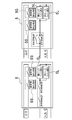
図3Aおよび図3Bは、従来の扉の開閉検知装置と本発明に係る扉の開閉検知装置を対比して示す模式図であり、図3Aは従来の扉の開閉検知装置を示し、図3Bは本発明に係る扉の開閉検知装置を示す。
従来の扉の開閉検知装置においては、図3Aの下側の斜視図に示すように、隣接する左右2枚の扉3,3は、それぞれ逆方向に回転して手前に開く観音開き式になっている。2枚の扉3,3に覆われている部分には、矩形状の開口部31が形成されており、開口部31の上端部には1枚の扉3に対応して1個の扉スイッチ35が設置されている。二つの扉スイッチ35,35は、電線36およびケーブル37を介して互いに接続されている。
図3Aの上側の回路図に示すように、二つの扉スイッチ35,35は、それぞれ開閉可能な接点からなる扉開閉検知部35S,35Sを備えており、各扉3を閉じると各扉開閉検知部35Sの接点が閉じ、各扉3を開くと各扉開閉検知部35Sの接点が開くようになっている。各扉開閉検知部35は、この接点の開閉により扉3の開閉が検知できるようになっている。二つの扉開閉検知部35S,35Sは電線36およびケーブル37を介して互いに接続されている。
従来の扉の開閉検知装置においては、図3Aの下側の斜視図に示すように、隣接する左右2枚の扉3,3は、それぞれ逆方向に回転して手前に開く観音開き式になっている。2枚の扉3,3に覆われている部分には、矩形状の開口部31が形成されており、開口部31の上端部には1枚の扉3に対応して1個の扉スイッチ35が設置されている。二つの扉スイッチ35,35は、電線36およびケーブル37を介して互いに接続されている。
図3Aの上側の回路図に示すように、二つの扉スイッチ35,35は、それぞれ開閉可能な接点からなる扉開閉検知部35S,35Sを備えており、各扉3を閉じると各扉開閉検知部35Sの接点が閉じ、各扉3を開くと各扉開閉検知部35Sの接点が開くようになっている。各扉開閉検知部35は、この接点の開閉により扉3の開閉が検知できるようになっている。二つの扉開閉検知部35S,35Sは電線36およびケーブル37を介して互いに接続されている。
本発明の扉の開閉検知装置においては、図3Bの下側の斜視図に示すように、隣接する左右2枚の扉3,3により覆われている短形状の閉口部31の上端部には、単一の扉スイッチ5が設置されている。扉スイッチ5には電線6が接続されている。
図3Bの上側の回路図に示すように、単一の扉スイッチ5は、開閉可能な接点からなる2以上(図示例では2個)の扉開閉検知部5Sを備えており、2以上の扉開閉検知部5Sは、直列接続回路(図3Bの左側の回路図)になっているか、若しくは並列接続回路(図3Bの右側の回路図)になっている。各扉3を閉じると直列接続回路又は並列接続回路における各扉開閉検知部5Sの接点が閉じ、各扉3を開くと各扉開閉検知部5Sの接点が開くようになっている。扉スイッチ5は、この接点の開閉により扉3の開閉が検知できるようになっている。このように、本発明によれば、扉スイッチ5の内部に、2以上の扉開閉検知部5Sを直列接続若しくは並列接続した回路を設けることにより、一つの扉スイッチ5で2枚以上の扉の開閉検知出力を行うことができる。
図3Bの上側の回路図に示すように、単一の扉スイッチ5は、開閉可能な接点からなる2以上(図示例では2個)の扉開閉検知部5Sを備えており、2以上の扉開閉検知部5Sは、直列接続回路(図3Bの左側の回路図)になっているか、若しくは並列接続回路(図3Bの右側の回路図)になっている。各扉3を閉じると直列接続回路又は並列接続回路における各扉開閉検知部5Sの接点が閉じ、各扉3を開くと各扉開閉検知部5Sの接点が開くようになっている。扉スイッチ5は、この接点の開閉により扉3の開閉が検知できるようになっている。このように、本発明によれば、扉スイッチ5の内部に、2以上の扉開閉検知部5Sを直列接続若しくは並列接続した回路を設けることにより、一つの扉スイッチ5で2枚以上の扉の開閉検知出力を行うことができる。
図4Aおよび図4Bは、従来の電気制御式扉ロック機構と本発明に係る電気制御式扉ロック機構を対比して示す図であり、図4Aは従来の電気制御式扉ロック機構を示す回路図であり、図4Bは本発明に係る電気制御式扉ロック機構を示す回路図である。
従来の電気制御式扉ロック機構においては、図4Aに示すように、扉が2枚の場合、扉開閉検知部35Sを備えた二つの扉スイッチ35,35が設けられていることは、図3Aに示す構成と同様である。図4Aにおいては、二つの扉開閉検知部35Sは、扉開閉検知部Aおよび扉開閉検知部Bと表示して峻別しているが、同一の構成である。そして、各扉開閉検知部35Sに隣接して扉ロックコイル部35Lが設置されている。図4Aにおいては、二つの扉ロックコイル部35Lは、扉ロックコイル部Aおよび扉ロックコイル部Bと表示して峻別しているが、同一の構成である。扉ロックコイル部Aおよび扉ロックコイル部Bには、個別に制御入力(入力1,入力2)を入力し、各扉ロックコイル部における電磁コイルを動作させ、2枚の扉をロックすることができる。このように、従来においては、扉が2枚の場合、電気制御式ロック機構を2つ設置する必要がある。すなわち、制御入力がロック機構の個数分必要となる。
従来の電気制御式扉ロック機構においては、図4Aに示すように、扉が2枚の場合、扉開閉検知部35Sを備えた二つの扉スイッチ35,35が設けられていることは、図3Aに示す構成と同様である。図4Aにおいては、二つの扉開閉検知部35Sは、扉開閉検知部Aおよび扉開閉検知部Bと表示して峻別しているが、同一の構成である。そして、各扉開閉検知部35Sに隣接して扉ロックコイル部35Lが設置されている。図4Aにおいては、二つの扉ロックコイル部35Lは、扉ロックコイル部Aおよび扉ロックコイル部Bと表示して峻別しているが、同一の構成である。扉ロックコイル部Aおよび扉ロックコイル部Bには、個別に制御入力(入力1,入力2)を入力し、各扉ロックコイル部における電磁コイルを動作させ、2枚の扉をロックすることができる。このように、従来においては、扉が2枚の場合、電気制御式ロック機構を2つ設置する必要がある。すなわち、制御入力がロック機構の個数分必要となる。
本発明に係る電気制御式扉ロック機構においては、図4Bに示すように、扉が2枚以上の場合、扉スイッチ5の内部に、2以上の扉開閉検知部5Sを直列接続した回路を設けることは、図3Bに示す構成と同様である。図4Bにおいては、二つの扉開閉検知部5Sは、扉開閉検知部Aおよび扉開閉検知部Bと表示して峻別しているが、同一の構成である。そして、扉開閉検知部5Sに隣接して、単一(図示例では扉ロックコイル部A/Bと表示)の扉ロックコイル部5Lを設けるか(図4Bの上側の回路図)、若しくは2以上(図示例では扉ロックコイル部Aおよび扉ロックコイル部Bと表示された2個)の並列接続された扉ロックコイル部5Lを設けている(図4Bの下側の回路図)。図4Bの上側に示す単一コイル回路の場合、扉ロックコイル部A/Bに1点の制御入力(入力1)を入力し、1個の電磁コイルを動作させ、2枚の扉をロックすることができる。また、図4Bの下側に示す並列コイル接続回路の場合、扉ロックコイル部Aおよび扉ロックコイル部Bに1点の制御入力(入力1)を入力し、2個の電磁コイルを動作させ、2枚の扉をロックすることができる。このように、本発明によれば、電気制御式ロック機構内部へ1点の制御入力で、1個の電磁コイルを動作させ、2枚以上の扉をロックすることができるか、若しくは、1点の制御入力で、並列接続された2個以上の電磁コイルを用いて2枚以上の扉を同時にロックすることができる。
図5Aおよび図5Bは、図4Bの上側に示す単一コイル回路の電気制御式扉ロック機構に好適に用いられるロック機構の機械構造を示す模式図であり、図5Aはロック機構のアンロック状態を示し、図5Bはロック機構のロック状態を示す。
図5Aおよび図5Bにおいて、上側の図はロック機構の部分断面平面図であり、下側の図はロック機構の部分断面側面図である。
図5Aおよび図5Bにおいて、上側の図はロック機構の部分断面平面図であり、下側の図はロック機構の部分断面側面図である。
図5Aおよび図5Bに示すように、扉ロックコイル部における電磁コイル51には、電磁コイルシャフト52が嵌合されている。電磁コイルシャフト52には、電磁コイル51を挟むようにシャフト部より大径の2つのフランジ部52F1,52F2が形成されるとともに、シャフト部より半径方向外側に鉤状に突出した2つのロック用レバー52L1,52L2が形成されている。電磁コイル51とフランジ部52F1との間には圧縮コイルバネ53が介装されている。電磁コイル51には電磁コイル動作入力配線54が接続されている。
一方、2つの扉3(図3B参照)には、それぞれロックキー55A,55Bが固定されている。図3Bにおいて、例えば、ロックキー55Aは左側の扉3に固定されており、ロックキー55Bは右側の扉3に固定されているが、図3Bではロックキー55A,55Bは図示を省略している。また、図5Aおよび図5Bでは、ロックキー55A,55Bのみを示し、扉3の図示を省略している。
一方、2つの扉3(図3B参照)には、それぞれロックキー55A,55Bが固定されている。図3Bにおいて、例えば、ロックキー55Aは左側の扉3に固定されており、ロックキー55Bは右側の扉3に固定されているが、図3Bではロックキー55A,55Bは図示を省略している。また、図5Aおよび図5Bでは、ロックキー55A,55Bのみを示し、扉3の図示を省略している。
次に、図5Aおよび図5Bに示すように構成されたロック機構の動作を説明する。
(1)図5Aに示すアンロック状態
電磁コイル51がOFFのときには、圧縮コイルバネ53の付勢力により、電磁コイルシャフト52は矢印で示すように左側に押され、2つのロック用レバー52L1,52L2はそれぞれロックキー55A,55Bから離間し、ロック機構はアンロック状態となる。
(2)図5Bに示すロック状態
電磁コイル51がONになると、電磁コイル51の吸引力により、電磁コイルシャフト52は矢印で示すように右側に押され、2つのロック用レバー52L1,52L2はそれぞれロックキー55A,55Bの孔部に嵌合される。これにより、ロック機構はロック状態となる。
図5Aおよび図5Bに示すように、電磁コイルが1個の場合、電磁コイルシャフト等を用いた機械構造によって複数のロックを行うことができる。図示例の電磁コイルシャフト形状は、一例であり、引っかかり構造を持つものであればよい。
(1)図5Aに示すアンロック状態
電磁コイル51がOFFのときには、圧縮コイルバネ53の付勢力により、電磁コイルシャフト52は矢印で示すように左側に押され、2つのロック用レバー52L1,52L2はそれぞれロックキー55A,55Bから離間し、ロック機構はアンロック状態となる。
(2)図5Bに示すロック状態
電磁コイル51がONになると、電磁コイル51の吸引力により、電磁コイルシャフト52は矢印で示すように右側に押され、2つのロック用レバー52L1,52L2はそれぞれロックキー55A,55Bの孔部に嵌合される。これにより、ロック機構はロック状態となる。
図5Aおよび図5Bに示すように、電磁コイルが1個の場合、電磁コイルシャフト等を用いた機械構造によって複数のロックを行うことができる。図示例の電磁コイルシャフト形状は、一例であり、引っかかり構造を持つものであればよい。
図6A,図6Bおよび図6Cは、図4Aに示す従来の電気制御式扉ロック機構と図4Bに示す本発明に係る電気制御式扉ロック機構に動作条件を作る回路を加えた回路図であり、図6Aは従来の電気制御式扉ロック機構を示す回路図であり、図6Bおよび図6Cは本発明に係る電気制御式扉ロック機構を示す回路図である。
従来の電気制御式扉ロック機構においては、図6Aに示すように、図4Aに示す扉ロックコイル部Aおよび扉ロックコイル部Bの入力側の外部回路に、それぞれリレー38を設置している。このように、扉スイッチ35の外部回路としてリレー38を設置し、扉開閉条件に応じてリレー38を動作させ、扉ロックコイル部Aおよび扉ロックコイル部Bに個別に制御入力(入力1,入力2)を入力し、各扉ロックコイル部における電磁コイルを動作させ、2枚の扉をロックすることができる。
従来の電気制御式扉ロック機構においては、図6Aに示すように、図4Aに示す扉ロックコイル部Aおよび扉ロックコイル部Bの入力側の外部回路に、それぞれリレー38を設置している。このように、扉スイッチ35の外部回路としてリレー38を設置し、扉開閉条件に応じてリレー38を動作させ、扉ロックコイル部Aおよび扉ロックコイル部Bに個別に制御入力(入力1,入力2)を入力し、各扉ロックコイル部における電磁コイルを動作させ、2枚の扉をロックすることができる。
本発明に係る電気制御式扉ロック機構においては、図6Bに示す第1の態様では、図4Bに示す扉ロックコイル部A/Bの入力側の内部回路に、扉開閉検知部接点Aおよび扉開閉検知部接点Bを直列接続(図6Bの左側の図)又は並列接続(図6Bの右側の図)で設け、扉開閉条件に応じた扉ロック動作を行うように構成している。
図6Cに示す第2の態様では、図4Bに示す扉ロックコイル部Aおよび扉ロックコイル部Bの入力側の内部回路に、扉開閉検知部接点Aおよび扉開閉検知部接点Bを直列接続(図6Cの左側の図)又は並列接続(図6Cの右側の図)で設け、扉開閉条件に応じた扉ロック動作を行うように構成している。図6Bおよび図6Cにおいて、扉開閉検知部接点A,Bを電磁コイル2次側に設けてもよい。
図6Bおよび図6Cに示すように、本発明に係る電気制御式扉ロック機構によれば、電気制御式ロック機構へ扉ロック指令入力する場合、ロック用電磁コイル回路の1次側若しくは2次側へ扉開閉検知出力回路の接点を入れることで、内部回路のみで、扉開閉条件に応じた扉ロック動作を行うことができる。
これまで本発明の実施形態について説明したが、本発明は上述の実施形態に限定されず、その技術思想の範囲内において、種々の異なる形態で実施されてよいことは勿論である。
本発明は、各種機器のハウジング、内部に所定の空間を形成する筐体、空間を仕切る仕切り壁等に設けられている扉の開閉を検知及びロックする検知装置に利用可能である。
1 ハウジング
2 ロード/アンロード部
3 扉
5,35 扉スイッチ
5S,35S 扉開閉検知部
6,36 電線
31 開口部
35L 扉ロックコイル部
37 ケーブル
38 リレー
51 電磁コイル
52L1,52L2 ロック用レバー
52 電磁コイルシャフト
53 圧縮コイルバネ
55A,55B ロックキー
2 ロード/アンロード部
3 扉
5,35 扉スイッチ
5S,35S 扉開閉検知部
6,36 電線
31 開口部
35L 扉ロックコイル部
37 ケーブル
38 リレー
51 電磁コイル
52L1,52L2 ロック用レバー
52 電磁コイルシャフト
53 圧縮コイルバネ
55A,55B ロックキー
Claims (6)
- 開口部に設置された2枚以上の扉の開閉を検知する扉の開閉検知装置であって、
前記2枚以上の扉に共通の単一の扉スイッチを設け、
前記扉スイッチは、前記2枚以上の扉の各々に対応して2以上の扉開閉検知部を備え、前記2以上の扉開閉検知部の出力回路は前記扉スイッチ内で直列接続又は並列接続されていることを特徴とする扉の開閉検知装置。 - 前記扉スイッチは、単一の制御入力で1個の電磁コイルを動作させて前記2以上の扉をロックする扉ロックコイル部を備えたことを特徴とする請求項1記載の扉の開閉検知装置。
- 前記扉ロックコイル部は、前記1個の電磁コイルと、前記電磁コイルの動作により移動する電磁コイルシャフトを備え、前記電磁コイルシャフトは、前記電磁コイルの動作により前記2枚以上の扉にそれぞれ固定されたロックキーに係合する2以上のロック用レバーを備えたことを特徴とする請求項2記載の扉の開閉検知装置。
- 前記扉スイッチは、単一の制御入力で並列接続された2個以上の電磁コイルを動作させて前記2以上の扉をロックする扉ロックコイル部を備えたことを特徴とする請求項1記載の扉の開閉検知装置。
- 前記扉スイッチは、前記扉ロックコイル部の1次側若しくは2次側に、前記扉開閉検知部の出力回路の接点を備えることを特徴とする請求項2乃至4のいずれか1項に記載の扉の開閉検知装置。
- 前記2以上の扉開閉検知部の出力回路の接点は、直列接続又は並列接続されていることを特徴とする請求項5記載の扉の開閉検知装置。
Applications Claiming Priority (2)
| Application Number | Priority Date | Filing Date | Title |
|---|---|---|---|
| JP2015-000989 | 2015-01-06 | ||
| JP2015000989A JP6566640B2 (ja) | 2015-01-06 | 2015-01-06 | 基板研磨装置 |
Publications (1)
| Publication Number | Publication Date |
|---|---|
| WO2016111141A1 true WO2016111141A1 (ja) | 2016-07-14 |
Family
ID=56355843
Family Applications (1)
| Application Number | Title | Priority Date | Filing Date |
|---|---|---|---|
| PCT/JP2015/085512 Ceased WO2016111141A1 (ja) | 2015-01-06 | 2015-12-18 | 扉の開閉検知装置 |
Country Status (2)
| Country | Link |
|---|---|
| JP (1) | JP6566640B2 (ja) |
| WO (1) | WO2016111141A1 (ja) |
Cited By (1)
| Publication number | Priority date | Publication date | Assignee | Title |
|---|---|---|---|---|
| CN111515871A (zh) * | 2020-05-09 | 2020-08-11 | 湖北华磁电子科技有限公司 | 一种软磁铁氧体磁芯表面打磨装置 |
Families Citing this family (4)
| Publication number | Priority date | Publication date | Assignee | Title |
|---|---|---|---|---|
| JP7184453B2 (ja) * | 2018-05-17 | 2022-12-06 | 株式会社ディスコ | 搬送システム |
| JP2020067002A (ja) * | 2018-10-22 | 2020-04-30 | 株式会社不二工機 | 可変容量型圧縮機用制御弁 |
| JP7109863B2 (ja) * | 2018-11-30 | 2022-08-01 | 株式会社ディスコ | 搬送システム |
| JP7774846B2 (ja) * | 2021-11-10 | 2025-11-25 | 株式会社タカゾノ | 薬剤供給装置 |
Citations (1)
| Publication number | Priority date | Publication date | Assignee | Title |
|---|---|---|---|---|
| JPH0473185U (ja) * | 1990-11-08 | 1992-06-26 |
Family Cites Families (6)
| Publication number | Priority date | Publication date | Assignee | Title |
|---|---|---|---|---|
| US4673914A (en) * | 1984-03-20 | 1987-06-16 | Lee Ki Chang | Keyless automobile door lock/unlock, ignition switching and burglar alarm system |
| JPH0637511Y2 (ja) * | 1989-09-29 | 1994-09-28 | 三菱自動車エンジニアリング株式会社 | 扉の開閉検出装置 |
| JP3052184B2 (ja) * | 1995-07-19 | 2000-06-12 | スガツネ工業株式会社 | 開閉部材の感震自動ロック装置 |
| JP2003011668A (ja) * | 2001-06-29 | 2003-01-15 | Fujikura Ltd | 自動車用ドアの開閉検知装置 |
| JP2004232352A (ja) * | 2003-01-30 | 2004-08-19 | Alpha Corp | 箱錠制御装置 |
| JP5368651B1 (ja) * | 2013-04-23 | 2013-12-18 | 正人 福島 | 施錠装置及び侵入防止装置 |
-
2015
- 2015-01-06 JP JP2015000989A patent/JP6566640B2/ja active Active
- 2015-12-18 WO PCT/JP2015/085512 patent/WO2016111141A1/ja not_active Ceased
Patent Citations (1)
| Publication number | Priority date | Publication date | Assignee | Title |
|---|---|---|---|---|
| JPH0473185U (ja) * | 1990-11-08 | 1992-06-26 |
Cited By (1)
| Publication number | Priority date | Publication date | Assignee | Title |
|---|---|---|---|---|
| CN111515871A (zh) * | 2020-05-09 | 2020-08-11 | 湖北华磁电子科技有限公司 | 一种软磁铁氧体磁芯表面打磨装置 |
Also Published As
| Publication number | Publication date |
|---|---|
| JP6566640B2 (ja) | 2019-08-28 |
| JP2016125292A (ja) | 2016-07-11 |
Similar Documents
| Publication | Publication Date | Title |
|---|---|---|
| JP6566640B2 (ja) | 基板研磨装置 | |
| CN110770988B (zh) | 包含无人操作和维护的开关装置或控制装置的变电站 | |
| US9239228B2 (en) | Wafer mapping apparatus and load port including same | |
| CN110832720B (zh) | 包含无人操作和维护的开关装置或控制装置的变电站 | |
| US7973253B2 (en) | Neutral draw-out automatic transfer switch assembly and associated method | |
| CN102591818A (zh) | 用于耦合输入/输出设备的系统与方法 | |
| CN108701584B (zh) | 基板处理装置 | |
| KR20200021538A (ko) | 이송 장치 및 어댑터 펜던트 | |
| US11623843B2 (en) | Elevator inspection operation device | |
| US20130175908A1 (en) | Wafer Stocker | |
| EP3196912B1 (en) | Switch | |
| CN218512830U (zh) | 一种应用于晶圆加工设备的安全控制系统 | |
| KR102586784B1 (ko) | 반송 검지 방법 및 기판 처리 장치 | |
| CN115685855A (zh) | 一种应用于晶圆加工设备的安全控制系统 | |
| JP7336707B2 (ja) | 安全スイッチ及びスイッチシステム | |
| CN109416986B (zh) | 用于电气装备的断路器的远程操作的补充隔离设备 | |
| WO2018019639A1 (en) | Hoistway door lock with reed switches | |
| US20200208442A1 (en) | Mechanical lockout for non-mechanical-interfacing electronic switch | |
| JP2008226604A (ja) | 押しボタンスイッチ | |
| KR102538920B1 (ko) | 라인 시스템 | |
| KR20150008724A (ko) | 기판 처리 장치 및 방법 | |
| US12347638B2 (en) | Mechanical lockout for solid-state switch | |
| KR102669106B1 (ko) | 독립 모듈형 셀 구조를 갖는 프로버 | |
| CN108475593A (zh) | 用于断开接触器的断路器设备和装置 | |
| US20250054796A1 (en) | Integrated load port first aid platform |
Legal Events
| Date | Code | Title | Description |
|---|---|---|---|
| 121 | Ep: the epo has been informed by wipo that ep was designated in this application |
Ref document number: 15877014 Country of ref document: EP Kind code of ref document: A1 |
|
| NENP | Non-entry into the national phase |
Ref country code: DE |
|
| 122 | Ep: pct application non-entry in european phase |
Ref document number: 15877014 Country of ref document: EP Kind code of ref document: A1 |