WO2016117172A1 - 排ガス処理システム及び方法 - Google Patents
排ガス処理システム及び方法 Download PDFInfo
- Publication number
- WO2016117172A1 WO2016117172A1 PCT/JP2015/076954 JP2015076954W WO2016117172A1 WO 2016117172 A1 WO2016117172 A1 WO 2016117172A1 JP 2015076954 W JP2015076954 W JP 2015076954W WO 2016117172 A1 WO2016117172 A1 WO 2016117172A1
- Authority
- WO
- WIPO (PCT)
- Prior art keywords
- mist
- exhaust gas
- absorbing
- collecting
- treatment system
- Prior art date
- Legal status (The legal status is an assumption and is not a legal conclusion. Google has not performed a legal analysis and makes no representation as to the accuracy of the status listed.)
- Ceased
Links
Images


Classifications
-
- B—PERFORMING OPERATIONS; TRANSPORTING
- B01—PHYSICAL OR CHEMICAL PROCESSES OR APPARATUS IN GENERAL
- B01D—SEPARATION
- B01D53/00—Separation of gases or vapours; Recovering vapours of volatile solvents from gases; Chemical or biological purification of waste gases, e.g. engine exhaust gases, smoke, fumes, flue gases, aerosols
- B01D53/14—Separation of gases or vapours; Recovering vapours of volatile solvents from gases; Chemical or biological purification of waste gases, e.g. engine exhaust gases, smoke, fumes, flue gases, aerosols by absorption
-
- B—PERFORMING OPERATIONS; TRANSPORTING
- B01—PHYSICAL OR CHEMICAL PROCESSES OR APPARATUS IN GENERAL
- B01D—SEPARATION
- B01D53/00—Separation of gases or vapours; Recovering vapours of volatile solvents from gases; Chemical or biological purification of waste gases, e.g. engine exhaust gases, smoke, fumes, flue gases, aerosols
- B01D53/14—Separation of gases or vapours; Recovering vapours of volatile solvents from gases; Chemical or biological purification of waste gases, e.g. engine exhaust gases, smoke, fumes, flue gases, aerosols by absorption
- B01D53/1456—Removing acid components
- B01D53/1475—Removing carbon dioxide
-
- B—PERFORMING OPERATIONS; TRANSPORTING
- B01—PHYSICAL OR CHEMICAL PROCESSES OR APPARATUS IN GENERAL
- B01D—SEPARATION
- B01D53/00—Separation of gases or vapours; Recovering vapours of volatile solvents from gases; Chemical or biological purification of waste gases, e.g. engine exhaust gases, smoke, fumes, flue gases, aerosols
- B01D53/14—Separation of gases or vapours; Recovering vapours of volatile solvents from gases; Chemical or biological purification of waste gases, e.g. engine exhaust gases, smoke, fumes, flue gases, aerosols by absorption
- B01D53/18—Absorbing units; Liquid distributors therefor
-
- B—PERFORMING OPERATIONS; TRANSPORTING
- B01—PHYSICAL OR CHEMICAL PROCESSES OR APPARATUS IN GENERAL
- B01D—SEPARATION
- B01D53/00—Separation of gases or vapours; Recovering vapours of volatile solvents from gases; Chemical or biological purification of waste gases, e.g. engine exhaust gases, smoke, fumes, flue gases, aerosols
- B01D53/34—Chemical or biological purification of waste gases
- B01D53/46—Removing components of defined structure
- B01D53/48—Sulfur compounds
- B01D53/50—Sulfur oxides
-
- B—PERFORMING OPERATIONS; TRANSPORTING
- B01—PHYSICAL OR CHEMICAL PROCESSES OR APPARATUS IN GENERAL
- B01D—SEPARATION
- B01D53/00—Separation of gases or vapours; Recovering vapours of volatile solvents from gases; Chemical or biological purification of waste gases, e.g. engine exhaust gases, smoke, fumes, flue gases, aerosols
- B01D53/34—Chemical or biological purification of waste gases
- B01D53/46—Removing components of defined structure
- B01D53/48—Sulfur compounds
- B01D53/50—Sulfur oxides
- B01D53/501—Sulfur oxides by treating the gases with a solution or a suspension of an alkali or earth-alkali or ammonium compound
- B01D53/504—Sulfur oxides by treating the gases with a solution or a suspension of an alkali or earth-alkali or ammonium compound characterised by a specific device
-
- B—PERFORMING OPERATIONS; TRANSPORTING
- B01—PHYSICAL OR CHEMICAL PROCESSES OR APPARATUS IN GENERAL
- B01D—SEPARATION
- B01D53/00—Separation of gases or vapours; Recovering vapours of volatile solvents from gases; Chemical or biological purification of waste gases, e.g. engine exhaust gases, smoke, fumes, flue gases, aerosols
- B01D53/34—Chemical or biological purification of waste gases
- B01D53/46—Removing components of defined structure
- B01D53/62—Carbon oxides
-
- B—PERFORMING OPERATIONS; TRANSPORTING
- B01—PHYSICAL OR CHEMICAL PROCESSES OR APPARATUS IN GENERAL
- B01D—SEPARATION
- B01D53/00—Separation of gases or vapours; Recovering vapours of volatile solvents from gases; Chemical or biological purification of waste gases, e.g. engine exhaust gases, smoke, fumes, flue gases, aerosols
- B01D53/34—Chemical or biological purification of waste gases
- B01D53/74—General processes for purification of waste gases; Apparatus or devices specially adapted therefor
- B01D53/75—Multi-step processes
-
- C—CHEMISTRY; METALLURGY
- C01—INORGANIC CHEMISTRY
- C01B—NON-METALLIC ELEMENTS; COMPOUNDS THEREOF; METALLOIDS OR COMPOUNDS THEREOF NOT COVERED BY SUBCLASS C01C
- C01B32/00—Carbon; Compounds thereof
- C01B32/50—Carbon dioxide
-
- F—MECHANICAL ENGINEERING; LIGHTING; HEATING; WEAPONS; BLASTING
- F23—COMBUSTION APPARATUS; COMBUSTION PROCESSES
- F23J—REMOVAL OR TREATMENT OF COMBUSTION PRODUCTS OR COMBUSTION RESIDUES; FLUES
- F23J15/00—Arrangements of devices for treating smoke or fumes
-
- B—PERFORMING OPERATIONS; TRANSPORTING
- B01—PHYSICAL OR CHEMICAL PROCESSES OR APPARATUS IN GENERAL
- B01D—SEPARATION
- B01D2252/00—Absorbents, i.e. solvents and liquid materials for gas absorption
- B01D2252/20—Organic absorbents
- B01D2252/204—Amines
-
- B—PERFORMING OPERATIONS; TRANSPORTING
- B01—PHYSICAL OR CHEMICAL PROCESSES OR APPARATUS IN GENERAL
- B01D—SEPARATION
- B01D2258/00—Sources of waste gases
- B01D2258/02—Other waste gases
- B01D2258/0283—Flue gases
-
- Y—GENERAL TAGGING OF NEW TECHNOLOGICAL DEVELOPMENTS; GENERAL TAGGING OF CROSS-SECTIONAL TECHNOLOGIES SPANNING OVER SEVERAL SECTIONS OF THE IPC; TECHNICAL SUBJECTS COVERED BY FORMER USPC CROSS-REFERENCE ART COLLECTIONS [XRACs] AND DIGESTS
- Y02—TECHNOLOGIES OR APPLICATIONS FOR MITIGATION OR ADAPTATION AGAINST CLIMATE CHANGE
- Y02C—CAPTURE, STORAGE, SEQUESTRATION OR DISPOSAL OF GREENHOUSE GASES [GHG]
- Y02C20/00—Capture or disposal of greenhouse gases
- Y02C20/40—Capture or disposal of greenhouse gases of CO2
-
- Y—GENERAL TAGGING OF NEW TECHNOLOGICAL DEVELOPMENTS; GENERAL TAGGING OF CROSS-SECTIONAL TECHNOLOGIES SPANNING OVER SEVERAL SECTIONS OF THE IPC; TECHNICAL SUBJECTS COVERED BY FORMER USPC CROSS-REFERENCE ART COLLECTIONS [XRACs] AND DIGESTS
- Y02—TECHNOLOGIES OR APPLICATIONS FOR MITIGATION OR ADAPTATION AGAINST CLIMATE CHANGE
- Y02E—REDUCTION OF GREENHOUSE GAS [GHG] EMISSIONS, RELATED TO ENERGY GENERATION, TRANSMISSION OR DISTRIBUTION
- Y02E20/00—Combustion technologies with mitigation potential
- Y02E20/32—Direct CO2 mitigation
Definitions
- the present invention relates to an exhaust gas treatment system and method that significantly suppresses the emission of amine absorbing liquid out of the system when absorbing and removing CO 2 in the exhaust gas with the amine absorbing liquid.
- CO 2 absorption tower (hereinafter, simply referred to as "absorption column”.) Flue gas in a CO 2 absorption a step of contacting a liquid, the CO 2 absorbent that has absorbed CO 2 CO 2 absorbing solution regeneration tower (hereinafter, simply referred to as "regeneration tower”.) was heated in, along with dissipating CO 2, CO 2 absorption There has been proposed a CO 2 recovery device having a step of regenerating the liquid and circulating it again to the CO 2 absorption tower for reuse (see, for example, Patent Document 1).
- CO 2 absorption tower for example, an amine-based CO 2 absorbing solution such as alkanolamine is used for countercurrent contact, and CO 2 in the exhaust gas is absorbed into the CO 2 absorbing solution by a chemical reaction (exothermic reaction), and CO 2 The exhaust gas from which is removed is discharged out of the system.
- CO 2 absorbent that has absorbed CO 2 is referred to as rich solution.
- the rich solution is pressurized by the pump, the CO 2 absorbing solution in a high temperature CO 2 in the regeneration tower has been regenerated dissipation (lean solution), heated in the heat exchanger, is supplied to the regenerator.
- CO 2 -removed exhaust gas obtained by removing CO 2 from the combustion exhaust gas is released to the atmosphere, but there is a very small part of the amine absorbent in the released gas. It is necessary to reduce the amount of emissions.
- the CO 2 removal equipment itself may be increased in size, and further emission reduction is required.
- Patent Document 2 A method for recovering an amine compound entrained in a CO 2 -removed exhaust gas has been proposed (Patent Document 2).
- Patent Document 3 sulfuric acid is sprayed from a sulfuric acid spray device to the CO 2 removal exhaust gas discharged from the CO 2 absorption tower, and the amine absorption liquid accompanying the exhaust gas is changed to a basic amine compound sulfate, and the base A method of recovering a basic amine compound in a decarbonation tower exhaust gas for collecting a basic amine compound sulfate has been proposed (Patent Document 3).
- the exhaust gas treatment system the flue gas introduced into the CO 2 absorber that absorbs CO 2 of the CO 2 recovery apparatus, the mist generating material which is a source of mist generated in the absorption tower of the CO 2 recovery apparatus If included, the CO 2 absorbing solution is entrained by the mist generating substance, so that there is a problem that the amount of the CO 2 absorbing solution scattered outside the system increases. 4).
- the gaseous amine absorption liquid can be reduced in the CO 2 removal exhaust gas discharged from the CO 2 absorption tower, the mist-like amine absorption liquid may be released together with the exhaust gas. It is necessary to suppress this.
- the present invention provides an exhaust gas treatment system and method that can significantly suppress entrainment of a CO 2 absorbent when exhausting treated exhaust gas from which CO 2 has been removed to the outside of the system.
- a first invention of the present invention for solving the above-mentioned problems is a desulfurization device for removing sulfur oxides in exhaust gas from a boiler, and a mist provided on the downstream side of the desulfurization device and contained in the exhaust gas.
- a mist collecting and aggregating device that binds each other to enlarge the particle size to form an agglomerated mist, and a CO 2 absorption part that removes CO 2 contained in the exhaust gas by contacting the CO 2 absorbing solution and the CO 2 absorber having, together with releasing the CO 2 recovering CO 2 from the CO 2 absorbent having absorbed the CO 2, and CO 2 recovery apparatus comprising a absorbent regenerator to regenerate the CO 2 absorbing solution the CO 2 provided in the gas flow downstream side of the absorption unit, collecting the CO 2 absorbing portion in the aggregating and enlarging mist to the CO 2 absorbing solution CO 2 absorbing solution enlarged mist bloated is absorbed And a mist collecting section In the exhaust gas treatment system.
- the second invention is the exhaust gas treatment system according to the first invention, wherein a flow rate of the exhaust gas in the mist collecting / aggregating device exceeds a limit filtration wind speed of mist collection.
- a water washing unit is provided between the CO 2 absorbing unit and the mist collecting unit.
- a fourth invention is the exhaust gas treatment system according to any one of the first to third aspects, wherein the mist collecting / aggregating device enlarges the mist with a wire mesh.
- the fifth invention is the exhaust gas treatment system according to any one of the first to third inventions, wherein the mist collecting / aggregating device enlarges the mist by charging.
- the mist contained in the exhaust gas from the wet desulfurization apparatus that removes sulfur oxides in the exhaust gas from the boiler is combined to enlarge the particle size to obtain an agglomerated enlarged mist.
- the CO 2 absorption liquid gas flow downstream side is introduced into the CO 2 absorbing portion for removing CO 2
- the CO 2 contained in the flue gas CO 2 absorbing solution when removing in contact with the aggregated bloated mist is absorbed CO 2 absorbing liquid and bloated CO 2 absorbing solution bloated mist collecting the CO 2 absorbing solution hypertrophy mist mist collecting unit
- the exhaust gas treatment method is characterized by the following.
- the seventh invention is the exhaust gas treatment method according to the sixth invention, characterized in that the flow rate of the exhaust gas for re-scattering the agglomerated enlarged mist exceeds the limit filtration wind speed of mist collection.
- the mist contained in the exhaust gas from the desulfurization device is combined with the mist collecting / aggregating device to enlarge the particle size to obtain an agglomerated enlarged mist, and the agglomerated enlarged mist is re-scattered.
- the aggregating and enlarging mist was a CO 2 absorbing solution enlarged mist CO 2 absorbing liquid bloated are absorbed as a nucleus, the The CO 2 absorbing liquid enlarged mist can be collected by the mist collecting section.
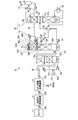
- FIG. 1 is a schematic diagram of an exhaust gas treatment system according to a first embodiment.
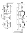
- FIG. 2-1 is a schematic diagram showing the mechanism of mist enlargement according to the present invention.
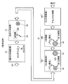
- FIG. 2-2 is a schematic diagram showing the mechanism of mist enlargement according to the prior art.
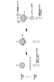
- FIG. 3 is a schematic diagram of mist enlargement according to the present invention.
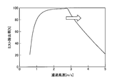
- FIG. 4 is a diagram illustrating an example of the relationship between the filtration wind speed and the mist removal rate.
- FIG. 5 is a diagram illustrating an example of the relationship between the filtration wind speed, the mist adhesion rate, and the mist re-scattering rate.
- FIG. 6 is a schematic diagram of mist enlargement due to electrification.
- Figure 7 is a relational diagram of the SO 3 mist concentration at the inlet in the exhaust gas of the CO 2 absorbing section, the released gas in the amine concentration of the mist collecting portion outlet of the CO 2 absorber.
- FIG. 1 is a schematic diagram of an exhaust gas treatment system according to a first embodiment. As shown in FIG. 1, the exhaust gas treatment system 10 according to the present embodiment is provided on the downstream side of a wet desulfurization device 13 that removes sulfur oxide in the exhaust gas 12A from the boiler 11 and the desulfurization device 13.
- a mist collecting and aggregating device 14 which is an agglomerated SO 3 mist 51 which is an agglomerated enlarged mist obtained by combining SO 3 mists 50 contained in the exhaust gas 12B from the wet desulfurization device 13 to enlarge the particle size; a flue gas cooler 15 for cooling the exhaust gases 12C from mist collecting-agglomerator 14, the CO 2 absorbing section 16A to be removed by contacting the CO 2 contained in flue gas 12D from flue gas cooler 15 to the CO 2 absorbing solution and the CO 2 absorber 16 having, this CO 2 from the CO 2 absorbent having absorbed by releasing CO 2 consists absorbent regenerator 17 for regeneration of CO 2 absorbing solution with the recovery of CO 2 CO 2 recovery Dress 18, provided in the gas flow downstream side of the CO 2 absorbing section 16A, and the water washing section 16B for washing the exhaust 12E, provided in the gas flow downstream side of the washing unit 16B, the CO 2 absorbing section 16A and washing unit 16B And a mist collecting section 16C for collecting the CO
- mist SO 3 mist 50, agglomerated SO 3 mist 51, CO 2 absorbing liquid enlarged mist 53
- SO 3 mist is used as an example of mist in the present embodiment
- the present invention is not limited to this.
- fine mist generated by moisture adhering to solid particles such as fine coal ash, etc. It can be illustrated.
- CO 2 in the combustion exhaust gas is illustrated as an object to be removed.
- FIG. 1 only the main equipment is shown, and the attached equipment is omitted.
- reference numeral 12G is purified exhaust gas
- 16D is a de-CO 2 combustion exhaust gas discharge port
- 16E is an absorption liquid supply port
- 16F is a liquid distributor
- 15a is a cooling water liquid distributor
- 15b is a cooling water circulation pump
- 15c is replenishment.
- the exhaust gas 12A from the boiler 11 is removed from the sulfur oxide in the exhaust gas 12A by the wet desulfurization device 13, and the exhaust gas 12B from the desulfurization device 13 is introduced into the mist collection / aggregation device 14, where The SO 3 mists are agglomerated and enlarged to form an agglomerated SO 3 mist. Thereafter, the exhaust gas 12C containing the agglomerated SO 3 mist is pushed into the exhaust gas cooling tower 15 by the combustion exhaust gas supply blower 30, and is cooled by contact with the cooling water from the cooling water liquid distributor 15a and the filling portion 15e.
- the cooled exhaust gas 12 ⁇ / b > D is guided into the CO 2 absorption tower 16 through the combustion exhaust gas supply port 16 a of the CO 2 absorption tower 16.
- the cooling water that has come into contact with the exhaust gas 12C accumulates in the lower part of the combustion exhaust gas cooler 15, and is circulated and used by the cooling water circulation pump 15b to the cooling water liquid distributor 15a.
- the cooling water is replenished by the makeup water supply line 15c.
- the amount of moisture in the exhaust gas 12B is large, moisture in the combustion exhaust gas is condensed by contact with the cooling water and the amount of cooling water is increased, so that excess drainage is discharged through the drainage discharge line 15d.
- the exhaust gas 12D pushed into the CO 2 absorption tower 16 is brought into countercurrent contact with a constant concentration of CO 2 absorption liquid supplied from the liquid disperser 16F at the filling portion in the CO 2 absorption portion 16A.
- CO 2 in is absorbed and removed in the absorbent liquid, removing CO 2 by exhaust gas. 12E toward the water washing section 16B of the gas flow downstream side.
- the absorption liquid supplied to the CO 2 absorption tower 16 absorbs CO 2, and due to the reaction heat due to the absorption, the absorption liquid discharge pump 21 which normally has a temperature higher than the temperature at the combustion exhaust gas supply port 16a and has absorbed CO 2.
- the temperature of the regenerated absorbent can be adjusted by the heat exchanger 22 or, if necessary, the cooler 31 provided between the heat exchanger 22 and the absorbent supply port 16E.
- the absorption liquid is regenerated in the lower filling portion 17 b by heating by the regeneration heater (reboiler) 32, cooled by the heat exchanger 22, and returned to the CO 2 absorption tower 16 side.
- the CO 2 separated from the absorption liquid comes into contact with the reflux water supplied from the nozzle 28 at the upper filling section 23, is cooled by the regeneration tower reflux cooler 27, and is separated into the CO 2 separator 25. Then, the water vapor accompanying the CO 2 is separated from the condensed reflux water and led to the CO 2 recovery process from the recovered CO 2 discharge line 26.
- a part of the reflux water is refluxed to the absorption liquid regeneration tower 17 by the reflux water pump 24, and a part is supplied to the regeneration tower reflux water supply port 29 a of the CO 2 absorption tower 16 through the regeneration tower reflux water supply line 29. . Since the absorption liquid contained in this regenerated reflux water is very small, it comes into contact with the exhaust gas at the water washing section 16B of the CO 2 absorption tower 16 and contributes to the recovery of the trace amount of absorbent contained in the de-CO 2 combustion exhaust gas 12E. To do.
- FIG. 2-1 is a schematic diagram showing the mechanism of mist enlargement according to the present invention.
- FIG. 2-2 is a schematic diagram showing the mechanism of mist enlargement according to the prior art.
- the exhaust gas 12A from the boiler 11 introduced into the wet desulfurization apparatus 13 generates SO 3 mist 50 from a part of the SO 3 gas in the desulfurization apparatus 13.
- the generated SO 3 mist 50 is included in the exhaust gas 12B discharged from the desulfurization apparatus 13.
- the SO 3 mist 50 in the exhaust gas 12B introduced into the mist collecting / aggregating device 14 provided on the downstream side of the desulfurization device 13 adheres to, for example, a wire mesh and agglomerates to enlarge the agglomerated SO 3 mist 51. It becomes.
- the exhaust gas 12 ⁇ / b> C containing the aggregated SO 3 mist 51 enlarged in the mist collection / aggregation apparatus 14 is then introduced into the exhaust gas cooling tower 15.
- the aggregated SO 3 mist 51 absorbs the water vapor 60 in the exhaust gas cooling tower 15 and becomes diluted sulfuric acid, and becomes diluted sulfuric acid mist 52 having the aggregated SO 3 mist 51 as a nucleus.
- the exhaust gas 12D containing the dilute sulfuric acid mist 52 having the aggregated SO 3 mist 51 enlarged in the exhaust gas cooling tower 15 as a nucleus is then introduced into the CO 2 absorption section 16A in the CO 2 absorption tower 16.
- the dilute sulfuric acid mist 52 having the aggregated SO 3 mist 51 in the exhaust gas introduced into the CO 2 absorbing portion 16A as a nucleus uses the water vapor 60 in the CO 2 absorbing portion 16A and the amine compound as the CO 2 absorbing liquid. Then, the amine vapor 61 is absorbed, and an enlarged CO 2 absorbent liquid enlarged mist 53 containing a high concentration of amine is obtained.
- the exhaust gas 12E containing the CO 2 absorbing liquid enlarged mist 53 enlarged in the CO 2 absorbing portion 16A is then introduced into the water washing portion 16B.
- the water vapor 60 and the amine vapor 61 in the water washing section 16B are further absorbed to become an enlarged CO 2 absorbing liquid enlarged mist 53 containing a high concentration of amine.
- a demister provided with a wire mesh is used, and the CO 2 absorbing liquid enlarged mist 53 enlarged is collected in this demister.
- the mist collecting and aggregating apparatus 14 as in the present embodiment is not provided, so that the nucleus for forming the diluted sulfuric acid mist in the exhaust gas cooling tower 15 is formed.
- the size of is small.
- the CO 2 absorption liquid enlargement mist 53 is smaller than in the case of the present invention.
- the mist collecting section 16C on the outlet side in the CO 2 absorption tower 16 the collection efficiency of the CO 2 absorbing liquid enlarged mist 53 enlarged to a demister equipped with a wire mesh is low.
- Table 1 below shows the outlet mist particle size of the desulfurization device 13 in the prior art and Example 1, the outlet mist particle size of the mist collecting / aggregating device 14, and the inlet mist particle size of the mist collecting portion 16C.
- the SO 2 mist 50 particle size 0.1 to 1.0 ⁇ m
- the CO 2 absorption portion 16A The mist particle size at the inlet of the mist collecting section 16C was 0.5 to 2.0 ⁇ m.
- the mist collecting / aggregating device 14 since the mist collecting / aggregating device 14 is installed, for example, when two mists having an outlet mist particle size of 0.1 to 1.0 ⁇ m of the desulfurization device 13 aggregate.
- the mist particle size at the outlet of the mist collecting / aggregating device 14 is enlarged to 0.12 to 1.2 ⁇ m.
- the agglomerated SO 3 mist 51 obtained by agglomerating the two mists serves as a nucleus and is introduced into the CO 2 absorbing portion 16A, where it is enlarged and the inlet mist particle size of the mist collecting portion 16C is 0.6-2. It was 3 ⁇ m.
- the outlet mist particle size of the mist collection / aggregation device 14 is 0.17 to 1.7 ⁇ m and enlarged.
- the agglomerated SO 3 mist 51 formed by agglomeration of the five mists serves as a nucleus and is introduced into the CO 2 absorbing part 16A, where it is enlarged and the inlet mist particle size of the mist collecting part 16C is 0.7-2. It was 9 ⁇ m.
- Example 1 As a result, according to Example 1, it was possible to improve the collection efficiency in the mist collection unit 16C.
- the removing means using the wire mesh is selected as the mist collecting / aggregating device 14 .
- a mist removing device using a fine filter cloth such as a candle filter using the Brown diffusion principle is suitable for removing fine mist of several ⁇ m or less. Since it is necessary to operate at a low temperature and the apparatus becomes large, it is not preferable.
- a corrugated plate type mist removing device when used, it is possible to reduce the size of the device because the filtration wind speed can be increased. However, since the inertia force proportional to the mass is small for fine particles, the mist removing efficiency is low. descend. For this reason, it is not practically preferable to use a corrugated mist removing device for removing fine particles. Therefore, a removing means using a wire mesh is preferable as the mist collecting / aggregating device 14.
- FIG. 3 is a schematic diagram of mist enlargement according to the present invention.
- the lower side of the paper surface is the downstream side of the gas flow
- the upper side of the paper surface is the upstream side of the gas flow.
- the SO 3 mist 50 adhering to the surface of the wire mesh 70 agglomerates in contact with each other to become the aggregated SO 3 mist 51.
- the agglomerated SO 3 mist 51 flows down along the wire mesh 70 and is dropped from the vicinity of the lower end portion of the wire mesh 70 as a mist drain to be discharged from the mist collecting / aggregating device 14.
- the filtration air speed that is a limit in the wire mesh type mist removing device is, for example, 2.5 to 5 m / s (which varies depending on the mist load in the gas and the wire mesh type).
- FIG. 4 is a diagram illustrating an example of the relationship between the filtration wind speed and the mist removal rate.
- FIG. 5 is a diagram illustrating an example of the relationship between the filtration wind speed, the mist adhesion rate, and the mist re-scattering rate.
- the mist removal rate increases as the filtration wind speed increases until the filtration wind speed reaches, for example, around 2.8 m / s. However, when the filtration wind speed exceeds 2.8 m / s, the SO 3 mist collected and aggregated by the wire mesh 70 starts to re-scatter.
- the re-scattering rate of the SO 3 mist adhering to the wire mesh 70 increases from around the limit filtration wind speed (for example, 2.8 m / s).
- the amount of re-scattering of the agglomerated SO 3 mist 51 increases as the filtration wind speed rises. Therefore, as shown in FIG. The mist removal rate in the removal device 70 is reduced.
- aggregation SO 3 mist 51 that is the re-entrainment is that it becomes a nucleus, further enlarged in the CO 2 absorber 16, a mist collecting portion 16C to be installed at the outlet of the CO 2 absorber 16 demister
- the mist recovery rate at the site is improved. As a result, it is possible to reduce the amount of mist scattered outside the system accompanied by the CO 2 absorbent.
- the wind speed (V) of the exhaust gas in the mist collection / aggregation apparatus 14 the wind speed (for example, V> 2.5 m / s) exceeding the filtration limit wind speed (for example, 2.5 m / s) of mist collection.
- the wind speed is 1.2 to 1.5 times the filtration limit wind speed.
- the filtration critical wind speed in the mist collecting / aggregating apparatus 14 varies depending on the mist load in the exhaust gas and the wire mesh type, after the critical filtration wind speed is determined in the actual apparatus, the filtration critical wind speed is 1.2 to The wind speed is preferably 1.5 times.
- the mist collecting-agglomerator 14 is aggregating and enlarging mist by combining the SO 3 mist 50 together by enlarging the particle size contained in the exhaust gas 12B from the desulfurization apparatus 13 aggregation SO 3 and mist 51, by re-entrainment of the aggregation SO 3 mist 51 is introduced into the CO 2 absorbing section 16A side to remove the CO 2 in contact with CO 2 absorbing liquid gas flow downstream side.
- the CO 2 absorbing section 16A, CO and CO 2 contained in exhaust gas when removing in contact with CO 2 absorbing solution, CO 2 absorbing liquid aggregation SO 3 mist 51 as nuclei bloated are absorbed 2
- the absorption liquid enlargement mist 53 is used, and the CO 2 absorption liquid enlargement mist 53 can be collected by the mist collection unit 16C.
- FIG. 6 is a schematic diagram of mist enlargement due to electrification. As shown in FIG. 6, in this embodiment, the SO 3 mist is charged by using a discharge electrode 102 provided with a high voltage power source 101.
- the discharge electrode 102 for charging the SO 3 mist 50 and the low-pressure loss filter 120 are grounded 111 as the mist collection / aggregation device 14 by charging. Then, SO 3 mist 50 is charged by utilizing the electrostatic force, in order to prevent repulsion by electrostatic forces between the mist adhering to the pressure loss filter 120, so as to electrically neutralize the adhesion SO 3 mists Yes.
- the SO 3 mist capturing performance is improved as compared with the case of using only the inertia, shielding, and diffusion effect (Brown effect).
- the mist collecting / aggregating device 14 can be downsized as compared with the case where only the inertia, blocking, and diffusion effect (Brown effect) are used.
- FIG. 7 is a graph showing the relationship between the SO 3 mist concentration in the inlet exhaust gas 12D of the CO 2 absorbing portion 16A and the amine concentration in the discharged gas at the outlet of the 16 mist collecting portion 16C of the CO 2 absorbing tower.
- the provision of the mist collecting / aggregating device 14 by charging reduces the concentration of amine in the discharged gas at the outlet of the mist collecting section 16C of the CO 2 absorption tower 16 as compared with the comparative example. It was confirmed that it decreased.
Landscapes
- Chemical & Material Sciences (AREA)
- Engineering & Computer Science (AREA)
- Chemical Kinetics & Catalysis (AREA)
- Analytical Chemistry (AREA)
- General Chemical & Material Sciences (AREA)
- Oil, Petroleum & Natural Gas (AREA)
- Environmental & Geological Engineering (AREA)
- Biomedical Technology (AREA)
- Health & Medical Sciences (AREA)
- Organic Chemistry (AREA)
- Inorganic Chemistry (AREA)
- Mechanical Engineering (AREA)
- General Engineering & Computer Science (AREA)
- Treating Waste Gases (AREA)
- Chimneys And Flues (AREA)
- Gas Separation By Absorption (AREA)
- Carbon And Carbon Compounds (AREA)
Abstract
ボイラ11からの排ガス12A中の硫黄酸化物を除去する湿式の脱硫装置13と、脱硫装置13の後流側に設けられ、湿式の脱硫装置13からの排ガス12Bに含まれるSO3ミスト同士を結合させて粒径を肥大化させて凝集SO3ミストとするミスト捕集・凝集装置14と、排ガス12D中に含まれるCO2をCO2吸収液に接触させて除去するCO2吸収部16Aを有するCO2吸収塔16とこのCO2を吸収したCO2吸収液からCO2を放出してCO2を回収すると共にCO2吸収液を再生する吸収液再生塔17とからなるCO2回収装置18と、CO2吸収部16A内で凝集SO3ミストにCO2吸収液が吸収されて肥大化したCO2吸収液肥大化ミストを捕集するミスト捕集部16Cとを具備する。
Description
本発明は、排ガス中のCO2をアミン吸収液で吸収除去するに際し、アミン吸収液の系外への排出を大幅に抑制した排ガス処理システム及び方法に関する。
近年、地球の温暖化現象の原因の一つとして、CO2による温室効果が指摘され、地球環境を守る上で国際的にもその対策が急務となってきた。CO2の発生源としては化石燃料を燃焼させるあらゆる人間の活動分野に及び、その排出抑制への要求が一層強まる傾向にある。これに伴い大量の化石燃料を使用する火力発電所などの動力発生設備を対象に、ボイラやガスタービン等、産業設備の燃焼排ガスをアミン系CO2吸収液と接触させ、燃焼排ガス中のCO2を除去・回収する方法および回収されたCO2を大気へ放出することなく貯蔵する排ガス処理システムが精力的に研究されている。
前記のようなアミン系CO2吸収液を用い、燃焼排ガスからCO2を除去・回収する工程としては、CO2吸収塔(以下、単に「吸収塔」ともいう。)において燃焼排ガスとCO2吸収液とを接触させる工程と、CO2を吸収したCO2吸収液をCO2吸収液再生塔(以下、単に「再生塔」ともいう。)において加熱し、CO2を放散させると共に、CO2吸収液を再生して再びCO2吸収塔に循環して再利用する工程とを有するCO2回収装置が提案されている(例えば、特許文献1を参照)。
CO2吸収塔では、例えばアルカノールアミン等のアミン系CO2吸収液を用いて、向流接触し、排ガス中のCO2は、化学反応(発熱反応)によりCO2吸収液に吸収され、CO2が除去された排ガスは系外に放出される。CO2を吸収したCO2吸収液はリッチ溶液とも呼称される。このリッチ溶液はポンプにより昇圧され、再生塔でCO2が放散し再生した高温のCO2吸収液(リーン溶液)により、熱交換器において加熱され、再生塔に供給される。
このCO2吸収液を用いたCO2回収プロセスにおいて、燃焼排ガスからCO2を取り除いたCO2除去排ガスを大気に放出するが、その放出ガスに微量のアミン吸収液の極一部が存在するため、その排出量を低減する必要がある。
特に将来的に、CO2除去規制が開始されると、CO2除去設備自体が大型化される可能性があり、より一層の排出量低減が必要となる。
特に将来的に、CO2除去規制が開始されると、CO2除去設備自体が大型化される可能性があり、より一層の排出量低減が必要となる。
このアミン吸収液の放出を防止する技術として、例えばCO2除去装置のCO2吸収塔のCO2吸収部の後流側において、水洗部を複数段設けることにより、CO2除去排ガスと洗浄水とを気液接触させることにより、CO2除去排ガス中に同伴するアミン化合物を回収する方法が提案されている(特許文献2)。
また、他の技術として、CO2吸収塔から排出されるCO2除去排ガスに、硫酸噴霧装置より硫酸を噴霧させ、排出ガス中に同伴するアミン吸収液を塩基性アミン化合物硫酸塩にし、該塩基性アミン化合物硫酸塩を捕集する脱炭酸塔排出ガス中の塩基性アミン化合物の回収方法が提案されている(特許文献3)。
さらに、排ガス処理システムにおいて、CO2回収装置のCO2を吸収するCO2吸収塔に導入される排ガス中に、CO2回収装置の吸収塔内で発生するミストの発生源であるミスト発生物質が含まれる場合、CO2吸収液がこのミスト発生物質に同伴されるため、系外へ飛散するCO2吸収液の量が増大する、という問題があるので、その対策が検討されている(特許文献4)。
しかしながら、前述した提案において、CO2吸収塔から放出されるCO2除去排ガス中には、ガス状のアミン吸収液は低減できるものの、ミスト状のアミン吸収液が排ガスと共に放出するおそれがあるので、これを抑制する必要がある。
この系外へミスト状のアミン吸収液が放出されると、本来CO2吸収塔内でCO2除去に用いることができるCO2吸収液の量が低減し、補充する必要がある、という問題があるので、排ガスに同伴するアミン化合物の放出をより一層抑制できる排ガス処理システム及び方法の確立が切望されている。
本発明は、前記問題に鑑み、系外にCO2を除去した処理排ガスを排出する際に、CO2吸収液の同伴を大幅に抑制することができる排ガス処理システム及び方法を提供することを課題とする。
上述した課題を解決するための本発明の第1の発明は、ボイラからの排ガス中の硫黄酸化物を除去する脱硫装置と、前記脱硫装置の後流側に設けられ、前記排ガスに含まれるミスト同士を結合させて粒径を肥大化させて凝集肥大化ミストとするミスト捕集・凝集装置と、前記排ガス中に含まれるCO2をCO2吸収液に接触させて除去するCO2吸収部を有するCO2吸収塔と、前記CO2を吸収したCO2吸収液からCO2を放出してCO2を回収すると共に、CO2吸収液を再生する吸収液再生塔とからなるCO2回収装置と、前記CO2吸収部のガス流れ後流側に設けられ、前記CO2吸収部内で前記凝集肥大化ミストに前記CO2吸収液が吸収されて肥大化したCO2吸収液肥大化ミストを捕集するミスト捕集部とを具備することを特徴とする排ガス処理システムにある。
第2の発明は、第1の発明において、前記ミスト捕集・凝集装置での前記排ガスの流速が、ミスト捕集の限界濾過風速を超えることを特徴とする排ガス処理システムにある。
第3の発明は、第1又は2の発明において、前記CO2吸収部と前記ミスト捕集部との間に、水洗部を具備することを特徴とする排ガス処理システムにある。
第4の発明は、第1乃至3のいずれか一つにおいて、前記ミスト捕集・凝集装置が、ワイヤメッシュによりミストを肥大化させることを特徴とする排ガス処理システムにある。
第5の発明は、第1乃至3のいずれか一つの発明において、前記ミスト捕集・凝集装置が、帯電によりミストを肥大化させることを特徴とする排ガス処理システムにある。
第6の発明は、ボイラからの排ガス中の硫黄酸化物を除去する湿式の脱硫装置からの前記排ガスに含まれるミスト同士を結合させて粒径を肥大化させて凝集肥大化ミストとし、この凝集肥大化ミストを再飛散させて、ガス流れ後流側のCO2吸収液で接触させてCO2を除去するCO2吸収部側に導入し、前記排ガス中に含まれるCO2をCO2吸収液に接触させて除去する際、前記凝集肥大化ミストにCO2吸収液が吸収されて肥大化したCO2吸収液肥大化ミストとし、該CO2吸収液肥大化ミストをミスト捕集部で捕集することを特徴とする排ガス処理方法にある。
第7の発明は、第6の発明において、前記凝集肥大化ミストを再飛散する排ガスの流速が、ミスト捕集の限界濾過風速を超えることを特徴とする排ガス処理方法にある。
本発明によれば、ミスト捕集・凝集装置により、脱硫装置からの前記排ガスに含まれるミスト同士を結合させて粒径を肥大化させて凝集肥大化ミストとし、この凝集肥大化ミストを再飛散させて、ガス流れ後流側のCO2吸収液で接触させてCO2を除去するCO2吸収部側に導入する。その後排ガス中に含まれるCO2をCO2吸収液に接触させて除去する際、前記凝集肥大化ミストを核としてCO2吸収液が吸収されて肥大化したCO2吸収液肥大化ミストとし、該CO2吸収液肥大化ミストをミスト捕集部で捕集することができる。これにより、系外にCO2を除去した処理排ガスを排出する際に、CO2吸収液の同伴を大幅に抑制することができる。
以下に添付図面を参照して、本発明の好適な実施例を詳細に説明する。なお、この実施例により本発明が限定されるものではなく、また、実施例が複数ある場合には、各実施例を組み合わせて構成するものも含むものである。
図1は、実施例1に係る排ガス処理システムの概略図である。図1に示すように、本実施例に係る排ガス処理システム10は、ボイラ11からの排ガス12A中の硫黄酸化物を除去する湿式の脱硫装置13と、脱硫装置13の後流側に設けられ、湿式の脱硫装置13からの排ガス12Bに含まれるSO3ミスト50同士を結合させて粒径を肥大化させた凝集肥大化ミストである凝集SO3ミスト51とするミスト捕集・凝集装置14と、ミスト捕集・凝集装置14からの排ガス12Cを冷却する排ガス冷却塔15と、排ガス冷却塔15からの排ガス12D中に含まれるCO2をCO2吸収液に接触させて除去するCO2吸収部16Aを有するCO2吸収塔16と、このCO2を吸収したCO2吸収液からCO2を放出してCO2を回収すると共にCO2吸収液を再生する吸収液再生塔17とからなるCO2回収装置18と、CO2吸収部16Aのガス流れ後流側に設けられ、排ガス12Eを水洗する水洗部16Bと、水洗部16Bのガス流れ後流側に設けられ、CO2吸収部16A及び水洗部16B内で凝集SO3ミスト51にCO2吸収液が吸収されて肥大化したCO2吸収液肥大化ミスト53を捕集するミスト捕集部16Cとを具備するものである。なお、ミスト(SO3ミスト50、凝集SO3ミスト51、CO2吸収液肥大化ミスト53)の挙動については、図2-1、図2-2を用いて後述する。
ここで、本実施例ではミストの例示としてSO3ミストとしているが、本発明はこれに限定されず、例えば、微小な石炭灰等の固形粒子に水分が付着することによって生成する微細ミスト等を例示することができる。
ここで、本実施例ではミストの例示としてSO3ミストとしているが、本発明はこれに限定されず、例えば、微小な石炭灰等の固形粒子に水分が付着することによって生成する微細ミスト等を例示することができる。
ここで、本実施例に係る排ガス処理システムでは、除去する対象として燃焼排ガス中のCO2を例示している。図1では主要設備のみ示し、付属設備は省略した。図1において、符号12Gは浄化排ガス、16Dは脱CO2燃焼排ガス排出口、16Eは吸収液供給口、16Fは液分散器、15aは冷却水液分散器、15bは冷却水循環ポンプ、15cは補給水供給ライン、15dは排水排出ライン、21はCO2を吸収した吸収液排出ポンプ、22は熱交換器、17は吸収液再生塔、17aは液分散器、23は上部充填部、24は還流水ポンプ、25はCO2分離器、26は回収CO2排出ライン、27は再生塔還流冷却器、28はノズル、29は再生塔還流水供給ライン、30は燃焼排ガス供給ブロア、31は冷却器、32は再生加熱器(リボイラー)である。
図1において、ボイラ11からの排ガス12Aは湿式の脱硫装置13で排ガス12A中の硫黄酸化物が除去され、脱硫装置13からの排ガス12Bは、ミスト捕集・凝集装置14に導入され、ここでSO3ミスト同士が凝集されて肥大化され、凝集SO3ミストとなる。その後、凝集SO3ミストを含む排ガス12Cは、燃焼排ガス供給ブロア30により排ガス冷却塔15に押込まれ、冷却水液分散器15aからの冷却水と充填部15eで接触して冷却される。次いで、冷却後の排ガス12Dは、CO2吸収塔16の燃焼排ガス供給口16aを通ってCO2吸収塔16内部へ導かれる。排ガス12Cと接触した冷却水は燃焼排ガス冷却器15の下部に溜まり、冷却水循環ポンプ15bにより冷却水液分散器15aへ循環使用される。ここで、排ガス12B中の水分量が少ない場合、冷却水は燃焼排ガスを加湿冷却することにより徐々に失われるので、補給水供給ライン15cにより冷却水が補充される。排ガス12B中の水分量が多い場合には、冷却水との接触により燃焼排ガス中の水分が凝縮して冷却水量が増加するため、排水排出ライン15dにより余剰排水が排出される。
次いで、CO2吸収塔16に押込められた排ガス12Dは、液分散器16Fから供給される一定濃度のCO2吸収液とCO2吸収部16A内の充填部で向流接触させられ、排ガス12D中のCO2は吸収液に吸収除去され、脱CO2された排ガス12Eはガス流れ後流側の水洗部16Bへと向かう。CO2吸収塔16に供給される吸収液はCO2を吸収し、その吸収による反応熱のため、通常は燃焼排ガス供給口16aにおける温度よりも高温となり、CO2を吸収した吸収液排出ポンプ21により熱交換器22に送られ、加熱され、吸収液再生塔17へ導かれる。再生された吸収液の温度調節は熱交換器22あるいは必要に応じて熱交換器22と吸収液供給口16Eの間に設けられる冷却器31により行う事ができる。
吸収液再生塔17では、再生加熱器(リボイラー)32による加熱により下部充填部17bで吸収液が再生され、熱交換器22により冷却されCO2吸収塔16側へ戻される。吸収液再生塔17の上部において、吸収液から分離されたCO2はノズル28より供給される還流水と上部充填部23で接触し、再生塔還流冷却器27により冷却され、CO2分離器25にてCO2に同伴した水蒸気が凝縮した還流水と分離され、回収CO2排出ライン26よりCO2回収工程へ導かれる。
還流水の一部は還流水ポンプ24で、吸収液再生塔17へ還流され、一部は再生塔還流水供給ライン29を経てCO2吸収塔16の再生塔還流水供給口29aに供給される。この再生還流水に含まれている吸収液は微量であるので、CO2吸収塔16の水洗部16Bで排ガスと接触し、脱CO2燃焼排ガス12E中に含まれる微量の吸収剤の回収に貢献する。
還流水の一部は還流水ポンプ24で、吸収液再生塔17へ還流され、一部は再生塔還流水供給ライン29を経てCO2吸収塔16の再生塔還流水供給口29aに供給される。この再生還流水に含まれている吸収液は微量であるので、CO2吸収塔16の水洗部16Bで排ガスと接触し、脱CO2燃焼排ガス12E中に含まれる微量の吸収剤の回収に貢献する。
図2-1は、本発明に係るミスト肥大化のメカニズムを示す概略図である。図2-2は、従来技術に係るミスト肥大化のメカニズムを示す概略図である。
先ず、図2-1に示すように、湿式の脱硫装置13に導入されるボイラ11からの排ガス12Aは、脱硫装置13内でSO3ガスの一部からSO3ミスト50が発生する。
この発生したSO3ミスト50は、脱硫装置13から排出される排ガス12B中に含まれる。脱硫装置13の後流側に設けられるミスト捕集・凝集装置14に導入される排ガス12B中のSO3ミスト50は、例えばワイヤメッシュに付着して凝集して、肥大化され凝集SO3ミスト51となる。
この発生したSO3ミスト50は、脱硫装置13から排出される排ガス12B中に含まれる。脱硫装置13の後流側に設けられるミスト捕集・凝集装置14に導入される排ガス12B中のSO3ミスト50は、例えばワイヤメッシュに付着して凝集して、肥大化され凝集SO3ミスト51となる。
ミスト捕集・凝集装置14内で肥大化された凝集SO3ミスト51を含む排ガス12Cは、次いで排ガス冷却塔15内に導入される。この排ガス冷却塔15内では、凝集SO3ミスト51は排ガス冷却塔15内の水蒸気60を吸収し、希硫酸となり、凝集SO3ミスト51を核とした希硫酸ミスト52となる。
排ガス冷却塔15内で肥大化された凝集SO3ミスト51を核とした希硫酸ミスト52を含む排ガス12Dは、次いでCO2吸収塔16内のCO2吸収部16A内に導入される。
CO2吸収部16A内に導入された排ガス中の凝集SO3ミスト51を核とした希硫酸ミスト52は、CO2吸収部16A内の水蒸気60及びCO2吸収液としたアミン化合物を用いた場合にはアミン蒸気61を吸収して、高濃度のアミンを含む肥大化したCO2吸収液肥大化ミスト53となる。
このCO2吸収部16A内で肥大化されたCO2吸収液肥大化ミスト53を含む排ガス12Eは、次いで水洗部16B内に導入される。
水洗部16B内では、水洗部16B内の水蒸気60及びアミン蒸気61を更に吸収して、高濃度のアミンを含む肥大化したCO2吸収液肥大化ミスト53となる。
CO2吸収塔16内の出口側のミスト捕集部16Cでは、ワイヤメッシュを備えたデミスタを用いており、このデミスタに肥大化したCO2吸収液肥大化ミスト53が捕集される。
これに対し、従来技術においては、図2-2に示すように、本実施例のようなミスト捕集・凝集装置14を設けていないので、排ガス冷却塔15での希硫酸ミストを形成する核の大きさが小さいものとなる。この結果、CO2吸収塔16内でのCO2吸収液による肥大化があった場合でも、本発明の場合よりは小さなCO2吸収液肥大化ミスト53となる。CO2吸収塔16内の出口側のミスト捕集部16Cでは、ワイヤメッシュを備えたデミスタに肥大化したCO2吸収液肥大化ミスト53の捕集効率は低いものとなる。
下記、表1に従来技術と実施例1における脱硫装置13の出口ミスト粒径、ミスト捕集・凝集装置14の出口ミスト粒径及びミスト捕集部16Cの入口ミスト粒径を示す。
従来技術では、ミスト捕集・凝集装置14が設置されていないので、脱硫装置13の出口のSO3ミスト50(粒径0.1~1.0μm)が核となって、CO2吸収部16Aに導入され、ここで肥大化されてミスト捕集部16Cの入口ミスト粒径は0.5~2.0μmであった。
これに対して、実施例1においては、ミスト捕集・凝集装置14が設置されているので、脱硫装置13の出口ミスト粒径0.1~1.0μmのミスト同士が例えば2個凝集する場合、ミスト捕集・凝集装置14の出口ミスト粒径が0.12~1.2μmと肥大化する。このミスト2個が凝集した凝集SO3ミスト51が核となって、CO2吸収部16Aに導入され、ここで肥大化されてミスト捕集部16Cの入口ミスト粒径は0.6~2.3μmであった。
また、脱硫装置13の出口ミスト粒径0.1~1.0μmのミスト同士が例えば5個凝集する場合、ミスト捕集・凝集装置14の出口ミスト粒径が0.17~1.7μmと肥大化する。このミスト5個が凝集した凝集SO3ミスト51が核となって、CO2吸収部16Aに導入され、ここで肥大化されてミスト捕集部16Cの入口ミスト粒径は0.7~2.9μmであった。
この結果、実施例1によれば、ミスト捕集部16Cでの捕集効率の向上を図ることができた。

下記、表2にワイヤメッシュを用いた除去手段がミスト捕集・凝集装置14として選定した理由を説明する。
ミスト除去を行う場合、従来より、数μm以下の微細なミストを除去するには、ブラウン拡散原理を利用したキャンドルフィルタ等の緻密ろ布を用いたミスト除去装置が適しているが、濾過風速を低く運転する必要があり、装置が大型化するので、好ましくない。
ミスト除去を行う場合、従来より、数μm以下の微細なミストを除去するには、ブラウン拡散原理を利用したキャンドルフィルタ等の緻密ろ布を用いたミスト除去装置が適しているが、濾過風速を低く運転する必要があり、装置が大型化するので、好ましくない。
また、波板型のミスト除去装置を用いた場合、濾過風速を高く運転できるため、装置の小型化が可能であるが、微細粒子では質量に比例する慣性力が小さくなるため、ミスト除去効率が低下する。その為、微細粒子除去に波板型のミスト除去装置を用いることは実用上好ましくない。
よって、ワイヤメッシュを用いた除去手段がミスト捕集・凝集装置14として好ましいものとなる。
よって、ワイヤメッシュを用いた除去手段がミスト捕集・凝集装置14として好ましいものとなる。
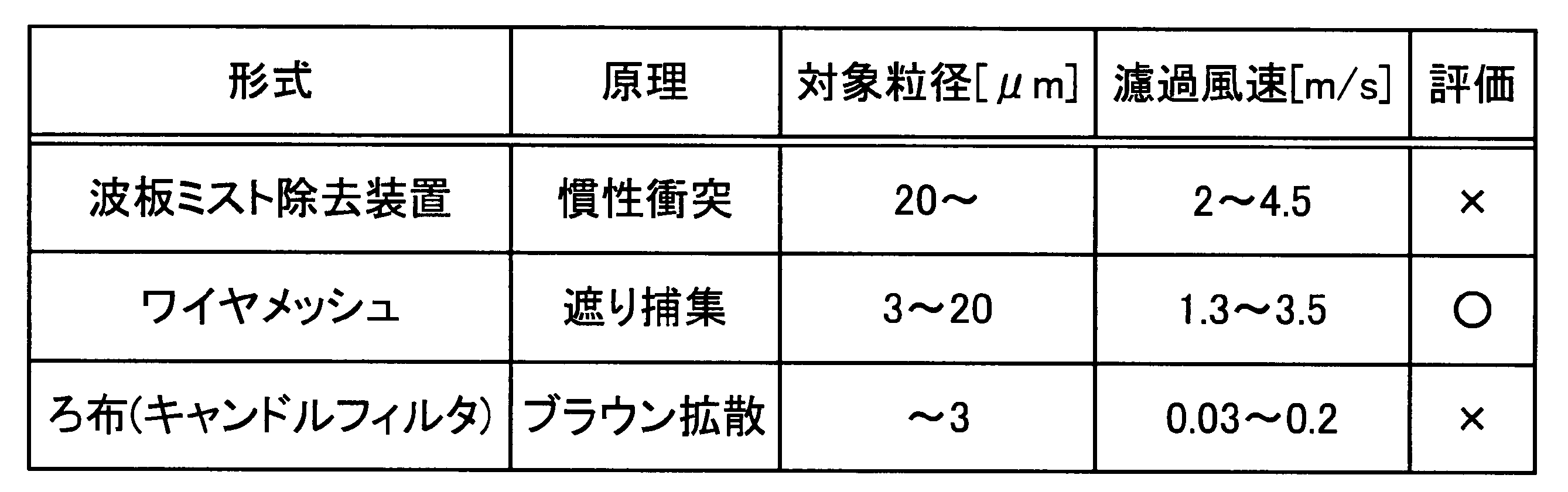
図3は、本発明に係るミスト肥大化の模式図である。なお、図3中、紙面の下側がガス流れ下流側であり紙面の上側がガス流れ上流側である。図3に示すように、ミスト捕集・凝集装置14としてワイヤメッシュ70を用いる場合、ワイヤメッシュ70の表面に付着したSO3ミスト50は、互いに接触して凝集して凝集SO3ミスト51となる。そして、この凝集SO3ミスト51は、ワイヤメッシュ70に沿って流下し、ワイヤメッシュ70の下端部付近からミストドレンとして滴状落下することでミスト捕集・凝集装置14から排出される。
ここで、排ガス12Bの濾過風速を通常のミスト捕集時の限界とされる風速値以上に高くした場合には、凝集SO3ミスト51の流下、落下が一部妨げられ、ワイヤメッシュ70上面側から再飛散するため、ミスト除去効率は低下する。このため、ワイヤメッシュ型のミスト除去装置で限界とされる濾過風速は、例えば2.5~5m/s(ガス中のミスト負荷、ワイヤメッシュ種によって異なる)である。
図4は、濾過風速とミスト除去率との関係の一例を示す図である。図5は、濾過風速と、ミスト付着率及びミスト再飛散率との関係の一例を示す図である。
図4に示す例においては、濾過風速が例えば2.8m/s付近までは、濾過風速の上昇に伴い、ミスト除去率が増加する。しかし濾過風速が2.8m/sを超えると、ワイヤメッシュ70で捕集、凝集したSO3ミストの再飛散が始まる。
図4に示す例においては、濾過風速が例えば2.8m/s付近までは、濾過風速の上昇に伴い、ミスト除去率が増加する。しかし濾過風速が2.8m/sを超えると、ワイヤメッシュ70で捕集、凝集したSO3ミストの再飛散が始まる。
また、図5に示すように、ワイヤメッシュ70に付着したSO3ミストの再飛散率が限界濾過風速(例えば2.8m/s)付近から上昇する。
この限界濾過風速(例えば2.8m/s)を超えた領域では、濾過風速の上昇に伴い、凝集SO3ミスト51の再飛散量が増加するため、図4に示すように、ワイヤメッシュ(ミスト除去装置)70でのミスト除去率は低下する。
しかしながら、ワイヤメッシュ70で付着ミストの凝集が起こっており、再飛散ミストの粒径は流入ミストの粒径よりも大きくなる。よって、この再飛散される凝集SO3ミスト51は、それが核となって、CO2吸収塔16内でさらに肥大化し、CO2吸収塔16の出口に設置するミスト捕集部16Cであるデミスタでのミスト回収率が向上する。この結果、CO2吸収液を同伴するミストの系外飛散量を低減することができる。
以上より、ミスト捕集・凝集装置14での排ガスの濾過風速(V)としては、ミスト捕集の濾過限界風速(例えば2.5m/s)を超える風速(例えばV>2.5m/s)、又は濾過限界風速の1.2~1.5倍の風速とすることが好ましいものとなる。
ここで、ミスト捕集・凝集装置14での濾過風速は、排ガス中のミスト負荷、ワイヤメッシュ種によって異なるので、実機装置において、限界濾過風速が決定した後、その濾過限界風速の1.2~1.5倍の風速とするのが好ましい。
本実施例によれば、ミスト捕集・凝集装置14により、脱硫装置13からの排ガス12Bに含まれるSO3ミスト50同士を結合させて粒径を肥大化させた凝集肥大化ミストである凝集SO3ミスト51とし、この凝集SO3ミスト51を再飛散させて、ガス流れ後流側のCO2吸収液で接触させてCO2を除去するCO2吸収部16A側に導入する。その後、CO2吸収部16Aにおいて、排ガス中に含まれるCO2をCO2吸収液に接触させて除去する際、凝集SO3ミスト51を核としてCO2吸収液が吸収されて肥大化したCO2吸収液肥大化ミスト53とし、該CO2吸収液肥大化ミスト53をミスト捕集部16Cで捕集することができる。これにより、系外にCO2を除去した処理排ガスを排出する際に、CO2吸収液の同伴を大幅に抑制することができる。
実施例2に係る排ガス処理システムについて、以下説明する。本実施例では、実施例1のミスト捕集・凝集装置14を、帯電によりミストを肥大化させるようにしている。図6は、帯電によるミスト肥大化の模式図である。図6に示すように、本実施例では、高圧電源101を備えた放電極102を用いてSO3ミストを帯電させるようにしている。
本実施例では、帯電によるミスト捕集・凝集装置14として、SO3ミスト50を帯電させる放電極102と、低圧損フィルタ120を接地111させている。そして、静電気力を利用して帯電させたSO3ミスト50が、低圧損フィルタ120に付着したミスト同士の静電力による反発を防ぐために、付着SO3ミストを電気的に中性化するようにしている。
本実施例では、静電気力を利用することで、慣性・さえぎり・拡散効果(ブラウン効果)のみを利用する場合に比較して、SO3ミストの捕捉性能が向上する。
また、静電気力を利用することで、慣性・さえぎり・拡散効果(ブラウン効果)のみを利用する場合に比較して、ミスト捕集・凝集装置14を小型化できる。
また、静電気力を利用することで、慣性・さえぎり・拡散効果(ブラウン効果)のみを利用する場合に比較して、ミスト捕集・凝集装置14を小型化できる。
図7は、CO2吸収部16Aの入口排ガス12D中のSO3ミスト濃度と、CO2吸収塔の16ミスト捕集部16Cの出口の放出ガス中アミン濃度との関係図である。
本実施例の場合には、帯電によるミスト捕集・凝集装置14を設けることにより、CO2吸収塔16のミスト捕集部16Cの出口の放出ガス中アミン濃度の低下が、比較例と較べて低下することが確認された。
10 排ガス処理システム
11 ボイラ
12A~12F 排ガス
13 脱硫装置
14 ミスト捕集・凝集装置
15 排ガス冷却塔
16 CO2吸収塔
16A CO2吸収部
16B 水洗部
16C ミスト捕集部
17 吸収液再生塔
18 CO2回収装置
50 SO3ミスト
51 凝集SO3ミスト
53 CO2吸収液肥大化ミスト
11 ボイラ
12A~12F 排ガス
13 脱硫装置
14 ミスト捕集・凝集装置
15 排ガス冷却塔
16 CO2吸収塔
16A CO2吸収部
16B 水洗部
16C ミスト捕集部
17 吸収液再生塔
18 CO2回収装置
50 SO3ミスト
51 凝集SO3ミスト
53 CO2吸収液肥大化ミスト
Claims (7)
- ボイラからの排ガス中の硫黄酸化物を除去する脱硫装置と、
前記脱硫装置の後流側に設けられ、前記排ガスに含まれるミスト同士を結合させて粒径を肥大化させて凝集肥大化ミストとするミスト捕集・凝集装置と、
前記排ガス中に含まれるCO2をCO2吸収液に接触させて除去するCO2吸収部を有するCO2吸収塔と、前記CO2を吸収したCO2吸収液からCO2を放出してCO2を回収すると共に、CO2吸収液を再生する吸収液再生塔とからなるCO2回収装置と、
前記CO2吸収部のガス流れ後流側に設けられ、前記CO2吸収部内で前記凝集肥大化ミストに前記CO2吸収液が吸収されて肥大化したCO2吸収液肥大化ミストを捕集するミスト捕集部とを具備することを特徴とする排ガス処理システム。 - 請求項1において、
前記ミスト捕集・凝集装置での前記排ガスの流速が、ミスト捕集の限界濾過風速を超えることを特徴とする排ガス処理システム。 - 請求項1又は2において、
前記CO2吸収部と前記ミスト捕集部との間に、水洗部を具備することを特徴とする排ガス処理システム。 - 請求項1乃至3のいずれか一つにおいて、
前記ミスト捕集・凝集装置が、ワイヤメッシュによりミストを肥大化させることを特徴とする排ガス処理システム。 - 請求項1乃至3のいずれか一つにおいて、
前記ミスト捕集・凝集装置が、帯電によりミストを肥大化させることを特徴とする排ガス処理システム。 - ボイラからの排ガス中の硫黄酸化物を除去する湿式の脱硫装置からの前記排ガスに含まれるミスト同士を結合させて粒径を肥大化させて凝集肥大化ミストとし、この凝集肥大化ミストを再飛散させて、ガス流れ後流側のCO2吸収液で接触させてCO2を除去するCO2吸収部側に導入し、前記排ガス中に含まれるCO2をCO2吸収液に接触させて除去する際、前記凝集肥大化ミストにCO2吸収液が吸収されて肥大化したCO2吸収液肥大化ミストとし、該CO2吸収液肥大化ミストをミスト捕集部で捕集することを特徴とする排ガス処理方法。
- 請求項6において、
前記凝集肥大化ミストを再飛散する排ガスの流速が、ミスト捕集の限界濾過風速を超えることを特徴とする排ガス処理方法。
Priority Applications (4)
| Application Number | Priority Date | Filing Date | Title |
|---|---|---|---|
| CA2969190A CA2969190C (en) | 2015-01-22 | 2015-09-24 | Flue gas treatment system and method |
| US15/533,460 US10328383B2 (en) | 2015-01-22 | 2015-09-24 | Flue gas treatment system and method |
| EP15878861.2A EP3213809B1 (en) | 2015-01-22 | 2015-09-24 | Exhaust gas treatment system and method |
| US16/403,764 US10610820B2 (en) | 2015-01-22 | 2019-05-06 | Flue gas treatment system and method |
Applications Claiming Priority (2)
| Application Number | Priority Date | Filing Date | Title |
|---|---|---|---|
| JP2015-010715 | 2015-01-22 | ||
| JP2015010715A JP6345127B2 (ja) | 2015-01-22 | 2015-01-22 | 排ガス処理システム及び方法 |
Related Child Applications (2)
| Application Number | Title | Priority Date | Filing Date |
|---|---|---|---|
| US15/533,460 A-371-Of-International US10328383B2 (en) | 2015-01-22 | 2015-09-24 | Flue gas treatment system and method |
| US16/403,764 Division US10610820B2 (en) | 2015-01-22 | 2019-05-06 | Flue gas treatment system and method |
Publications (1)
| Publication Number | Publication Date |
|---|---|
| WO2016117172A1 true WO2016117172A1 (ja) | 2016-07-28 |
Family
ID=56416735
Family Applications (1)
| Application Number | Title | Priority Date | Filing Date |
|---|---|---|---|
| PCT/JP2015/076954 Ceased WO2016117172A1 (ja) | 2015-01-22 | 2015-09-24 | 排ガス処理システム及び方法 |
Country Status (5)
| Country | Link |
|---|---|
| US (2) | US10328383B2 (ja) |
| EP (1) | EP3213809B1 (ja) |
| JP (1) | JP6345127B2 (ja) |
| CA (1) | CA2969190C (ja) |
| WO (1) | WO2016117172A1 (ja) |
Families Citing this family (5)
| Publication number | Priority date | Publication date | Assignee | Title |
|---|---|---|---|---|
| JP6847762B2 (ja) * | 2017-05-15 | 2021-03-24 | 株式会社東芝 | 排ガス成分の除去方法、排ガス成分の除去器および二酸化炭素の分離回収方法ならびに分離回収装置 |
| JP6887099B2 (ja) * | 2017-07-11 | 2021-06-16 | パナソニックIpマネジメント株式会社 | Co2回収装置 |
| CN111450674B (zh) * | 2020-04-23 | 2022-02-08 | 自贡市东方联合机械配套有限公司 | 一种利用去除酸性氧化物排烟管道的尾气再氧化装置 |
| CN112299406B (zh) * | 2020-11-24 | 2021-09-17 | 烟台美尔森石墨有限公司 | 一种负极材料石墨化制备工艺 |
| CN114931849B (zh) * | 2022-06-09 | 2023-06-27 | 浙江菲达环保科技股份有限公司 | 一种分体式硫碳协同湿法脱除装置 |
Citations (9)
| Publication number | Priority date | Publication date | Assignee | Title |
|---|---|---|---|---|
| JPH0893438A (ja) * | 1994-09-20 | 1996-04-09 | Tokai Rubber Ind Ltd | ミスト除去装置 |
| JPH09262432A (ja) * | 1996-03-29 | 1997-10-07 | Kansai Electric Power Co Inc:The | 脱炭酸塔排ガス中の塩基性アミン化合物の回収方法 |
| JP2003053134A (ja) * | 2001-08-21 | 2003-02-25 | Kansai Electric Power Co Inc:The | 脱硫脱炭酸方法 |
| JP2006218415A (ja) * | 2005-02-10 | 2006-08-24 | Kansai Electric Power Co Inc:The | 排気ガスの処理方法及び処理装置 |
| WO2008038348A1 (fr) * | 2006-09-27 | 2008-04-03 | Hitachi Plant Technologies, Ltd. | appareil de traitement des gaz d'échappement contenant un brouillard d'acide sulfurique et son procédé de traitement |
| JP2008238114A (ja) * | 2007-03-28 | 2008-10-09 | Mitsubishi Heavy Ind Ltd | Co2回収装置及びco2吸収液回収方法 |
| JP2009226367A (ja) * | 2008-03-25 | 2009-10-08 | Chiyoda Kako Kensetsu Kk | 脱硫脱炭装置および二酸化炭素除去方法 |
| JP2013006129A (ja) * | 2011-06-22 | 2013-01-10 | Mitsubishi Heavy Ind Ltd | 排ガス処理システム及び排ガス処理方法 |
| JP2014000500A (ja) * | 2012-06-15 | 2014-01-09 | Mitsubishi Heavy Ind Ltd | 排ガス処理システム |
Family Cites Families (17)
| Publication number | Priority date | Publication date | Assignee | Title |
|---|---|---|---|---|
| JPH0779950B2 (ja) | 1989-12-25 | 1995-08-30 | 三菱重工業株式会社 | 燃焼排ガス中のco▲下2▼の除去方法 |
| JPH09187615A (ja) * | 1996-01-12 | 1997-07-22 | Babcock Hitachi Kk | 水蒸気凝集集塵装置及び集塵方法 |
| JP3392646B2 (ja) | 1996-07-26 | 2003-03-31 | 三菱重工業株式会社 | 脱炭酸塔排出ガス中の塩基性アミン化合物の回収方法 |
| JP3856982B2 (ja) * | 1999-05-21 | 2006-12-13 | バブコック日立株式会社 | 脱硫装置出口ガスからの脱塵と水または水蒸気回収方法と装置 |
| JP3969949B2 (ja) | 2000-10-25 | 2007-09-05 | 関西電力株式会社 | アミン回収方法及び装置並びにこれを備えた脱炭酸ガス装置 |
| DE102008011949A1 (de) * | 2008-02-29 | 2010-01-21 | Forschungszentrum Karlsruhe Gmbh | Elektrostatischer Abscheider |
| WO2010125790A1 (ja) * | 2009-04-28 | 2010-11-04 | パナソニック株式会社 | アレー信号処理装置 |
| US20110001126A1 (en) * | 2009-07-02 | 2011-01-06 | Sharp Kabushiki Kaisha | Nitride semiconductor chip, method of fabrication thereof, and semiconductor device |
| NZ591354A (en) | 2010-02-26 | 2012-09-28 | Kraft Foods Global Brands Llc | A low-tack, UV-cured pressure sensitive acrylic ester based adhesive for reclosable packaging |
| CA2800997C (en) | 2010-05-31 | 2015-12-22 | Mitsubishi Heavy Industries, Ltd. | Air pollution control system and method |
| JP2012024718A (ja) * | 2010-07-26 | 2012-02-09 | Babcock Hitachi Kk | Co2除去設備を有する排ガス処理システム |
| JP5636306B2 (ja) * | 2011-02-14 | 2014-12-03 | バブコック日立株式会社 | Co2化学吸収システムの制御方法 |
| JP5725992B2 (ja) * | 2011-06-20 | 2015-05-27 | 三菱日立パワーシステムズ株式会社 | Co2回収設備 |
| JP5959882B2 (ja) * | 2012-03-05 | 2016-08-02 | 三菱日立パワーシステムズ株式会社 | 燃焼排ガス中の二酸化炭素化学吸収システム |
| US8486357B1 (en) | 2012-09-12 | 2013-07-16 | Mitsubishi Heavy Industries, Ltd. | Desulfurization apparatus and method of using condensed water produced therein |
| EP3685907B1 (en) * | 2012-10-11 | 2022-11-30 | Mitsubishi Heavy Industries Engineering, Ltd. | Air pollution control system and air pollution control method |
| US8545782B1 (en) | 2012-10-16 | 2013-10-01 | Mitsubishi Heavy Industries, Ltd. | CO2 recovery apparatus and CO2 recovery method |
-
2015
- 2015-01-22 JP JP2015010715A patent/JP6345127B2/ja active Active
- 2015-09-24 US US15/533,460 patent/US10328383B2/en active Active
- 2015-09-24 CA CA2969190A patent/CA2969190C/en active Active
- 2015-09-24 WO PCT/JP2015/076954 patent/WO2016117172A1/ja not_active Ceased
- 2015-09-24 EP EP15878861.2A patent/EP3213809B1/en active Active
-
2019
- 2019-05-06 US US16/403,764 patent/US10610820B2/en active Active
Patent Citations (9)
| Publication number | Priority date | Publication date | Assignee | Title |
|---|---|---|---|---|
| JPH0893438A (ja) * | 1994-09-20 | 1996-04-09 | Tokai Rubber Ind Ltd | ミスト除去装置 |
| JPH09262432A (ja) * | 1996-03-29 | 1997-10-07 | Kansai Electric Power Co Inc:The | 脱炭酸塔排ガス中の塩基性アミン化合物の回収方法 |
| JP2003053134A (ja) * | 2001-08-21 | 2003-02-25 | Kansai Electric Power Co Inc:The | 脱硫脱炭酸方法 |
| JP2006218415A (ja) * | 2005-02-10 | 2006-08-24 | Kansai Electric Power Co Inc:The | 排気ガスの処理方法及び処理装置 |
| WO2008038348A1 (fr) * | 2006-09-27 | 2008-04-03 | Hitachi Plant Technologies, Ltd. | appareil de traitement des gaz d'échappement contenant un brouillard d'acide sulfurique et son procédé de traitement |
| JP2008238114A (ja) * | 2007-03-28 | 2008-10-09 | Mitsubishi Heavy Ind Ltd | Co2回収装置及びco2吸収液回収方法 |
| JP2009226367A (ja) * | 2008-03-25 | 2009-10-08 | Chiyoda Kako Kensetsu Kk | 脱硫脱炭装置および二酸化炭素除去方法 |
| JP2013006129A (ja) * | 2011-06-22 | 2013-01-10 | Mitsubishi Heavy Ind Ltd | 排ガス処理システム及び排ガス処理方法 |
| JP2014000500A (ja) * | 2012-06-15 | 2014-01-09 | Mitsubishi Heavy Ind Ltd | 排ガス処理システム |
Non-Patent Citations (1)
| Title |
|---|
| See also references of EP3213809A4 * |
Also Published As
| Publication number | Publication date |
|---|---|
| US10610820B2 (en) | 2020-04-07 |
| JP2016131969A (ja) | 2016-07-25 |
| US10328383B2 (en) | 2019-06-25 |
| EP3213809A4 (en) | 2017-11-29 |
| JP6345127B2 (ja) | 2018-06-20 |
| EP3213809A1 (en) | 2017-09-06 |
| CA2969190A1 (en) | 2016-07-28 |
| EP3213809B1 (en) | 2019-08-21 |
| US20170341014A1 (en) | 2017-11-30 |
| US20190255483A1 (en) | 2019-08-22 |
| CA2969190C (en) | 2019-06-04 |
Similar Documents
| Publication | Publication Date | Title |
|---|---|---|
| JP6072055B2 (ja) | 排ガス処理システム及び方法 | |
| JP6125160B2 (ja) | 排ガス処理システム | |
| JP5450540B2 (ja) | Co2回収装置を備えたボイラーの熱回収システム | |
| US10610820B2 (en) | Flue gas treatment system and method | |
| JP5416679B2 (ja) | 排ガス処理方法と装置 | |
| US9216380B1 (en) | Ammonia stripper for a carbon capture system for reduction of energy consumption | |
| JP3856982B2 (ja) | 脱硫装置出口ガスからの脱塵と水または水蒸気回収方法と装置 | |
| JP2015166090A (ja) | 排ガス処理システム及び方法 | |
| JP2015193005A (ja) | 排ガス処理システム及び方法 | |
| CA2796745A1 (en) | Exhaust gas treatment system with carbon dioxide chemical absorption equipment | |
| CN106110853A (zh) | 湿法脱硫装置相变团聚协同脱除细颗粒物的系统及方法 | |
| WO2014024791A1 (ja) | 排ガス処理システム | |
| JP2016131969A5 (ja) | ||
| WO2011152546A1 (ja) | 排ガス処理システム及び方法 | |
| JP2013059727A (ja) | Co2回収装置およびco2回収方法 | |
| JP2018001086A (ja) | 二酸化炭素回収システムおよび排ガス処理方法 | |
| WO2011152547A1 (ja) | 排ガス処理システム及び方法 | |
| JP6173734B2 (ja) | 排ガス処理システム | |
| CN106215674B (zh) | 烟气脱硫装置及方法 |
Legal Events
| Date | Code | Title | Description |
|---|---|---|---|
| 121 | Ep: the epo has been informed by wipo that ep was designated in this application |
Ref document number: 15878861 Country of ref document: EP Kind code of ref document: A1 |
|
| REEP | Request for entry into the european phase |
Ref document number: 2015878861 Country of ref document: EP |
|
| WWE | Wipo information: entry into national phase |
Ref document number: 2969190 Country of ref document: CA |
|
| WWE | Wipo information: entry into national phase |
Ref document number: 15533460 Country of ref document: US |
|
| NENP | Non-entry into the national phase |
Ref country code: DE |