WO2016117285A1 - Élément et générateur électrique - Google Patents
Élément et générateur électrique Download PDFInfo
- Publication number
- WO2016117285A1 WO2016117285A1 PCT/JP2016/000028 JP2016000028W WO2016117285A1 WO 2016117285 A1 WO2016117285 A1 WO 2016117285A1 JP 2016000028 W JP2016000028 W JP 2016000028W WO 2016117285 A1 WO2016117285 A1 WO 2016117285A1
- Authority
- WO
- WIPO (PCT)
- Prior art keywords
- intermediate layer
- silicone rubber
- electric generator
- electrode
- manufactured
- Prior art date
- Legal status (The legal status is an assumption and is not a legal conclusion. Google has not performed a legal analysis and makes no representation as to the accuracy of the status listed.)
- Ceased
Links
Images



Classifications
-
- B—PERFORMING OPERATIONS; TRANSPORTING
- B32—LAYERED PRODUCTS
- B32B—LAYERED PRODUCTS, i.e. PRODUCTS BUILT-UP OF STRATA OF FLAT OR NON-FLAT, e.g. CELLULAR OR HONEYCOMB, FORM
- B32B15/00—Layered products comprising a layer of metal
- B32B15/02—Layer formed of wires, e.g. mesh
-
- B—PERFORMING OPERATIONS; TRANSPORTING
- B32—LAYERED PRODUCTS
- B32B—LAYERED PRODUCTS, i.e. PRODUCTS BUILT-UP OF STRATA OF FLAT OR NON-FLAT, e.g. CELLULAR OR HONEYCOMB, FORM
- B32B15/00—Layered products comprising a layer of metal
- B32B15/04—Layered products comprising a layer of metal comprising metal as the main or only constituent of a layer, which is next to another layer of the same or of a different material
- B32B15/06—Layered products comprising a layer of metal comprising metal as the main or only constituent of a layer, which is next to another layer of the same or of a different material of natural rubber or synthetic rubber
-
- B—PERFORMING OPERATIONS; TRANSPORTING
- B32—LAYERED PRODUCTS
- B32B—LAYERED PRODUCTS, i.e. PRODUCTS BUILT-UP OF STRATA OF FLAT OR NON-FLAT, e.g. CELLULAR OR HONEYCOMB, FORM
- B32B25/00—Layered products comprising a layer of natural or synthetic rubber
- B32B25/02—Layered products comprising a layer of natural or synthetic rubber with fibres or particles being present as additives in the layer
-
- B—PERFORMING OPERATIONS; TRANSPORTING
- B32—LAYERED PRODUCTS
- B32B—LAYERED PRODUCTS, i.e. PRODUCTS BUILT-UP OF STRATA OF FLAT OR NON-FLAT, e.g. CELLULAR OR HONEYCOMB, FORM
- B32B25/00—Layered products comprising a layer of natural or synthetic rubber
- B32B25/10—Layered products comprising a layer of natural or synthetic rubber next to a fibrous or filamentary layer
-
- B—PERFORMING OPERATIONS; TRANSPORTING
- B32—LAYERED PRODUCTS
- B32B—LAYERED PRODUCTS, i.e. PRODUCTS BUILT-UP OF STRATA OF FLAT OR NON-FLAT, e.g. CELLULAR OR HONEYCOMB, FORM
- B32B25/00—Layered products comprising a layer of natural or synthetic rubber
- B32B25/20—Layered products comprising a layer of natural or synthetic rubber comprising silicone rubber
-
- B—PERFORMING OPERATIONS; TRANSPORTING
- B32—LAYERED PRODUCTS
- B32B—LAYERED PRODUCTS, i.e. PRODUCTS BUILT-UP OF STRATA OF FLAT OR NON-FLAT, e.g. CELLULAR OR HONEYCOMB, FORM
- B32B5/00—Layered products characterised by the non- homogeneity or physical structure, i.e. comprising a fibrous, filamentary, particulate or foam layer; Layered products characterised by having a layer differing constitutionally or physically in different parts
- B32B5/02—Layered products characterised by the non- homogeneity or physical structure, i.e. comprising a fibrous, filamentary, particulate or foam layer; Layered products characterised by having a layer differing constitutionally or physically in different parts characterised by structural features of a fibrous or filamentary layer
- B32B5/022—Non-woven fabric
-
- B—PERFORMING OPERATIONS; TRANSPORTING
- B32—LAYERED PRODUCTS
- B32B—LAYERED PRODUCTS, i.e. PRODUCTS BUILT-UP OF STRATA OF FLAT OR NON-FLAT, e.g. CELLULAR OR HONEYCOMB, FORM
- B32B5/00—Layered products characterised by the non- homogeneity or physical structure, i.e. comprising a fibrous, filamentary, particulate or foam layer; Layered products characterised by having a layer differing constitutionally or physically in different parts
- B32B5/02—Layered products characterised by the non- homogeneity or physical structure, i.e. comprising a fibrous, filamentary, particulate or foam layer; Layered products characterised by having a layer differing constitutionally or physically in different parts characterised by structural features of a fibrous or filamentary layer
- B32B5/024—Woven fabric
-
- B—PERFORMING OPERATIONS; TRANSPORTING
- B32—LAYERED PRODUCTS
- B32B—LAYERED PRODUCTS, i.e. PRODUCTS BUILT-UP OF STRATA OF FLAT OR NON-FLAT, e.g. CELLULAR OR HONEYCOMB, FORM
- B32B5/00—Layered products characterised by the non- homogeneity or physical structure, i.e. comprising a fibrous, filamentary, particulate or foam layer; Layered products characterised by having a layer differing constitutionally or physically in different parts
- B32B5/02—Layered products characterised by the non- homogeneity or physical structure, i.e. comprising a fibrous, filamentary, particulate or foam layer; Layered products characterised by having a layer differing constitutionally or physically in different parts characterised by structural features of a fibrous or filamentary layer
- B32B5/028—Net structure, e.g. spaced apart filaments bonded at the crossing points
-
- C—CHEMISTRY; METALLURGY
- C08—ORGANIC MACROMOLECULAR COMPOUNDS; THEIR PREPARATION OR CHEMICAL WORKING-UP; COMPOSITIONS BASED THEREON
- C08G—MACROMOLECULAR COMPOUNDS OBTAINED OTHERWISE THAN BY REACTIONS ONLY INVOLVING UNSATURATED CARBON-TO-CARBON BONDS
- C08G77/00—Macromolecular compounds obtained by reactions forming a linkage containing silicon with or without sulfur, nitrogen, oxygen or carbon in the main chain of the macromolecule
- C08G77/04—Polysiloxanes
- C08G77/14—Polysiloxanes containing silicon bound to oxygen-containing groups
-
- C—CHEMISTRY; METALLURGY
- C08—ORGANIC MACROMOLECULAR COMPOUNDS; THEIR PREPARATION OR CHEMICAL WORKING-UP; COMPOSITIONS BASED THEREON
- C08K—Use of inorganic or non-macromolecular organic substances as compounding ingredients
- C08K3/00—Use of inorganic substances as compounding ingredients
- C08K3/34—Silicon-containing compounds
-
- C—CHEMISTRY; METALLURGY
- C08—ORGANIC MACROMOLECULAR COMPOUNDS; THEIR PREPARATION OR CHEMICAL WORKING-UP; COMPOSITIONS BASED THEREON
- C08K—Use of inorganic or non-macromolecular organic substances as compounding ingredients
- C08K3/00—Use of inorganic substances as compounding ingredients
- C08K3/34—Silicon-containing compounds
- C08K3/36—Silica
-
- C—CHEMISTRY; METALLURGY
- C08—ORGANIC MACROMOLECULAR COMPOUNDS; THEIR PREPARATION OR CHEMICAL WORKING-UP; COMPOSITIONS BASED THEREON
- C08K—Use of inorganic or non-macromolecular organic substances as compounding ingredients
- C08K5/00—Use of organic ingredients
- C08K5/54—Silicon-containing compounds
- C08K5/549—Silicon-containing compounds containing silicon in a ring
-
- C—CHEMISTRY; METALLURGY
- C08—ORGANIC MACROMOLECULAR COMPOUNDS; THEIR PREPARATION OR CHEMICAL WORKING-UP; COMPOSITIONS BASED THEREON
- C08L—COMPOSITIONS OF MACROMOLECULAR COMPOUNDS
- C08L83/00—Compositions of macromolecular compounds obtained by reactions forming in the main chain of the macromolecule a linkage containing silicon with or without sulfur, nitrogen, oxygen or carbon only; Compositions of derivatives of such polymers
- C08L83/04—Polysiloxanes
-
- H—ELECTRICITY
- H01—ELECTRIC ELEMENTS
- H01G—CAPACITORS; CAPACITORS, RECTIFIERS, DETECTORS, SWITCHING DEVICES, LIGHT-SENSITIVE OR TEMPERATURE-SENSITIVE DEVICES OF THE ELECTROLYTIC TYPE
- H01G7/00—Capacitors in which the capacitance is varied by non-mechanical means; Processes of their manufacture
- H01G7/02—Electrets, i.e. having a permanently-polarised dielectric
-
- H—ELECTRICITY
- H10—SEMICONDUCTOR DEVICES; ELECTRIC SOLID-STATE DEVICES NOT OTHERWISE PROVIDED FOR
- H10N—ELECTRIC SOLID-STATE DEVICES NOT OTHERWISE PROVIDED FOR
- H10N30/00—Piezoelectric or electrostrictive devices
- H10N30/01—Manufacture or treatment
- H10N30/04—Treatments to modify a piezoelectric or electrostrictive property, e.g. polarisation characteristics, vibration characteristics or mode tuning
-
- H—ELECTRICITY
- H10—SEMICONDUCTOR DEVICES; ELECTRIC SOLID-STATE DEVICES NOT OTHERWISE PROVIDED FOR
- H10N—ELECTRIC SOLID-STATE DEVICES NOT OTHERWISE PROVIDED FOR
- H10N30/00—Piezoelectric or electrostrictive devices
- H10N30/30—Piezoelectric or electrostrictive devices with mechanical input and electrical output, e.g. functioning as generators or sensors
-
- H—ELECTRICITY
- H10—SEMICONDUCTOR DEVICES; ELECTRIC SOLID-STATE DEVICES NOT OTHERWISE PROVIDED FOR
- H10N—ELECTRIC SOLID-STATE DEVICES NOT OTHERWISE PROVIDED FOR
- H10N30/00—Piezoelectric or electrostrictive devices
- H10N30/80—Constructional details
- H10N30/85—Piezoelectric or electrostrictive active materials
- H10N30/857—Macromolecular compositions
-
- B—PERFORMING OPERATIONS; TRANSPORTING
- B32—LAYERED PRODUCTS
- B32B—LAYERED PRODUCTS, i.e. PRODUCTS BUILT-UP OF STRATA OF FLAT OR NON-FLAT, e.g. CELLULAR OR HONEYCOMB, FORM
- B32B2262/00—Composition or structural features of fibres which form a fibrous or filamentary layer or are present as additives
- B32B2262/10—Inorganic fibres
- B32B2262/106—Carbon fibres, e.g. graphite fibres
-
- B—PERFORMING OPERATIONS; TRANSPORTING
- B32—LAYERED PRODUCTS
- B32B—LAYERED PRODUCTS, i.e. PRODUCTS BUILT-UP OF STRATA OF FLAT OR NON-FLAT, e.g. CELLULAR OR HONEYCOMB, FORM
- B32B2307/00—Properties of the layers or laminate
- B32B2307/20—Properties of the layers or laminate having particular electrical or magnetic properties, e.g. piezoelectric
-
- B—PERFORMING OPERATIONS; TRANSPORTING
- B32—LAYERED PRODUCTS
- B32B—LAYERED PRODUCTS, i.e. PRODUCTS BUILT-UP OF STRATA OF FLAT OR NON-FLAT, e.g. CELLULAR OR HONEYCOMB, FORM
- B32B2307/00—Properties of the layers or laminate
- B32B2307/20—Properties of the layers or laminate having particular electrical or magnetic properties, e.g. piezoelectric
- B32B2307/202—Conductive
-
- B—PERFORMING OPERATIONS; TRANSPORTING
- B32—LAYERED PRODUCTS
- B32B—LAYERED PRODUCTS, i.e. PRODUCTS BUILT-UP OF STRATA OF FLAT OR NON-FLAT, e.g. CELLULAR OR HONEYCOMB, FORM
- B32B2457/00—Electrical equipment
-
- B—PERFORMING OPERATIONS; TRANSPORTING
- B32—LAYERED PRODUCTS
- B32B—LAYERED PRODUCTS, i.e. PRODUCTS BUILT-UP OF STRATA OF FLAT OR NON-FLAT, e.g. CELLULAR OR HONEYCOMB, FORM
- B32B2457/00—Electrical equipment
- B32B2457/16—Capacitors
-
- H—ELECTRICITY
- H01—ELECTRIC ELEMENTS
- H01G—CAPACITORS; CAPACITORS, RECTIFIERS, DETECTORS, SWITCHING DEVICES, LIGHT-SENSITIVE OR TEMPERATURE-SENSITIVE DEVICES OF THE ELECTROLYTIC TYPE
- H01G7/00—Capacitors in which the capacitance is varied by non-mechanical means; Processes of their manufacture
- H01G7/02—Electrets, i.e. having a permanently-polarised dielectric
- H01G7/028—Electrets, i.e. having a permanently-polarised dielectric having a heterogeneous dielectric
-
- H—ELECTRICITY
- H02—GENERATION; CONVERSION OR DISTRIBUTION OF ELECTRIC POWER
- H02N—ELECTRIC MACHINES NOT OTHERWISE PROVIDED FOR
- H02N1/00—Electrostatic generators or motors using a solid moving electrostatic charge carrier
- H02N1/06—Influence generators
- H02N1/08—Influence generators with conductive charge carrier, i.e. capacitor machines
Definitions
- the present invention relates to an element and an electric generator.
- the system utilizing the piezoelectric element uses mainly a ceramic-based piezoelectric element, and utilizes a phenomenon that electric charge is induced at a surface of the piezoelectric element when distortion is applied to the piezoelectric element due to vibrations.
- the system utilizing the electrostatic induction typically uses an electret dielectric retaining electric charge semipermanently (for example, see PTL 1 to PTL 5).
- the electret dielectric used in the aforementioned literatures is a material capable of charging the dielectric to generate an electrostatic field semipermanently. Electric charge is induced to an electrode through electrostatic induction by changing a relative position between the electret dielectric and the electrode disposed being distant from the electret dielectric due to vibrations. As a result, electricity is generated.
- the system utilizing the piezoelectric element uses mainly a ceramic-based piezoelectric element, there are problems that the element does not have flexibility and the element is easily broken.
- a charging treatment needs to be performed on a dielectrics, when an electret derivative for use is produced.
- Examples of the charging treatment include corona discharge, and a plasma treatment.
- these treatments have a problem that a large quantity of electricity is required.
- a flexibility of an element is not sufficient.
- a mechanical capacity varying system is typically disposed, it is difficult to realize a flexible element.
- JP-A Japanese Patent Application Laid-Open
- JP-B Japanese Patent (JP-B) No. 5563746 JP-A No. 2012-164727 JP-A No. 2012-164917 JP-A No. 2014-027756
- the present invention aims to provide element having excellent flexibility, and a high electricity generation performance.
- the element of the present invention includes a first electrode, an intermediate layer made of a silicone rubber composition containing a silicone rubber, and a second electrode, where the first electrode, the intermediate layer, and the second electrode are disposed in this order.
- a peak intensity ratio (1095 ⁇ 5 cm -1 /1025 ⁇ 5 cm -1 ) of an infrared absorption spectrum of the intermediate layer varies along a vertical direction relative to a surface of the first electrode, and to a surface of the second electrode.
- the present invention can provide an element having excellent flexibility and a high electricity generation performance.
- FIG. 1 is a schematic cross-sectional view illustrating one example of the element of the present invention.
- FIG. 2 is a schematic cross-sectional view illustrating another example of the element of the present invention.
- FIG. 3 is an enlarged view illustrating one example of a cross-section of an intermediate layer in the element of the present invention.
- FIG. 4 is an enlarged view illustrating one example of a cross-section of another intermediate layer in the element of the present invention.
- FIG. 5 is an enlarged view illustrating one example of a cross-section of another intermediate layer in the element of the present invention.
- FIG. 6 is an enlarged view illustrating one example of a cross-section of another intermediate layer in the element of the present invention.
- FIG. 1 is a schematic cross-sectional view illustrating one example of the element of the present invention.
- FIG. 2 is a schematic cross-sectional view illustrating another example of the element of the present invention.
- FIG. 3 is an enlarged view illustrating one example of a cross-section of an intermediate layer
- FIG. 7 is a schematic cross-sectional view illustrating one example of the electric generator of the present invention.
- FIG. 8 is a schematic cross-sectional view illustrating another example of the electric generator of the present invention.
- FIG. 9 depicts infrared absorption spectrums obtained by measuring the intermediate layer produced in Example 1 at positions with different depths of the intermediate layer.
- the element of the present invention includes a first electrode, an intermediate layer, and a second electrode, disposed in this order.
- the element of the present invention may further include other members, if necessary.
- a material, shape, size, and structure of each of the first electrode and the second electrode are appropriately selected depending on the intended purpose without any limitation.
- the material, shape, size, and structure of the first electrode may be the same or different from the material, shape, size, and structure of the second electrode, but the material, shape, size, and structure of the first electrode are preferably the same as the material, shape, size, and structure of the second electrode.
- Examples of the material of the first electrode and the second electrode include metal, a carbon-based conductive material, and a conductive rubber composition.
- metal examples include gold, silver, copper, iron, aluminium, stainless steel, tantalum, nickel, and phosphor bronze.
- Examples of the carbon-based conductive material include graphite, carbon fiber, and carbon nanotubes.
- Examples of the conductive rubber composition include a composition containing conductive filler and rubber.
- Examples of the conductive filler include a carbon material (e.g., Ketjenblack, acetylene black, graphite, carbon fiber, carbon fiber (CF), carbon nanofiber (CNF), and carbon nanotube (CNTs)), metal filler (e.g., gold, silver, platinum, copper, iron, aluminium, and nickel), a conductive polymer material (e.g., a derivative of any of polythiophene, polyacetylene, polyaniline, polypyrrole, poly(p-phenylene), and poly(p-phenylene)vinylene derivative, or the derivatives doped with a dopant, such as anions, and cations), and an ionic liquid.
- a carbon material e.g., Ketjenblack, acetylene black, graphite, carbon fiber, carbon fiber (CF), carbon nanofiber (CNF), and carbon nanotube (CNTs)
- Examples of the rubber include silicone rubber, modified silicone rubber, acrylic rubber, chloroprene rubber, polysulfide rubber, urethane rubber, isobutyl rubber, fluorosilicone rubber, ethylene rubber, and natural rubber (latex). These may be used alone, or in combination.
- Examples of the form of the first electrode and the form of the second electrode include a sheet, a film, a thin film, a woven fabric, a non-woven fabric, a mesh, and a sponge.
- the form of the first electrode and the form of the second electrode may be each a non-woven fabric formed by overlapping the carbon material in the form of fibers.
- the shape of the first electrode and the shape of the second electrode are not particularly limited, and are appropriately selected depending on a shape of an element.
- the size of the first electrode and the size of the second electrode are not particularly limited, and are appropriately selected depending on a shape of an element.
- the average thickness of the first electrode and the average thickness of the second electrode can be appropriately selected depending on a structure of an element.
- the average thickness of the first electrode and the average thickness of the second electrode are preferably 0.01 ⁇ m to 1 mm, more preferably 0.1 ⁇ m to 500 ⁇ m.
- the average thickness of the first electrode and the average thickness of the second electrode are 0.01 ⁇ m or greater, an appropriate mechanical strength can be attained, and thus conductivity of a resulting element improves.
- the average thickness of the first electrode and the average thickness of the second electrode are 1 mm or less, a resulting element is deformable, and thus excellent electricity generation performance can be attained.
- the intermediate layer is made of a silicone rubber composition containing silicone rubber.
- a peak intensity ratio (1095 ⁇ 5 cm -1 /1025 ⁇ 5 cm -1 ) of an infrared absorption spectrum of the intermediate layer varies along a vertical direction (the depth direction of the intermediate layer) relative to a surface of the first electrode, and to a surface of the second electrode. It is assumed that a potential difference is caused at both ends of the intermediate layer upon application of a distortion to generate electricity, as the peak intensity ratio of the intermediate layer composed of the silicone rubber composition varies along the depth direction of the intermediate layer.
- peak intensity ratio (1095 ⁇ 5 cm -1 /1025 ⁇ 5 cm -1 ) of an infrared absorption spectrum of the intermediate layer varies is not particularly limited, as long as the peak intensity ratio varies along the depth direction of the intermediate layer, preferably that the intermediate layer has a region the peak intensity ratio of which is different.
- the peak intensity ratio may change continuously, or discontinuously. Either of the peak intensity ratio of the intermediate layer at the first electrode side, or the peak intensity ratio of the intermediate layer at the second electrode side may be higher than the other.
- the infrared absorption spectrum of the intermediate layer can be measured by cutting out a sample piece from the intermediate layer, and analyzing the depth direction (cross-section) of the sample by means of an infrared microspectrometric device.
- the silicone rubber is known to have two absorption peaks attributed to Si-O-Si stretching vibrations in the region of 1150 cm -1 to 1000 cm -1 . The peak at the higher wavelength side is attributed to symmetric stretching vibrations, and the peak at the lower wavelength side is attributed to asymmetric stretching vibrations (see I. Soga, S. Granick, Macromolecules, 1998, 31, 5450).
- absorption peaks of the silicone rubber of the intermediate layer which are attributed to Si-O-Si stretching vibrations, are observed at around 1095 cm -1 , and around 1025 cm -1 .
- the peak intensity ratio (1095 ⁇ 5 cm -1 /1025 ⁇ 5 cm -1 ) of the infrared absorption spectrum varies along the depth direction of the intermediate layer. Specifically, there is a region where a state of the Si-O-Si bond of the silicone rubber is different within the intermediate layer. It is assumed that a potential difference is caused at both ends of the intermediate layer upon application of distortion because of the aforementioned region, to thereby generate electricity.
- the variation rate of the peak intensity ratio is preferably 0.95 or less.
- the variation rate is a value obtained from: a peak intensity ratio (1095 ⁇ 5 cm -1 /1025 ⁇ 5 cm -1 ) of an infrared absorption spectrum of the intermediate layer measured at a position that is 1 ⁇ m in depth from a surface of the intermediate layer at a side of the first electrode; and a peak intensity ratio (1095 ⁇ 5 cm -1 /1025 ⁇ 5 cm -1 ) of an infrared absorption spectrum of the intermediate layer measured at a position that is 1 ⁇ m in depth from a surface of the intermediate layer at a side of the second electrode, by dividing the peak intensity ratio that is smaller by the peak intensity ratio that is larger.
- the variation rate of the peak intensity ratio is 0.95 or less, the peak intensity ratio is different along the depth direction of the intermediate layer, which means there is a region where a state of the Si-O-Si bond of the silicone rubber is different within the intermediate layer.
- Examples of a method for varying the peak intensity ratio (1095 ⁇ 5 cm -1 /1025 ⁇ 5 cm -1 ) of the infrared absorption spectrum along the depth direction of the intermediate layer include: a method containing performing a surface modification treatment on the intermediate layer; and a method containing adding a silicon atom-containing compound into the intermediate layer.
- the intermediate layer is made of a silicone rubber composition.
- the silicone rubber composition includes silicone rubber, preferably further includes filler, and may further contain other ingredients, if necessary.
- the silicone rubber is appropriately selected depending on the intended purpose without any limitation, provided that the silicone rubber is rubber containing organopolysiloxane bonds.
- the silicone rubber include dimethyl silicone rubber, methyl phenyl silicone rubber, and modified silicone rubber (e.g., acryl-modified silicone rubber, alkyd-modified silicone rubber, ester-modified silicone rubber, and epoxy-modified silicone rubber). These may be used alone, or in combination.
- the silicone rubber may be appropriately synthesized for use, or selected from commercial products.
- Examples of the commercial product of the silicone rubber include: IVS4312, TSE3033, and XE14-C2042 (manufactured by Momentive Performance Materials Inc.); KE-1935 (manufactured by Shin-Etsu Chemical Co., Ltd.); and DY35-2083 (manufactured by Dow Corning Toray Co., Ltd.). These may be used alone, or in combination.
- the filler is appropriately selected depending on the intended purpose without any limitation.
- examples of the filler include organic filler, inorganic filler, and organic-inorganic composite filler. It is assumed that a capacitance of the intermediate layer changes even with a small distortion, as the filler is included in the intermediate, hence increasing a quantity of electricity generating.
- the organic filler is not particularly limited, as long as the organic filler is an organic compound.
- the organic filler include acryl particles, polystyrene particles, melamine particles, fluororesin particles (e.g., polytetrafluoroethylene), silicone powder (e.g., silicone resin powder, silicone rubber powder, and silicone complex powder), rubber powder, wood flour, pulps, and starch.
- the inorganic filler is not particularly limited, as long as the inorganic filler is an inorganic compound.
- the inorganic filler include oxide, hydroxide, carbonate, sulfate, silicate, nitride, carbon, metal, and other compounds.
- the oxide include silica, diatomaceous earth, alumina, zinc oxide, titanium oxide, iron oxide, and magnesium oxide.
- the hydroxide include aluminium hydroxide, calcium hydroxide, and magnesium hydroxide.
- the carbonate include calcium carbonate, magnesium carbonate, barium carbonate, and hydrotalcite.
- the sulfate include aluminium sulfate, calcium sulfate, and barium sulfate.
- silicate examples include calcium silicate (e.g., wollastonite, and xonotlite), zirconium silicate, kaolin, talc, mica, zeolite, pearlite, bentonite, montmorillonite, sericite, activated clay, glass, and hollow glass beads.
- nitride examples include aluminium nitride, silicon nitride, and boron nitride.
- carbon include Ketjenblack, acetylene black, graphite, carbon fiber, carbon fiber , carbon nanofiber, carbon nanotubes, fullerene (including derivatives), and graphene.
- metal examples include gold, silver, platinum, copper, iron, aluminium, and nickel.
- the inorganic filler may be processed with a surface treatment.
- the organic-inorganic composite filler is not particularly limited, as long as the organic-inorganic composite filler is a compound, in which an organic compound and an inorganic compound are combined at molecular level.
- Examples of the organic-inorganic composite filler include silica-acryl composite particles, and silsesquioxane.
- a silicon atom-containing compound is preferable, because addition of the silicon atom-containing compound can increase a quantity of electricity generating.
- the silicon atom-containing compound include silica, diatomaceous earth, silicate (e.g., calcium silicate (such as wollastonite, and xonotlite), zirconium silicate, kaolin, talc, mica, zeolite, pearlite, bentonite, montmorillonite, sericite, activated clay, glass, and hollow glass beads), silicone powder (e.g., silicone resin powder, silicone rubber powder, and silicone composite powder), silica-acryl composite particles, and silsesquioxane.
- silicate e.g., calcium silicate (such as wollastonite, and xonotlite), zirconium silicate, kaolin, talc, mica, zeolite, pearlite, bentonite, montmorillonite, sericite, activated clay, glass, and hollow glass beads
- silicone powder
- silica examples include Sylysia 430 (manufactured by Fuji Silysia Chemical Ltd.), and HS-207 (manufactured by NIPPON STEEL & SUMIKIN MATERIALS Co., Ltd.).
- examples of the kaolin include: ST-100, ST-KE, and ST-CROWN (manufactured by SHIRAISHI CALCIUM KAISHA, LTD.); and RC-1, Glomax LL, and Satintone No. 5 (manufactured by TAKEHARA KAGAKU KOGYO CO., LTD.).
- Examples of the talc include: JM-209, and JM-309 (manufactured by Asada Milling Co., Ltd.); Ptalc, PHtalc, Microlight, and High micron HE5 (manufactured by TAKEHARA KAGAKU KOGYO CO., LTD.); and D-1000, D-800, SG-95, and P-3 (manufactured by NIPPON TALC Co., Ltd.).
- Examples of the mica include A-11 (manufactured by YAMAGUCHI MICA CO., LTD.), and PDM-5B (manufactured by TOPY INDUSTRIES LIMITED).
- Examples of the wollastonite include: Wollasto JET30w, and Wollasto 325 (manufactured by Asada Milling Co., Ltd.); and ST-40F (manufactured by SHIRAISHI CALCIUM KAISHA, LTD.).
- Examples of the zeolite include SP#2300 and SP#600 (manufactured by NITTO FUNKA KOGYO K.K.).
- Examples of the barium titanate include 208108 (manufactured by Sigma-Aldrich Co., LLC.).
- Examples of the strontium titanate include 396141 (manufactured by Sigma-Aldrich Co., LLC.).
- Examples of the sericite include ST-501 (manufactured by SHIRAISHI CALCIUM KAISHA, LTD.).
- Examples of the diatomaceous earth include CT-C499 (manufactured by SHIRAISHI CALCIUM KAISHA, LTD.)
- Examples of the hollow glass beads include Sphericel 110P8 (manufactured by Potters-Ballotini Co., Ltd.).
- Examples of the acryl particles include FH-S005 (manufactured by TOYOBO CO., LTD.).
- Examples of the polystyrene particles include 19520-500 (manufactured by Techno Chemical Corporation).
- silicone resin powder examples include Tospearl 120 (manufactured by Momentive Performance Materials Inc.), and KMP-590 (manufactured by Shin-Etsu Chemical Co., Ltd.)
- silicone rubber powder examples include EP-2600 (manufactured by Dow Corning Toray Co., Ltd.), and KMP-597 (manufactured by Shin-Etsu Chemical Co., Ltd.).
- silicone composite powder examples include KMP-605, and X-52-7030 (manufactured by Shin-Etsu Chemical Co., Ltd.).
- silica-acryl composite particles examples include Soliostar RA (manufactured by NIPPON SHOKUBAI CO., LTD.).
- Examples of the silsesquioxane include PPS-octamethyl substitute 526835, PPS-octaphenyl substitute 526851, and PPS-octavinyl substitute 475424 (manufactured by Sigma-Aldrich Co., LLC.).
- Examples of the titanium oxide include CR-90 (manufactured by ISHIHARA SANGYO KAISHA, LTD.).
- Examples of the iron oxide include Toda Color 100ED (manufactured by TODA KOGYO CORP.).
- Examples of the carbon nanofiber include VGCF-H (manufactured by SHOWA DENKO K.K.).
- Examples of the fullerene include nanom purple ST (manufactured by Frontier Carbon Corporation).
- the average particle diameter of the filler is appropriately selected depending on the intended purpose without any limitation.
- the average particle diameter of the filler is preferably 0.01 ⁇ m to 30 ⁇ m, more preferably 0.1 ⁇ m to 10 ⁇ m.
- an electricity generation performance of a resulting element may improve.
- the average particle diameter of the filler is 30 ⁇ m or less, the intermediate layer has excellent flexibility, and thus an electricity generation performance of a resulting element may be enhanced.
- the average particle diameter can be measured in accordance with a conventional method, for example, by means of Microtrac HRA (manufactured by NIKKISO CO., LTD.).
- the amount of the filler relative to 100 parts by mass of the silicone rubber is preferably 0.1 parts by mass to 100 parts by mass, more preferably 1 part by mass to 50 parts by mass.
- the amount of the filler is 0.1 parts by mass or greater, an electricity generation performance of a resulting element may be improved.
- the amount of the filler is 100 parts by mass or less, moreover, the intermediate layer has excellent flexibility, and the electricity generation performance can be enhanced.
- ingredients are appropriately selected depending on the intended purpose without any limitation.
- examples of the ingredients include rubber, and additives.
- the amount of the ingredients can be appropriately selected, provided that the ingredients of such amount does not impart an obtainable effect of the present invention.
- Examples of the rubber include fluorosilicone rubber, acrylic rubber, chloroprene rubber, natural rubber (latex), urethane rubber, fluororubber, and ethylene propylene rubber.
- Examples of the additives include a crosslinking agent, an antidegradant, a heat-proof agent, and a colorant.
- the silicone rubber composition can be prepared by mixing the silicone rubber, the filler, and optional other ingredients, and kneading and dispersing the mixture.
- the formation method of the intermediate layer is appropriately selected depending on the intended purpose without any limitation.
- Examples of the formation method include a method including applying the silicone rubber composition onto a base material by blade coating, die coating, or dip coating, followed by curing the silicone rubber composition with heat or electron beams.
- the intermediate layer may be a single layer, or multiple layers.
- the average thickness of the intermediate layer is appropriately selected depending on the intended purpose without any limitation.
- the average thickness of the intermediate layer is preferably 1 ⁇ m to 10 mm, more preferably 20 ⁇ m to 200 ⁇ m. When the average thickness is 1 ⁇ m or greater, an appropriate mechanical strength can be attained, and thus an electricity generation performance of a resulting element improves. When the average thickness is 10 mm or less, the intermediate layer has excellent flexibility, and thus an electricity generation performance of a resulting element improves.
- the intermediate layer is preferably insulation.
- the intermediate layer preferably has volume resistivity of 10 8 ⁇ cm or greater, more preferably 10 10 ⁇ cm or greater. By adjusting the volume resistivity of the intermediate layer to the aforementioned preferred numerical range, an excellent electricity generation performance can be achieved.
- the intermediate layer is preferably subjected to a surface modification treatment.
- the surface modification treatment is appropriately selected depending on the intended purpose without any limitation, provided that the surface modification treatment is a treatment where a certain degree of radiation energy is applied to a material to modify the material.
- Examples of the surface modification treatment include a plasma treatment, a corona discharge treatment, an electron-beam irradiation treatment, a UV-ray irradiation treatment, an ozone treatment, and a radial-ray (X-ray, ⁇ -ray, ⁇ -ray, ⁇ -ray, or neutron) irradiation treatment.
- preferred in view of a processing speed are a plasma treatment, a corona discharge treatment, and an electron-beam irradiation treatment.
- a plasma generating device is, for example, an atmospheric pressure plasma device, as well as a parallel-plate plasma device, a capacity-coupled plasma device, or an inductively-coupled plasma device.
- the plasma treatment is preferably a low-pressure plasma treatment.
- the reaction pressure of the plasma treatment is appropriately selected depending on the intended purpose without any limitation.
- the reaction pressure is preferably 0.05 Pa to 100 Pa, more preferably 1 Pa to 20 Pa.
- the reaction atmosphere of the plasma treatment is appropriately selected depending on the intended purpose without any limitation.
- gas such as inert gas, noble gas, and oxygen, is effective as the reaction atmosphere.
- the reaction atmosphere is preferably argon in view of continuity of an effect.
- the oxygen partial pressure of the reaction atmosphere be adjusted to 5,000 ppm or less.
- generation of ozone can be suppressed, and use of an ozone processing device can be avoided.
- the electricity radiation does in the plasma treatment is defined by (output ⁇ irradiation duration).
- the electricity radiation does is preferably 5 Wh to 200 Wh, more preferably 10 Wh to 50 Wh.
- an electricity generating function can be imparted to the intermediate layer, and durability can be maintained, as an excessive amount of the energy is not applied.
- the applied energy (cumulative energy) in the corona discharge treatment is preferably 6 J/cm 2 to 300 J/cm 2 , more preferably 12 J/cm 2 to 60 J/cm 2 . When the applied energy is within the aforementioned preferred range, excellent electricity generation performance and durability can be achieved.
- the applied voltage in the corona discharge treatment is preferably 50 V to 150 V, more preferably 100 V.
- the reaction atmosphere of the corona discharge treatment is preferably air.
- the radiation dose of the electron-beam irradiation treatment is preferably 1 kGy or greater, more preferably 300 kGy to 10 MGy. When the radiation dose is within the aforementioned preferred range, an electricity generating function can be imparted to the intermediate layer, and durability can be maintained, as an excessive amount of the energy is not applied.
- the reaction atmosphere of the electron-beam irradiation treatment is appropriately selected depending on the intended purpose without any limitation.
- the reaction atmosphere is preferably an atmosphere the oxygen partial pressure of which is adjusted to 5,000 ppm or less by filling with inert gas, such as argon, neon, helium, and nitrogen. When the oxygen partial pressure of the reaction atmosphere is 5,000 ppm or less, generation of ozone can be suppressed, and use of an ozone processing device can be avoided.
- UV rays used in the UV-ray irradiation treatment preferably have wavelengths of 200 nm to 365 nm, more preferably 240 nm to 320 nm.
- the cumulative radiation of the UV-ray irradiation treatment is preferably 5 J/cm 2 to 500 J/cm 2 , more preferably 50 J/cm 2 to 400 J/cm 2 .
- an electricity generating function can be imparted to the intermediate layer, and durability can be maintained, as an excessive amount of the energy is not applied.
- the reaction atmosphere of the UV-ray irradiation treatment is appropriately selected depending on the intended purpose without any limitation.
- the reaction atmosphere is preferably an atmosphere the oxygen partial pressure of which is adjusted to 5,000 ppm or less by filling with inert gas, such as argon, neon, helium, and nitrogen.
- inert gas such as argon, neon, helium, and nitrogen.
- an interlayer adhesion is enhanced by exciting or oxidizing a material through a plasma treatment, a corona discharge treatment, a UV-ray irradiation treatment, or an electron-beam irradiation treatment, to thereby form active groups.
- these techniques are only limited to the application between layers, and are not suitable for an outermost surface, as lubricity are lowered.
- a reaction of any of the aforementioned treatments is performed in an oxygen-rich state, to effectively introduce reaction active groups (hydroxyl groups). Accordingly, the aforementioned related art is fundamentally different from the surface modification treatment performed in the present invention.
- the surface modification treatment is a treatment (e.g., a plasma treatment) that is performed in a reaction environment of a low oxygen content with reduced pressure. Therefore, the surface modification treatment accelerates re-crosslinking and bonding of the surface to improve durability, for example, owing to “an increase of Si-O bonds having high bonding energy,” as well as improving lubricity owing to “high density because of an improved crosslinking density.”
- FIG. 3 is a schematic cross-sectional view illustrating an enlarged example of a microstructure of the intermediate layer 4 constituting the element of the present invention.
- the intermediate layer 4 is made of a silicone rubber composition containing silicone rubber 7.
- a peak intensity ratio (1095 ⁇ 5 cm -1 /1025 ⁇ 5 cm -1 ) of the infrared absorption spectrum of the intermediate layer 4 varies along a vertical direction (depth direction of the intermediate layer) relative to the surface of the first electrode and the surface of the second electrode.
- the region 9 where the peak intensity ratio of the intermediate layer is small is continuously changed to the region 10 where the peak intensity ratio of the intermediate layer is large.
- FIG. 4 is a schematic cross-sectional view illustrating enlarged another example of a microstructure of the intermediate layer 4 constituting the element of the present invention.
- the intermediate layer 4 is made of a silicone rubber composition containing silicone rubber 7.
- a peak intensity ratio (1095 ⁇ 5 cm -1 /1025 ⁇ 5 cm -1 ) of the infrared absorption spectrum of the intermediate layer 4 varies along a vertical direction (depth direction of the intermediate layer) relative to the surface of the first electrode and the surface of the second electrode.
- the region 9 where the peak intensity ratio of the intermediate layer is small and the region 10 where the peak intensity ratio of the intermediate layer is large is separated at an interface, and the peak intensity ratio is discontinuously changed
- FIG. 5 is a cross-sectional view illustrating enlarged another example of a microstructure of the intermediate layer 4 constituting the element of the present invention.
- the intermediate layer 4 is made of a silicone rubber composition containing silicone rubber 7 and filler 8.
- a peak intensity ratio (1095 ⁇ 5 cm -1 /1025 ⁇ 5 cm -1 ) of the infrared absorption spectrum of the intermediate layer 4 varies along a vertical direction (depth direction of the intermediate layer) relative to the surface of the first electrode and the surface of the second electrode.
- the region 9 where the peak intensity ratio of the intermediate layer is small and the region 10 where the peak intensity ratio of the intermediate layer is large is separated at an interface, and the peak intensity ratio is discontinuously changed
- the filler 8 may be homogeneously dispersed in the intermediate layer 4, or locally disposed in the region 9 where the peak intensity of the intermediate layer is small, or the region 10 where the peak intensity of the intermediate layer is large.
- FIG. 6 is a cross-sectional view illustrating enlarged another example of a microstructure of the intermediate layer 4 constituting the element of the present invention.
- the intermediate layer 4 is made of a silicone rubber composition containing silicone rubber 7 and filler 8.
- a peak intensity ratio (1095 ⁇ 5 cm -1 /1025 ⁇ 5 cm -1 ) of the infrared absorption spectrum of the intermediate layer 4 varies along a vertical direction (depth direction of the intermediate layer) relative to the surface of the first electrode and the surface of the second electrode.
- the region 9 where the peak intensity ratio of the intermediate layer is small and the region 10 where the peak intensity ratio of the intermediate layer is large is separated at an interface, and the peak intensity ratio is discontinuously changed
- the filler 8 may be homogeneously dispersed in the intermediate layer 4, or locally disposed in the region 9 where the peak intensity of the intermediate layer is small, or the region 10 where the peak intensity of the intermediate layer is large.
- the element preferably has a space disposed between the intermediate layer and the first electrode, or between the intermediate layer and the second electrode, or both. As the space is provided, the capacitance of the element is changed even with weak vibrations, to thereby increase a quantity of electricity generating. It is preferred in view of the electric generation efficiency that the space be disposed at a surface of the intermediate layer at which the peak intensity ratio (1095 ⁇ 5 cm -1 /1025 ⁇ 5 cm -1 ) of the infrared absorption spectrum is smaller.
- a method for disposing the space is appropriately selected depending on the intended purpose without any limitation.
- Examples of the method include a method where a spacer is disposed between the intermediate layer and the first electrode, or between the intermediate layer and the second electrode, or both.
- a material, form, shape, and size of the spacer are appropriately selected depending on the intended purpose without any limitation.
- Examples of the material of the spacer include a polymer material, rubber, metal, a conductive polymer material, and a conductive rubber composition.
- Examples of the polymer material include polyethylene, polypropylene, polyethylene terephthalate, polyvinyl chloride, a polyimide resin, a fluororesin, and an acrylic resin.
- Examples of the rubber include silicone rubber, modified silicone rubber, acrylic rubber, chloroprene rubber, polysulfide rubber, urethane rubber, isobutyl rubber, fluorosilicone rubber, ethylene rubber, and natural rubber (latex).
- Examples of the metal include gold, silver, copper, aluminium, stainless steel, tantalum, nickel, and phosphor bronze.
- Examples of the conductive polymer material include polythiophene, polyacetylene, and polyaniline.
- Examples of the conductive rubber composition include a composition containing conductive filler and rubber.
- Examples of the conductive filler include a carbon material (e.g., Ketjenblack, acetylene black, graphite, carbon fiber, carbon fiber , carbon nanofiber, and carbon nanotubes), metal (e.g., gold, silver, platinum, copper, iron, aluminium, and nickel), a conductive polymer material (e.g., a derivative of any of polythiophene, polyacetylene, polyaniline, polypyrrole, poly(p-phenylene), and poly(p-phenylene)vinylene, and the derivative doped with a dopant, such as anions, and cations), and an ionic liquid.
- Examples of the rubber include silicone rubber, modified silicone rubber, acrylic rubber, chloroprene rubber, polysulfide rubber, urethane rubber, isobutyl rubber, fluorosilicone rubber, ethylene rubber, and natural rubber (latex).
- Examples of the form of the spacer include a sheet, a film, a woven fabric, a non-woven fabric, a mesh, and a sponge.
- the shape, size, thickness, and position to be disposed are appropriately selected depending on a structure of an element.
- the intermediate layer does not have an initial surface potential in the standing state.
- the initial surface potential in the standing state can be measured under the following measuring conditions.
- the phrase “not having an initial surface potential” means that the initial surface potential as measured under the following conditions is ⁇ 10 V or less.
- the element of the present invention is suitably used for an electricity generating element, various sensors, and various actuators.
- the element of the present invention is considered to be different in terms of principles of electricity generation from the related art disclosed in JP-A No. 54-014696, JP-B No. 5563746, and JP-A Nos. 2012-164727, 2012-164917, and 2014-027756 (PTL 1 to PTL 5), because the intermediate layer of the element of the present invention does not have initial surface potential.
- the element of the present invention deforms to generate electricity, as a load, such as an external force or vibrations is applied to the element.
- a load such as an external force or vibrations is applied to the element.
- the mechanism of electric generation of the element of the present invention has not been clarified, but it is assumed as follows.
- the intermediate layer adjacent to the electrode is charged with a mechanism similar to friction charging, or charge is generated inside the intermediate layer.
- a difference in surface potential is caused within the element.
- the charge is moved to make the surface potential difference zero, to thereby generate electricity.
- FIG. 1 is a schematic cross-sectional view illustrating one example of the element of the present invention.
- the element 1 illustrated in FIG. 1 includes a pair of electrodes (a first electrode 2 and a second electrode 3), and an intermediate layer 4.
- FIG. 2 is a schematic cross-sectional view illustrating another example of the element of the present invention.
- a space 6 is disposed with a spacer 5 between the first electrode 2 and the intermediate layer 4.
- the element 1 illustrated in FIG. 2 has a structure that can be easily deformed. Note that, the space 6 can be disposed between the intermediate layer and the first electrode 2, or between the intermediate layer and the second electrode 3, or both.
- the electric generator of the present invention includes at least the element of the present invention, and may further include other members, if necessary. Since the electric generator uses the element of the present invention, the electric generator does not require application of high voltage at the time of operation.
- the element is deformed, to thereby generate electricity.
- the electric generation mechanism of the electric generator has not yet been clearly found out. It is however assumed as follows. As a load is applied, the intermediate layer adjacent to the electrode is charged with a mechanism similar to friction charging, or charge is generated inside the intermediate layer. If the element is deformed in this state, capacitance is changed to cause a difference in surface potential within the element. The charge is moved to make the surface potential difference zero, to thereby generate electricity.
- Examples of the aforementioned other members include a cover material, an electrical wire, and an electric circuit.
- the cover material is appropriately selected depending on the intended purpose without any limitation.
- a material of the cover material include a polymer material, and rubber.
- the polymer material include polyethylene, polypropylene, polyethylene terephthalate, polyvinyl chloride, a polyimide resin, a fluororesin, and an acrylic resin.
- the rubber include silicone rubber, modified silicone rubber, acrylic rubber, chloroprene rubber, polysulfide rubber, urethane rubber, isobutyl rubber, fluorosilicone rubber, ethylene rubber, and natural rubber (latex).
- a structure, shape, size, and thickness of the cover material are appropriately selected depending on an electric generator, without any limitation.
- the electrical wire is appropriately selected depending on the intended purpose without any limitation.
- Examples of a material of the electrical wire include metal and alloy.
- Examples of the metal include gold, silver, copper, aluminium, and nickel.
- a structure, shape, and thickness of the electrical wire are appropriately selected depending on an electric generator without any limitation.
- the electric circuit is appropriately selected depending on the intended purpose without any limitation, provided that the electric circuit is a circuit from which electricity generated in the element is taken out.
- Examples of the electric circuit include a rectifier circuit, an oscilloscope, a voltmeter, an ammeter, a storage circuit, an LED, and various sensors (e.g., an ultrasonic sensor, a pressure sensor, a tactile sensor, a distortion sensor, an acceleration sensor, a shock sensor, a vibration sensor, a pressure-sensitive sensor, an electric field sensor, and a sound pressure sensor).
- the electric generator is suitably used for various sensors, such as an ultrasonic sensor, a pressure sensor, a tactile sensor, a distortion sensor, an acceleration sensor, a shock sensor, a vibration sensor, a pressure-sensitive sensor, an electric field sensor, and a sound pressure sensor.
- the electric generator is suitably used for a wearable sensor, as high voltage is not required.
- the electric generator is suitably used as a piezoelectric film having excellent processability in a head phone, a speaker, a microphone, a hydrophone, a display, a fan, a pump, a variable focal lens, an ultrasonic transducer, a piezoelectric transformer, a sound insulator, a soundproofing material, an actuator, or a keyboard.
- the electric generator can be used for an audio system, an information processing device, a measuring device, a medical device, a vehicle, a building, a damping material (damper) used for sports equipment, such as ski, and a racket, and other fields.
- the electric generator is suitably used for the following applications.
- the electric generator is expected to be applied as a plate electric generator prepared by forming the electric generator on a flexible substrate, a secondary battery that is charged by applying voltage, or a novel actuator (e.g., artificial muscles).
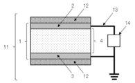
- FIG. 7 is a cross-sectional view illustrating one example of a structure of the electric generator of the present invention.
- the electric generator 11 illustrated in FIG. 7 includes an element 1, cover materials 12, electrical wires 13, and an electric circuit 14.
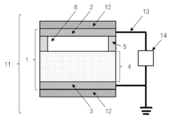
- FIG. 8 is a cross-sectional view illustrating another example of a structure of the electric generator of the present invention.
- a space 6 is disposed in the element 1 of the electric generator 11 illustrated in FIG. 8. Since the element 1 has the space 6, the element 1 has a structure that is easily deformed. Accordingly, a capacitance of the element changes even with weak vibrations to thereby increase a quantity of electricity generating. Examples
- Example 1 ⁇ Productions of Element and Electric Generator> -Production of Intermediate Layer- Silicone rubber (IVS4312, manufactured by Momentive Performance Materials Inc.) was applied onto a polyethylene terephthalate (PET) film, and the applied silicone rubber composition was heated to cure at 120°C for 30 minutes, to thereby form a thin film having a thickness of 100 ⁇ m. Subsequently, the thin film was subjected to a corona discharge treatment under the following conditions. Thereafter, the PET film was peeled. In the manner as described above, an intermediate layer was obtained. ⁇ Conditions of Corona Discharge> Applied voltage: 100 V Cumulative energy: 60 J/cm 2 Reaction atmosphere: air
- Rank B The value was 10 times or greater but less than 15 times, compared to Comparative Example 1, and the electricity generation performance is significantly improved.
- Rank C The value was 5 times or greater but less than 10 times, compared to Comparative Example 1, and the electricity generation performance is improved.
- Rank D The value was greater than 1 time but less than 15 times, compared to Comparative Example 1, and the electricity generation performance is slightly improved.
- Rank E The value was 1 time, compared to Comparative Example 1, and the electricity generation performance is identical.
- Rank F The value was less than 1 time, compared to Comparative Example 1, and the electricity generation performance is degraded.
- Example 2 ⁇ Productions of Element and Electric Generator> -Production of Intermediate Layer- Silicone rubber (KE-1935, manufactured by Shin-Etsu Chemical Co., Ltd.) was applied onto a polyethylene terephthalate (PET) film, and the applied silicone rubber composition was heated to cure at 120°C for 30 minutes, to thereby form a thin film having a thickness of 100 ⁇ m. Subsequently, the thin film was subjected to a corona discharge treatment in the same manner as in Example 1. Then, the PET film was peeled to thereby produce an intermediate layer of Example 2.
- PTT polyethylene terephthalate
- Example 2 Provides of Element and Electric Generator- An element and an electric generator of Example 2 were produced using the produced intermediate layer in the same manner as in Example 1.
- Example 2 ⁇ Evaluation> ⁇ Measurement of Infrared Absorption Spectrum>> The produced intermediate layer of Example 2 was subjected to a measurement of an infrared absorption spectrum in the same manner as in Example 1. As a result, the variation rate of the peak intensity ratio was 0.80. It was confirmed from the obtained variation rate that a region where a state of a Si-O-Si bond of the silicone rubber was different was present in the intermediate layer.
- Example 3 ⁇ Productions of Element and Electric Generator> -Production of Intermediate Layer-
- a silicone rubber composition was prepared by dispersing 100 parts by mass of silicone rubber (IVS4312, manufactured by Momentive Performance Materials Inc.), 50 parts by mass of barium titanate (208108, manufactured by Sigma-Aldrich Co., LLC.). Subsequently, the silicone rubber composition was applied onto a polyethylene terephthalate (PET) film, and the applied silicone rubber composition was heated to cure at 120°C for 30 minutes, to thereby form a thin film having a thickness of 100 ⁇ m. Subsequently, the thin film was subjected to a corona discharge treatment in the same manner as in Example 1. Then, the PET film was peeled to thereby produce an intermediate layer of Example 3.
- silicone rubber composition was prepared by dispersing 100 parts by mass of silicone rubber (IVS4312, manufactured by Momentive Performance Materials Inc.), 50 parts by mass of barium titanate (208108, manufactured by Sigma-Aldrich Co., LLC
- Example 3 Provides of Element and Electric Generator- An element and an electric generator of Example 3 were produced using the produced intermediate layer in the same manner as in Example 1.
- Example 3 ⁇ Evaluation> ⁇ Measurement of Infrared Absorption Spectrum>> The produced intermediate layer of Example 3 was subjected to a measurement of an infrared absorption spectrum in the same manner as in Example 1. As a result, the variation rate of the peak intensity ratio was 0.91. It was confirmed from the obtained variation rate that a region where a state of a Si-O-Si bond of the silicone rubber was different was present in the intermediate layer.
- Example 4 ⁇ Productions of Element and Electric Generator> -Production of Intermediate Layer-
- a silicone rubber composition was prepared by dispersing 100 parts by mass of silicone rubber (IVS4312, manufactured by Momentive Performance Materials Inc.), and 50 parts by mass of strontium titanate (396141, manufactured by Sigma-Aldrich Co., LLC.). Subsequently, the silicone rubber composition was applied onto a polyethylene terephthalate (PET) film, and the applied silicone rubber composition was heated to cure at 120°C for 30 minutes, to thereby form a thin film having a thickness of 100 ⁇ m. Subsequently, the thin film was subjected to a corona discharge treatment in the same manner as in Example 1. Then, the PET film was peeled to thereby produce an intermediate layer of Example 4.
- silicone rubber composition was prepared by dispersing 100 parts by mass of silicone rubber (IVS4312, manufactured by Momentive Performance Materials Inc.), and 50 parts by mass of strontium titanate (396141, manufactured by Sigma-Aldrich
- Example 4 Provides of Element and Electric Generator- An element and an electric generator of Example 4 were produced using the produced intermediate layer in the same manner as in Example 1.
- Example 4 ⁇ Evaluation> ⁇ Measurement of Infrared Absorption Spectrum>> The produced intermediate layer of Example 4 was subjected to a measurement of an infrared absorption spectrum in the same manner as in Example 1. As a result, the variation rate of the peak intensity ratio was 0.91. It was confirmed from the obtained variation rate that a region where a state of a Si-O-Si bond of the silicone rubber was different was present in the intermediate layer.
- Example 5 ⁇ Productions of Element and Electric Generator> -Production of Intermediate Layer-
- a silicone rubber composition was prepared by dispersing 100 parts by mass of silicone rubber (IVS4312, manufactured by Momentive Performance Materials Inc.), 10 parts by mass of silica (Sylysia 430, manufactured by Fuji Silysia Chemical Ltd.). Subsequently, the silicone rubber composition was applied onto a polyethylene terephthalate (PET) film, and the applied silicone rubber composition was heated to cure at 120°C for 30 minutes, to thereby form a thin film having a thickness of 200 ⁇ m.
- silicone rubber IVS4312, manufactured by Momentive Performance Materials Inc.
- silica Sylysia 430, manufactured by Fuji Silysia Chemical Ltd.
- the thin film was subjected to a plasma treatment (treatment conditions, a device for use: PR-500, manufactured by Yamato Scientific Co., Ltd., output: 100 W, processing time: 4 minutes, reaction atmosphere: argon 99.999%, reaction pressure: 10 Pa). Thereafter, the PET film was peeled. In the manner as described above, an intermediate layer was obtained.
- Example 5 ⁇ Evaluation> ⁇ Measurement of Infrared Absorption Spectrum>> The produced intermediate layer of Example 5 was subjected to a measurement of an infrared absorption spectrum in the same manner as in Example 1. As a result, the variation rate of the peak intensity ratio was 0.81. It was confirmed from the obtained variation rate that a region where a state of a Si-O-Si bond of the silicone rubber was different was present in the intermediate layer.
- Example 6 ⁇ Productions of Element and Electric Generator> -Production of Intermediate Layer, and Preparation of First Electrode and Second Electrode- An intermediate layer was produced, and a first electrode and a second electrode were prepared in the same manner as in Example 5.
- a space was disposed via a spacer (H10 LUMIRROR #500, manufactured by TORAY INDUSTRIES, INC., thickness of polyethylene terephthalate film: 480 ⁇ m) between the electrode and the surface of the intermediate layer at which the peak intensity ratio (1095 ⁇ 5 cm -1 /1025 ⁇ 5 cm -1 ) of the infrared absorption spectrum of the intermediate layer was larger.
- a spacer H10 LUMIRROR #500, manufactured by TORAY INDUSTRIES, INC., thickness of polyethylene terephthalate film: 480 ⁇ m
- Example 6 ⁇ Evaluation> ⁇ Measurement of Infrared Absorption Spectrum>> The produced intermediate layer of Example 6 was subjected to a measurement of an infrared absorption spectrum in the same manner as in Example 1. As a result, the variation rate of the peak intensity ratio was 0.81. It was confirmed from the obtained variation rate that a region where a state of a Si-O-Si bond of the silicone rubber was different was present in the intermediate layer.
- Example 7 ⁇ Productions of Element and Electric Generator> -Production of Intermediate Layer, and Preparation of First Electrode and Second Electrode- An intermediate layer was produced, and a first electrode and a second electrode were prepared in the same manner as in Example 5.
- a space was disposed via a spacer (H10 LUMIRROR #500, manufactured by TORAY INDUSTRIES, INC., thickness of polyethylene terephthalate film: 480 ⁇ m) between the electrode and the surface of the intermediate layer at which the peak intensity ratio (1095 ⁇ 5 cm -1 /1025 ⁇ 5 cm -1 ) of the infrared absorption spectrum of the intermediate layer was smaller.
- a spacer H10 LUMIRROR #500, manufactured by TORAY INDUSTRIES, INC., thickness of polyethylene terephthalate film: 480 ⁇ m
- Example 7 The produced intermediate layer of Example 7 was subjected to a measurement of an infrared absorption spectrum in the same manner as in Example 1. As a result, the variation rate of the peak intensity ratio was 0.81. It was confirmed from the obtained variation rate that a region where a state of a Si-O-Si bond of the silicone rubber was different was present in the intermediate layer.
- Example 8 ⁇ Productions of Element and Electric Generator> -Production of Intermediate Layer-
- a silicone rubber composition was prepared by dispersing 100 parts by mass of silicone rubber (IVS4312, manufactured by Momentive Performance Materials Inc.), and 50 parts by mass of silica (Sylysia 430, manufactured by Fuji Silysia Chemical Ltd.). Subsequently, the silicone rubber composition was applied onto a polyethylene terephthalate (PET) film, and the applied silicone rubber composition was heated to cure at 120°C for 30 minutes, to thereby form a thin film having a thickness of 200 ⁇ m. Subsequently, the thin film was subjected to a corona discharge treatment in the same manner as in Example 5. Then, the PET film was peeled to thereby produce an intermediate layer of Example 8.
- silicone rubber composition was prepared by dispersing 100 parts by mass of silicone rubber (IVS4312, manufactured by Momentive Performance Materials Inc.), and 50 parts by mass of silica (Sylysia 430, manufactured by
- Example 8 Provides of Element and Electric Generator- An element and an electric generator of Example 8 were produced using the produced intermediate layer in the same manner as in Example 7.
- Example 8 ⁇ Evaluation> ⁇ Measurement of Infrared Absorption Spectrum>> The produced intermediate layer of Example 8 was subjected to a measurement of an infrared absorption spectrum in the same manner as in Example 1. As a result, the variation rate of the peak intensity ratio was 0.87. It was confirmed from the obtained variation rate that a region where a state of a Si-O-Si bond of the silicone rubber was different was present in the intermediate layer.
- Example 9 ⁇ Productions of Element and Electric Generator> -Production of Intermediate Layer-
- a silicone rubber composition was prepared by dispersing 100 parts by mass of silicone rubber (IVS4312, manufactured by Momentive Performance Materials Inc.), and 60 parts by mass of silica (Sylysia 430, manufactured by Fuji Silysia Chemical Ltd.). Subsequently, the silicone rubber composition was applied onto a polyethylene terephthalate (PET) film, and the applied silicone rubber composition was heated to cure at 120°C for 30 minutes, to thereby form a thin film having a thickness of 200 ⁇ m. Subsequently, the thin film was subjected to a corona discharge treatment in the same manner as in Example 5. Then, the PET film was peeled to thereby produce an intermediate layer of Example 9.
- silicone rubber composition was prepared by dispersing 100 parts by mass of silicone rubber (IVS4312, manufactured by Momentive Performance Materials Inc.), and 60 parts by mass of silica (Sylysia 430, manufactured by
- Example 9 Provides of Element and Electric Generator- An element and an electric generator of Example 9 were produced using the produced intermediate layer in the same manner as in Example 7.
- Example 9 ⁇ Evaluation> ⁇ Measurement of Infrared Absorption Spectrum>> The produced intermediate layer of Example 9 was subjected to a measurement of an infrared absorption spectrum in the same manner as in Example 1. As a result, the variation rate of the peak intensity ratio was 0.88. It was confirmed from the obtained variation rate that a region where a state of a Si-O-Si bond of the silicone rubber was different was present in the intermediate layer.
- Example 10 ⁇ Productions of Element and Electric Generator> -Production of Intermediate Layer-
- a silicone rubber composition was prepared by dispersing 100 parts by mass of silicone rubber (IVS4312, manufactured by Momentive Performance Materials Inc.), and 10 parts by mass of silica (Sylysia 430, manufactured by Fuji Silysia Chemical Ltd.). Subsequently, the silicone rubber composition was applied onto a polyethylene terephthalate (PET) film, and the applied silicone rubber composition was heated to cure at 120°C for 30 minutes, to thereby form a thin film having a thickness of 20 ⁇ m. Subsequently, the thin film was subjected to a corona discharge treatment in the same manner as in Example 5. Then, the PET film was peeled to thereby produce an intermediate layer of Example 10.
- silicone rubber composition was prepared by dispersing 100 parts by mass of silicone rubber (IVS4312, manufactured by Momentive Performance Materials Inc.), and 10 parts by mass of silica (Sylysia 430, manufactured by
- Example 10 Provides of Element and Electric Generator- An element and an electric generator of Example 10 were produced using the produced intermediate layer in the same manner as in Example 7.
- Example 10 ⁇ Evaluation> ⁇ Measurement of Infrared Absorption Spectrum>> The produced intermediate layer of Example 10 was subjected to a measurement of an infrared absorption spectrum in the same manner as in Example 1. As a result, the variation rate of the peak intensity ratio was 0.82. It was confirmed from the obtained variation rate that a region where a state of a Si-O-Si bond of the silicone rubber was different was present in the intermediate layer.
- Example 11 ⁇ Productions of Element and Electric Generator> -Production of Intermediate Layer-
- a silicone rubber composition was prepared by dispersing 100 parts by mass of silicone rubber (IVS4312, manufactured by Momentive Performance Materials Inc.), and 10 parts by mass of silica (Sylysia 430, manufactured by Fuji Silysia Chemical Ltd.). Subsequently, the silicone rubber composition was applied onto a polyethylene terephthalate (PET) film, and the applied silicone rubber composition was heated to cure at 120°C for 30 minutes, to thereby form a thin film having a thickness of 300 ⁇ m. Subsequently, the thin film was subjected to a corona discharge treatment in the same manner as in Example 5. Then, the PET film was peeled to thereby produce an intermediate layer of Example 11.
- silicone rubber composition was prepared by dispersing 100 parts by mass of silicone rubber (IVS4312, manufactured by Momentive Performance Materials Inc.), and 10 parts by mass of silica (Sylysia 430, manufactured by
- Example 11 Provides of Element and Electric Generator- An element and an electric generator of Example 11 were produced using the produced intermediate layer in the same manner as in Example 7.
- Example 11 ⁇ Evaluation> ⁇ Measurement of Infrared Absorption Spectrum>> The produced intermediate layer of Example 11 was subjected to a measurement of an infrared absorption spectrum in the same manner as in Example 1. As a result, the variation rate of the peak intensity ratio was 0.80. It was confirmed from the obtained variation rate that a region where a state of a Si-O-Si bond of the silicone rubber was different was present in the intermediate layer.
- Example 12 ⁇ Productions of Element and Electric Generator> -Production of Intermediate Layer-
- a silicone rubber composition was prepared by dispersing 100 parts by mass of silicone rubber (IVS4312, manufactured by Momentive Performance Materials Inc.), and 50 parts by mass of silica (HS-207, manufactured by NIPPON STEEL & SUMIKIN MATERIALS Co., Ltd.). Subsequently, the silicone rubber composition was applied onto a polyethylene terephthalate (PET) film, and the applied silicone rubber composition was heated to cure at 120°C for 30 minutes, to thereby form a thin film having a thickness of 200 ⁇ m. Subsequently, the thin film was subjected to a corona discharge treatment in the same manner as in Example 5. Then, the PET film was peeled to thereby produce an intermediate layer of Example 12.
- silicone rubber composition was prepared by dispersing 100 parts by mass of silicone rubber (IVS4312, manufactured by Momentive Performance Materials Inc.), and 50 parts by mass of silica (HS-
- Example 12 Provides of Element and Electric Generator- An element and an electric generator of Example 12 were produced using the produced intermediate layer in the same manner as in Example 7.
- Example 12 ⁇ Evaluation> ⁇ Measurement of Infrared Absorption Spectrum>> The produced intermediate layer of Example 12 was subjected to a measurement of an infrared absorption spectrum in the same manner as in Example 1. As a result, the variation rate of the peak intensity ratio was 0.87. It was confirmed from the obtained variation rate that a region where a state of a Si-O-Si bond of the silicone rubber was different was present in the intermediate layer.
- Example 13 ⁇ Productions of Element and Electric Generator> -Production of Intermediate Layer-
- a silicone rubber composition was prepared by dispersing 100 parts by mass of silicone rubber (IVS4312, manufactured by Momentive Performance Materials Inc.), and 10 parts by mass of diatomaceous earth (CT-C499, manufactured by SHIRAISHI CALCIUM KAISHA, LTD.). Subsequently, the silicone rubber composition was applied onto a polyethylene terephthalate (PET) film, and the applied silicone rubber composition was heated to cure at 120°C for 30 minutes, to thereby form a thin film having a thickness of 200 ⁇ m. Subsequently, the thin film was subjected to a corona discharge treatment in the same manner as in Example 5. Then, the PET film was peeled to thereby produce an intermediate layer of Example 13.
- silicone rubber composition was prepared by dispersing 100 parts by mass of silicone rubber (IVS4312, manufactured by Momentive Performance Materials Inc.), and 10 parts by mass of diatomaceous earth (CT-C499
- Example 13 Provides of Element and Electric Generator- An element and an electric generator of Example 13 were produced using the produced intermediate layer in the same manner as in Example 7.
- Example 13 was subjected to a measurement of an infrared absorption spectrum in the same manner as in Example 1. As a result, the variation rate of the peak intensity ratio was 0.84. It was confirmed from the obtained variation rate that a region where a state of a Si-O-Si bond of the silicone rubber was different was present in the intermediate layer.
- Example 14 ⁇ Productions of Element and Electric Generator> -Production of Intermediate Layer-
- a silicone rubber composition was prepared by dispersing 100 parts by mass of silicone rubber (TSE3033, manufactured by Momentive Performance Materials Inc.), and 5 parts by mass of kaolin (Glomax LL, manufactured by TAKEHARA KAGAKU KOGYO CO., LTD.). Subsequently, the silicone rubber composition was applied onto a polyethylene terephthalate (PET) film, and the applied silicone rubber composition was heated to cure at 120°C for 30 minutes, to thereby form a thin film having a thickness of 150 ⁇ m.
- PET polyethylene terephthalate
- Example 14 An intermediate layer of Example 14 was obtained.
- Example 14 was subjected to a measurement of an infrared absorption spectrum in the same manner as in Example 1. As a result, the variation rate of the peak intensity ratio was 0.78. It was confirmed from the obtained variation rate that a region where a state of a Si-O-Si bond of the silicone rubber was different was present in the intermediate layer.
- Example 15 ⁇ Productions of Element and Electric Generator> -Production of Intermediate Layer, and Preparation of First Electrode and Second Electrode- An intermediate layer was produced, and a first electrode and a second electrode were prepared in the same manner as in Example 14.
- a space was disposed via a spacer (H10 LUMIRROR #500, manufactured by TORAY INDUSTRIES, INC., thickness of polyethylene terephthalate film: 480 ⁇ m) between the electrode and the surface of the intermediate layer at which the peak intensity ratio (1095 ⁇ 5 cm -1 /1025 ⁇ 5 cm -1 ) of the infrared absorption spectrum of the intermediate layer was larger.
- a spacer H10 LUMIRROR #500, manufactured by TORAY INDUSTRIES, INC., thickness of polyethylene terephthalate film: 480 ⁇ m
- Example 15 was subjected to a measurement of an infrared absorption spectrum in the same manner as in Example 1. As a result, the variation rate of the peak intensity ratio was 0.78. It was confirmed from the obtained variation rate that a region where a state of a Si-O-Si bond of the silicone rubber was different was present in the intermediate layer.
- Example 16 ⁇ Productions of Element and Electric Generator> -Production of Intermediate Layer, and Preparation of First Electrode and Second Electrode- An intermediate layer was produced, and a first electrode and a second electrode were prepared in the same manner as in Example 14.
- a space was disposed via a spacer (H10 LUMIRROR #500, manufactured by TORAY INDUSTRIES, INC., thickness of polyethylene terephthalate film: 480 ⁇ m) between the electrode and the surface of the intermediate layer at which the peak intensity ratio (1095 ⁇ 5 cm -1 /1025 ⁇ 5 cm -1 ) of the infrared absorption spectrum of the intermediate layer was smaller.
- a spacer H10 LUMIRROR #500, manufactured by TORAY INDUSTRIES, INC., thickness of polyethylene terephthalate film: 480 ⁇ m
- Example 16 was subjected to a measurement of an infrared absorption spectrum in the same manner as in Example 1. As a result, the variation rate of the peak intensity ratio was 0.78. It was confirmed from the obtained variation rate that a region where a state of a Si-O-Si bond of the silicone rubber was different was present in the intermediate layer.
- Example 17 ⁇ Productions of Element and Electric Generator> -Production of Intermediate Layer-
- a silicone rubber composition was prepared by dispersing 100 parts by mass of silicone rubber (TSE3033, manufactured by Momentive Performance Materials Inc.), and 1 part by mass of kaolin (Glomax LL, manufactured by TAKEHARA KAGAKU KOGYO CO., LTD.). Subsequently, the silicone rubber composition was applied onto a polyethylene terephthalate (PET) film, and the applied silicone rubber composition was heated to cure at 120°C for 30 minutes, to thereby form a thin film having a thickness of 150 ⁇ m. Subsequently, the thin film was subjected to a corona discharge treatment in the same manner as in Example 14. Then, the PET film was peeled to thereby produce an intermediate layer of Example 17.
- silicone rubber composition was prepared by dispersing 100 parts by mass of silicone rubber (TSE3033, manufactured by Momentive Performance Materials Inc.), and 1 part by mass of kaolin (Glomax LL,
- Example 17 Provides of Element and Electric Generator- An element and an electric generator of Example 17 were produced using the produced intermediate layer in the same manner as in Example 16.
- Example 17 was subjected to a measurement of an infrared absorption spectrum in the same manner as in Example 1. As a result, the variation rate of the peak intensity ratio was 0.73. It was confirmed from the obtained variation rate that a region where a state of a Si-O-Si bond of the silicone rubber was different was present in the intermediate layer.
- Example 18 ⁇ Productions of Element and Electric Generator> -Production of Intermediate Layer-
- a silicone rubber composition was prepared by dispersing 100 parts by mass of silicone rubber (TSE3033, manufactured by Momentive Performance Materials Inc.), and 60 parts by mass of kaolin (Glomax LL, manufactured by TAKEHARA KAGAKU KOGYO CO., LTD.). Subsequently, the silicone rubber composition was applied onto a polyethylene terephthalate (PET) film, and the applied silicone rubber composition was heated to cure at 120°C for 30 minutes, to thereby form a thin film having a thickness of 150 ⁇ m. Subsequently, the thin film was subjected to a corona discharge treatment in the same manner as in Example 14. Then, the PET film was peeled to thereby produce an intermediate layer of Example 18.
- Example 18 Provides of Element and Electric Generator- An element and an electric generator of Example 18 were produced using the produced intermediate layer in the same manner as in Example 16.
- Example 18 was subjected to a measurement of an infrared absorption spectrum in the same manner as in Example 1. As a result, the variation rate of the peak intensity ratio was 0.85. It was confirmed from the obtained variation rate that a region where a state of a Si-O-Si bond of the silicone rubber was different was present in the intermediate layer.
- Example 19 ⁇ Productions of Element and Electric Generator> -Production of Intermediate Layer-
- a silicone rubber composition was prepared by dispersing 100 parts by mass of silicone rubber (TES3033, manufactured by Momentive Performance Materials Inc.), and 5 parts by mass of kaolin (Glomax LL, manufactured by TAKEHARA KAGAKU KOGYO CO., LTD.). Subsequently, the silicone rubber composition was applied onto a polyethylene terephthalate (PET) film, and the applied silicone rubber composition was heated to cure at 120°C for 30 minutes, to thereby form a thin film having a thickness of 20 ⁇ m. Subsequently, the thin film was subjected to a corona discharge treatment in the same manner as in Example 14. Then, the PET film was peeled to thereby produce an intermediate layer of Example 19.
- silicone rubber composition was prepared by dispersing 100 parts by mass of silicone rubber (TES3033, manufactured by Momentive Performance Materials Inc.), and 5 parts by mass of kaolin (Glomax LL, manufactured by
- Example 19 Provides of Element and Electric Generator- An element and an electric generator of Example 19 were produced using the produced intermediate layer in the same manner as in Example 16.
- Example 19 was subjected to a measurement of an infrared absorption spectrum in the same manner as in Example 1. As a result, the variation rate of the peak intensity ratio was 0.80. It was confirmed from the obtained variation rate that a region where a state of a Si-O-Si bond of the silicone rubber was different was present in the intermediate layer.
- Example 20 ⁇ Productions of Element and Electric Generator> -Production of Intermediate Layer-
- a silicone rubber composition was prepared by dispersing 100 parts by mass of silicone rubber (TES3033, manufactured by Momentive Performance Materials Inc.), and 5 parts by mass of kaolin (Glomax LL, manufactured by TAKEHARA KAGAKU KOGYO CO., LTD.). Subsequently, the silicone rubber composition was applied onto a polyethylene terephthalate (PET) film, and the applied silicone rubber composition was heated to cure at 120°C for 30 minutes, to thereby form a thin film having a thickness of 300 ⁇ m. Subsequently, the thin film was subjected to a corona discharge treatment in the same manner as in Example 14. Then, the PET film was peeled to thereby produce an intermediate layer of Example 20.
- silicone rubber composition was prepared by dispersing 100 parts by mass of silicone rubber (TES3033, manufactured by Momentive Performance Materials Inc.), and 5 parts by mass of kaolin (Glomax LL, manufactured
- Example 20 Provides of Element and Electric Generator- An element and an electric generator of Example 20 were produced using the produced intermediate layer in the same manner as in Example 16.
- Example 20 was subjected to a measurement of an infrared absorption spectrum in the same manner as in Example 1. As a result, the variation rate of the peak intensity ratio was 0.77. It was confirmed from the obtained variation rate that a region where a state of a Si-O-Si bond of the silicone rubber was different was present in the intermediate layer.
- Example 21 ⁇ Productions of Element and Electric Generator> -Production of Intermediate Layer-
- a first silicone rubber composition was prepared by dispersing 100 parts by mass of silicone rubber (XE14-C2042, manufactured by Momentive Performance Materials Inc.), and 5 parts by mass of kaolin (Glomax LL, manufactured by TAKEHARA KAGAKU KOGYO CO., LTD.). Subsequently, the first silicone rubber composition was applied onto a polyimide film, and the applied silicone rubber composition was heated to cure at 120°C for 30 minutes, to thereby form a first thin film having a thickness of 100 ⁇ m.
- a second silicone rubber composition was prepared by dispersing 100 parts by mass of silicone rubber (XE14-C2042, manufactured by Momentive Performance Materials Inc.), and 20 parts by mass of kaolin (RC-1, manufactured by TAKEHARA KAGAKU KOGYO CO., LTD.). Subsequently, the second silicone rubber composition was applied onto the first thin film, and the applied second silicone rubber composition was heated to cure at 120°C for 30 minutes, to thereby form a second thin film having a thickness of 100 ⁇ m. After heating the first thin film and the second thin film at 200°C for 5 hours, the polyimide film was peeled to thereby produce an intermediate layer of Example 21. Note that, a surface modification treatment was not performed.
- a space was disposed via a spacer (ether-based urethane rubber FH sheet, manufactured by Fuso Rubber Industry Co., Ltd., thickness of rubber sheet: 1 mm) between the electrode and the surface of the intermediate layer at which the peak intensity ratio (1095 ⁇ 5 cm -1 /1025 ⁇ 5 cm -1 ) of the infrared absorption spectrum of the intermediate layer was smaller.
- a spacer ether-based urethane rubber FH sheet, manufactured by Fuso Rubber Industry Co., Ltd., thickness of rubber sheet: 1 mm
- Example 21 was subjected to a measurement of an infrared absorption spectrum in the same manner as in Example 1. As a result, the variation rate of the peak intensity ratio was 0.95. It was confirmed from the obtained variation rate that a region where a state of a Si-O-Si bond of the silicone rubber was different was present in the intermediate layer.
- Example 22 ⁇ Productions of Element and Electric Generator> -Production of Intermediate Layer- Silicone rubber (XE14-C2042, manufactured by Momentive Performance Materials Inc.) was applied onto a polyimide film, and the applied silicone rubber was heated to cure at 120°C for 30 minutes, to thereby form a first thin film having a thickness of 100 ⁇ m. Subsequently, a second silicone rubber composition was prepared by dispersing 100 parts by mass of silicone rubber (XE14-C2042, manufactured by Momentive Performance Materials Inc.), and 50 parts by mass of kaolin (ST-CROWN, manufactured by SHIRAISHI CALCIUM KAISHA, LTD.).
- the second silicone rubber composition was applied onto the first thin film, and the applied second silicone rubber composition was heated to cure at 120°C for 30 minutes, to thereby form a second thin film having a thickness of 100 ⁇ m.
- the polyimide film was peeled to thereby produce an intermediate layer of Example 22. Note that, a surface modification treatment was not performed.
- Example 22 Provides of Element and Electric Generator- An element and an electric generator of Example 22 were produced using the produced intermediate layer in the same manner as in Example 21.
- Example 22 ⁇ Evaluation> ⁇ Measurement of Infrared Absorption Spectrum>> The produced intermediate layer of Example 22 was subjected to a measurement of an infrared absorption spectrum in the same manner as in Example 1. As a result, the variation rate of the peak intensity ratio was 0.94. It was confirmed from the obtained variation rate that a region where a state of a Si-O-Si bond of the silicone rubber was different was present in the intermediate layer.
- Example 23 ⁇ Productions of Element and Electric Generator> -Production of Intermediate Layer-
- a silicone rubber composition was prepared by dispersing 100 parts by mass of silicone rubber (TES3033, manufactured by Momentive Performance Materials Inc.), and 10 parts by mass of talc (Microlite manufactured by TAKEHARA KAGAKU KOGYO CO., LTD.). Subsequently, the silicone rubber composition was applied onto a polyethylene terephthalate (PET) film, and the applied silicone rubber composition was heated to cure at 120°C for 30 minutes, to thereby form a thin film having a thickness of 150 ⁇ m. Subsequently, the thin film was subjected to a corona discharge treatment in the same manner as in Example 1. Then, the PET film was peeled to thereby produce an intermediate layer of Example 23.
- silicone rubber composition was prepared by dispersing 100 parts by mass of silicone rubber (TES3033, manufactured by Momentive Performance Materials Inc.), and 10 parts by mass of talc (Microlite manufactured by TAKEHARA
- Example 23 Provides of Element and Electric Generator- An element and an electric generator of Example 23 were produced using the produced intermediate layer in the same manner as in Example 7.
- Example 23 was subjected to a measurement of an infrared absorption spectrum in the same manner as in Example 1. As a result, the variation rate of the peak intensity ratio was 0.82. It was confirmed from the obtained variation rate that a region where a state of a Si-O-Si bond of the silicone rubber was different was present in the intermediate layer.
- Example 24 ⁇ Productions of Element and Electric Generator> -Production of Intermediate Layer- Silicone rubber (XE14-C2042, manufactured by Momentive Performance Materials Inc.) was applied onto a polyethylene terephthalate (PET) film, and the applied silicone rubber was heated to cure at 120°C for 30 minutes, to thereby form a first thin film having a thickness of 100 ⁇ m. Subsequently, a second silicone rubber composition was prepared by dispersing 100 parts by mass of silicone rubber (XE14-C2042, manufactured by Momentive Performance Materials Inc.), and 10 parts by mass of talc (D-1000, manufactured by NIPPON TALC Co., Ltd.).
- Example 24 the second silicone rubber composition was applied onto the first thin film, and the applied second silicone rubber composition was heated to cure at 120°C for 30 minutes, to thereby form a second thin film having a thickness of 100 ⁇ m. Subsequently, the first thin film and the second thin film were subjected to a corona discharge treatment in the same manner as in Example 1. The PET film was the peeled, to thereby produce an intermediate layer of Example 24.
- Example 24 Provides of Element and Electric Generator- An element and an electric generator of Example 24 were produced using the produced intermediate layer in the same manner as in Example 21.
- Example 24 was subjected to a measurement of an infrared absorption spectrum in the same manner as in Example 1. As a result, the variation rate of the peak intensity ratio was 0.88. It was confirmed from the obtained variation rate that a region where a state of a Si-O-Si bond of the silicone rubber was different was present in the intermediate layer.
- Example 25 ⁇ Productions of Element and Electric Generator> -Production of Intermediate Layer-
- a silicone rubber composition was prepared by dispersing 100 parts by mass of silicone rubber (TSE3033, manufactured by Momentive Performance Materials Inc.), and 10 parts by mass of wollastonite (ST-40F, manufactured by SHIRAISHI CALCIUM KAISHA, LTD.). Subsequently, the silicone rubber composition was applied onto a polyethylene terephthalate (PET) film, and the applied silicone rubber composition was heated to cure at 120°C for 30 minutes, to thereby form a thin film having a thickness of 100 ⁇ m.
- PET polyethylene terephthalate
- the thin film was subjected to an electron-beam irradiation treatment (treatment conditions, device for use: line-irradiation low-energy electron beam light source, manufactured by Hamamatsu Photonics K.K., radiation dose: 1 MGy, reaction atmosphere: nitrogen with oxygen partial pressure of 5,000 ppm or less). Thereafter, the PET film was peeled, to thereby produce an intermediate layer of Example 25.
- treatment conditions device for use: line-irradiation low-energy electron beam light source, manufactured by Hamamatsu Photonics K.K., radiation dose: 1 MGy, reaction atmosphere: nitrogen with oxygen partial pressure of 5,000 ppm or less.
- the obtained intermediate layer 25 was sandwiched with electrodes (conductive cloth Sui-80-M30 manufactured by SEIREN Co., Ltd., thickness of non-woven fabric plated with copper and nickel: 35 ⁇ m), and a lead wire (C3/RV-90 0.75SQ, manufactured by Taiyo Cabletec Corporation) was attached to the assembly.
- the resultant was further sandwiched with cover materials (SLF-PP01G, manufactured by EUROPORT, thickness of polypropylene film: 20 ⁇ m), to thereby produce an element.
- a space was disposed via a spacer (H10 LUMIRROR #500, manufactured by TORAY INDUSTRIES, INC., thickness of polyethylene terephthalate film: 480 ⁇ m) between the electrode and the surface of the intermediate layer 25 at which the peak intensity ratio (1095 ⁇ 5 cm -1 /1025 ⁇ 5 cm -1 ) of the infrared absorption spectrum of the intermediate layer was smaller.
- a spacer H10 LUMIRROR #500, manufactured by TORAY INDUSTRIES, INC., thickness of polyethylene terephthalate film: 480 ⁇ m
- Oscilloscope (WaveAce1001, manufactured by Teledyne LeCroy Japan Corporation) was attached to the obtained element, to thereby produce an electric generator of Example 25.
- Example 25 was subjected to a measurement of an infrared absorption spectrum in the same manner as in Example 1. As a result, the variation rate of the peak intensity ratio was 0.78. It was confirmed from the obtained variation rate that a region where a state of a Si-O-Si bond of the silicone rubber was different was present in the intermediate layer.
- Example 26 ⁇ Productions of Element and Electric Generator> -Production of Intermediate Layer-
- a silicone rubber composition was prepared by dispersing 100 parts by mass of silicone rubber (TSE3033, manufactured by Momentive Performance Materials Inc.), and 10 parts by mass of wollastonite (Wollasto JET30w, manufactured by Asada Milling Co., Ltd.). Subsequently, the silicone rubber composition was applied onto a polyethylene terephthalate (PET) film, and the applied silicone rubber composition was heated to cure at 120°C for 30 minutes, to thereby form a thin film having a thickness of 100 ⁇ m. Subsequently, the thin film was subjected to an electron-beam irradiation treatment in the same manner as in Example 25. Then, the PET film was peeled to thereby produce an intermediate layer of Example 26.
- silicone rubber composition was prepared by dispersing 100 parts by mass of silicone rubber (TSE3033, manufactured by Momentive Performance Materials Inc.), and 10 parts by mass of wollastonite (
- Example 26 Provides of Element and Electric Generator- An element and an electric generator of Example 26 were produced using the produced intermediate layer in the same manner as in Example 25.
- Example 26 was subjected to a measurement of an infrared absorption spectrum in the same manner as in Example 1. As a result, the variation rate of the peak intensity ratio was 0.78. It was confirmed from the obtained variation rate that a region where a state of a Si-O-Si bond of the silicone rubber was different was present in the intermediate layer.
- Example 27 ⁇ Productions of Element and Electric Generator> -Production of Intermediate Layer-
- a silicone rubber composition was prepared by dispersing 100 parts by mass of silicone rubber (TES3033, manufactured by Momentive Performance Materials Inc.), and 20 parts by mass of mica (A-11, manufactured by YAMAGUCHI MICA CO., LTD.). Subsequently, the silicone rubber composition was applied onto a polyethylene terephthalate (PET) film, and the applied silicone rubber composition was heated to cure at 120°C for 30 minutes, to thereby form a thin film having a thickness of 100 ⁇ m. Subsequently, the thin film was subjected to a plasma treatment in the same manner as in Example 5. Then, the PET film was peeled to thereby produce an intermediate layer of Example 27.
- silicone rubber composition was prepared by dispersing 100 parts by mass of silicone rubber (TES3033, manufactured by Momentive Performance Materials Inc.), and 20 parts by mass of mica (A-11, manufactured by YAMAGUCHI MICA CO., LTD.). Subsequently,
- Example 27 Provides of Element and Electric Generator- An element and an electric generator of Example 27 were produced using the produced intermediate layer in the same manner as in Example 25.
- Example 27 The produced intermediate layer of Example 27 was subjected to a measurement of an infrared absorption spectrum in the same manner as in Example 1. As a result, the variation rate of the peak intensity ratio was 0.93. It was confirmed from the obtained variation rate that a region where a state of a Si-O-Si bond of the silicone rubber was different was present in the intermediate layer.
- Example 28 ⁇ Productions of Element and Electric Generator> -Production of Intermediate Layer-
- a silicone rubber composition was prepared by dispersing 100 parts by mass of silicone rubber (TSE3033, manufactured by Momentive Performance Materials Inc.), and 20 parts by mass of zeolite (SP#2300, manufactured by NITTO FUNKA KOGYO K.K.). Subsequently, the silicone rubber composition was applied onto a polyethylene terephthalate (PET) film, and the applied silicone rubber composition was heated to cure at 120°C for 30 minutes, to thereby form a thin film having a thickness of 100 ⁇ m. Subsequently, the thin film was subjected to a plasma treatment in the same manner as in Example 5. Then, the PET film was peeled to thereby produce an intermediate layer of Example 28.
- TSE3033 manufactured by Momentive Performance Materials Inc.
- SP#2300 manufactured by NITTO FUNKA KOGYO K.K.
- Example 28 Provides of Element and Electric Generator- An element and an electric generator of Example 28 were produced using the produced intermediate layer in the same manner as in Example 25.
- Example 28 was subjected to a measurement of an infrared absorption spectrum in the same manner as in Example 1. As a result, the variation rate of the peak intensity ratio was 0.92. It was confirmed from the obtained variation rate that a region where a state of a Si-O-Si bond of the silicone rubber was different was present in the intermediate layer.
- Example 29 ⁇ Productions of Element and Electric Generator> -Production of Intermediate Layer-
- a silicone rubber composition was prepared by dispersing 100 parts by mass of silicone rubber (TES3033, manufactured by Momentive Performance Materials Inc.), and 20 parts by mass of sericite (ST-501, manufactured by SHIRAISHI CALCIUM KAISHA, LTD.). Subsequently, the silicone rubber composition was applied onto a polyethylene terephthalate (PET) film, and the applied silicone rubber composition was heated to cure at 120°C for 30 minutes, to thereby form a thin film having a thickness of 100 ⁇ m. Subsequently, the thin film was subjected to a plasma treatment in the same manner as in Example 5. Then, the PET film was peeled to thereby produce an intermediate layer of Example 29.
- silicone rubber composition was prepared by dispersing 100 parts by mass of silicone rubber (TES3033, manufactured by Momentive Performance Materials Inc.), and 20 parts by mass of sericite (ST-501, manufactured by SHIRAISHI CALCIUM KAISHA
- Example 29 Provides of Element and Electric Generator- An element and an electric generator of Example 29 were produced using the produced intermediate layer in the same manner as in Example 25.
- Example 29 was subjected to a measurement of an infrared absorption spectrum in the same manner as in Example 1. As a result, the variation rate of the peak intensity ratio was 0.90. It was confirmed from the obtained variation rate that a region where a state of a Si-O-Si bond of the silicone rubber was different was present in the intermediate layer.
- Example 30 ⁇ Productions of Element and Electric Generator> -Production of Intermediate Layer-
- a silicone rubber composition was prepared by dispersing 100 parts by mass of silicone rubber (KE-1935, manufactured by Shin-Etsu Chemical Co., Ltd.), and 20 parts by mass of hollow glass beads (Sphericel 110P8, manufactured by Potters-Ballotini Co., Ltd.). Subsequently, the silicone rubber composition was applied onto a polyethylene terephthalate (PET) film, and the applied silicone rubber composition was heated to cure at 120°C for 30 minutes, to thereby form a thin film having a thickness of 100 ⁇ m. Subsequently, the thin film was subjected to a plasma treatment in the same manner as in Example 5. Then, the PET film was peeled to thereby produce an intermediate layer of Example 30.
- silicone rubber composition was prepared by dispersing 100 parts by mass of silicone rubber (KE-1935, manufactured by Shin-Etsu Chemical Co., Ltd.), and 20 parts by mass of hollow glass beads (
- Example 30 Provides of Element and Electric Generator- An element and an electric generator of Example 30 were produced using the produced intermediate layer in the same manner as in Example 25.
- Example 30 was subjected to a measurement of an infrared absorption spectrum in the same manner as in Example 1. As a result, the variation rate of the peak intensity ratio was 0.90. It was confirmed from the obtained variation rate that a region where a state of a Si-O-Si bond of the silicone rubber was different was present in the intermediate layer.
- Example 31 ⁇ Productions of Element and Electric Generator> -Production of Intermediate Layer-
- a silicone rubber composition was prepared by dispersing 100 parts by mass of silicone rubber (KE-1935, manufactured by Shin-Etsu Chemical Co., Ltd.), and 20 parts by mass of acryl particles (FH-S005, manufactured by TOYOBO CO., LTD.). Subsequently, the silicone rubber composition was applied onto a polyethylene terephthalate (PET) film, and the applied silicone rubber composition was heated to cure at 120°C for 30 minutes, to thereby form a thin film having a thickness of 100 ⁇ m. Subsequently, the thin film was subjected to a plasma treatment in the same manner as in Example 5. Then, the PET film was peeled to thereby produce an intermediate layer of Example 31.
- silicone rubber composition was prepared by dispersing 100 parts by mass of silicone rubber (KE-1935, manufactured by Shin-Etsu Chemical Co., Ltd.), and 20 parts by mass of acryl particles (FH-S005,
- Example 31 Provides of Element and Electric Generator- An element and an electric generator of Example 31 were produced using the produced intermediate layer in the same manner as in Example 25.
- Example 31 ⁇ Evaluation> ⁇ Measurement of Infrared Absorption Spectrum>> The produced intermediate layer of Example 31 was subjected to a measurement of an infrared absorption spectrum in the same manner as in Example 1. As a result, the variation rate of the peak intensity ratio was 0.95. It was confirmed from the obtained variation rate that a region where a state of a Si-O-Si bond of the silicone rubber was different was present in the intermediate layer.
- Example 32 ⁇ Productions of Element and Electric Generator> -Production of Intermediate Layer-
- a silicone rubber composition was prepared by dispersing 100 parts by mass of silicone rubber (KE-1935, manufactured by Shin-Etsu Chemical Co., Ltd.), and 20 parts by mass of polystyrene particles (19520-500, manufactured by Techno Chemical Corporation). Subsequently, the silicone rubber composition was applied onto a polyethylene terephthalate (PET) film, and the applied silicone rubber composition was heated to cure at 120°C for 30 minutes, to thereby form a thin film having a thickness of 100 ⁇ m. Subsequently, the thin film was subjected to a plasma treatment in the same manner as in Example 5. Then, the PET film was peeled to thereby produce an intermediate layer of Example 32.
- silicone rubber composition was prepared by dispersing 100 parts by mass of silicone rubber (KE-1935, manufactured by Shin-Etsu Chemical Co., Ltd.), and 20 parts by mass of polystyrene particles (19520-500, manufactured by
- Example 32 Provides of Element and Electric Generator- An element and an electric generator of Example 32 were produced using the produced intermediate layer in the same manner as in Example 25.
- Example 32 was subjected to a measurement of an infrared absorption spectrum in the same manner as in Example 1. As a result, the variation rate of the peak intensity ratio was 0.95. It was confirmed from the obtained variation rate that a region where a state of a Si-O-Si bond of the silicone rubber was different was present in the intermediate layer.
- Example 33 ⁇ Productions of Element and Electric Generator> -Production of Intermediate Layer-
- a silicone rubber composition was prepared by dispersing 100 parts by mass of silicone rubber (XE14-C2042, manufactured by Momentive Performance Materials Inc.), and 50 parts by mass of silica (HS-207, manufactured by NIPPON STEEL & SUMIKIN MATERIALS Co., Ltd.). Subsequently, the silicone rubber composition was applied onto a polyethylene terephthalate (PET) film, and the applied silicone rubber composition was heated to cure at 120°C for 30 minutes, to thereby form a first thin film having a thickness of 50 ⁇ m.
- PET polyethylene terephthalate
- silicone rubber (XE14-C2042, manufactured by Momentive Performance Materials Inc.) was applied onto the first thin film, and the applied silicone rubber was heated to cure at 120°C for 30 minutes, to thereby form a second thin film having a thickness of 50 ⁇ m.
- the first thin film and the second thin film were subjected to an electron-beam irradiation treatment in the same manner as in Example 25. Then, the PET film was peeled to thereby produce an intermediate layer of Example 33.
- a first electrode AL-PET 20-100 (thickness of aluminium foil: 20 ⁇ m, thickness of polyethylene terephthalate film: 100 ⁇ m (cover material)) manufactured by PANAC CO., LTD. was provided.
- a second electrode Panabrid 35-50 (thickness of copper foil: 35 ⁇ m, thickness of polyethylene terephthalate film: 50 ⁇ m (cover material)) manufactured by PANAC CO., LTD. was provided.
- Example 33 was subjected to a measurement of an infrared absorption spectrum in the same manner as in Example 1. As a result, the variation rate of the peak intensity ratio was 0.81. It was confirmed from the obtained variation rate that a region where a state of a Si-O-Si bond of the silicone rubber was different was present in the intermediate layer.
- Example 34 ⁇ Productions of Element and Electric Generator> -Production of Intermediate Layer-
- a silicone rubber composition was prepared by dispersing 100 parts by mass of silicone rubber (XE14-C2042, manufactured by Momentive Performance Materials Inc.), and 50 parts by mass of wollastonite (Wollasto JET30w, manufactured by Asada Milling Co., Ltd.). Subsequently, the silicone rubber composition was applied onto a polyethylene terephthalate (PET) film, and the applied silicone rubber composition was heated to cure at 120°C for 30 minutes, to thereby form a first thin film having a thickness of 50 ⁇ m.
- PET polyethylene terephthalate
- silicone rubber (XE14-C2042, manufactured by Momentive Performance Materials Inc.) was applied onto the first thin film, and the applied silicone rubber was heated to cure at 120°C for 30 minutes, to thereby form a second thin film having a thickness of 50 ⁇ m.
- the first thin film and the second thin film were subjected to an electron-beam irradiation treatment in the same manner as in Example 25. Then, the PET film was peeled to thereby produce an intermediate layer of Example 34.
- Example 34 Provides of Element and Electric Generator- An element and an electric generator of Example 34 were produced using the produced intermediate layer in the same manner as in Example 33.
- Example 34 ⁇ Evaluation> ⁇ Measurement of Infrared Absorption Spectrum>> The produced intermediate layer of Example 34 was subjected to a measurement of an infrared absorption spectrum in the same manner as in Example 1. As a result, the variation rate of the peak intensity ratio was 0.81. It was confirmed from the obtained variation rate that a region where a state of a Si-O-Si bond of the silicone rubber was different was present in the intermediate layer.
- Example 35 ⁇ Productions of Element and Electric Generator> -Production of Intermediate Layer-
- a silicone rubber composition was prepared by dispersing 100 parts by mass of silicone rubber (KE-1935, manufactured by Shin-Etsu Chemical Co., Ltd.), 20 parts by mass of a silicone resin powder (Tospearl 120, manufactured by Momentive Performance Materials Inc.). Subsequently, the silicone rubber composition was applied onto a polyethylene terephthalate (PET) film, and the applied silicone rubber composition was heated to cure at 120°C for 30 minutes, to thereby form a thin film having a thickness of 100 ⁇ m. Subsequently, the thin film was subjected to a plasma treatment in the same manner as in Example 5. Then, the PET film was peeled to thereby produce an intermediate layer of Example 35.
- silicone rubber KE-1935, manufactured by Shin-Etsu Chemical Co., Ltd.
- Tospearl 120 manufactured by Momentive Performance Materials Inc.
- Example 35 Provides of Element and Electric Generator- An element and an electric generator of Example 35 were produced using the produced intermediate layer in the same manner as in Example 33.
- Example 35 was subjected to a measurement of an infrared absorption spectrum in the same manner as in Example 1. As a result, the variation rate of the peak intensity ratio was 0.83. It was confirmed from the obtained variation rate that a region where a state of a Si-O-Si bond of the silicone rubber was different was present in the intermediate layer.
- Example 36 ⁇ Productions of Element and Electric Generator> -Production of Intermediate Layer-
- a silicone rubber composition was prepared by dispersing 100 parts by mass of silicone rubber (KE-1935, manufactured by Shin-Etsu Chemical Co., Ltd.), and 20 parts by mass of a silicone rubber powder (EP-2600, manufactured by Dow Corning Toray Co., Ltd.). Subsequently, the silicone rubber composition was applied onto a polyethylene terephthalate (PET) film, and the applied silicone rubber composition was heated to cure at 120°C for 30 minutes, to thereby form a thin film having a thickness of 100 ⁇ m. Subsequently, the thin film was subjected to a plasma treatment in the same manner as in Example 5. Then, the PET film was peeled, to thereby produce an intermediate layer of Example 36.
- silicone rubber composition was prepared by dispersing 100 parts by mass of silicone rubber (KE-1935, manufactured by Shin-Etsu Chemical Co., Ltd.), and 20 parts by mass of a silicone rubber powder (EP-2
- Example 36 Provides of Element and Electric Generator- An element and an electric generator of Example 36 were produced using the produced intermediate layer in the same manner as in Example 33.
- Example 36 was subjected to a measurement of an infrared absorption spectrum in the same manner as in Example 1. As a result, the variation rate of the peak intensity ratio was 0.83. It was confirmed from the obtained variation rate that a region where a state of a Si-O-Si bond of the silicone rubber was different was present in the intermediate layer.
- Example 37 ⁇ Productions of Element and Electric Generator> -Production of Intermediate Layer-
- a silicone rubber composition was prepared by dispersing 100 parts by mass of silicone rubber (KE-1935, manufactured by Shin-Etsu Chemical Co., Ltd.), and 20 parts by mass of a silicone composite powder (KMP-605, manufactured by Shin-Etsu Chemical Co., Ltd.). Subsequently, the silicone rubber composition was applied onto a polyethylene terephthalate (PET) film, and the applied silicone rubber composition was heated to cure at 120°C for 30 minutes, to thereby form a thin film having a thickness of 100 ⁇ m. Subsequently, the thin film was subjected to a plasma treatment in the same manner as in Example 5. Then, the PET film was peeled to thereby produce an intermediate layer of Example 37.
- silicone rubber composition was prepared by dispersing 100 parts by mass of silicone rubber (KE-1935, manufactured by Shin-Etsu Chemical Co., Ltd.), and 20 parts by mass of a silicone composite powder (K
- Example 37 Provides of Element and Electric Generator- An element and an electric generator of Example 37 were produced using the produced intermediate layer in the same manner as in Example 33.
- Example 37 was subjected to a measurement of an infrared absorption spectrum in the same manner as in Example 1. As a result, the variation rate of the peak intensity ratio was 0.82. It was confirmed from the obtained variation rate that a region where a state of a Si-O-Si bond of the silicone rubber was different was present in the intermediate layer.
- Example 38 ⁇ Productions of Element and Electric Generator> -Production of Intermediate Layer-
- a silicone rubber composition was prepared by dispersing 100 parts by mass of silicone rubber (KE-1935, manufactured by Shin-Etsu Chemical Co., Ltd.), and 10 parts by mass of silica-acryl composite particles (Soliostar RA, manufactured by NIPPON SHOKUBAI CO., LTD.). Subsequently, the silicone rubber composition was applied onto a polyethylene terephthalate (PET) film, and the applied silicone rubber composition was heated to cure at 120°C for 30 minutes, to thereby form a thin film having a thickness of 100 ⁇ m. Subsequently, the thin film was subjected to an electron-beam irradiation treatment in the same manner as in Example 25. Then, the PET film was peeled to thereby produce an intermediate layer of Example 38.
- silicone rubber composition was prepared by dispersing 100 parts by mass of silicone rubber (KE-1935, manufactured by Shin-Etsu Chemical Co., Ltd.
- Example 38 Provides of Element and Electric Generator- An element and an electric generator of Example 38 were produced using the produced intermediate layer in the same manner as in Example 33.
- Example 38 was subjected to a measurement of an infrared absorption spectrum in the same manner as in Example 1. As a result, the variation rate of the peak intensity ratio was 0.75. It was confirmed from the obtained variation rate that a region where a state of a Si-O-Si bond of the silicone rubber was different was present in the intermediate layer.
- Example 39 ⁇ Productions of Element and Electric Generator> -Production of Intermediate Layer-
- a silicone rubber composition was prepared by dispersing 100 parts by mass of silicone rubber (KE-1935, manufactured by Shin-Etsu Chemical Co., Ltd.), and 1 part of silsesquioxane (PPS-octamethyl substituent 526835, manufactured by Sigma-Aldrich Co., LLC.). Subsequently, the silicone rubber composition was applied onto a polyethylene terephthalate (PET) film, and the applied silicone rubber composition was heated to cure at 120°C for 30 minutes, to thereby form a thin film having a thickness of 100 ⁇ m. Subsequently, the thin film was subjected to an electron-beam irradiation treatment in the same manner as in Example 25. Then, the PET film was peeled to thereby produce an intermediate layer of Example 39.
- silicone rubber composition was prepared by dispersing 100 parts by mass of silicone rubber (KE-1935, manufactured by Shin-Etsu Chemical Co
- Example 39 Provides of Element and Electric Generator- An element and an electric generator of Example 39 were produced using the produced intermediate layer in the same manner as in Example 33.
- Example 39 was subjected to a measurement of an infrared absorption spectrum in the same manner as in Example 1. As a result, the variation rate of the peak intensity ratio was 0.72. It was confirmed from the obtained variation rate that a region where a state of a Si-O-Si bond of the silicone rubber was different was present in the intermediate layer.
- Example 40 ⁇ Productions of Element and Electric Generator> -Production of Intermediate Layer-
- a silicone rubber composition was prepared by dispersing 100 parts by mass of silicone rubber (KE-1935, manufactured by Shin-Etsu Chemical Co., Ltd.), and 1 part by mass of silsesquioxane (PPS-octaphenyl substituent 526851, manufactured by Sigma-Aldrich Co., LLC.). Subsequently, the silicone rubber composition was applied onto a polyethylene terephthalate (PET) film, and the applied silicone rubber composition was heated to cure at 120°C for 30 minutes, to thereby form a thin film having a thickness of 100 ⁇ m. Subsequently, the thin film was subjected to an electron-beam irradiation treatment in the same manner as in Example 25. Then, the PET film was peeled to thereby produce an intermediate layer of Example 40.
- silicone rubber composition was prepared by dispersing 100 parts by mass of silicone rubber (KE-1935, manufactured by Shin-Et
- Example 40 Provides of Element and Electric Generator- An element and an electric generator of Example 40 were produced using the produced intermediate layer in the same manner as in Example 33.
- Example 40 ⁇ Evaluation> ⁇ Measurement of Infrared Absorption Spectrum>> The produced intermediate layer of Example 40 was subjected to a measurement of an infrared absorption spectrum in the same manner as in Example 1. As a result, the variation rate of the peak intensity ratio was 0.72. It was confirmed from the obtained variation rate that a region where a state of a Si-O-Si bond of the silicone rubber was different was present in the intermediate layer.
- Comparative Example 1 ⁇ Productions of Element and Electric Generator> -Production of Intermediate Layer- Silicone rubber (IVS4312, manufactured by Momentive Performance Materials Inc.) was applied onto a polyethylene terephthalate (PET) film, and the applied silicone rubber was heated to cure at 120°C for 30 minutes, to thereby form a thin film having a thickness of 100 ⁇ m. Note that, a surface modification treatment was not performed. In the manner as described, an intermediate layer of Comparative Example 1 was produced.
- Comparative Example 2 ⁇ Productions of Element and Electric Generator> -Production of Intermediate Layer- Ethylene propylene diene rubber (EPDM rubber FH ultrathin sheet, manufactured by Fuso Rubber Industry Co., Ltd., thickness of rubber sheet: 200 ⁇ m) was subjected to a corona discharge treatment in the same manner as in Example 1, to thereby produce an intermediate layer of Comparative Example 2.
- EPDM rubber FH ultrathin sheet manufactured by Fuso Rubber Industry Co., Ltd., thickness of rubber sheet: 200 ⁇ m
- Comparative Example 3 ⁇ Productions of Element and Electric Generator> -Production of Intermediate Layer- Styrene butadiene rubber (SBR rubber FH ultrathin sheet, manufactured by Fuso Rubber Industry Co., Ltd., thickness of rubber sheet: 200 ⁇ m) was subjected to a corona discharge treatment in the same manner as in Example 1, to thereby produce an intermediate layer of Comparative Example 3.
- SBR rubber FH ultrathin sheet manufactured by Fuso Rubber Industry Co., Ltd., thickness of rubber sheet: 200 ⁇ m
- urethane rubber composition was prepared by dispersing 100 parts by mass of urethane rubber (ADAPT 60L, manufactured by NISSIN RESIN Co., Ltd.), 50 parts by mass of kaolin (Glomax LL, manufactured by TAKEHARA KAGAKU KOGYO CO., LTD.). Subsequently, the urethane rubber composition was applied onto a polyethylene terephthalate (PET) film, and the applied urethane rubber composition was heated to cure at 60°C for 4 hours, to thereby form a thin film having a thickness of 100 ⁇ m. Subsequently, the thin film was subjected to a corona discharge treatment in the same manner as in Example 1. Then, the PET film was peeled to thereby produce an intermediate layer of Comparative Example 4.
- ADAPT 60L manufactured by NISSIN RESIN Co., Ltd.
- kaolin Gaolin
- the urethane rubber composition was applied onto a polyethylene terephthalate (PET) film, and
- the thin film was an electret treatment (corona discharge treatment) (treatment conditions, device for use: HAR-20R5, manufactured by Matsusada Precision Inc., corona needle voltage: -10 kV, grid voltage: -1 kV, heating temperature: 100°C), to thereby obtain an electret derivative.
- an electret treatment corona discharge treatment
- a first electrode Panabrid 35-50 (thickness of copper foil: 35 ⁇ m, thickness of polyethylene terephthalate film: 50 ⁇ m (cover material)) manufactured by PANAC CO., LTD. was provided.
- a second electrode a copper plate (C1100, available from Yamanoto Techno Inc., thickness: 100 ⁇ m) was provided.
- Example 41 ⁇ Productions of Element and Electric Generator> -Production of Intermediate Layer-
- a silicone rubber composition was prepared by dispersing 100 parts by mass of silicone rubber (TSE3033, manufactured by Momentive Performance Materials Inc.), 20 parts by mass of silica (Sylysia 430, manufactured by Fuji Silysia Chemical Ltd.), and 10 parts by mass of barium titanate (208108, manufactured by Sigma-Aldrich Co., LLC.). Subsequently, the silicone rubber composition was applied onto a polyethylene terephthalate (PET) film, and the applied silicone rubber composition was heated to cure at 120°C for 30 minutes, to thereby form a thin film having a thickness of 50 ⁇ m.
- PET polyethylene terephthalate
- the thin film was subjected to a plasma treatment (treatment conditions, a device for use: PR-500, manufactured by Yamato Scientific Co., Ltd., output: 100 W, processing time: 4 minutes, reaction atmosphere: argon 99.999%, reaction pressure: 10 Pa). Then, the PET film was peeled, to thereby produce an intermediate layer of Example 41.
- a plasma treatment a device for use: PR-500, manufactured by Yamato Scientific Co., Ltd., output: 100 W, processing time: 4 minutes, reaction atmosphere: argon 99.999%, reaction pressure: 10 Pa.
- a space was disposed via a spacer (ether-based urethane rubber FH sheet, manufactured by Fuso Rubber Industry Co., Ltd., thickness of rubber sheet: 1 mm) between the electrode and the surface of the intermediate layer at which the peak intensity ratio (1095 ⁇ 5 cm -1 /1025 ⁇ 5 cm -1 ) of the infrared absorption spectrum of the intermediate layer was smaller.
- a spacer ether-based urethane rubber FH sheet, manufactured by Fuso Rubber Industry Co., Ltd., thickness of rubber sheet: 1 mm
- Example 41 ⁇ Evaluation> ⁇ Measurement of Infrared Absorption Spectrum>> The produced intermediate layer of Example 41 was subjected to a measurement of an infrared absorption spectrum in the same manner as in Example 1. As a result, the variation rate of the peak intensity ratio was 0.84. It was confirmed from the obtained variation rate that a region where a state of a Si-O-Si bond of the silicone rubber was different was present in the intermediate layer.
- Example 42 ⁇ Productions of Element and Electric Generator> -Production of Intermediate Layer-
- a silicone rubber composition was prepared by dispersing 100 parts by mass of silicone rubber (TSE3033, manufactured by Momentive Performance Materials Inc.), 20 parts by mass of silica (Sylysia 430, manufactured by Fuji Silysia Chemical Ltd.), and 5 parts by mass of titanium oxide (CR-90, manufactured by ISHIHARA SANGYO KAISHA, LTD.). Subsequently, the silicone rubber composition was applied onto a polyethylene terephthalate (PET) film, and the applied silicone rubber composition was heated to cure at 120°C for 30 minutes, to thereby form a thin film having a thickness of 50 ⁇ m. Subsequently, the thin film was subjected to a plasma treatment in the same manner as in Example 41. Then, the PET film was peeled to thereby produce an intermediate layer of Example 42.
- silicone rubber composition was prepared by dispersing 100 parts by mass of silicone rubber (TSE3033, manufactured by Moment
- Example 42 Provides of Element and Electric Generator- An element and an electric generator of Example 42 were produced using the produced intermediate layer in the same manner as in Example 41.
- Example 42 ⁇ Evaluation> ⁇ Measurement of Infrared Absorption Spectrum>> The produced intermediate layer of Example 42 was subjected to a measurement of an infrared absorption spectrum in the same manner as in Example 1. As a result, the variation rate of the peak intensity ratio was 0.82. It was confirmed from the obtained variation rate that a region where a state of a Si-O-Si bond of the silicone rubber was different was present in the intermediate layer.
- Example 43 ⁇ Productions of Element and Electric Generator> -Production of Intermediate Layer-
- a silicone rubber composition was prepared by dispersing 100 parts by mass of silicone rubber (TES3033, manufactured by Momentive Performance Materials Inc.), 20 parts by mass of silica (Sylysia 430, manufactured by Fuji Silysia Chemical Ltd.), and 5 parts by mass of iron oxide (Todacolor 100ED, manufactured by TODA KOGYO CORP.). Subsequently, the silicone rubber composition was applied onto a polyethylene terephthalate (PET) film, and the applied silicone rubber composition was heated to cure at 120°C for 30 minutes, to thereby form a thin film having a thickness of 50 ⁇ m. Subsequently, the thin film was subjected to a plasma treatment in the same manner as in Example 41. Then, the PET film was peeled to thereby produce an intermediate layer of Example 43.
- silicone rubber composition was prepared by dispersing 100 parts by mass of silicone rubber (TES3033, manufactured by Momentive Performance Materials Inc.
- Example 43 Provides of Element and Electric Generator- An element and an electric generator of Example 43 were produced using the produced intermediate layer in the same manner as in Example 41.
- Example 43 ⁇ Evaluation> ⁇ Measurement of Infrared Absorption Spectrum>> The produced intermediate layer of Example 43 was subjected to a measurement of an infrared absorption spectrum in the same manner as in Example 1. As a result, the variation rate of the peak intensity ratio was 0.82. It was confirmed from the obtained variation rate that a region where a state of a Si-O-Si bond of the silicone rubber was different was present in the intermediate layer.
- Example 44 ⁇ Productions of Element and Electric Generator> -Production of Intermediate Layer-
- a silicone rubber composition was prepared by dispersing 100 parts by mass of silicone rubber (TES3033, manufactured by Momentive Performance Materials Inc.), 10 parts by mass of kaolin (Glomax LL, manufactured by TAKEHARA KAGAKU KOGYO CO., LTD.), and 0.1 parts by mass of carbon nanofiber (VGCF-H, manufactured by SHOWA DENKO K.K.). Subsequently, the silicone rubber composition was applied onto a polyethylene terephthalate (PET) film, and the applied silicone rubber composition was heated to cure at 120°C for 30 minutes, to thereby form a thin film having a thickness of 50 ⁇ m. Subsequently, the thin film was subjected to a plasma treatment in the same manner as in Example 41. Then, the PET film was peeled to thereby produce an intermediate layer of Example 44.
- silicone rubber TES3033, manufactured by Momentive Performance Materials Inc.
- kaolin Gaolin
- Example 44 Provides of Element and Electric Generator- An element and an electric generator of Example 44 were produced using the produced intermediate layer in the same manner as in Example 41.
- Example 44 ⁇ Evaluation> ⁇ Measurement of Infrared Absorption Spectrum>> The produced intermediate layer of Example 44 was subjected to a measurement of an infrared absorption spectrum in the same manner as in Example 1. As a result, the variation rate of the peak intensity ratio was 0.80. It was confirmed from the obtained variation rate that a region where a state of a Si-O-Si bond of the silicone rubber was different was present in the intermediate layer.
- Example 45 ⁇ Productions of Element and Electric Generator> -Production of Intermediate Layer-
- a silicone rubber composition was prepared by dispersing 100 parts by mass of silicone rubber (TES3033, manufactured by Momentive Performance Materials Inc.), 10 parts by mass of kaolin (Glomax LL, manufactured by TAKEHARA KAGAKU KOGYO CO., LTD.), and 0.1 parts by mass of fullerene (nanom purple ST, manufactured by Frontier Carbon Corporation). Subsequently, the silicone rubber composition was applied onto a polyethylene terephthalate (PET) film, and the applied silicone rubber composition was heated to cure at 120°C for 30 minutes, to thereby form a thin film having a thickness of 50 ⁇ m. Subsequently, the thin film was subjected to a plasma treatment in the same manner as in Example 41. Then, the PET film was peeled to thereby produce an intermediate layer of Example 45.
- silicone rubber TES3033, manufactured by Momentive Performance Materials Inc.
- kaolin Gaolin
- Example 45 Provides of Element and Electric Generator- An element and an electric generator of Example 45 were produced using the produced intermediate layer in the same manner as in Example 41.
- Example 45 ⁇ Evaluation> ⁇ Measurement of Infrared Absorption Spectrum>> The produced intermediate layer of Example 45 was subjected to a measurement of an infrared absorption spectrum in the same manner as in Example 1. As a result, the variation rate of the peak intensity ratio was 0.80. It was confirmed from the obtained variation rate that a region where a state of a Si-O-Si bond of the silicone rubber was different was present in the intermediate layer.
- Example 46 ⁇ Productions of Element and Electric Generator> -Production of Intermediate Layer-
- a silicone rubber composition was prepared by dispersing 100 parts by mass of silicone rubber (TES3033, manufactured by Momentive Performance Materials Inc.), 20 parts by mass of silica (Sylysia 430, manufactured by Fuji Silysia Chemical Ltd.), and 10 parts by mass of a silicone rubber powder (EP-2600, manufactured by Dow Corning Toray Co., Ltd.). Subsequently, the silicone rubber composition was applied onto a polyethylene terephthalate (PET) film, and the applied silicone rubber composition was heated to cure at 120°C for 30 minutes, to thereby form a thin film having a thickness of 50 ⁇ m. Subsequently, the thin film was subjected to a plasma treatment in the same manner as in Example 41. Then, the PET film was peeled to thereby produce an intermediate layer of Example 46.
- silicone rubber composition was prepared by dispersing 100 parts by mass of silicone rubber (TES3033, manufactured by Momentive Performance Materials Inc
- Example 46 Provides of Element and Electric Generator- An element and an electric generator of Example 46 were produced using the produced intermediate layer in the same manner as in Example 41.
- Example 46 ⁇ Evaluation> ⁇ Measurement of Infrared Absorption Spectrum>> The produced intermediate layer of Example 46 was subjected to a measurement of an infrared absorption spectrum in the same manner as in Example 1. As a result, the variation rate of the peak intensity ratio was 0.82. It was confirmed from the obtained variation rate that a region where a state of a Si-O-Si bond of the silicone rubber was different was present in the intermediate layer.
- Example 47 ⁇ Productions of Element and Electric Generator> -Production of Intermediate Layer- A silicone rubber composition was prepared by dispersing 100 parts by mass of silicone rubber (TES3033, manufactured by Momentive Performance Materials Inc.), 10 parts by mass of kaolin (Glomax LL, manufactured by TAKEHARA KAGAKU KOGYO CO., LTD.), and 1 part by mass of silsesquioxane (PPS-octamethyl substituent 526835, manufactured by Sigma-Aldrich Co., LLC.).
- silicone rubber TES3033, manufactured by Momentive Performance Materials Inc.
- Glomax LL manufactured by TAKEHARA KAGAKU KOGYO CO., LTD.
- silsesquioxane PPS-octamethyl substituent 526835, manufactured by Sigma-Aldrich Co., LLC.
- the silicone rubber composition was applied onto a polyethylene terephthalate (PET) film, and the applied silicone rubber composition was heated to cure at 120°C for 30 minutes, to thereby form a thin film having a thickness of 50 ⁇ m.
- the thin film was subjected to a plasma treatment in the same manner as in Example 41. Then, the PET film was peeled to thereby produce an intermediate layer of Example 47.
- PET polyethylene terephthalate
- Example 47 Provides of Element and Electric Generator- An element and an electric generator of Example 47 were produced using the produced intermediate layer in the same manner as in Example 41.
- Example 47 ⁇ Evaluation> ⁇ Measurement of Infrared Absorption Spectrum>> The produced intermediate layer of Example 47 was subjected to a measurement of an infrared absorption spectrum in the same manner as in Example 1. As a result, the variation rate of the peak intensity ratio was 0.81. It was confirmed from the obtained variation rate that a region where a state of a Si-O-Si bond of the silicone rubber was different was present in the intermediate layer.
- Example 48 ⁇ Productions of Element and Electric Generator> -Production of Intermediate Layer-
- a silicone rubber composition was prepared by dispersing 100 parts by mass of silicone rubber (IVS4312, manufactured by Momentive Performance Materials Inc.), and 5 parts by mass of silica (Sylysia 430, manufactured by Fuji Silysia Chemical Ltd.). Subsequently, the silicone rubber composition was applied onto a polyethylene terephthalate (PET) film, and the applied silicone rubber composition was heated to cure at 120°C for 30 minutes, to thereby form a thin film having a thickness of 100 ⁇ m.
- silicone rubber IVS4312, manufactured by Momentive Performance Materials Inc.
- silica Sylysia 430, manufactured by Fuji Silysia Chemical Ltd.
- the thin film was subjected to a UV-ray irradiation treatment (treatment conditions, device for use: UV radiation lamp VL-215.C manufactured by Vilber Lourmat, wavelength: 254 nm, cumulative radiation: 300 J/cm 2 , reaction atmosphere: nitrogen with oxygen partial pressure of 5,000 ppm or less). Then, the PET film was peeled, to thereby produce an intermediate layer of Example 48.
- treatment conditions, device for use: UV radiation lamp VL-215.C manufactured by Vilber Lourmat, wavelength: 254 nm, cumulative radiation: 300 J/cm 2 , reaction atmosphere: nitrogen with oxygen partial pressure of 5,000 ppm or less treatment conditions, device for use: UV radiation lamp VL-215.C manufactured by Vilber Lourmat, wavelength: 254 nm, cumulative radiation: 300 J/cm 2 , reaction atmosphere: nitrogen with oxygen partial pressure of 5,000 ppm or less.
- Example 48 Provides of Element and Electric Generator- An element and an electric generator of Example 48 were produced using the produced intermediate layer in the same manner as in Example 1.
- Example 48 was subjected to a measurement of an infrared absorption spectrum in the same manner as in Example 1. As a result, the variation rate of the peak intensity ratio was 0.93. It was confirmed from the obtained variation rate that a region where a state of a Si-O-Si bond of the silicone rubber was different was present in the intermediate layer.
- Example 49 ⁇ Productions of Element and Electric Generator> -Production of Intermediate Layer-
- a silicone rubber composition was prepared by dispersing 100 parts by mass of silicone rubber (IVS4312, manufactured by Momentive Performance Materials Inc.), and 0.5 parts by mass of silica (Sylysia 430, manufactured by Fuji Silysia Chemical Ltd.). Subsequently, the silicone rubber composition was applied onto a polyethylene terephthalate (PET) film, and the applied silicone rubber composition was heated to cure at 120°C for 30 minutes, to thereby form a thin film having a thickness of 100 ⁇ m. Note that, a surface modification treatment was not performed. The PET film was peeled, to thereby produce an intermediate layer of Example 49.
- silicone rubber IVS4312, manufactured by Momentive Performance Materials Inc.
- silica 430 manufactured by Fuji Silysia Chemical Ltd.
- Example 49 Provides of Element and Electric Generator- An element and an electric generator of Example 49 were produced using the produced intermediate layer in the same manner as in Example 1.
- Example 49 ⁇ Evaluation> ⁇ Measurement of Infrared Absorption Spectrum>> The produced intermediate layer of Example 49 was subjected to a measurement of an infrared absorption spectrum in the same manner as in Example 1. As a result, the variation rate of the peak intensity ratio was 0.98. It was confirmed from the obtained variation rate that a region where a state of a Si-O-Si bond of the silicone rubber was different was present in the intermediate layer.
- compositions and physical properties of the intermediate layer, first and second electrodes, spacer, and cover material of Examples 1 to 30 are summarized in Tables 1-1 to 1-3.
- the compositions and physical properties of the intermediate layer, first and second electrodes, spacer, and cover material of Examples 31 to 40 and Comparative Examples 1 to 6 are summarized in Tables 2-1 to 2-3.
- the compositions and physical properties of the intermediate layer, first and second electrodes, spacer, and cover material of Examples 41 to 49 are summarized in Tables 3-1 to 3-3.
- Examples 1 to 48 the intermediate layer was composed of the silicone rubber composition containing silicone rubber, and had a structure where the peak intensity ratio (1095 ⁇ 5 cm -1 /1025 ⁇ 5 cm -1 ) of the infrared absorption spectrum of the intermediate layer varies along the vertical direction relative to a surface of the first electrode, and to a surface of the second electrode. Accordingly, it was found that the electricity generation performances of Examples 1 to 48 was higher than the electricity generation performances of Comparative Examples 1 to 6.
- the filler was contained in the intermediate layer in Examples 3 to 48, moreover, it was found that the electricity generation performances were improved compared to the electricity generation performances of Examples 1 to 2 (no filler was added). Since the filler is a silicone atom-containing compound in Examples 5 to 30 and 33 to 48, the electricity generation performances were improved compared to the electricity generation performances of Examples 3, 4, 31, 32 (the filler was a compound that did not contain silicon atoms). Moreover, it was found that the electricity generation performance was particularly improved, when the silicon atom-containing compound was silica, kaolin, talc, wollastonite, silicone powder, or silsesquioxane.
- Example 50 Evaluation of Inverse Piezoelectric Effect>
- the element of Example 1 was connected to a function generator (FG-274, manufactured by TEXIO TECHNOLOGY CORPORATION) in the manner that electrodes facing to each other had mutually different polarities. Voltage was applied to the element under the following conditions, and audibility of sound from the location apart from the element by 1 m was judged. The sound of the element of Example 1 was audible with all the frequencies.
- FG-274 manufactured by TEXIO TECHNOLOGY CORPORATION
- Comparative Example 7 ⁇ Evaluation of Inverse Piezoelectric Effect> The element of Comparative Example 1 was subjected to an evaluation of the inverse piezoelectric effect in the same manner as in Example 50. The sound of the element of Comparative Example 1 could not be heard at any of the frequencies.
- Example 50 vibrated as the voltage was applied, specifically, exhibiting an inverse piezoelectric effect.
- an element including: a first electrode; an intermediate layer made of a silicone rubber composition containing a silicone rubber; and a second electrode, where the first electrode, the intermediate layer, and the second electrode are disposed in this order, wherein a peak intensity ratio (1095 ⁇ 5 cm -1 /1025 ⁇ 5 cm -1 ) of an infrared absorption spectrum of the intermediate layer varies along a vertical direction relative to a surface of the first electrode, and to a surface of the second electrode.
- a variation rate of the peak intensity ratio is 0.95 or less, where the variation rate is a value obtained from: a peak intensity ratio (1095 ⁇ 5 cm -1 /1025 ⁇ 5 cm -1 ) of an infrared absorption spectrum of the intermediate layer measured at a position that is 1 ⁇ m in depth from a surface of the intermediate layer at a side of the first electrode; and a peak intensity ratio (1095 ⁇ 5 cm -1 /1025 ⁇ 5 cm -1 ) of an infrared absorption spectrum of the intermediate layer measured at a position that is 1 ⁇ m in depth from a surface of the intermediate layer at a side of the second electrode, by dividing the peak intensity ratio that is smaller by the peak intensity ratio that is larger.
- ⁇ 3> The element according to ⁇ 1> or ⁇ 2>, wherein the silicone rubber composition contains filler.
- the filler contains a silicon atom-containing compound.
- the silicon atom-containing compound contains at least one selected from the group consisting of silica, kaolin, talc, wollastonite, silicone powder, and silsesquioxane.
- ⁇ 6> The element according to any one of ⁇ 1> to ⁇ 5>, wherein a space is provided at at least one position of a position between the intermediate layer and the first electrode, and a position between the intermediate layer and the second electrode.
- ⁇ 7> The element according to ⁇ 6>, wherein the surface of the intermediate layer, at which the peak intensity ratio (1095 ⁇ 5 cm -1 /1025 ⁇ 5 cm -1 ) of the infrared absorption spectrum of the intermediate layer is smaller, faces the space.
- ⁇ 8> The element according to any one of ⁇ 1> to ⁇ 7>, wherein the intermediate layer has been subjected to a surface modification treatment.
- the surface modification treatment is a plasma treatment, a corona discharge treatment, or an electron-beam irradiation treatment.
- An electric generator including: the element according to any one of ⁇ 1> to ⁇ 9>.
- the element according to any one of ⁇ 1> to ⁇ 9> and the electric generator according to ⁇ 10> can solve the aforementioned various problems in the art, and achieve the aforementioned object of the present invention.
Landscapes
- Chemical & Material Sciences (AREA)
- Engineering & Computer Science (AREA)
- Polymers & Plastics (AREA)
- Organic Chemistry (AREA)
- Health & Medical Sciences (AREA)
- Medicinal Chemistry (AREA)
- Chemical Kinetics & Catalysis (AREA)
- Power Engineering (AREA)
- Textile Engineering (AREA)
- Microelectronics & Electronic Packaging (AREA)
- Physics & Mathematics (AREA)
- Spectroscopy & Molecular Physics (AREA)
- Manufacturing & Machinery (AREA)
- Compositions Of Macromolecular Compounds (AREA)
- Laminated Bodies (AREA)
- General Electrical Machinery Utilizing Piezoelectricity, Electrostriction Or Magnetostriction (AREA)
Abstract
Priority Applications (4)
| Application Number | Priority Date | Filing Date | Title |
|---|---|---|---|
| US15/545,136 US10636958B2 (en) | 2015-01-22 | 2016-01-05 | Element and electric generator |
| CN201680014590.0A CN107430937B (zh) | 2015-01-22 | 2016-01-05 | 元件和发电机 |
| KR1020177023299A KR102035330B1 (ko) | 2015-01-22 | 2016-01-05 | 소자 및 발전 장치 |
| EP16739897.3A EP3248200B1 (fr) | 2015-01-22 | 2016-01-05 | Élément et générateur électrique |
Applications Claiming Priority (4)
| Application Number | Priority Date | Filing Date | Title |
|---|---|---|---|
| JP2015-010283 | 2015-01-22 | ||
| JP2015010283 | 2015-01-22 | ||
| JP2015188895A JP6699119B2 (ja) | 2015-01-22 | 2015-09-25 | 素子及び発電装置 |
| JP2015-188895 | 2015-09-25 |
Publications (1)
| Publication Number | Publication Date |
|---|---|
| WO2016117285A1 true WO2016117285A1 (fr) | 2016-07-28 |
Family
ID=56416841
Family Applications (1)
| Application Number | Title | Priority Date | Filing Date |
|---|---|---|---|
| PCT/JP2016/000028 Ceased WO2016117285A1 (fr) | 2015-01-22 | 2016-01-05 | Élément et générateur électrique |
Country Status (6)
| Country | Link |
|---|---|
| US (1) | US10636958B2 (fr) |
| EP (1) | EP3248200B1 (fr) |
| JP (1) | JP6699119B2 (fr) |
| KR (1) | KR102035330B1 (fr) |
| CN (1) | CN107430937B (fr) |
| WO (1) | WO2016117285A1 (fr) |
Cited By (5)
| Publication number | Priority date | Publication date | Assignee | Title |
|---|---|---|---|---|
| CN106293126A (zh) * | 2016-08-10 | 2017-01-04 | 江苏大学 | 无电池环保新型无线键盘 |
| EP3269034A4 (fr) * | 2015-03-09 | 2018-01-17 | Ricoh Company, Ltd. | Élément et générateur électrique |
| EP3429075A4 (fr) * | 2016-03-07 | 2019-02-27 | Ricoh Company, Ltd. | Élément, cellule et dispositif de génération d'énergie |
| CN111480289A (zh) * | 2017-11-22 | 2020-07-31 | 查尔斯·祈锡·宋 | 摩擦发电装置及其制造方法 |
| US11534929B2 (en) | 2016-03-11 | 2022-12-27 | Ricoh Company, Ltd. | Emergency stop pressure sensor, safety device, and safety system |
Families Citing this family (15)
| Publication number | Priority date | Publication date | Assignee | Title |
|---|---|---|---|---|
| JP6540125B2 (ja) * | 2015-03-18 | 2019-07-10 | 株式会社リコー | 発電素子及び発電装置 |
| JP6776806B2 (ja) * | 2016-10-25 | 2020-10-28 | 株式会社リコー | センサ及び把持装置及びロボット及びセンサ初期化方法 |
| WO2018101359A1 (fr) * | 2016-11-30 | 2018-06-07 | 株式会社ユポ・コーポレーション | Élément piézoélectrique et instrument de musique |
| JP2018091712A (ja) | 2016-12-02 | 2018-06-14 | 株式会社リコー | センサ及びセンサシステム |
| JP6401369B1 (ja) | 2017-10-23 | 2018-10-10 | 櫻護謨株式会社 | 電源を備えた送水ホース及び媒介ユニット |
| DE102018221053A1 (de) | 2018-04-05 | 2019-10-10 | Continental Reifen Deutschland Gmbh | Vorrichtung zum Messen einer mechanischen Kraft, umfassend eine erste, zweite, dritte, vierte und fünfte Schicht sowie die Verwendungen der Vorrichtung und Reifen oder technischer Gummiartikel umfassend die Vorrichtung |
| JP7354564B2 (ja) * | 2019-03-25 | 2023-10-03 | 富士フイルムビジネスイノベーション株式会社 | エレクトレット膜、エレクトレット部材、及びエレクトレット膜の製造方法 |
| TWI700884B (zh) * | 2019-04-26 | 2020-08-01 | 國立中興大學 | 發電裝置 |
| CN110524532B (zh) * | 2019-08-31 | 2020-12-11 | 三体次元信息科技(宁波)有限公司 | 电子型人工肌肉电致动器及其制备方法和在手指驱动装置中的应用 |
| JP2021064690A (ja) * | 2019-10-11 | 2021-04-22 | 株式会社リコー | 素子および素子の製造方法 |
| US11773213B2 (en) * | 2020-07-13 | 2023-10-03 | Ambilight Inc. | Thermally stable and solvent-resistant conductive polymer composites |
| JP7478645B2 (ja) * | 2020-10-29 | 2024-05-07 | 信越化学工業株式会社 | 難燃性エアーバッグ用付加硬化型液状シリコーンゴム組成物 |
| US12073964B2 (en) * | 2021-02-09 | 2024-08-27 | Proterial, Ltd. | Laminate structure, cable and tube |
| US20230365808A1 (en) * | 2022-05-13 | 2023-11-16 | Wuhan United Imaging Healthcare Co., Ltd. | Modified silicone rubbers and methods for preparing thereof, acoustic permeable components, ultrasonic probes, and ultrasonic diagnostic devices |
| CN117089203B (zh) * | 2022-05-13 | 2026-04-21 | 武汉联影医疗科技有限公司 | 改性硅橡胶及其制备方法、声透元件及超声诊断设备 |
Citations (6)
| Publication number | Priority date | Publication date | Assignee | Title |
|---|---|---|---|---|
| JPS5494698A (en) * | 1978-01-09 | 1979-07-26 | Okamura Shiro | Preparation of electret |
| JPS6078742A (ja) * | 1983-09-14 | 1985-05-04 | メテフ・ゲゼルシヤフト・フユール・エントヴイツクルング・ウント・フエルヴエルトウング・メド・ベダルフス・ゲゼルシヤフト・ミツト・ベシユレンクテル・ハフトウング・ウント・コンパニー・コマンデイートゲゼルシヤフト | 永続的に帯電する層材料の製造方法 |
| JP2008053527A (ja) * | 2006-08-25 | 2008-03-06 | Nsk Ltd | 誘電性ゴム積層体及びその製造方法 |
| WO2011034186A1 (fr) * | 2009-09-17 | 2011-03-24 | 株式会社ユポ・コーポレーション | Film de conversion d'énergie |
| JP2013540165A (ja) * | 2010-07-12 | 2013-10-31 | バイエル・インテレクチュアル・プロパティ・ゲゼルシャフト・ミット・ベシュレンクテル・ハフツング | 有機変性層状ケイ酸塩を含んでなるポリマー材料 |
| WO2014017184A1 (fr) * | 2012-07-25 | 2014-01-30 | 株式会社ビスキャス | Élément de génération d'énergie par vibration et procédé de production dudit élément |
Family Cites Families (36)
| Publication number | Priority date | Publication date | Assignee | Title |
|---|---|---|---|---|
| JPS5512063B2 (fr) | 1972-09-27 | 1980-03-29 | ||
| FR2397120A1 (fr) | 1977-07-04 | 1979-02-02 | Lewiner Jacques | Perfectionnements aux transducteurs electromecaniques |
| US4686135A (en) * | 1985-01-29 | 1987-08-11 | Hiraoka & Co., Ltd. | Composite sheet material |
| FR2595008B1 (fr) * | 1986-02-26 | 1988-09-09 | Commissariat Energie Atomique | Materiau piezoresistif utilisable pour la realisation de sondes piezoresistives et procede de fabrication de ce materiau |
| ES2394160T3 (es) | 1999-07-20 | 2013-01-22 | Sri International | Polímeros electroactivos |
| JP3893841B2 (ja) | 2000-03-22 | 2007-03-14 | 松下電工株式会社 | ダイヤフラム及びダイヤフラムポンプ並びにダイヤフラムの製造方法 |
| CN1157442C (zh) * | 2001-03-13 | 2004-07-14 | 孙蓉 | 一种铅蓄电池用的有机高分子组合物和制备方法及用途 |
| JP4181580B2 (ja) * | 2003-11-20 | 2008-11-19 | 松下電器産業株式会社 | エレクトレット及びエレクトレットコンデンサー |
| JP4821958B2 (ja) * | 2005-05-13 | 2011-11-24 | 信越化学工業株式会社 | 室温硬化性オルガノポリシロキサン組成物 |
| US20070184238A1 (en) * | 2006-02-06 | 2007-08-09 | Energy Related Devices, Inc. | Laminate actuators and valves |
| JP5101611B2 (ja) | 2007-05-30 | 2012-12-19 | 京セラ株式会社 | 積層型圧電素子、噴射装置、燃料噴射システム、及び積層型圧電素子の製造方法 |
| US7732547B2 (en) * | 2007-07-12 | 2010-06-08 | Industrial Technology Research Institute | Fluorinated cyclic olefinic graft polymer |
| JP5563746B2 (ja) | 2008-04-07 | 2014-07-30 | 旭硝子株式会社 | エレクトレットおよび静電誘導型変換素子 |
| JP5302309B2 (ja) * | 2008-06-16 | 2013-10-02 | 株式会社いおう化学研究所 | 積層体及び回路配線基板 |
| CN101971427B (zh) | 2008-09-16 | 2013-05-29 | 富士高分子工业株式会社 | 导电橡胶部件 |
| US8222799B2 (en) * | 2008-11-05 | 2012-07-17 | Bayer Materialscience Ag | Surface deformation electroactive polymer transducers |
| EP2330648A1 (fr) | 2009-12-04 | 2011-06-08 | Bayer MaterialScience AG | Filament polymère piézoélectrique, notamment feuille polymère et son procédé de fabrication |
| JP5556514B2 (ja) * | 2010-09-06 | 2014-07-23 | 日立金属株式会社 | 圧電体薄膜ウェハの製造方法、圧電体薄膜素子、及び圧電体薄膜デバイス |
| JP2012164727A (ja) | 2011-02-04 | 2012-08-30 | Fujifilm Corp | 静電容量変化型発電素子 |
| JP2012164917A (ja) * | 2011-02-09 | 2012-08-30 | Fujifilm Corp | 静電容量変化型発電素子 |
| JP5962150B2 (ja) | 2012-04-02 | 2016-08-03 | 株式会社リコー | 画像形成装置に用いられる弾性部材、並びに定着部材、定着装置、及び画像形成装置 |
| JP5691085B2 (ja) | 2012-07-25 | 2015-04-01 | 株式会社ビスキャス | 振動発電体およびこれを用いた発電方法 |
| KR20140050393A (ko) * | 2012-10-19 | 2014-04-29 | 삼성전자주식회사 | 직물 기반의 신축성있는 에너지 제너레이터 |
| JP2014102491A (ja) | 2012-10-26 | 2014-06-05 | Ricoh Co Ltd | 定着部材、定着装置及び画像形成装置 |
| KR101868780B1 (ko) * | 2012-12-28 | 2018-06-20 | 다우 코닝 도레이 캄파니 리미티드 | 변환기용 경화성 유기폴리실록산 조성물 및 그러한 변환기용 경화성 실리콘 조성물의 응용 |
| JP6415451B2 (ja) * | 2012-12-28 | 2018-10-31 | ダウ シリコーンズ コーポレーション | トランスデューサー用硬化性オルガノシロキサン組成物及び硬化性シリコーン組成物のトランスデューサーへの使用 |
| TW201431966A (zh) | 2012-12-28 | 2014-08-16 | Dow Corning | 轉換器及其製造方法 |
| CN103275490B (zh) * | 2013-06-07 | 2015-10-28 | 蔡陆兵 | 一种改性硅胶材料、其制备方法及应用 |
| JP6357875B2 (ja) | 2013-07-26 | 2018-07-18 | 株式会社リコー | 定着部材、定着装置及び画像形成装置 |
| JP6870200B2 (ja) * | 2014-11-13 | 2021-05-12 | 株式会社リコー | 素子、及び発電装置 |
| JP6540125B2 (ja) * | 2015-03-18 | 2019-07-10 | 株式会社リコー | 発電素子及び発電装置 |
| US10305020B2 (en) * | 2015-05-15 | 2019-05-28 | Ricoh Company, Ltd. | Element and electric generator |
| JP6736861B2 (ja) * | 2015-09-28 | 2020-08-05 | 株式会社リコー | 発電素子、発光素子、帯状発光体及び救難表示装置 |
| JP6746901B2 (ja) * | 2015-11-20 | 2020-08-26 | 株式会社リコー | 発電装置 |
| JP6672817B2 (ja) * | 2016-01-15 | 2020-03-25 | 株式会社リコー | 素子 |
| US10714676B2 (en) * | 2016-11-18 | 2020-07-14 | Ricoh Company, Ltd. | Sensor and sensor system |
-
2015
- 2015-09-25 JP JP2015188895A patent/JP6699119B2/ja active Active
-
2016
- 2016-01-05 US US15/545,136 patent/US10636958B2/en active Active
- 2016-01-05 KR KR1020177023299A patent/KR102035330B1/ko active Active
- 2016-01-05 EP EP16739897.3A patent/EP3248200B1/fr active Active
- 2016-01-05 WO PCT/JP2016/000028 patent/WO2016117285A1/fr not_active Ceased
- 2016-01-05 CN CN201680014590.0A patent/CN107430937B/zh active Active
Patent Citations (6)
| Publication number | Priority date | Publication date | Assignee | Title |
|---|---|---|---|---|
| JPS5494698A (en) * | 1978-01-09 | 1979-07-26 | Okamura Shiro | Preparation of electret |
| JPS6078742A (ja) * | 1983-09-14 | 1985-05-04 | メテフ・ゲゼルシヤフト・フユール・エントヴイツクルング・ウント・フエルヴエルトウング・メド・ベダルフス・ゲゼルシヤフト・ミツト・ベシユレンクテル・ハフトウング・ウント・コンパニー・コマンデイートゲゼルシヤフト | 永続的に帯電する層材料の製造方法 |
| JP2008053527A (ja) * | 2006-08-25 | 2008-03-06 | Nsk Ltd | 誘電性ゴム積層体及びその製造方法 |
| WO2011034186A1 (fr) * | 2009-09-17 | 2011-03-24 | 株式会社ユポ・コーポレーション | Film de conversion d'énergie |
| JP2013540165A (ja) * | 2010-07-12 | 2013-10-31 | バイエル・インテレクチュアル・プロパティ・ゲゼルシャフト・ミット・ベシュレンクテル・ハフツング | 有機変性層状ケイ酸塩を含んでなるポリマー材料 |
| WO2014017184A1 (fr) * | 2012-07-25 | 2014-01-30 | 株式会社ビスキャス | Élément de génération d'énergie par vibration et procédé de production dudit élément |
Non-Patent Citations (2)
| Title |
|---|
| M.M.PERLMAN ET AL.: "Silicone resin electrets", JOURNAL OF APPLIED PHYSICS, vol. 50, no. 5, pages 3622 - 3627, XP055401197 * |
| See also references of EP3248200A4 * |
Cited By (8)
| Publication number | Priority date | Publication date | Assignee | Title |
|---|---|---|---|---|
| EP3269034A4 (fr) * | 2015-03-09 | 2018-01-17 | Ricoh Company, Ltd. | Élément et générateur électrique |
| US10476405B2 (en) | 2015-03-09 | 2019-11-12 | Ricoh Company, Ltd. | Element and electric generator |
| EP3429075A4 (fr) * | 2016-03-07 | 2019-02-27 | Ricoh Company, Ltd. | Élément, cellule et dispositif de génération d'énergie |
| US11189778B2 (en) | 2016-03-07 | 2021-11-30 | Ricoh Company, Ltd. | Element, cell, and power generation device |
| US11534929B2 (en) | 2016-03-11 | 2022-12-27 | Ricoh Company, Ltd. | Emergency stop pressure sensor, safety device, and safety system |
| CN106293126A (zh) * | 2016-08-10 | 2017-01-04 | 江苏大学 | 无电池环保新型无线键盘 |
| CN111480289A (zh) * | 2017-11-22 | 2020-07-31 | 查尔斯·祈锡·宋 | 摩擦发电装置及其制造方法 |
| US11545914B2 (en) * | 2017-11-22 | 2023-01-03 | Charles Kiseok SONG | Triboelectric generating device and manufacturing method thereof |
Also Published As
| Publication number | Publication date |
|---|---|
| CN107430937B (zh) | 2019-03-08 |
| EP3248200B1 (fr) | 2018-09-26 |
| KR102035330B1 (ko) | 2019-10-22 |
| CN107430937A (zh) | 2017-12-01 |
| JP2016139779A (ja) | 2016-08-04 |
| KR20170107035A (ko) | 2017-09-22 |
| US10636958B2 (en) | 2020-04-28 |
| JP6699119B2 (ja) | 2020-05-27 |
| US20180013057A1 (en) | 2018-01-11 |
| EP3248200A4 (fr) | 2018-01-31 |
| EP3248200A1 (fr) | 2017-11-29 |
Similar Documents
| Publication | Publication Date | Title |
|---|---|---|
| US10636958B2 (en) | Element and electric generator | |
| EP3070833B1 (fr) | Élément de génération électrique et générateur électrique | |
| CN107004757B (zh) | 元件和发电机 | |
| US9893652B2 (en) | Electricity-generating element unit, electric generator, footwear, and flooring material | |
| US10476405B2 (en) | Element and electric generator | |
| US11018602B2 (en) | Power generating element and power generating device | |
| JP6672817B2 (ja) | 素子 | |
| WO2017154286A1 (fr) | Élément, cellule et dispositif de génération d'énergie | |
| US20220310899A1 (en) | Element | |
| JP6610276B2 (ja) | 素子及び発電装置 |
Legal Events
| Date | Code | Title | Description |
|---|---|---|---|
| 121 | Ep: the epo has been informed by wipo that ep was designated in this application |
Ref document number: 16739897 Country of ref document: EP Kind code of ref document: A1 |
|
| DPE1 | Request for preliminary examination filed after expiration of 19th month from priority date (pct application filed from 20040101) | ||
| WWE | Wipo information: entry into national phase |
Ref document number: 15545136 Country of ref document: US |
|
| NENP | Non-entry into the national phase |
Ref country code: DE |
|
| ENP | Entry into the national phase |
Ref document number: 20177023299 Country of ref document: KR Kind code of ref document: A |
|
| REEP | Request for entry into the european phase |
Ref document number: 2016739897 Country of ref document: EP |