WO2016117401A1 - 車載用カメラ装置 - Google Patents
車載用カメラ装置 Download PDFInfo
- Publication number
- WO2016117401A1 WO2016117401A1 PCT/JP2016/050603 JP2016050603W WO2016117401A1 WO 2016117401 A1 WO2016117401 A1 WO 2016117401A1 JP 2016050603 W JP2016050603 W JP 2016050603W WO 2016117401 A1 WO2016117401 A1 WO 2016117401A1
- Authority
- WO
- WIPO (PCT)
- Prior art keywords
- image
- data
- area
- camera device
- diagnosis
- Prior art date
- Legal status (The legal status is an assumption and is not a legal conclusion. Google has not performed a legal analysis and makes no representation as to the accuracy of the status listed.)
- Ceased
Links
Images


Classifications
-
- G—PHYSICS
- G08—SIGNALLING
- G08G—TRAFFIC CONTROL SYSTEMS
- G08G1/00—Traffic control systems for road vehicles
- G08G1/16—Anti-collision systems
-
- H—ELECTRICITY
- H04—ELECTRIC COMMUNICATION TECHNIQUE
- H04N—PICTORIAL COMMUNICATION, e.g. TELEVISION
- H04N17/00—Diagnosis, testing or measuring for television systems or their details
- H04N17/002—Diagnosis, testing or measuring for television systems or their details for television cameras
-
- H—ELECTRICITY
- H04—ELECTRIC COMMUNICATION TECHNIQUE
- H04N—PICTORIAL COMMUNICATION, e.g. TELEVISION
- H04N23/00—Cameras or camera modules comprising electronic image sensors; Control thereof
- H04N23/60—Control of cameras or camera modules
-
- H—ELECTRICITY
- H04—ELECTRIC COMMUNICATION TECHNIQUE
- H04N—PICTORIAL COMMUNICATION, e.g. TELEVISION
- H04N25/00—Circuitry of solid-state image sensors [SSIS]; Control thereof
- H04N25/40—Extracting pixel data from image sensors by controlling scanning circuits, e.g. by modifying the number of pixels sampled or to be sampled
- H04N25/44—Extracting pixel data from image sensors by controlling scanning circuits, e.g. by modifying the number of pixels sampled or to be sampled by partially reading an SSIS array
-
- H—ELECTRICITY
- H04—ELECTRIC COMMUNICATION TECHNIQUE
- H04N—PICTORIAL COMMUNICATION, e.g. TELEVISION
- H04N25/00—Circuitry of solid-state image sensors [SSIS]; Control thereof
- H04N25/60—Noise processing, e.g. detecting, correcting, reducing or removing noise
- H04N25/68—Noise processing, e.g. detecting, correcting, reducing or removing noise applied to defects
-
- H—ELECTRICITY
- H04—ELECTRIC COMMUNICATION TECHNIQUE
- H04N—PICTORIAL COMMUNICATION, e.g. TELEVISION
- H04N7/00—Television systems
- H04N7/18—Closed-circuit television [CCTV] systems, i.e. systems in which the video signal is not broadcast
Definitions
- the present invention relates to an in-vehicle camera device.
- Patent Document 1 a failure detection pattern region is formed in an ineffective pixel region, an image signal is read from all regions of the effective pixel region, and then a failure detection pattern is switched to a driving method different from that of the effective pixel region.
- a technique for determining a failure when a signal corresponding to a read pattern is not output is shown.
- An object of the present invention is to quickly and accurately detect the data line signal of each bit from the image sensor in every frame.
- the in-vehicle camera device of the present invention that solves the above problem is an in-vehicle camera device having a failure diagnosis processing unit that diagnoses whether or not the data line signal of the image sensor unit is in a fixed state.
- the image processing unit includes an entire imaging area that is divided into an effective image area in which output image data is used for image calculation and an invalid image area in which output image data is not used for image calculation.
- a diagnostic data area having fixing diagnosis data for diagnosing whether or not the data line signal of the imaging element unit is in a fixed state is provided, and the failure diagnosis processing unit At least one of an image acquisition period in which image data of an area is acquired and an image calculation processing period in which image calculation processing is performed based on image data in the effective image area after the image acquisition period Oite, and performing failure diagnosis process using the fixed diagnostic data of the diagnostic data area.
- one of the data line signals from the image sensor is in a fixed state, an abnormality occurs in the luminance value of the acquired image data, and appropriate parallax calculation processing and image recognition processing cannot be performed. It is possible to construct an in-vehicle camera device that can accurately detect that the distance cannot be calculated and provide a more reliable safe driving system.
- a stereo camera will be described as an example as an example.
- the present invention is not limited to a stereo camera, and may be applied to a monocular camera or a vehicle-mounted camera device having a plurality of cameras. It can be done.
- Examples of safe driving support systems for automobiles include inter-vehicle distance warning systems, adaptive cruise control systems, pre-crash brake systems, etc., but when building the above system, the preceding vehicle, driving lane, obstacles around the vehicle, etc.
- Sensing technology that accurately recognizes the environment in front of the vehicle is essential.
- the stereo camera is capable of recognizing a three-dimensional object from the parallax information of the left and right cameras, and is excellent in detecting a three-dimensional object of arbitrary shape such as a pedestrian or a curb.
- a stereo camera it is possible to recognize a three-dimensional object by calculating parallax from the difference in luminance information of images acquired at the same timing by image pickup device portions of cameras attached to the left and right with respect to the vehicle traveling direction.
- the image obtained by the image recognition processing unit has luminance information that is different from the actual environment. For this reason, the parallax calculation result becomes abnormal, and the three-dimensional object cannot be detected appropriately. Therefore, in order to ensure the reliability of the stereo camera, a diagnostic function is required to detect that the data line signal from the image sensor section is in a fixed state.
- the in-vehicle camera device of the present invention embeds fixed value data for data line signal fixation diagnosis in an invalid image region other than an effective image region used by an image recognition processing unit in an image region output by an image sensor, and appropriately The data line signal sticking diagnosis is appropriately executed every frame at a proper timing.
- a representative one of the in-vehicle camera devices of the present invention is a stereo camera 201 having two image sensors, and is characterized in that the image data shown in FIG. 1 is acquired from the image sensor.
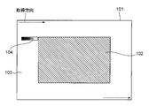
- FIG. 1 is a diagram illustrating a configuration of an output image region of the image sensor in the present embodiment.
- the entire imaging area 101 is image data of the entire screen output by the imaging element, and has a configuration including an effective image area 102, an invalid image area 103, and a diagnostic data area 104.
- the effective image area 102 is an area having image data used in the image recognition processing unit 207 for recognizing a three-dimensional object, and the invalid image area 103 does not use image data in the image recognition processing unit 207. It is an area.
- the diagnostic data area 104 is an area stored in a part of the invalid image area 103.
- the entire imaging area 101 is divided into an effective image area 102 in which output image data is used for image calculation, and an invalid image area 103 in which output image data is not used in image calculation.
- a diagnosis data area 104 having fixing diagnosis data for diagnosing whether or not the data line signal of the image pickup device portion is in a fixing state is provided.
- the diagnostic data area 104 has data for fixing diagnosis that can detect the fixing state of the data line signal.
- the diagnosis data area 104 is HI that is fixed value data that can detect the HI level fixing state of the data line signal. It has level fixation diagnosis data 302 and LO level fixation diagnosis data 301 which is fixed value data capable of detecting the LO level fixation state of the data line signal.
- the diagnostic data area 104 is disposed at a position where image data is acquired in front of the effective image area 102 in the data acquisition direction, and is provided in the upper left corner of the entire imaging area 101 in this embodiment.
- FIG. 3 is a configuration diagram of a diagnostic data area, and is a diagram illustrating a configuration example of fixation diagnostic data when an image sensor having a 16-bit gradation is used.
- the LO level fixation diagnosis data 301 includes diagnosis data for at least 16 pixels in order to execute a fixation diagnosis of a 16-bit gradation data line signal.
- the expected value data embedded in the invalid image area 103 as diagnostic data is set to HI only for the bit corresponding to the diagnosis target data line bit, and the other bits are set to LO. Set a correct value.
- the expected value data for detecting the Bit 0 LO level fixation state is set to 0x0001 (only the value of Bit 0 is HI) as diagnostic 16-bit data.
- the value of the pixel storing the Bit0 LO level fixation diagnosis data is 0x0000 when the image data output from the image sensor is acquired. It can be diagnosed that the data line signal is in the LO level fixed state.
- the LO level fixation diagnosis data for Bit 1 to Bit 15 is set in the same manner.
- the HI level fixation diagnostic data 302 has diagnostic data for 16 pixels which is the same as the gradation of the image sensor.
- the expected value data embedded in the invalid image area 103 as diagnostic data is LO only for the bit corresponding to the diagnosis target data line bit, and the other bits are HI. Set a correct value.
- 0xFFFE (only the value of Bit0 is LO) is set as the expected value data for detecting the HI level fixed state of Bit0 as 16-bit data for diagnosis.
- the value of the pixel storing the bit 0 HI level fixing diagnosis data is 0xFFFF when acquiring the image data output from the image sensor. It can be diagnosed that the data line signal is in the HI level fixed state.
- the HI level fixation diagnosis data for Bit 1 to Bit 15 is set.
- the LO level sticking state or the HI level sticking state of the data line signal can be detected.
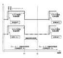
- FIG. 2 is a block diagram of the stereo camera 201 according to an embodiment of the present invention.
- the stereo camera 201 includes a right imaging element unit 202 attached on the right side with respect to the vehicle traveling direction, a left imaging element unit 203 attached on the left side with respect to the vehicle traveling direction, the right imaging element unit 202, and the left imaging element.
- An image data acquisition unit 204 that acquires image data output from the unit 203, and an image calculation processing unit 205 that calculates parallax information and the like necessary for the three-dimensional object recognition process from the left and right image data acquired by the image data acquisition unit 204.
- the image data transfer unit 206 for transferring the left and right image data acquired by the image data acquisition unit 204 and the image data generated by the image calculation processing unit 205 to the processing area, and various image data such as parallax information.
- the data line signal is in a fixed state using the image recognition processing unit 207 that executes solid object recognition and the image data line fixing diagnosis data.
- a failure diagnosis processing unit 208 that performs a failure diagnosis of whether or not, a vehicle control processing unit 209 that calculates a vehicle control process based on the recognition result detected by the image recognition processing unit 207, and a failure diagnosis processing unit 208
- a notification processing unit 210 is provided for transmitting an abnormal state to the outside.
- the stereo camera 201 connects the vehicle control information calculated by the vehicle control processing unit 209 and the failure information output from the notification processing unit 210 to an in-vehicle communication bus 211 such as a CAN (Controller (Area Network).
- the output information of the stereo camera 201 is transmitted to the external ECU.
- the right image sensor unit 202 and the left image sensor unit 203 each have a configuration in which a plurality of pixels are arranged in a matrix.
- Image data of images captured by the right imaging element unit 202 and the left imaging element unit 203 is acquired by the image data acquisition unit 204.
- image data is acquired in the row direction from the pixel at the left end of the first column in the entire image capturing area 101 toward the right end, and sequentially downward from the second column. All image data (image data of the entire screen) of the entire imaging region 101 is acquired while moving in the column direction.
- the image data of the effective image area 102 is used for the image calculation processing of the image calculation processing unit 205 from all the acquired image data. Since the diagnostic data area 104 is provided at the upper left corner of the entire imaging area 101, the diagnostic data area 104 is acquired first when acquiring image data from the entire imaging area 101.
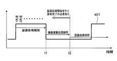
- FIG. 4 is a diagram illustrating an example of the timing from the acquisition of image data from the right image sensor unit 202 and the left image sensor unit 203 to the start of processing in the image recognition processing unit 207.
- the vertical synchronization signal 401 representing the timing of obtaining image data from the image sensor is a HI level signal during the image data output period
- the data of the total number of effective lines output from the image sensor is obtained as an image data acquisition unit.
- the vertical synchronization signal 401 is at the HI level.
- the vertical synchronization signal 401 becomes the LO level, and the image calculation processing unit 205 starts the image calculation processing at the same timing. Then, since the image data necessary for the three-dimensional object recognition is prepared at the time t2 when the arithmetic processing in the image arithmetic processing unit 205 is completed, the arithmetic processing in the image recognition processing unit 207 is started. Therefore, it is necessary to detect the fixed state of the data line signal from the image sensor before the arithmetic processing in the image recognition processing unit 207 is started.
- the fixation diagnosis data in the diagnosis data area 104 is also stored.
- the fixation state of the data line signal before the recognition process is started that is, at least one of the image acquisition period and the image calculation processing period. Therefore, it is possible to quickly and accurately detect that the data line signal from the image sensor is in a fixed state and the three-dimensional object recognition is not normally performed without being affected by the environment such as light and dark, and more reliable.
- a highly efficient driving support system can be provided.
- the data line sticking diagnosis data area of the present invention may be stored in the area shown in FIG. 5 as an example.
- FIG. 5 is a diagram illustrating an example of the storage destination of the data line sticking diagnosis data area.
- the diagnostic data area 104 is arranged at a position immediately before the image data of the effective image area 102 is acquired.
- the diagnostic data area 104 is continuously arranged on the front side in the data acquisition direction from the start point at which the acquisition of the image data in the effective image area 102 is started.
- the image data is acquired from the left end to the right end of the entire imaging area 101, and sequentially moves downward to acquire all the image data of the entire imaging area 101.
- the data area 104 is continuously arranged at a position on the left side of the start point that is the upper left end of the effective image area 102 in the drawing. By disposing the diagnostic data area 104 at such a position, it is possible to diagnose the fixed state of the data line signal immediately before the image data of the effective image area 102 is acquired from the image sensor.
- the data line sticking diagnosis data area of the present invention may be stored in the area shown in FIG. 6 as an example.
- FIG. 6 is a diagram illustrating an example of the storage destination of the data line sticking diagnosis data area.
- the diagnostic data area 104 is arranged behind the effective image area 102 in the data acquisition direction, particularly immediately after all the image data in the effective image area 102 is acquired. It is arranged at the position.
- the diagnostic data area 104 is continuously arranged on the rear side in the data acquisition direction from the end point where the acquisition of the image data in the effective image area 102 ends.
- the image data is acquired from the left end to the right end of the entire imaging area 101, and sequentially moves downward to acquire all the image data of the entire imaging area 101.
- the data area 104 is continuously arranged at a position on the right side of the end point at the lower right end of the effective image area 102 in the drawing.
- FIG. 7 is a diagram illustrating an example of timing for executing a diagnostic process on the left and right imaging element units. It is conceivable that the calculation processing load in the image recognition processing unit 207 varies depending on the image data output from the image sensor. As an example, when image data including a plurality of three-dimensional objects such as a preceding vehicle or a pedestrian is acquired while the vehicle is traveling, a large number of three-dimensional object detection processes operate, which increases the processing load. On the other hand, when the vehicle is stopped and there is no three-dimensional object and image data with no target to be recognized is acquired, the processing load of the image recognition processing unit 207 is reduced.
- the image recognition process may not be completed within a predetermined time due to the influence of the processing load generated by the fault diagnosis execution.
- the number of image sensor units that execute the fixation diagnosis of the data line signal is limited to minimize the influence on the recognition processing execution. It becomes possible to limit to the limit.
- any of the image data output from the left and right imaging element units 202 and 203 has a high priority
- the imaging that outputs the image data having a high priority is performed. It is desirable to preferentially execute the data line signal fixation diagnosis for the element portion.
- priority is given to data line signal fixation diagnosis of the image sensor unit. Should be done.
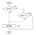
- FIG. 8 is a flowchart for explaining processing content switching according to priority and processing load.
- the priority of the image sensor unit is confirmed (S801).
- the priority is set between the pair of left and right imaging element units.
- the diagnostic process on the image sensor unit on the higher priority side is executed regardless of the processing load. To do.
- the processing load status of the frame is confirmed (S802), and it is determined whether or not diagnostic processing is performed.
- the diagnostic processing of the right imaging element unit 202 on the higher priority side is performed based on the determination that the processing load in the recognition processing period of frame 1 is greater than or equal to a reference value (processing load: large). And the diagnostic processing of the left image sensor unit 203 on the lower priority side is not executed. Then, based on the determination that the processing load in the recognition processing period of frame 2 is smaller than the reference value (processing load: small), the diagnostic processing of the right imaging element unit 202 on the higher priority side and the priority are Both of the diagnostic processes of the left image sensor unit 203 on the lower side are executed.
Landscapes
- Engineering & Computer Science (AREA)
- Multimedia (AREA)
- Signal Processing (AREA)
- Physics & Mathematics (AREA)
- General Physics & Mathematics (AREA)
- Health & Medical Sciences (AREA)
- Biomedical Technology (AREA)
- General Health & Medical Sciences (AREA)
- Studio Devices (AREA)
- Traffic Control Systems (AREA)
- Transforming Light Signals Into Electric Signals (AREA)
- Testing, Inspecting, Measuring Of Stereoscopic Televisions And Televisions (AREA)
Abstract
Description
全撮像領域101は、撮像素子によって出力される全画面の画像データであり、有効画像領域102と無効画像領域103と診断用データ領域104とを有した構成となっている。有効画像領域102は、例えば立体物を認識するための画像認識処理部207において使用される画像データを有する領域であり、無効画像領域103は、画像認識処理部207では画像データが使用されていない領域である。そして、診断用データ領域104は、無効画像領域103内の一部に格納されている領域である。すなわち、全撮像領域101は、出力される画像データが画像演算に用いられる有効画像領域102と、出力される画像データが画像演算に用いられない無効画像領域103とに区分され、無効画像領域103内に撮像素子部のデータ線信号が固着状態となっているか否かを診断するための固着診断用データを有する診断用データ領域104が設けられている。
LOレベル固着診断用データ301は、16ビット階調のデータ線信号の固着診断を実行するために最低16画素分の診断用データを有する。データ線信号のLOレベル固着状態を検出するために、診断用データとして無効画像領域103に埋め込む期待値データは、診断対象データ線ビットに相当するビットのみHI、上記以外のビットはLOとなるような値を設定する。
ステレオカメラ201は、車両進行方向に対して右側に取り付けられた右撮像素子部202と、車両進行方向に対して左側に取り付けられた左撮像素子部203と、右撮像素子部202および左撮像素子部203から出力される画像データを取得する画像データ取得部204と、画像データ取得部204で取得された左右画像データから立体物の認識処理で必要な視差情報などを算出する画像演算処理部205と、画像データ取得部204で取得された左右画像データや画像演算処理部205で生成された画像データを使用する処理領域に転送する画像データ転送部206と、視差情報など各種画像データを元にして立体物認識などを実行する画像認識処理部207と、画像データ線固着診断用データを用いてデータ線信号が固着状態であるか否かの故障診断を実行する故障診断処理部208と、画像認識処理部207にて検出された認識結果を元にして車両制御処理を演算する車両制御処理部209と、故障診断処理部208にて異常判定された際に、外部に異常状態を伝達するための報知処理部210を備えている。
撮像素子からの画像データ取得タイミングを表す垂直同期信号401が、画像データ出力期間中はHIレベル信号になっている例を挙げると、撮像素子が出力する全有効ライン数のデータを画像データ取得部204で取得中のとき、すなわち、全撮像領域101の画像データを取得中のときは、垂直同期信号401はHIレベルとなっている。
撮像素子から出力される画像データによって、画像認識処理部207での演算処理負荷が変動することが考えられる。例として、車両走行中に先行車両や歩行者など立体物のターゲットが複数存在する画像データを取得した場合、立体物検知処理が数多く動作するため、処理負荷が大きくなる。一方で、車両停止中で立体物が何もなく、認識すべきターゲットが存在しない画像データを取得した場合は、画像認識処理部207の処理負荷は軽くなる。
初めに、撮像素子部の優先度の確認(S801)を実行する。左右一対の撮像素子部は、互いの間で優先度が設定されている。一対の撮像素子部のうち、診断対象の撮像素子部が優先度の高い側の場合(S801でYES)、処理負荷の大小に関わらず、優先度が高い側の撮像素子部の診断処理を実行する。そして、優先度が低い側の撮像素子部の場合、当該フレームの処理負荷状況の確認(S802)を実行し、診断処理の実行有無を判断する。
102 有効画像領域
103 無効画像領域
104 診断用データ領域
201 ステレオカメラ(車載用カメラ装置)
202 右撮像素子部
203 左撮像素子部
204 画像データ取得部
205 画像演算処理部
206 画像データ転送部
207 画像認識処理部
208 故障診断処理部
209 車両制御処理部
210 報知処理部
211 車載用通信バス
301 LOレベル固着診断用データ
302 HIレベル固着診断用データ
401 垂直同期信号
Claims (7)
- 撮像素子部のデータ線信号が固着状態となっているか否かを診断する故障診断処理部を有する車載用カメラ装置であって、
前記撮像素子部は、出力される画像データが画像演算に用いられる有効画像領域と、出力される画像データが画像演算に用いられない無効画像領域とに区分される全撮像領域を有し、前記無効画像領域内に前記撮像素子部のデータ線信号が固着状態となっているか否かを診断するための固着診断用データを有する診断用データ領域が設けられており、
前記故障診断処理部は、前記全撮像領域の画像データを取得している画像取得期間と、該画像取得期間の後で前記有効画像領域の画像データに基づいて画像演算処理を行っている画像演算処理期間との少なくとも一方において、前記診断用データ領域の固着診断用データを用いて故障診断処理を行うことを特徴とする車載用カメラ装置。 - 請求項1に記載の車載用カメラ装置であって、
前記診断用データ領域は、前記有効画像領域よりもデータ取得方向前側に配置されている車載用カメラ装置。 - 請求項2に記載の車載用カメラ装置であって、
前記診断用データ領域は、前記有効画像領域における前記画像データの取得を開始する開始点よりもデータ取得方向前側に連続して配置されている車載用カメラ装置。 - 請求項1に記載の車載用カメラ装置であって、
前記診断用データ領域は、前記有効画像領域よりもデータ取得方向後側に配置されている車載用カメラ装置。 - 請求項4に記載の車載用カメラ装置であって、
前記診断用データ領域は、前記有効画像領域における前記画像データの取得を終了する終了点よりもデータ取得方向後側に連続して配置されている車載用カメラ装置。 - 請求項1に記載の車載用カメラ装置であって、
前記有効画像領域の画像データに基づいて画像認識処理を行う画像認識処理部を有し、
前記故障診断処理部は、前記画像認識処理部による画像認識処理の処理負荷状況に応じて前記撮像素子部の診断処理の実行有無を判断する車載用カメラ装置。 - 請求項6に記載の車載用カメラ装置であって、
互いの間で優先度が設定された左右一対の前記撮像素子部を有し、
前記故障診断処理部は、前記画像認識処理部による画像認識処理の処理負荷が予め設定された基準値以上の場合に、前記撮像素子部のうち、優先度が高い側の診断処理のみを実行し、前記基準値よりも小さい場合に、優先度が高い側と低い側の両方の診断処理を実行する車載用カメラ装置。
Priority Applications (3)
| Application Number | Priority Date | Filing Date | Title |
|---|---|---|---|
| EP16740008.4A EP3249902A4 (en) | 2015-01-20 | 2016-01-12 | On-vehicle camera device |
| US15/538,865 US10152890B2 (en) | 2015-01-20 | 2016-01-12 | On-vehicle camera device |
| JP2016570579A JP6259132B2 (ja) | 2015-01-20 | 2016-01-12 | 車載用カメラ装置 |
Applications Claiming Priority (2)
| Application Number | Priority Date | Filing Date | Title |
|---|---|---|---|
| JP2015008837 | 2015-01-20 | ||
| JP2015-008837 | 2015-01-20 |
Publications (1)
| Publication Number | Publication Date |
|---|---|
| WO2016117401A1 true WO2016117401A1 (ja) | 2016-07-28 |
Family
ID=56416948
Family Applications (1)
| Application Number | Title | Priority Date | Filing Date |
|---|---|---|---|
| PCT/JP2016/050603 Ceased WO2016117401A1 (ja) | 2015-01-20 | 2016-01-12 | 車載用カメラ装置 |
Country Status (4)
| Country | Link |
|---|---|
| US (1) | US10152890B2 (ja) |
| EP (1) | EP3249902A4 (ja) |
| JP (1) | JP6259132B2 (ja) |
| WO (1) | WO2016117401A1 (ja) |
Cited By (5)
| Publication number | Priority date | Publication date | Assignee | Title |
|---|---|---|---|---|
| JP2018061234A (ja) * | 2016-09-30 | 2018-04-12 | キヤノン株式会社 | 撮像装置、撮像システム、移動体、および、制御方法 |
| EP3454555A1 (en) * | 2017-09-11 | 2019-03-13 | Kabushiki Kaisha Toshiba | Image processing apparatus and failure diagnosis control method |
| JP2019057109A (ja) * | 2017-09-21 | 2019-04-11 | 株式会社東芝 | 演算処理装置およびその方法 |
| US10477201B2 (en) | 2017-07-25 | 2019-11-12 | Canon Kabushiki Kaisha | Image capturing device, image capturing system, and moving body |
| CN110602482A (zh) * | 2019-08-07 | 2019-12-20 | 武汉兴图新科电子股份有限公司 | 一种视频系统的故障自诊断装置及方法 |
Families Citing this family (6)
| Publication number | Priority date | Publication date | Assignee | Title |
|---|---|---|---|---|
| KR101832189B1 (ko) * | 2015-07-29 | 2018-02-26 | 야마하하쓰도키 가부시키가이샤 | 이상화상 검출장치, 이상화상 검출장치를 구비한 화상 처리 시스템 및 화상 처리 시스템을 탑재한 차량 |
| KR102462502B1 (ko) * | 2016-08-16 | 2022-11-02 | 삼성전자주식회사 | 스테레오 카메라 기반의 자율 주행 방법 및 그 장치 |
| DE102017219869A1 (de) * | 2017-11-08 | 2019-05-09 | Continental Teves Ag & Co. Ohg | Steuergerät für ein Kraftfahrzeug und Verfahren zum Betreiben des Steuergeräts |
| JP7098346B2 (ja) * | 2018-02-13 | 2022-07-11 | ソニーセミコンダクタソリューションズ株式会社 | 撮像装置および撮像システム |
| JP7187564B2 (ja) * | 2018-08-21 | 2022-12-12 | 日立Astemo株式会社 | 画像処理装置 |
| JP7218216B2 (ja) * | 2019-03-08 | 2023-02-06 | 株式会社東芝 | 画像処理装置、及び、検出方法 |
Citations (2)
| Publication number | Priority date | Publication date | Assignee | Title |
|---|---|---|---|---|
| JP2009033550A (ja) * | 2007-07-27 | 2009-02-12 | Nikon Corp | 撮像装置 |
| JP2009118427A (ja) * | 2007-11-09 | 2009-05-28 | Panasonic Corp | 固体撮像装置およびその駆動方法 |
Family Cites Families (19)
| Publication number | Priority date | Publication date | Assignee | Title |
|---|---|---|---|---|
| JP3907254B2 (ja) * | 1996-12-27 | 2007-04-18 | キヤノン株式会社 | 画像記録装置、画像記録方法及びコンピュータ可読の記録媒体 |
| US6118482A (en) | 1997-12-08 | 2000-09-12 | Intel Corporation | Method and apparatus for electrical test of CMOS pixel sensor arrays |
| US6791619B1 (en) * | 1998-09-01 | 2004-09-14 | Fuji Photo Film Co., Ltd. | System and method for recording management data for management of solid-state electronic image sensing device, and system and method for sensing management data |
| JP4346968B2 (ja) * | 2003-06-13 | 2009-10-21 | キヤノン株式会社 | 放射線撮影方法、放射線撮影装置、及びコンピュータプログラム |
| DE102004020331B3 (de) | 2004-04-26 | 2005-10-20 | Pilz Gmbh & Co Kg | Vorrichtung und Verfahren zum Aufnehmen eines Bildes |
| US9848172B2 (en) * | 2006-12-04 | 2017-12-19 | Isolynx, Llc | Autonomous systems and methods for still and moving picture production |
| JP5278819B2 (ja) * | 2009-05-11 | 2013-09-04 | 株式会社リコー | ステレオカメラ装置及びそれを用いた車外監視装置 |
| JP5400718B2 (ja) * | 2010-07-12 | 2014-01-29 | 株式会社日立国際電気 | 監視システムおよび監視方法 |
| JP6137921B2 (ja) * | 2013-04-16 | 2017-05-31 | オリンパス株式会社 | 画像処理装置、画像処理方法及びプログラム |
| US9742974B2 (en) * | 2013-08-10 | 2017-08-22 | Hai Yu | Local positioning and motion estimation based camera viewing system and methods |
| JP6249769B2 (ja) * | 2013-12-27 | 2017-12-20 | オリンパス株式会社 | 内視鏡装置、内視鏡装置の作動方法及びプログラム |
| JP6500355B2 (ja) * | 2014-06-20 | 2019-04-17 | 富士通株式会社 | 表示装置、表示プログラム、および表示方法 |
| JP6137081B2 (ja) * | 2014-07-29 | 2017-05-31 | 株式会社デンソー | 車載機器 |
| JP6448340B2 (ja) * | 2014-12-10 | 2019-01-09 | キヤノン株式会社 | 固体撮像装置、撮像システム及び固体撮像装置の駆動方法 |
| CN107113383B (zh) * | 2015-01-20 | 2020-03-17 | 奥林巴斯株式会社 | 图像处理装置、图像处理方法和存储介质 |
| CN106161922B (zh) * | 2015-04-22 | 2019-05-14 | 北京智谷睿拓技术服务有限公司 | 图像采集控制方法和装置 |
| CN107534730B (zh) * | 2015-04-28 | 2020-06-23 | 索尼公司 | 图像处理装置及图像处理方法 |
| JP6546457B2 (ja) * | 2015-06-19 | 2019-07-17 | ブリルニクス インク | 固体撮像装置およびその駆動方法、電子機器 |
| JP6701033B2 (ja) * | 2016-08-30 | 2020-05-27 | キヤノン株式会社 | 電子機器およびその制御方法 |
-
2016
- 2016-01-12 WO PCT/JP2016/050603 patent/WO2016117401A1/ja not_active Ceased
- 2016-01-12 EP EP16740008.4A patent/EP3249902A4/en not_active Withdrawn
- 2016-01-12 JP JP2016570579A patent/JP6259132B2/ja active Active
- 2016-01-12 US US15/538,865 patent/US10152890B2/en active Active
Patent Citations (2)
| Publication number | Priority date | Publication date | Assignee | Title |
|---|---|---|---|---|
| JP2009033550A (ja) * | 2007-07-27 | 2009-02-12 | Nikon Corp | 撮像装置 |
| JP2009118427A (ja) * | 2007-11-09 | 2009-05-28 | Panasonic Corp | 固体撮像装置およびその駆動方法 |
Non-Patent Citations (1)
| Title |
|---|
| See also references of EP3249902A4 * |
Cited By (9)
| Publication number | Priority date | Publication date | Assignee | Title |
|---|---|---|---|---|
| JP2018061234A (ja) * | 2016-09-30 | 2018-04-12 | キヤノン株式会社 | 撮像装置、撮像システム、移動体、および、制御方法 |
| US10477201B2 (en) | 2017-07-25 | 2019-11-12 | Canon Kabushiki Kaisha | Image capturing device, image capturing system, and moving body |
| EP3454555A1 (en) * | 2017-09-11 | 2019-03-13 | Kabushiki Kaisha Toshiba | Image processing apparatus and failure diagnosis control method |
| CN109495663A (zh) * | 2017-09-11 | 2019-03-19 | 株式会社东芝 | 图像处理装置以及故障诊断控制方法 |
| JP2019049884A (ja) * | 2017-09-11 | 2019-03-28 | 株式会社東芝 | 画像処理装置、および故障診断制御方法 |
| US10694176B2 (en) | 2017-09-11 | 2020-06-23 | Kabushiki Kaisha Toshiba | Image processing apparatus and failure diagnosis control method |
| US10911746B2 (en) | 2017-09-11 | 2021-02-02 | Kabushiki Kaisha Toshiba | Image processing apparatus and failure diagnosis control method |
| JP2019057109A (ja) * | 2017-09-21 | 2019-04-11 | 株式会社東芝 | 演算処理装置およびその方法 |
| CN110602482A (zh) * | 2019-08-07 | 2019-12-20 | 武汉兴图新科电子股份有限公司 | 一种视频系统的故障自诊断装置及方法 |
Also Published As
| Publication number | Publication date |
|---|---|
| JP6259132B2 (ja) | 2018-01-10 |
| US10152890B2 (en) | 2018-12-11 |
| JPWO2016117401A1 (ja) | 2017-08-10 |
| US20170345306A1 (en) | 2017-11-30 |
| EP3249902A1 (en) | 2017-11-29 |
| EP3249902A4 (en) | 2018-08-22 |
Similar Documents
| Publication | Publication Date | Title |
|---|---|---|
| JP6259132B2 (ja) | 車載用カメラ装置 | |
| EP3094075B1 (en) | In-vehicle-camera image processing device | |
| US10239446B2 (en) | Vehicle sensing system using daisy chain of sensors | |
| US20160162743A1 (en) | Vehicle vision system with situational fusion of sensor data | |
| JP6221464B2 (ja) | ステレオカメラ装置、移動体制御システム及び移動体、並びにプログラム | |
| US10723347B2 (en) | Vehicle control device and vehicle control method | |
| US20160217335A1 (en) | Stixel estimation and road scene segmentation using deep learning | |
| JP6458579B2 (ja) | 画像処理装置 | |
| EP3168750B1 (en) | Information processing system | |
| US9852502B2 (en) | Image processing apparatus | |
| JP2001211466A (ja) | 自己診断機能を有する画像処理システム | |
| JP2014187496A (ja) | 故障検出装置 | |
| US10853692B2 (en) | Vicinity supervising device and method for supervising vicinity of vehicle | |
| KR102837493B1 (ko) | 화상 처리 장치, 이동 장치 및 방법, 그리고 프로그램 | |
| KR20130053605A (ko) | 차량의 주변영상 표시 장치 및 그 방법 | |
| JP2007293672A (ja) | 車両用撮影装置、車両用撮影装置の汚れ検出方法 | |
| CN111345038A (zh) | 摄像机系统的测试方法,摄像机系统的控制设备,摄像机系统和具有该摄像机系统的车辆 | |
| JP4539427B2 (ja) | 画像処理装置 | |
| JP2006300890A (ja) | 画像処理検査装置及び画像処理検査方法 | |
| JP4797441B2 (ja) | 車両用画像処理装置 | |
| JP2008042759A (ja) | 画像処理装置 | |
| CN112334944B (zh) | 摄像机装置的标志识别方法及标志识别装置 | |
| JP2025129851A (ja) | 運転者視野欠損推定装置 | |
| JP2018139120A (ja) | 情報処理システム | |
| EP3518523B1 (en) | Image processing device |
Legal Events
| Date | Code | Title | Description |
|---|---|---|---|
| 121 | Ep: the epo has been informed by wipo that ep was designated in this application |
Ref document number: 16740008 Country of ref document: EP Kind code of ref document: A1 |
|
| ENP | Entry into the national phase |
Ref document number: 2016570579 Country of ref document: JP Kind code of ref document: A |
|
| REEP | Request for entry into the european phase |
Ref document number: 2016740008 Country of ref document: EP |
|
| WWE | Wipo information: entry into national phase |
Ref document number: 15538865 Country of ref document: US |
|
| NENP | Non-entry into the national phase |
Ref country code: DE |