WO2016117635A1 - Dispositif de transport - Google Patents
Dispositif de transport Download PDFInfo
- Publication number
- WO2016117635A1 WO2016117635A1 PCT/JP2016/051674 JP2016051674W WO2016117635A1 WO 2016117635 A1 WO2016117635 A1 WO 2016117635A1 JP 2016051674 W JP2016051674 W JP 2016051674W WO 2016117635 A1 WO2016117635 A1 WO 2016117635A1
- Authority
- WO
- WIPO (PCT)
- Prior art keywords
- tab
- transfer
- cutting
- clip
- tab material
- Prior art date
- Legal status (The legal status is an assumption and is not a legal conclusion. Google has not performed a legal analysis and makes no representation as to the accuracy of the status listed.)
- Ceased
Links
Images










Classifications
-
- B—PERFORMING OPERATIONS; TRANSPORTING
- B65—CONVEYING; PACKING; STORING; HANDLING THIN OR FILAMENTARY MATERIAL
- B65B—MACHINES, APPARATUS OR DEVICES FOR, OR METHODS OF, PACKAGING ARTICLES OR MATERIALS; UNPACKING
- B65B7/00—Closing containers or receptacles after filling
- B65B7/16—Closing semi-rigid or rigid containers or receptacles not deformed by, or not taking-up shape of, contents, e.g. boxes or cartons
- B65B7/28—Closing semi-rigid or rigid containers or receptacles not deformed by, or not taking-up shape of, contents, e.g. boxes or cartons by applying separate preformed closures, e.g. lids, covers
Definitions
- the present invention relates to a transport device, and in particular, to a top plate of a liquid paper container used as a container for soft drinks, such as cart cans (trademark of Toppan Printing Co., Ltd.), brick pack (trademark of Meiji Dairies), etc.
- the present invention relates to a technique suitable for use in attaching a tab tape to be attached to a formed opening.
- a liquid paper container is a paper container having a cylindrical body member (side material) and a circular outer peripheral edge standing on the outer surface side (upper) lid material (top material) ) And a bottom material (bottom material) having a circular outer peripheral edge standing on the outer surface side (lower part).
- the present invention has been made in view of the above circumstances, and intends to achieve the object of providing a transport device capable of achieving both the ease of opening a tab material and the ease of pasting. It is.
- a transport apparatus including a liquid paper container having a cylindrical body member and a cover material with an outer peripheral edge standing upward, such that the cover material is positioned on an upper surface of the liquid paper container.
- Cutting that forms a tab material having a first end and a second end by cutting the tab sheet material supplied from the supply device, a feeding device that feeds the tab sheet material, and a moving device that moves in a standing position While holding the second end of the device and the tab material, the tab material can be rotated around a substantially horizontal axis from a cutting position located above the lid material to a pasting position on the upper surface of the lid material.
- a temporary attachment device for temporarily attaching the first end of the tab member rotated to the attaching position to the lid member.
- the structure which concerns on the said aspect it is located in the center of a cover material, without being influenced by the outer-periphery edge part of the standing cover material by hold
- the tab material can be conveyed to the opening, and the tab material is not caught in the cutting device.
- the cutting device may include an embossing portion that embosses the first end of the tab material.
- the transfer device includes a tabular tab transfer that is rotatable around the axis, and is rotatable integrally with the tab transfer, and the second tab material between the tab transfer and the upper surface of the tab transfer. There may be provided a tab clip that sandwiches and holds the end.
- the transfer device includes an urging member that urges the tab clip toward the tab transfer in a direction of sandwiching the second end of the tab member, and the urging member at the cutting position of the tab clip.
- An urging switching portion that urges the tab clip by the urging member when releasing the urging and urging the tab transfer from the cutting position to the pasting position may be provided. .
- the urging of the tab clip is released to set the second end of the tab material to a predetermined position, and the rotation of the tab transfer is performed.
- the tab clip is urged toward the tab transfer, and even if the tab material is caught on the tip of the cutting device, the tab material is pulled out from the cutting device and is transported to the attaching position without any trouble.
- the urging of the tab clip can be controlled in conjunction with the rotational movement of the tab transfer.
- the transfer device may be provided with a suction portion that adsorbs the tab material on the upper surface of the tab transfer.
- the tab material in addition to the urging force that urges the tab clip toward the tab transfer in the direction of sandwiching the second end of the tab material, the tab material can be sucked and the tab transfer can be rotated. In the moving operation, it is possible to prevent the tab member from being pulled with respect to the tab transfer by being pulled by the cutting device.
- the suction portion may be provided at a position farther from the cutting device than the position at which the tab clip and the tab transfer sandwich the tab material, and be capable of adsorbing the second end of the tab material.
- the tab material can be held in the tab transfer without affecting the operation of the tab clip.
- the transfer device has a guide portion that moves the second end of the tab material supplied from the cutting device along the upper surface of the tab transfer to a position facing the upper surface of the tab transfer at the cutting position. It may be provided.
- a plurality of sets of the cutting device, the transfer device, and the tacking device may be provided, and the tab material may be simultaneously supplied to each of a plurality of liquid paper containers.
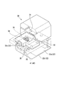
- FIG. 1 is a front view showing a transfer device (transfer means) of a transport device in the present embodiment.
- FIG. 2 is a partially transparent perspective view showing the transfer device of the transport device in the present embodiment.
- FIG. 3 is an exploded perspective view showing the transfer device of the transport device in the present embodiment.
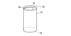
- FIG. 15 is a diagram illustrating a liquid paper container to be processed by the transport device according to the present embodiment.
- reference numeral 1 denotes a transport device
- reference numeral C denotes a liquid paper container.
- the transport device 1 according to the present embodiment is a device that sticks the tab material B to the liquid paper container C.
- the transport device 1 according to this embodiment includes a material roll 11 in which a continuous tape-like tab material (tab sheet material) S ⁇ b> 1 is wound as a supply device (supply means) 10, and the material roll 11.
- a cutting device (cutting means) 20 for receiving and cutting the tab material S1 unwound from the tab material S into a contour shape of the tab material S, and a conveyor (moving device, moving) for transporting the liquid paper container C below the cutting device 20 Means) 60 and the upper surface of the liquid paper container C which is received on the conveyor 60 while receiving the tab material S after molding from the cutting device 20 and adjusting the tab material S to the conveyance speed of the conveyor 60.
- a transfer device (transfer means) 30 for supplying to the vicinity of the opening C6 provided in the lid material C3 and a temporary attachment device (temporary attachment means) 50 for temporarily attaching the tab material S to the lid material C2.
- a cylindrical liquid paper container (paper container) C as an example in the present embodiment is a resin layer obtained by melt-extrusion of at least a paper layer and a sealant layer having a barrier film layer.
- 1 is a paper container C formed by molding a laminated material mainly composed of paper base materials laminated via a sheet.
- the paper container C includes a cylindrical body member (side material) C1, a circular outer peripheral edge C2 standing on the outer surface (of the paper container C) (upper part) (top material) C3, and a lid material C3.
- a circular outer peripheral edge portion is provided with a (lower) bottom material (bottom material) C4 standing on the outer surface.
- the inner surface of the outer peripheral edge portion C2 of the lid member C3 is joined to the upper inner surface of the body member C1, and the inner surface of the outer peripheral edge portion of the bottom member C4 is joined to the lower inner surface of the body member C1.
- It has a simple cylindrical structure (bottomed cylindrical shape).
- the liquid paper container C is provided with an opening C6 in the lid member C3, and the opening C6 is sealed with a tab material S attached thereto.
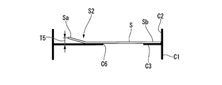
- the tab material S is covered with a lid material for easy opening at the first end (one end) Sa of the tab material S, which is not overlapped with the opening C6.
- An embossed portion S2 formed in a convex shape toward the C3 surface is provided. The shape of the embossed portion S2 can be set as appropriate.
- the tab material S has a first end Sa that has a contour shape with a center protruding in the width direction to ensure ease of opening, and a second end (other end) Sb that is a lid material.
- the contour shape is set so as to substantially contact the outer peripheral edge C2 of C3.
- the conveying device supplies a continuous tape-shaped tab material S1 and cuts the tape-shaped tab material S1 so as to have a predetermined profile with a predetermined length, and a position where the opening C6 is attached. Transport to.
- the supply device 10 includes rollers 12a, 12b and the like that supply the cutting device 20 at a predetermined speed as a material roll 11 wound with a continuous tape-like tab material S1. As long as the material roll 11 can supply the tab material S1 to the cutting device 20, the installation position of the material roll 11 is not limited.
- the cutting device 20 separates the continuously supplied tab material S1 at a first end (first end side, a position close to the first end), and cuts the tab material (one tab). S is formed. Further, the cutting device 20 has an upper blade (punch) 21 and a lower blade (die) 22 that cut the supplied tape-shaped tab material S1 from both sides in the thickness direction, and more than the upper blade 21 and the lower blade 22.
- a driving device (not shown) which is a cylinder or the like (drive means), the.
- the cutting device 20 is arranged so that the tape-like tab material S1 is arranged so that the width direction of the tab material S1 is substantially horizontal, and the tip of the cutting device 20 is lowered. It can move along the surface of the lower base 26.
- the lower base 26 is provided with an upper base 25 that is disposed so as to be opposed to each other, and can be moved so that the upper base 25 comes close to the lower base 26 by a driving device (not shown). Further, the upper base 25 is movable by the urging member 27 so as to be separated from the lower base 26.
- the upper blade 21 integrally formed with the upper base 25 comes into contact with the lower blade 22 at the corresponding position to form a tape-like tab.
- the material S1 can be cut.
- the convex portion 23 formed integrally with the upper base portion 25 can be embossed on the tab material S close to the concave portion 24 at the corresponding position.
- the upper blade 21 and the convex portion 23 can reciprocate in the normal direction (vertical direction) of the surface 26a with respect to the surface 26a of the lower base portion 26 formed in a substantially flat surface together with the integrally formed upper base portion 25.
- the convex portion 23 and the concave portion 24 have a shape conforming to the concave-convex shape formed on the tab material S by embossing, and are not particularly limited.
- the convex part 23 and the recessed part 24 are the embossed part S2 provided in two places in the vicinity formed in the protrusion outline shape provided in 1st end Sa of the tab material S, as shown to FIG. 15B. It has the arrangement corresponding to.
- the shapes of the upper blade 21 and the lower blade 22 are set so as to correspond to the contour shape of the tab material S.
- the planar shapes of the upper blade 21 and the lower blade 22 are set so as to correspond.
- a mechanism for removing a cut piece (extracted piece) generated when the tape-like tab material S1 is cut is provided in the hole portion that becomes the lower blade 22 into which the upper blade 21 is fitted at the time of cutting.
- the transfer device 30 is configured to effectively bridge between the cutting device 20 and the conveyor (moving device) 60, and the second end Sb of the cut tab material S is cut.
- the axis line that is substantially horizontal (substantially parallel to the moving direction of the liquid paper container C) from the cutting position of the tab material positioned above the lid material C3 to the attaching position on the upper surface of the lid material C3.
- the tab material S can be rotated.
- the transfer device 30 includes a tabular tab transfer 32 that can rotate around the rotation axis 31 with a substantially horizontal rotation axis 31 as a rotation axis, and a tab transfer 32 that rotates integrally with the tab transfer 32. And a tab clip 33 that is movable and holds the second end Sb of the tab material S with the upper surface 32 a of the tab transfer 32.
- the tab transfer 32 is rotated between a cutting position at the upper position and a bonding position at the lower position around the rotation shaft 31 by a rotation driving device (rotation driving means) (not shown). It is configured to be swingable.
- the rotating shaft 31 extends in a substantially horizontal direction, and is disposed at a position that is substantially flush (on the same plane) as the surface 26 a of the lower base portion 26.
- the upper surface 32a of the tab transfer 32 is the surface 26a of the lower base portion 26.
- the rotational position can be set so as to be substantially flush with each other (on the same plane).
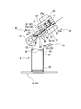
- the cutting position of the tab transfer 32 is such that the upper surface 32a of the tab transfer 32 is substantially flush with the surface 26a of the lower base 26 (on the same plane) as shown in FIGS. Is configured to be movable with the second end Sb side as a tip, and the upper blade 21 and the convex portion 23 are lowered together with the integrally formed upper base portion 25 so as to be capable of cutting the tab material S1. .
- the attachment position of the tab transfer 32 is held in contact with the lid C ⁇ b> 3 of the liquid paper container C with the tip 32 b of the tab transfer 32 standing on the conveyor 60.
- the first end Sa of the tab material S is a position where it can be placed on the lid material C3 of the liquid paper container C.
- the tab clip 33 is attached to the upper surface 32a of the tab transfer 32 so as to be rotatable via a rotating shaft 33a arranged in parallel with the rotating shaft 31, and is also urged by a biasing member.
- the tab clip 33 is urged around the rotation shaft 33 a by the direction 34 toward the tab transfer 32 (opposite direction).
- a convex portion 33b that can press the second end Sb side of the tab material S against the upper surface 32a of the tab transfer 32 is provided at a position facing the upper surface 32a of the tab transfer 32. As shown in FIGS. 6 and 7, the convex portion 33 b can come into contact with the upper surface 32 a of the tab transfer 32 by the biasing of the biasing member 34.
- the tab clip 33 only needs to have the width dimension of the tab clip 33 set to be substantially equal to or slightly larger than the width dimension of the tab material S in the vicinity of the convex portion 33b on the distal end side. It can be set in a timely manner corresponding to the second end Sb side contour shape.
- the tab transfer 32 is provided with a plurality of suction holes 35 opened on the upper surface 32a of the tab transfer 32 as suction portions (suction means). Further, the plurality of suction holes 35 are connected to a decompression pump or the like (not shown), and are configured to be able to suck the second end Sb of the tab material S when the second end Sb of the tab material S is disposed. ing.
- the suction unit can control to switch on and off the suction state.
- the plurality of suction holes 35 as suction portions are convex portions provided on the tip side of the tab clip 33 where the tab clip 33 and the tab transfer 32 sandwich the tab material S. It is provided at a position closer to the rotating shaft 31 than 33b. That is, the suction hole 35 is provided at a position away from the cutting device 20.
- the suction hole 35 is also arranged at a position facing the convex portion 33 b provided on the tip end side of the tab clip 33.
- the arrangement of the suction holes can be set corresponding to the contour shape of the tab material S on the second end Sb side.
- a large number of suction holes 35 can be provided on the entire upper surface 32 a of the tab transfer 32 in a range where the tab material S contacts the upper surface 32 a of the tab transfer 32.
- the unnecessary suction hole 35 can be configured to be switchable so as to cut the connection with the decompression pump so as to correspond to the contour shape of the tab material S to be processed on the second end Sb side.
- the second end Sb side of the tab material S1 supplied from the cutting device 20 is placed at the upper facing position of the tab transfer 32 as shown in FIG.
- a guide unit 40 is provided for movement along the upper surface 32a. The guide portion 40 is fixed so as to be integrated with the cutting device 20 without rotating integrally with the tab transfer 32.
- the guide portion 40 has a guide surface 41 that faces the upper surface 32 a of the tab transfer 32.
- the guide surface 41 is disposed to face the upper surface 32a of the tab transfer 32 so that the distance from the upper surface 32a of the tab transfer 32 decreases from a position close to the cutting device 20 toward a position close to the rotation shaft 31.
- the guide surface 41 is provided from a position close to the cutting device 20 to the vicinity of the suction hole 35 provided on the upper surface 32 a of the tab transfer 32.
- a clip pusher (lever pusher) having a shape protruding downward so as to abut on the upper surface of the tab clip 33 at a position between the rotation shaft 33a and the rotation shaft 31 is provided on the lower surface of the guide portion 40 near the rotation shaft 31. ) 36 is provided.
- the clip pusher (lever pusher) 36 abuts against the tab clip 33 at the position between the rotary shaft 33a and the rotary shaft 31 at the cutting position of the tab transfer 32 and biases it. The urging of the tab clip 33 by the member 34 is released. Further, the clip pusher (lever pusher) 36 rotates the tab clip 33 around the rotation shaft 33 a, and the convex portion 33 b provided near the tip of the tab clip 33 is separated from the upper surface 32 a of the tab transfer 32. .
- the second end Sb of the tab material S is in an open state in which the second end Sb of the tab material S can be inserted between the convex portion 33 b provided at a position near the tip of the tab clip 33 and the upper surface 32 a of the tab transfer 32.
- the clip pusher (lever pusher) 36 moves away from the tab clip 33 as the tab transfer 32 rotates when the tab transfer 32 rotates from the cutting position to the attaching position. To do.
- the tab clip 33 in response to the rotation of the tab transfer 32, the tab clip 33 is rotated around the rotation shaft 33 a by the urging force of the tab clip 33 by the urging member 34, and is provided at a position near the tip of the tab clip 33.
- the projected portion 33 b gradually approaches the upper surface 32 a of the tab transfer 32, and the projected portion 33 b at the tip of the tab clip 33 contacts the upper surface 32 a of the tab transfer 32.
- the second end Sb of the tab material S can be held by the urging force of the tab clip 33 by the urging member 34 corresponding to the rotation of the tab transfer 32.
- the tab clip 33 can be switched between the holding state and the releasing state of the tab material S without providing a driving source other than the rotation driving device and the biasing member 34 of the tab transfer 32.
- the clip pusher (lever pusher) 36, the rotation drive device of the tab transfer 32, and the urging member 34 can constitute an urging switching portion (urging switching means).
- the clip pusher (bias switching part) 36 is screwed to the guide part 40, for example, and can control the protrusion amount (degree of protrusion) to the lower side of the guide part 40 by the amount of rotation, but the protrusion amount is controlled. If possible, the configuration is not limited to the above.
- the temporary transfer device 50 has a tab transfer 32 attached to the lid C ⁇ b> 3 of the liquid paper container C at a lower position of the cutting device 20 (disposed below the cutting device 20).
- the temporary attachment device 50 is, for example, a temporary attachment iron having a heating device (heating means) capable of welding the tab material S that is a resin.
- the temporary attachment device 50 evacuates the liquid paper container C by the conveyor 60 by retracting to the retreat position which is the upper position (upper) of the liquid paper container C as the liquid paper container C moves. It can be movable.
- the conveyor (moving device) 60 can move the liquid paper container C in a standing state such that the lid C3 is positioned on the upper surface, and is separated in the moving direction M, and And a pair of pulleys (not shown) whose rotation axis is horizontal and orthogonal to the moving direction M, and a belt (endless belt) 61 wound around the pair of pulleys. Further, the moving device inspects the direction of the opening C6 of the liquid paper container C disposed in the upright position upstream of the conveyor 60, and corrects it so as to coincide with the attaching direction of the tab material S (not shown). An apparatus (inspection means) and a direction correction device (direction correction means) are provided.
- the upper surface 32a of the tab transfer 32 and the upper surface 26a of the lower base portion 26 are arranged on the same plane with the tab transfer 32 as a cutting position (so as to be flush with each other). ) Set the rotation position. At this time, since the tab clip 33 is in contact with the clip pusher (lever pusher) 36, the tab material S is formed between the convex portion 33 b provided at the tip of the tab clip 33 and the upper surface 32 a of the tab transfer 32. The second end Sb is in an open state where insertion is possible.
- the cutting device 20 has an upper pressing portion (stripper) 25a and a lower base portion 26 arranged at the most spaced positions, and an upper pressing portion (stripper) 25a and a lower base portion (die). A gap is formed between the plate and the plate 26.
- the temporary attachment device 50 is retracted to the retracted position that is the upper position (upper side) of the liquid paper container C so that the liquid paper container C can be moved by the conveyor 60.
- the liquid paper container C is moved by the conveyor 60 to the pasting position, which is the lower position of the tab transfer 32.
- the direction of the opening C6 of the liquid paper container C is inspected by an inspection device (not shown), and the attaching direction of the tab material S and the direction of the opening C6 of the liquid paper container C are determined by a direction correction device (not shown). Modify to match.
- the timing before an attachment process will not be specifically limited.
- the tape-like continuous tab material S1 is supplied from the material roll 11 of the supply device 10 through the rollers 12a and 12b, and the upper pressing portion (stripper ) Insert between 25a and lower base (die plate) 26. Then, the tape-like continuous tab material S1 is moved along the surface 26a of the lower base portion 26, and further guided by the guide portion 40 so as to be flush with the surface 26a (on the same plane). It is moved along the upper surface 32a of the arranged tab transfer 32, and the tip of the tab material S1 is made to reach a predetermined location near the rotation shaft 33a.
- the cutting device 20 is operated so that the upper base (punch plate) 25 is brought close to the lower base 26 by a driving device (driving means) (not shown). Move to. Accordingly, the upper pressing portion (stripper) 25a approaches the lower base portion 26, and the continuous tab material S1 is pressed and held between the upper pressing portion (stripper) 25a and the lower base portion (die plate) 26. .
- the upper blade 21 integrally formed with the upper base portion 25 moves to the lower base portion 26 and comes into contact with the lower blade 22 to cut out a predetermined portion from the continuous tab material S1 and to separate a part.
- the tab material S is formed by cutting the portion closer to the transfer device 30 than the upper blade 21 and the lower blade 22.
- the convex portion 23 as an embossed portion integrally formed with the upper base portion 25 moves to the lower base portion 26, presses the concave portion 24, and is cut by the upper blade 21 and the lower blade 22.
- the tab material S is embossed.
- the embossed part S2 is formed on the first end Sa side (position close to the first end Sa) of the tab material S that is closer to the transfer device 30 than the upper blade 21 and the lower blade 22. .
- the cutting device 20 is operated, and the upper base (punch plate) 25 is moved away from the lower base 26 by a driving device (driving means) not shown,
- the upper pressing part (stripper) 25a and the lower base part 26 are driven to the most separated positions.
- a gap is formed between the upper pressing portion (stripper) 25a and the lower base portion (die plate) 26, and a gap is formed between the upper blade 21 and the lower blade 22, and the convex portion
- a gap is formed between 23 and the recess 24 so that the next tab material S1 can be inserted.
- the cut pieces cut from the tab material S1 in the cutting step are removed.
- a suction device such as a decompression pump (not shown) in the transfer device 30 is operated to set the plurality of suction holes 35 to negative pressure, and the tab material S cut by the cutting process.
- the second end Sb side (position close to the second end Sb) is adsorbed to the upper surface 32 a of the tab transfer 32.
- a rotation driving device (rotation driving means) (not shown) in the transfer device 30 is operated, and the tab transfer 32 is indicated by an arrow M1 from the cutting position toward the pasting position. In the direction, it is rotated around the rotation shaft 31. Then, along with the rotation of the tab transfer 32, the tab clip 33 also rotates in the direction indicated by the arrow M1 around the rotation shaft 31, and in a direction away from the clip pusher (lever pusher) 36 as shown in FIG. Moving.
- the tab clip 33 rotates around the rotation axis 33 a in the direction indicated by the arrow M ⁇ b> 2, and the convex portion 33 b provided at the tip of the tab clip 33 approaches the upper surface 32 a of the tab transfer 32.
- the tab transfer 32 rotates around the rotation shaft 31 in the direction indicated by the arrow M1 and the tab clip 33 and the clip pusher (lever pusher) 36 are separated from each other, the tab transfer 32 rotates around the rotation shaft 33a.
- the protruding portion 33 b provided at the tip of the tab clip 33 reaches a position where it can contact the upper surface 32 a of the tab transfer 32.
- the second end Sb of the tab material S is sandwiched between the tab clip 33 urged by the urging member 34 in the direction indicated by the arrow M2 and the upper surface 32a of the tab transfer 32, and is firmly held.
- the tab transfer 32 is moved around the rotation axis 31 in the direction indicated by the arrow M ⁇ b> 1 toward the attachment position by a rotation drive device (rotation drive means) (not shown) in the transfer device 30. Further rotate. As the tab transfer 32 rotates, the first end Sa of the tab material S moves from between the upper pressing portion (stripper) 25a and the lower base portion (die plate) 26 to the transfer device 30.
- a rotation drive device rotation drive means
- the second end Sb of the tab material S is adsorbed to the upper surface 32 a of the tab transfer 32 by the suction hole 35 which has a negative pressure as the suction portion, and the tab clip 33 and the tab transfer 32 are Since the second end Sb of the tab material S is held between the upper surface 32a and the second end Sb of the tab material S is firmly held against the upper surface 32a of the tab transfer 32, FIG. As shown, even if the tab material S is pulled toward the cutting device 20 such as when the tab material S is caught at the edge of the lower base portion 26, the tab material S does not deviate from the held position.
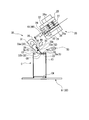
- the temporary attachment device 50 is moved in the direction indicated by the arrow M3, and as shown in FIG. 10, the temporary attachment device 50 is rotated in the direction indicated by the arrow M4.
- the tip 51 of the tacking device 50 (tacking iron) is brought into contact with the first end Sa of the tab material S from above and heated to cover the first end Sa of the tab material S held by the tab transfer 32.
- the temporary attachment position S3 with which the tip 51 of the temporary attachment iron abuts in the temporary attachment device 50 is, for example, a position between the opening C6 and the embossed portion S2 as shown in FIGS.
- suction ending step the operation of a suction device (suction means) such as a decompression pump (not shown) in the transfer device 30 is stopped, the plurality of suction holes 35 are set to normal pressure, and the tab material S is applied to the upper surface 32a of the tab transfer 32. The adsorption of the second end Sb is released.
- suction device suction means
- decompression pump not shown
- a rotation drive device (rotation drive means) (not shown) in the transfer device 30 is operated to rotate the tab transfer 32 in the direction indicated by the arrow M6 from the attachment position toward the cutting position. Rotate around axis 31.
- the holding end process simultaneously with the turning operation of the tab transfer 32, the holding of the second end Sb of the tab material S between the tab clip 33 and the upper surface 32a of the tab transfer 32 in the transfer device 30 is released.
- the tab material S is pressed by the tip 51 of the tacking iron in the tacking device 50, and is kept sandwiched until the flip-up operation in the tab transfer 32, that is, the operation of raising the tab material S is started.
- the force that the tacking iron holds down> the holding force of the tab clip 33 there is a relationship of “the force that the tacking iron holds down> the holding force of the tab clip 33”, and the tab transfer state of the tab material S is canceled by the jumping-up operation of the tab transfer 32.
- the heating of the tip 51 of the tacking iron in the tacking device 50 is released, and the tacking device 50 is rotated in the direction opposite to the direction indicated by the arrow M4 shown in FIG. Then, the liquid paper container C is moved in the moving direction M from the attaching position which is the lower position of the tab transfer 32 by the conveyor 60. At the same time, the temporary attachment device 50 is moved in the direction indicated by the arrow M5.
- the liquid paper container C temporarily attached with the tab material S becomes a product through a content filling process, a sealing process for bonding the tab material S, and the like.
- the tab clip 33 presses the upper surface 32a of the tab transfer 32 by the biasing member 34, and the tab material cut by the cutting process with the plurality of suction holes 35 set to negative pressure.
- the second end Sb of S is sandwiched and firmly held between the tab clip 33 and the upper surface 32a of the tab transfer 32. Therefore, even if the tab material S is pulled by the cutting device 20, such as when the tab material S is caught at the edge of the lower base portion 26, the tab material S does not deviate from the held position. Thereby, generation
- the tab material S has irregularities, such as embossing, and easily catches on the cutting device 20, the tab material S is prevented from being displaced from the held position, so that the tab material S is securely attached. It is possible to transport the liquid paper container C to the attachment position.
- FIG. 12 is a schematic front view showing the transport apparatus in the present embodiment. This embodiment is different from the first embodiment described above in that a plurality of liquid paper containers C can be processed at the same time, and other corresponding components are denoted by the same reference numerals and the description thereof is omitted. Omitted.
- the transport unit 1A, the transport unit 1B, and the transport unit 1C have the same configuration as the corresponding configuration of the transport device 1 according to the first embodiment described above.
- the tabs can be simultaneously provided on a plurality of liquid paper containers C in accordance with the number of the transport units 1A, 1B, and 1C provided.
- the material S can be transported and temporarily attached.
- FIG. 17 is a perspective view showing the transfer device 130 in the transport device according to the present embodiment.
- the present embodiment differs from the first embodiment described above in that a transfer device 130 uses a guide portion 140 provided with a roller 100 as shown in FIG.
- a transfer device 130 uses a guide portion 140 provided with a roller 100 as shown in FIG.
- a roller 100 is provided in the guide unit 40 of the transfer device according to the first embodiment instead of the clip pusher 36.
- the roller 100 is provided in the guide part 140, and is provided so that the outer surface of the roller 100 is in contact with the upper surface of the tab clip 133.
- the roller 100 is provided so as to have a rotation axis parallel to the upper surface of the tab clip 133. That is, like the rotation shaft 131 of the transfer device 130, the roller 100 is provided to rotate about a substantially horizontal axis.
- the roller 100 is configured to be rotatable in accordance with the rotation operation of the tab transfer 132 and the tab clip 133 in the transfer device 130.
- the roller 100 is similar to the clip pusher 36 of the transfer device according to the first embodiment. It is possible to switch the second end Sb) of the tab material fed from the holding state to the open state.
- the guide part 140 in this embodiment has the same configuration as that of the guide part 40 according to the first embodiment, except that the roller 100 is provided.
- the roller 100 rotates when the tab transfer 132 and the tab clip 133 rotate in the transfer device 130. Therefore, the stress between the roller 100 and the tab clip 133 is relieved, and the wear of the tab clip 133 is reduced.
- the roller 100 may be formed of resin, and may have a configuration in which a resin layer is provided so as to cover the surface of a shaft body that serves as a rotation shaft of the roller 100. If the material of the roller 100 is resin, for example, even if the tab clip 133 is made of metal, the contact surface between the roller 100 and the tab clip 133 comes into contact with the resin and metal. Is suppressed.
- the resin used for the roller 100 is not particularly limited as long as the roller 100 can rotate between the guide portion 140 and the tab clip 133, and can be appropriately selected depending on the application.
- the resins used for the roller 100 PEEK resin, fluorine resin, ultrahigh molecular weight polyethylene, and the like are preferable.
- PEEK resin is particularly preferable. If the resin used for the roller 100 is a PEEK resin, the roller 100 is likely to rotate uniformly between the guide portion 140 and the tab clip 133. Further, if the resin used for the roller 100 is PEEK resin, even if the roller 1100 rotates and wears, the entire roller is likely to be evenly worn (a part of the roller that is locally worn is less likely to occur). From the viewpoint of consumability
- the roller 100 may be removable from the guide part 140.
- the case where the roller 100 is detachable from the guide portion 140 is, for example, a case where the roller 100 has a screwing structure in which the rotation shaft of the roller is fixed by a bolt 101. In this case, since the rotating shaft has a screwing structure, the roller 100 can be easily replaced when the roller 100 is consumed.
- the tab clip 133 is less worn due to the presence of the roller 100, and the durability of the tab clip 133 is improved. Therefore, the stability of tab conveyance is improved, and the conveyance device is long-term. Ensures stability and durability during long-term use.
- the rollers 100 can be easily replaced, so that the maintenance of the transport device is also easy.
- the tab material S was temporarily attached to the liquid paper container C by the transport device 1. At this time, the tab material that was embossed and the tab material that was not embossed were compared. Specifically, as shown in FIG. 14, when caught at the outlet T4 of the cutting device 20, as indicated by an arrow T3 in FIG. 13, the tab material S does not shift and is generated on the upper surface 32a of the tab transfer 32. The required resistance was measured.
- the height (distance) T5 between the one end Sa and the upper surface of the lid member C3 was changed.
- the resistance force T3 was 0.11N.
- the resistance force T3 was 0.75N.
- the resistance force T3 was 0.87N. The resistance was measured using a force gauge (Model: ZTA-500N manufactured by Imada Co., Ltd.).
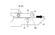
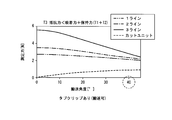
- FIG. 16A is a graph showing a state where the relationship between the suction force T1 and the resistance force T3 of the suction portion 35 when the tab clip 33 is not used varies depending on the rotation angle from the cutting position of the tab transfer 32.
- FIG. 16B shows a state in which the relationship between the suction force T1 of the suction portion 35 and the holding force T2 of the tab clip 33 and the resistance force T3 when the tab clip 33 is used varies depending on the rotation angle of the tab transfer 32 from the cutting position. It is the graph which showed.
Landscapes
- Engineering & Computer Science (AREA)
- Mechanical Engineering (AREA)
- Labeling Devices (AREA)
- Closing Of Containers (AREA)
- Auxiliary Devices For And Details Of Packaging Control (AREA)
Abstract
L'invention concerne un dispositif de transport, lequel dispositif comprend : un dispositif moteur pour déplacer un récipient en papier pour un liquide, ayant un élément de fût cylindrique et un élément de couvercle avec une partie de bord périphérique externe qui s'élève dans la direction vers le haut, le récipient étant déplacé tandis qu'il est vertical, de telle sorte que l'élément de couvercle est disposé à la surface supérieure du récipient en papier pour un liquide ; un dispositif d'introduction pour introduire un élément de patte en feuille ; un dispositif de coupe pour couper l'élément de patte en feuille introduit à partir du dispositif d'introduction, de façon à former ainsi un élément de patte ayant un premier bord et un second bord ; un dispositif de transfert pour maintenir le second bord de l'élément de patte, et apte à faire tourner l'élément de patte autour d'un axe globalement horizontal à partir d'un emplacement de coupe au-dessus de l'élément de couvercle jusqu'à un emplacement d'adhérence au niveau de la surface supérieure de l'élément de couvercle ; et un dispositif d'attachement préliminaire pour attacher de façon préliminaire la première extrémité de l'élément de patte, ayant tourné jusqu'à l'emplacement d'adhérence, à l'élément de couvercle.
Priority Applications (2)
| Application Number | Priority Date | Filing Date | Title |
|---|---|---|---|
| JP2016570695A JP6760082B2 (ja) | 2015-01-21 | 2016-01-21 | 搬送装置 |
| CN201680006171.2A CN107108051B (zh) | 2015-01-21 | 2016-01-21 | 搬运装置 |
Applications Claiming Priority (2)
| Application Number | Priority Date | Filing Date | Title |
|---|---|---|---|
| JP2015009691 | 2015-01-21 | ||
| JP2015-009691 | 2015-01-21 |
Publications (1)
| Publication Number | Publication Date |
|---|---|
| WO2016117635A1 true WO2016117635A1 (fr) | 2016-07-28 |
Family
ID=56417167
Family Applications (1)
| Application Number | Title | Priority Date | Filing Date |
|---|---|---|---|
| PCT/JP2016/051674 Ceased WO2016117635A1 (fr) | 2015-01-21 | 2016-01-21 | Dispositif de transport |
Country Status (3)
| Country | Link |
|---|---|
| JP (1) | JP6760082B2 (fr) |
| CN (1) | CN107108051B (fr) |
| WO (1) | WO2016117635A1 (fr) |
Cited By (1)
| Publication number | Priority date | Publication date | Assignee | Title |
|---|---|---|---|---|
| WO2017090331A1 (fr) * | 2015-11-27 | 2017-06-01 | 凸版印刷株式会社 | Dispositif de distribution de matériau de languette et procédé de distribution de matériau de languette |
Citations (3)
| Publication number | Priority date | Publication date | Assignee | Title |
|---|---|---|---|---|
| US3908340A (en) * | 1974-03-25 | 1975-09-30 | Anderson Bros Mfg Co | Apparatus for feeding and applying individual lids to containers |
| JPH08224627A (ja) * | 1995-02-03 | 1996-09-03 | Ruediger Haaga Gmbh | 可撓性の容器壁の開口に対する密封部材 |
| JP2003252301A (ja) * | 2002-02-27 | 2003-09-10 | Gunze Ltd | キャップシール装着装置 |
Family Cites Families (6)
| Publication number | Priority date | Publication date | Assignee | Title |
|---|---|---|---|---|
| DE3905469A1 (de) * | 1989-02-22 | 1990-08-23 | Windmoeller & Hoelscher | Vorrichtung zum aufbringen von mit einem leimauftrag versehenen verstaerkungszetteln auf eine mit querperforationen versehene bahn |
| DE4042178C2 (de) * | 1990-01-12 | 2002-04-25 | Focke & Co | Vorrichtung zum Anbringen von Etiketten oder dergleichen an Packungen |
| SE466952B (sv) * | 1990-09-13 | 1992-05-04 | Tetra Pak Holdings Sa | Anordning foer applicering av en materialremsa paa en foerpackningsmaterialbana |
| SE514723C2 (sv) * | 1996-11-01 | 2001-04-09 | Tetra Laval Holdings & Finance | Sätt och anordning för att applicera ett täckskikt över en hällöppning |
| JP3252349B2 (ja) * | 1997-10-17 | 2002-02-04 | 英則 森田 | パッキング装置 |
| JP4965113B2 (ja) * | 2005-11-22 | 2012-07-04 | パナソニック株式会社 | 接合シート貼付装置及び方法 |
-
2016
- 2016-01-21 WO PCT/JP2016/051674 patent/WO2016117635A1/fr not_active Ceased
- 2016-01-21 CN CN201680006171.2A patent/CN107108051B/zh not_active Expired - Fee Related
- 2016-01-21 JP JP2016570695A patent/JP6760082B2/ja active Active
Patent Citations (3)
| Publication number | Priority date | Publication date | Assignee | Title |
|---|---|---|---|---|
| US3908340A (en) * | 1974-03-25 | 1975-09-30 | Anderson Bros Mfg Co | Apparatus for feeding and applying individual lids to containers |
| JPH08224627A (ja) * | 1995-02-03 | 1996-09-03 | Ruediger Haaga Gmbh | 可撓性の容器壁の開口に対する密封部材 |
| JP2003252301A (ja) * | 2002-02-27 | 2003-09-10 | Gunze Ltd | キャップシール装着装置 |
Cited By (2)
| Publication number | Priority date | Publication date | Assignee | Title |
|---|---|---|---|---|
| WO2017090331A1 (fr) * | 2015-11-27 | 2017-06-01 | 凸版印刷株式会社 | Dispositif de distribution de matériau de languette et procédé de distribution de matériau de languette |
| JPWO2017090331A1 (ja) * | 2015-11-27 | 2018-09-20 | 凸版印刷株式会社 | タブ材受渡し装置及びタブ材受渡し方法 |
Also Published As
| Publication number | Publication date |
|---|---|
| JPWO2016117635A1 (ja) | 2017-11-24 |
| CN107108051A (zh) | 2017-08-29 |
| JP6760082B2 (ja) | 2020-09-23 |
| CN107108051B (zh) | 2019-09-10 |
Similar Documents
| Publication | Publication Date | Title |
|---|---|---|
| CN1329180C (zh) | 轮胎结构构件制造方法以及实施该方法的装置 | |
| US8544519B2 (en) | Tack labeler | |
| TWI515120B (zh) | 包含平板壓機的打印機 | |
| US6666005B1 (en) | Packaging method and packaging apparatus | |
| EP3718908B1 (fr) | Dispositif de banderolage et d'emballage | |
| CN101223093A (zh) | 用于拼接标签带的装置和方法 | |
| CN108925134A (zh) | 用于加工包装材料的幅材的设备和方法以及包装材料 | |
| KR101428379B1 (ko) | 상부 개구형 박스의 제조장치 | |
| JP2004276951A (ja) | 封緘装置 | |
| KR20200037139A (ko) | 블리스터 포장기 | |
| US5816993A (en) | Apparatus and method for attaching carrying handles to bags | |
| JPWO2016117635A1 (ja) | 搬送装置 | |
| KR101639050B1 (ko) | 성질과 평량이 다른 지류의 스파이크 타입 고속 합지장치 | |
| CN204054770U (zh) | 一种纸袋粘胶钩机 | |
| US20080078497A1 (en) | Method and Means of Applying Adhesive Tape | |
| CN211389282U (zh) | 一种送带机构 | |
| TW201408565A (zh) | 用於處理板件之具有運輸裝置之餽送桌的機器 | |
| JP7553212B2 (ja) | テープ供給装置およびテープ供給方法 | |
| WO2014178143A1 (fr) | Dispositif de collage de film de renfort | |
| JP2000025130A (ja) | 製袋機 | |
| CN220391736U (zh) | 一种适用于无底纸标签的自动贴标机 | |
| BE1003743A6 (fr) | Un procede pour la production de matiere en feuilles. | |
| JP7601584B2 (ja) | ラベル貼付装置およびラベル貼付方法 | |
| CN215794743U (zh) | 覆膜机的板型材上料装置 | |
| JPS6016489Y2 (ja) | シ−ルテ−プ貼着装置 |
Legal Events
| Date | Code | Title | Description |
|---|---|---|---|
| 121 | Ep: the epo has been informed by wipo that ep was designated in this application |
Ref document number: 16740242 Country of ref document: EP Kind code of ref document: A1 |
|
| ENP | Entry into the national phase |
Ref document number: 2016570695 Country of ref document: JP Kind code of ref document: A |
|
| NENP | Non-entry into the national phase |
Ref country code: DE |
|
| 122 | Ep: pct application non-entry in european phase |
Ref document number: 16740242 Country of ref document: EP Kind code of ref document: A1 |