WO2016120942A1 - Adsorbant pour adoucisseur d'eau, adoucisseur d'eau, et dispositif de production d'eau électrolysée - Google Patents
Adsorbant pour adoucisseur d'eau, adoucisseur d'eau, et dispositif de production d'eau électrolysée Download PDFInfo
- Publication number
- WO2016120942A1 WO2016120942A1 PCT/JP2015/006380 JP2015006380W WO2016120942A1 WO 2016120942 A1 WO2016120942 A1 WO 2016120942A1 JP 2015006380 W JP2015006380 W JP 2015006380W WO 2016120942 A1 WO2016120942 A1 WO 2016120942A1
- Authority
- WO
- WIPO (PCT)
- Prior art keywords
- water
- adsorbent
- metal ion
- water softener
- oxidized
- Prior art date
- Legal status (The legal status is an assumption and is not a legal conclusion. Google has not performed a legal analysis and makes no representation as to the accuracy of the status listed.)
- Ceased
Links
Images


Classifications
-
- B—PERFORMING OPERATIONS; TRANSPORTING
- B01—PHYSICAL OR CHEMICAL PROCESSES OR APPARATUS IN GENERAL
- B01J—CHEMICAL OR PHYSICAL PROCESSES, e.g. CATALYSIS OR COLLOID CHEMISTRY; THEIR RELEVANT APPARATUS
- B01J20/00—Solid sorbent compositions or filter aid compositions; Sorbents for chromatography; Processes for preparing, regenerating or reactivating thereof
- B01J20/02—Solid sorbent compositions or filter aid compositions; Sorbents for chromatography; Processes for preparing, regenerating or reactivating thereof comprising inorganic material
- B01J20/20—Solid sorbent compositions or filter aid compositions; Sorbents for chromatography; Processes for preparing, regenerating or reactivating thereof comprising inorganic material comprising free carbon; comprising carbon obtained by carbonising processes
-
- B—PERFORMING OPERATIONS; TRANSPORTING
- B01—PHYSICAL OR CHEMICAL PROCESSES OR APPARATUS IN GENERAL
- B01J—CHEMICAL OR PHYSICAL PROCESSES, e.g. CATALYSIS OR COLLOID CHEMISTRY; THEIR RELEVANT APPARATUS
- B01J20/00—Solid sorbent compositions or filter aid compositions; Sorbents for chromatography; Processes for preparing, regenerating or reactivating thereof
- B01J20/30—Processes for preparing, regenerating, or reactivating
- B01J20/34—Regenerating or reactivating
-
- B—PERFORMING OPERATIONS; TRANSPORTING
- B01—PHYSICAL OR CHEMICAL PROCESSES OR APPARATUS IN GENERAL
- B01J—CHEMICAL OR PHYSICAL PROCESSES, e.g. CATALYSIS OR COLLOID CHEMISTRY; THEIR RELEVANT APPARATUS
- B01J39/00—Cation exchange; Use of material as cation exchangers; Treatment of material for improving the cation exchange properties
- B01J39/08—Use of material as cation exchangers; Treatment of material for improving the cation exchange properties
- B01J39/24—Carbon, coal or tar
-
- C—CHEMISTRY; METALLURGY
- C01—INORGANIC CHEMISTRY
- C01B—NON-METALLIC ELEMENTS; COMPOUNDS THEREOF; METALLOIDS OR COMPOUNDS THEREOF NOT COVERED BY SUBCLASS C01C
- C01B32/00—Carbon; Compounds thereof
- C01B32/05—Preparation or purification of carbon not covered by groups C01B32/15, C01B32/20, C01B32/25, C01B32/30
-
- C—CHEMISTRY; METALLURGY
- C02—TREATMENT OF WATER, WASTE WATER, SEWAGE, OR SLUDGE
- C02F—TREATMENT OF WATER, WASTE WATER, SEWAGE, OR SLUDGE
- C02F1/00—Treatment of water, waste water, or sewage
- C02F1/28—Treatment of water, waste water, or sewage by sorption
-
- C—CHEMISTRY; METALLURGY
- C02—TREATMENT OF WATER, WASTE WATER, SEWAGE, OR SLUDGE
- C02F—TREATMENT OF WATER, WASTE WATER, SEWAGE, OR SLUDGE
- C02F1/00—Treatment of water, waste water, or sewage
- C02F1/42—Treatment of water, waste water, or sewage by ion-exchange
-
- C—CHEMISTRY; METALLURGY
- C02—TREATMENT OF WATER, WASTE WATER, SEWAGE, OR SLUDGE
- C02F—TREATMENT OF WATER, WASTE WATER, SEWAGE, OR SLUDGE
- C02F1/00—Treatment of water, waste water, or sewage
- C02F1/46—Treatment of water, waste water, or sewage by electrochemical methods
Definitions
- the present invention relates to an adsorbent for a water softener, a water softener, and an electrolyzed water production apparatus.
- hypochlorous acid water which is a kind of acidic electrolyzed water, has strong bactericidal properties but is stable, and unlike hypochlorite, it has no residue, so it is expected to be widely used in food, hygiene, agriculture, etc.
- the acidic electrolyzed water production apparatus includes an electrolytic cell and an electrode provided in the electrolytic cell.
- an electrolyzed water production apparatus having a three-chamber type electrolytic cell has been proposed.
- the inside of the electrolytic cell is divided into three chambers, an intermediate chamber, and an anode chamber and a cathode chamber located on both sides of the intermediate chamber, by a cation exchange membrane and an anion exchange membrane.
- a positive electrode and a negative electrode are provided as a pair of electrodes, respectively.
- the electrode there may be used a porous electrode in which a large number of through holes are processed on a metal plate base material by expanding, etching, or punching.
- salt water is passed through the intermediate chamber, and water is circulated through the anode chamber and the cathode chamber, respectively.
- hypochlorite water and acidic electrolyzed water of hydrochloric acid are generated in the anode chamber, and hydrogen and sodium hydroxide water are generated in the cathode chamber. Is generated.
- the produced hypochlorous acid water is used as sterilizing / disinfecting water, and sodium hydroxide water is used as washing water.
- An object of the present invention is to provide an electrolyzed water production apparatus equipped with a water softener that can be efficiently softened and easily regenerated, an adsorbent for a water softener suitable for the water softener, and a water softener using the same. is there.
- the adsorbent for a water softener contains oxidized graphene or oxidized graphite having a carboxyl group and a phenolic hydroxyl group.
- the adsorbent for water softener adsorbs at least a part of calcium ions at a pH of 7 from a solution containing calcium ions, and at least a part of the calcium ions adsorbed in an acidic solution in the range of pH 2 to 6. Is detached.
- the water softener according to the embodiment includes the water softener adsorbent according to the present embodiment.
- An electrolyzed water production apparatus includes an electrolytic cell having at least an anode chamber and a cathode chamber, a pair of electrodes respectively disposed in the anode chamber and the cathode chamber, and a power source for applying a voltage between the electrodes
- a water supply unit for supplying water to the anode chamber and the cathode chamber, a salt water supply unit for supplying salt water to the electrolytic cell, and a metal for removing metal ions in the water supplied to the electrolytic cell in the water supply unit
- FIG. 1 is a conceptual diagram of an electrolyzed water production apparatus according to an embodiment.
- FIG. 2 is a modification of the electrolyzed water production apparatus of the embodiment of FIG.
- FIG. 3 is a schematic structural diagram of oxidized graphene that is the adsorbent according to the embodiment.
- 4 is a graph showing the pH dependence of the zeta potential of oxidized graphene in Example 1.
- FIG. 5 is a conceptual diagram of a metal ion removing unit according to the twelfth embodiment.
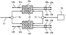
- FIG. 6 is a conceptual diagram including a metal ion removing unit in Examples 13 to 15.
- each drawing is a schematic diagram for promoting the embodiment and its understanding, and its shape, dimensions, ratio, etc. are different from the actual device, but these are considered in consideration of the following description and known techniques.
- the design can be changed as appropriate.
- the electrode is drawn on a plane, but it may be bent according to the shape of the electrode unit or may be cylindrical.
- the electrolyzed water producing apparatus includes an electrolytic cell having at least an anode chamber and a cathode chamber, a pair of electrodes respectively disposed in the anode chamber and the cathode chamber, and a voltage for applying a voltage between the electrodes.
- a power supply a water supply unit that supplies water to the anode chamber and the cathode chamber, a salt water supply unit that supplies salt water to the electrolytic cell, and metal ion removal that removes metal ions in the water supplied to the electrolytic cell in the water supply unit
- a regenerator that regenerates the metal ion removal unit by flowing acidic electrolyzed water into the metal ion removal unit.
- FIG. 1 is a diagram schematically showing an example of an electrolyzed water production apparatus according to this embodiment.
- the electrolyzed water production apparatus 10a shown in FIG. 1 includes a three-chamber electrolyzer 11, a metal ion removing unit 12, a salt water tank 13, and an acidic electrolyzed water tank 14.
- a three-chamber type electrolytic cell will be described as an example, but the electrolytic cell may be a two-chamber type.
- the electrolytic cell 11 is formed in a flat rectangular box shape, and the inside thereof is composed of three chambers: a cathode chamber 15, an anode chamber 16, and an intermediate chamber 17 sandwiched between the cathode chamber 15 and the anode chamber 16.
- the negative electrode 21 and the positive electrode 22 are disposed as a pair of electrodes in the cathode chamber 15 and the anode chamber 16, respectively.
- the porous diaphragm 23 partitions the cathode chamber 15 and the intermediate chamber 17, and the porous diaphragm 24 is provided so as to partition the anode chamber 16 and the intermediate chamber 17.
- the porous diaphragm 23 preferably has a cation exchange function, and the porous diaphragm 24 preferably has an anion exchange function.
- the electrolyzed water production apparatus 10 a includes a power supply 30 for applying a voltage to the negative electrode 21 and the positive electrode 22. Furthermore, an ammeter or a voltmeter may be provided. A liquid flow path may be provided in the cathode chamber 15 and the anode chamber 16.
- the electrolyzed water production apparatus 10a of the present embodiment includes a water supply line L1 to the metal ion removal unit 12, a water supply line L2 from the metal ion removal unit 12 to the anode chamber 16, and a metal ion removal unit 12 to the cathode.
- a water discharge line L9 is provided.
- the metal ion removing unit 12 contains an adsorbent 51.
- the adsorbent 51 include an adsorbent capable of adsorbing and removing metal ions in water supplied from L1.
- This adsorbent can be regenerated by circulating acidic electrolyzed water generated by electrolysis, and adsorbs at least some calcium ions from this water when the water supplied from the supply line L1 has a pH of 7, It preferably has an action of desorbing at least some of the calcium ions adsorbed to the acidic electrolyzed water supplied from the supply line L5.
- the supply line L ⁇ b> 5 is used as a regeneration unit, and the acidic electrolyzed water generated thereby can be supplied to the metal ion removal unit 12.
- a normal column fixed bed, a precipitation tank, or a fluidized bed can be used.
- a fluidized bed is preferable.
- a sedimentation tank is preferable.
- a fixed bed is preferable.
- the metal ion removal unit 12 mainly functions as a so-called water softener that removes hardness components in water.
- the electrolyzed water production apparatus 10a of this embodiment can use the basic structure of a conventional electrolyzed water production apparatus and the elements constituting it. That is, the water supply unit may be capable of supplying water to the electrolytic cell 11 through the supply line L1, and examples of the water include tap water, industrial water, city water, and the like. Further, the salt water supply unit supplies a salt water tank 13 capable of storing salt water containing sodium chloride, supplies this salt water to the intermediate chamber 17, stores the discharged salt water again in the salt water tank 13, and supplies it again to the intermediate chamber 17. And a circulation line L4 that can be formed. At this time, in the salt water tank 13, the salt concentration in the salt water is adjusted so that the operation of the apparatus can be continuously performed.
- the characteristic structure in this embodiment is that the generated acidic electrolyzed water can be used for the regeneration of the metal ion removing unit 12.
- the generated acidic electrolyzed water is used as a regenerating solution.
- the acid electrolyzed water for regeneration is prepared separately and all the electrolyzed acidic electrolyzed water generated by electrolysis is supplied to the use point. May be.
- the acidic electrolyzed water is preferably one containing hypochlorous acid as a main component (such as hypochlorous acid water).
- FIG. 2 is a diagram schematically showing an electrolyzed water production apparatus 10b in which a salt water supply line L12 from the salt water tank 13 to the metal ion removing unit 12 is further installed in addition to FIG. Thereby, not only acidic electrolyzed water but also salt water can be used for regeneration of the metal ion removing unit 12. Thereby, when it is necessary to use a large amount of acidic electrolyzed water, the metal ion removing unit 12 can be regenerated using the raw salt water.
- the treated water cannot be supplied to the electrolytic cell 11 when the adsorbent in the metal ion removing unit 12 is regenerated.
- two or more metal ion removing units 12 may be installed in parallel, and one may perform water softening treatment and the other may perform adsorbent regeneration processing.
- it can process continuously by performing a water softening process and a regeneration process in parallel (in one metal ion removal unit, a water softening process and a regeneration process are performed alternately). Even if the time required for water softening and regeneration is different, it is possible to easily cope with three or more metal ion removal units, and the amount of adsorbent can be reduced, so the overall volume of the device can be reduced. It may become.
- the adsorbent for water softeners according to the embodiment is an adsorbent for water softeners containing oxidized graphene or oxidized graphite having a carboxyl group and a phenolic hydroxyl group.
- Oxidized graphite is obtained by oxidizing graphite, and oxidized graphene may be obtained by oxidizing graphene or by highly oxidizing and exfoliating graphite. This oxidation inevitably becomes a compound having a carboxyl group or a phenolic hydroxyl group.
- FIG. 3 shows a schematic structure of oxidized graphene.
- This water softener adsorbent preferably has a property of adsorbing calcium ions at pH 7 and desorbing at least some of the calcium ions in the pH 2 to 6 region.
- the pH at which this calcium ion desorption characteristic is manifested is preferably pH 3 to 6, and more preferably pH 4 to 6.
- this recovery amount is more preferably 80% or more, and further preferably 90% or more.
- this recovery amount is more preferably 25% or more, and further preferably 40% or more.
- the pKa values of various oxidized aromatic compounds are 2.78 for salicylic acid (o-hydroxybenzoic acid), 2.80 for 1,2,3-benzenetricarboxylic acid, 4.20, 5.87, phthalic acid 2.98, 5.28, benzoic acid 4.2, catechol 9.12, 12.08, phenol 9.95, ranging from pH 3 to pH 12 To do. Therefore, an adsorbent formed by oxidizing graphene or graphite to form many carboxyl groups and phenolic hydroxyl groups exhibits at least one existing in treated water in a neutral region of pH 7 due to a behavior similar to the above aromatic compound. Part of calcium ions can be adsorbed, and at least some of the adsorbed calcium ions in the region of pH 2 to 6 can be desorbed.
- Oxidized graphene and oxidized graphite are macromolecules that can easily be aggregated and can be packed stably in a column, or can be easily supported on a carrier such as inorganic oxide beads or polymer beads.
- the carrier used at this time preferably has an average primary particle size of 100 ⁇ m or more and 5 mm or less. When the average primary particle size of the carrier is 100 ⁇ m or more and 5 mm or less, both the high filling rate of the adsorbent and the ease of water flow can be achieved. When the average primary particle size is less than 100 ⁇ m, the packing rate of the adsorbent into the column or the like becomes too high, and the ratio of voids decreases, so that it becomes difficult for water to pass through.
- a preferable carrier has an average primary particle size of 100 ⁇ m or more and 2 mm or less, and more preferably 300 ⁇ m or more and 1 mm or less.
- the average particle diameter of the carrier can be measured by a sieving method. Specifically, it can be measured by sieving using a plurality of sieves having an opening of 100 ⁇ m to 5 mm in accordance with JIS Z 8901: 2006 “Test Powder and Test Particles”.
- the adsorbent preferably has a zeta potential at pH 7 that is negative and shifts in a positive direction from pH 2 to 6 above the zeta potential at pH 7.
- the shift amount of the zeta potential at pH 2 is preferably 50% to 100% of the absolute value of the zeta potential at pH 7. If this shift amount is less than 50%, the release of calcium ions is not sufficient, and if it is more than 100%, the absolute value at pH 7 is often small, and calcium ions or the like cannot be sufficiently adsorbed.
- This shift amount is preferably 60% to 90%, and more preferably 70% to 85%.
- the electrolyzed water of pH 2 to 6 is known as acidic electrolyzed water among the electrolyzed water, and has strong bactericidal properties and is useful. If the adsorbent is capable of releasing calcium ions in this pH range, it can be used as regenerated water for the adsorbent in the water softener while producing it as water for sterilization, and it is preferable that no other regenerant be prepared. In order to make this electrolyzed water more acidic, the pH is set to about 1, which is not preferable because chlorine gas is generated.
- the adsorbent can adsorb and regenerate not only calcium ions but also multivalent ions such as magnesium ions, iron ions, manganese ions, and copper ions. It can also adsorb and regenerate rare metals such as dysprosium and neodymium, and cations containing uranium and plutonium.
- the adsorbent preferably contains an inorganic oxide having a zeta potential of 0 or negative at pH 7 and a positive zeta potential of pH 2 to 6.
- inorganic oxide can interact with oxidized graphene and graphite and stably hold them, and facilitates desorption by electrostatic repulsion with calcium ions in weakly acidic regions.
- titanium oxide, zirconium oxide, aluminum oxide, zircon and the like are preferable.
- the zeta potential may be measured as follows, for example. First, after thoroughly stirring the sample for each container, about 0.005-0.05 g is collected in a 100 mL beaker, about 50 mL of pure water is added, and dispersion treatment is performed by ultrasonic irradiation (100 W, 3 minutes). Next, the measurement sample solution is adjusted to a predetermined pH using an aqueous sodium hydroxide solution and hydrochloric acid. The prepared solution is measured by electrophoresis (for example, using Zetasizer Nano ZS (trade name) manufactured by Malvern). The capillary cell uses a disposable zeta potential measurement cell, and the refractive index, dielectric constant, and viscosity of the solvent are set to the values of water.
- the adsorbent preferably contains magnetic particles.
- the adsorbent can be stably held in the metal ion removing unit, and the adsorbent can be easily exchanged by using magnetic force.
- the magnetic particles are preferably iron oxide or iron from the viewpoint of safety when eluted.
- oxidized graphene and oxidized graphite have functional groups such as a carboxyl group and a phenolic hydroxyl group as shown in FIG. 3, and are basically composed of carbon, oxygen, and hydrogen.
- the oxidized graphene or oxidized graphite preferably has a ratio of carbon atoms to oxygen atoms of 1 to 0.1 to 1 to 0.7. If this ratio is smaller than 1: 0.1 (there are few oxygen atoms), there is a possibility that sufficient adsorption ability cannot be obtained. If this ratio is larger than 1 to 0.7 (there are many oxygen atoms), calcium ions are not sufficiently desorbed in the pH range of 2 to 6, and the regeneration operation with acidic electrolyzed water may be insufficient. There is. This ratio is more preferably 1 to 0.2 to 1 to 0.5, and even more preferably 1 to 0.25 to 1 to 0.4.
- the oxidized graphene may be a single layer or a multilayer of 2 to 10 layers. Preferably it is 5 layers or less, More preferably, it is 3 layers or less.
- graphene has a single-layer structure, but in this specification, oxidized graphene includes a multilayer structure in which single-layer structures are stacked.
- the oxidized graphene having a multilayer structure is different from the oxidized graphite described later in that the number of stacked layers is small and an oxidation site is also provided in the multilayered interior.
- the shortest diameter of the graphene oxide sheet is preferably 0.1 ⁇ m to 50 ⁇ m.
- the dispersibility of the graphene oxide sheet is originally good, but if the shortest diameter is smaller than 0.1 ⁇ m, the cohesiveness becomes too small and it becomes difficult to carry on the carrier. On the other hand, when it is larger than 50 ⁇ m, the dispersibility is lowered and the active edge per mass is reduced, so that the adsorption performance is lowered.
- This shortest diameter is more preferably 0.5 ⁇ m to 10 ⁇ m, and even more preferably 0.7 ⁇ m to 7 ⁇ m.
- Oxidized graphite has a graphite structure, and its edge and surface are mainly oxidized.
- the longest diameter is preferably 0.5 ⁇ m to 100 ⁇ m.
- Oxidized graphite has a high cohesiveness from the beginning, but if the longest diameter is smaller than 0.5 ⁇ m, the cohesiveness may be lowered. On the other hand, if it is larger than 100 ⁇ m, the dispersibility becomes too small and the active edge per mass may be reduced.
- the longest diameter is preferably 1 ⁇ m to 50 ⁇ m, more preferably 2 ⁇ m to 20 ⁇ m.
- the size of oxidized graphene or oxidized graphite can be directly measured using a scanning electron microscope or an atomic force microscope. In that case, since measurement is difficult in the aggregated state, it is preferable to measure by applying a diluted solution or adjusting the pH to eliminate the aggregated state and then applying the solution on the substrate. If no carrier is used, the particle size can also be measured by laser scattering.
- oxidized graphene and oxidized graphite may contain nitrogen atoms.
- a nitrogen atom having excellent coordination ability, the adsorption ability for metal ions is increased.
- the ratio of the carbon atom to the nitrogen atom is preferably from 1: 0.001 to 1: 0.3. If this ratio is less than 1 to 0.001, the effect is scarcely, and if it is more than 1 to 0.3, the amount of oxygen decreases, so the adsorptive capacity also decreases. This ratio is more preferably 1 to 0.01 to 1 to 0.1. More preferably, it is 1 to 0.02 to 1 to 0.08.
- Nitrogen atoms can be contained by using a chemical solution that becomes a nitrogen source such as sodium nitrate when graphene or graphite is oxidized, and graphene oxide or graphite oxide is treated with ammonia, hydrazine, or the like. Can be included.
- the amount of carbon, nitrogen and oxygen can be determined by chemical elemental analysis. Alternatively, it can be determined by X-ray photoelectron spectroscopy (XPS).
- Oxidized graphene and oxidized graphite can be produced, for example, by the following method.
- the mixture of concentrated sulfuric acid and sodium nitrate is cooled, and graphite powder is gradually added to the mixture at around 5 ° C.
- potassium permanganate powder is gradually added to the mixed solution while cooling.
- An oxidation reaction occurs in the mixed solution, and the reaction solution rises to about 10 ° C.
- water is gradually added and heated to reflux for 30 minutes.
- hydrogen peroxide is added dropwise.
- the resulting reaction mixture is centrifuged to recover the precipitate.
- the precipitate is washed several times with dilute hydrochloric acid, centrifuged, and then dried by heating under vacuum to obtain graphene oxide.
- Oxidized graphite can be produced under milder conditions. That is, in the production of oxidized graphene, graphene is formed by heating and refluxing in the presence of an oxidizing agent, but when obtaining oxidized graphite, the amount of oxidizing agent is reduced or heating is performed. The step of refluxing may be omitted or performed.
- the degree of oxidation can be increased by increasing the amount of oxidizing agent used, increasing the reaction temperature, and increasing the time.
- the size can be controlled by the size of the raw graphite.
- the number of oxidized graphene layers can be reduced by increasing the reflux time during synthesis or increasing the time during which ultrasonic waves are applied during water dispersion.
- carbon fiber or carbon nanotube may be used instead of graphite.
- the oxide may be in the form of a fiber, which is advantageous in that it is difficult to clog. Microscopically, it is an aggregate of graphene oxide or graphite oxide.
- Example 1 Graphene oxide is synthesized using Z-5F (trade name) made by Ito Graphite as a raw material.
- Z-5F trade name
- 110 g of potassium permanganate is gradually added while cooling, and the mixture is stirred for 1 hour at 6 ° C. or less and 4 hours at room temperature. Thereafter, the mixture is heated and refluxed for 20 minutes, and then cooled to room temperature. After adding hydrogen peroxide, the resulting reaction mixture is filtered and washed thoroughly with dilute hydrochloric acid. After drying with an air stream, 65 g of oxidized graphene is obtained by vacuum drying at 60 ° C.
- FIG. 4 shows the pH dependence of the zeta potential of the resulting oxidized graphene.
- the zeta potential at this time is obtained by adjusting the pH of the measurement solution to values of 2, 4, 6, 8, and 10 by the electrophoresis method described above.
- oxidized graphene (calcium ion adsorbate) obtained by filtration is dispersed in 3 mL of water, adjusted to pH 2 with hydrochloric acid, and stirred for 1 hour.
- the treated water is filtered through an MCE membrane filter having an average pore size of 0.1 ⁇ m, and then the amount of calcium in the water is quantified by atomic absorption analysis. As a result, 80% of the initial calcium charge is recovered.
- 30% of the initial calcium charge is recovered when the pH is adjusted to 6 instead of pH 2.
- Example 1 The adsorption amount of calcium ions is examined in the same manner as in Example 1 except that Diaion pK228 (trade name), which is a strong acidic cation exchange resin manufactured by Mitsubishi Chemical, is used instead of oxidized graphene. As a result, the amount of calcium adsorbed is good at 100%, but it is found that regeneration is difficult at pH 2 only by recovering 10% of the amount of calcium charged.
- Diaion pK228 trade name
- Diaion pK228 which is a strong acidic cation exchange resin manufactured by Mitsubishi Chemical
- Example 3 The adsorption amount of calcium ions is examined in the same manner as in Example 1 except that Diaion WK10 (trade name), which is a weakly acidic cation exchange resin manufactured by Mitsubishi Chemical, is used instead of oxidized graphene. As a result, at pH 7, the adsorption amount of calcium ions is about 20%.
- Example 2 50 g of graphite Z-5F and 150 g of potassium permanganate are stirred at 60 ° C. for 3 hours. The resulting reaction mixture is filtered and washed well with dilute hydrochloric acid. After drying with an air stream, 60 g of oxidized graphite is obtained by vacuum drying at 60 ° C. The ratio of carbon atoms to oxygen atoms is 1 to 0.15 from XPS analysis of the oxidized graphite.
- oxidized graphite is added to 3 mL of water to be treated containing 0.2 g / L of calcium chloride and stirred at room temperature for 1 hour. After filtering the water to be treated with an MCE membrane filter having an average pore size of 0.1 ⁇ m, the amount of calcium in the water is quantified by atomic absorption analysis. As a result, the amount of calcium adsorbed is 75%.
- the oxidized graphite obtained by filtration is dispersed in 3 mL of water, adjusted to pH 2 with hydrochloric acid, and stirred for 1 hour.
- the treated water is filtered through an MCE membrane filter having an average pore size of 0.1 ⁇ m, and then the amount of calcium in the water is quantified by atomic absorption analysis. 70% of the initial calcium charge is recovered.
- 25% of the initial calcium charge is recovered when the pH is adjusted to 6 instead of pH 2.
- Example 3 Graphene oxide is synthesized from Z-5F made by Ito Graphite as a raw material.
- the ratio of carbon atoms to oxygen atoms is 1 to 0.6, and the ratio of carbon atoms to nitrogen atoms is 1 to 0.02.
- To 3 mL of water to be treated containing 0.2 g / L of calcium chloride 30 mg of oxidized graphite is added and stirred at room temperature for 1 hour.
- the treated water is filtered through an MCE membrane filter having an average pore size of 0.1 ⁇ m, and then the amount of calcium in the water is quantified by atomic absorption analysis. As a result, the adsorption amount of calcium is 85%.
- the oxidized graphite obtained by filtration is dispersed in 3 mL of water, adjusted to pH 2 with hydrochloric acid, and stirred for 1 hour.
- the treated water is filtered through an MCE membrane filter having an average pore size of 0.1 ⁇ m, and then the amount of calcium in the water is quantified by atomic absorption analysis. 70% of the initial calcium charge is recovered.
- 25% of the initial calcium charge is recovered when the pH is adjusted to 6 instead of pH 2.
- Example 4 Graphene oxide is synthesized from Z-5F made by Ito Graphite as a raw material. Mix 50 g of Z-5F, 1000 mL of concentrated sulfuric acid, and 30 g of sodium nitrate, and cool to 4 ° C. or lower. Slowly add 150 g of potassium permanganate while cooling, and stir at 6 ° C. or lower for 1 hour and at room temperature for 6 hours. Thereafter, the mixture is heated and refluxed for 60 minutes, and then cooled to room temperature. After adding hydrogen peroxide, the resulting reaction mixture is filtered and washed thoroughly with dilute hydrochloric acid. After drying with an air stream, 72 g of oxidized graphene is obtained by vacuum drying at 60 ° C.
- the ratio of carbon atoms to oxygen atoms is 1 to 0.7, and the ratio of carbon atoms to nitrogen atoms is 1 to 0.01.
- To 3 mL of water to be treated containing 0.2 g / L of calcium chloride 30 mg of oxidized graphite is added and stirred at room temperature for 1 hour.
- the treated water is filtered through an MCE membrane filter having an average pore size of 0.1 ⁇ m, and then the amount of calcium in the water is quantified by atomic absorption analysis. As a result, the adsorption amount of calcium is 85%.
- the oxidized graphite obtained by filtration is dispersed in 3 mL of water, adjusted to pH 2 with hydrochloric acid, and stirred for 1 hour.
- the treated water is filtered through an MCE membrane filter having an average pore size of 0.1 ⁇ m, and then the amount of calcium in the water is quantified by atomic absorption analysis. 50% of the initial calcium charge is recovered.
- 15% of the initial calcium charge is recovered when the pH is adjusted to 6 instead of pH 2.
- Example 5 Graphene oxide is synthesized from Z-5F made by Ito Graphite as a raw material. Mix 50 g of Z-5F, 1000 mL of concentrated sulfuric acid, and 30 g of sodium nitrate, and cool to 4 ° C. or lower. Slowly add 150 g of potassium permanganate while cooling, and stir at 6 ° C. or lower for 1 hour and at room temperature for 10 hours. Thereafter, the mixture is heated and refluxed for 120 minutes, and then cooled to room temperature. After adding hydrogen peroxide, the resulting reaction mixture is filtered and washed thoroughly with dilute hydrochloric acid. After drying with an air stream, 75 g of oxidized graphene is obtained by vacuum drying at 60 ° C.
- the ratio of carbon atom to oxygen atom is 1 to 0.8, and the ratio of carbon atom to nitrogen atom is 1 to 0.01.
- To 3 mL of water to be treated containing 0.2 g / L of calcium chloride 30 mg of oxidized graphite is added and stirred at room temperature for 1 hour.
- the treated water is filtered through an MCE membrane filter having an average pore size of 0.1 ⁇ m, and then the amount of calcium in the water is quantified by atomic absorption analysis. As a result, the adsorption amount of calcium is 85%.
- the oxidized graphite obtained by filtration is dispersed in 3 mL of water, adjusted to pH 2 with hydrochloric acid, and stirred for 1 hour. After filtering the water to be treated with an MCE membrane filter having an average pore size of 0.1 ⁇ m, the amount of calcium in the water is quantified by atomic absorption analysis. 30% of the original calcium charge is recovered.
- Example 6 0.5 g of graphene oxide obtained in Example 4 is stirred in 1 mL of hydrazine hydrate and 50 mL of water at 50 ° C. for 1 hour. The obtained reaction mixture is filtered, dried with an air stream, and then vacuum dried at 60 ° C. to obtain 0.4 g of graphene partially reduced and further introduced with nitrogen atoms and oxidized. From the XPS analysis of this oxidized graphene, the ratio of carbon atoms to oxygen atoms is 1 to 0.25, and the ratio of carbon atoms to nitrogen atoms is 1 to 0.03.
- oxidized graphene To 3 mL of water to be treated containing 0.2 g / L of iron sulfate, 30 mg of oxidized graphene is added and stirred at room temperature for 1 hour. After filtering the water to be treated with an MCE membrane filter having an average pore size of 0.1 ⁇ m, the amount of iron in the water is quantified by atomic absorption analysis. As a result, the iron ion adsorption amount is 95%. Next, the oxidized graphite obtained by filtration is dispersed in 3 mL of water, adjusted to pH 2.5 with hydrochloric acid, and stirred for 1 hour. After filtering the water to be treated with an MCE membrane filter having an average pore size of 0.1 ⁇ m, the amount of iron in the water is quantified by atomic absorption analysis. 85% of the original iron charge is recovered.
- Example 7 30 mg of oxidized graphene obtained in Example 1 is added to 3 mL of water to be treated containing 0.2 g / L of iron sulfate, and stirred at room temperature for 1 hour. After filtering the water to be treated with an MCE membrane filter having an average pore size of 0.1 ⁇ m, the amount of iron in the water is quantified by atomic absorption analysis. As a result, the iron ion adsorption amount is 90%. Next, the oxidized graphite obtained by filtration is dispersed in 3 mL of water, adjusted to pH 2.5 with hydrochloric acid, and stirred for 1 hour. After filtering the water to be treated with an MCE membrane filter having an average pore size of 0.1 ⁇ m, the amount of iron in the water is quantified by atomic absorption analysis. 80% of the initial iron charge is recovered.
- Example 8 To 3 mL of water to be treated containing 0.2 g / L of manganese sulfate, 30 mg of oxidized graphene obtained in Example 1 is added and stirred at room temperature for 1 hour. After filtering the water to be treated with an MCE membrane filter having an average pore size of 0.1 ⁇ m, the amount of iron in the water is quantified by atomic absorption analysis. As a result, the adsorption amount of manganese ions is 90%. Next, the oxidized graphite obtained by filtration is dispersed in 3 mL of water, adjusted to pH 2.5 with hydrochloric acid, and stirred for 1 hour. After filtering the water to be treated with an MCE membrane filter having an average pore size of 0.1 ⁇ m, the amount of iron in the water is quantified by atomic absorption analysis. 85% of the original manganese charge is recovered.
- Carbon nanofibers having a diameter of 100 to 400 nm are prepared by thermal CVD using an iron fine particle having a diameter of 100 to 400 nm as a catalyst in a methane, hydrogen, or argon stream.
- the carbon nanofibers are reacted and oxidized in a mixed solvent of 1 mol of sulfuric acid and 0.15 mol of nitric acid in the presence of 0.04 mol of potassium permanganate.
- the resulting oxide has a fiber shape and has a microstructure of oxidized graphite and oxidized graphene. From the analysis by XPS, the ratio of carbon atom to oxygen atom is 1 to 0.4, and the ratio of carbon atom to nitrogen atom is 1 to 0.01.
- oxidized carbon nanofiber To 3 mL of water to be treated containing 0.2 g / L of calcium chloride, 30 mg of oxidized carbon nanofiber is added and stirred at room temperature for 1 hour. The treated water is filtered through an MCE membrane filter having an average pore size of 0.1 ⁇ m, and then the amount of calcium in the water is quantified by atomic absorption analysis. As a result, the amount of calcium adsorbed is 75%. Next, the oxidized graphite obtained by filtration is dispersed in 3 mL of water, adjusted to pH 2 with hydrochloric acid, and stirred for 1 hour. The treated water is filtered through an MCE membrane filter having an average pore size of 0.1 ⁇ m, and then the amount of calcium in the water is quantified by atomic absorption analysis. 70% of the initial calcium charge is recovered.
- Example 10 The oxidized graphene obtained in Example 1 and zirconium oxide beads having a particle size of 0.5 mm are mixed in water and filtered to obtain zirconium oxide particles carrying the oxidized graphene.
- the zirconium oxide particles are dispersed in water and filled in the metal ion removing unit shown in FIG. 1 to constitute an electrolyzed water production apparatus.
- the metal ion removing unit in this case uses a column type fixed bed.
- Example 11 30 g of oxidized graphene obtained in Example 1 and 60 g of magnetite (triiron tetroxide) fine particles having an average particle diameter of 100 nm are dispersed and mixed in water. By filtering this mixture, a composite of magnetic particles and oxidized graphene obtained by adsorbing magnetic particles on the surface can be obtained.
- magnetite triiron tetroxide
- the complex is added to 3 mL of water to be treated containing 0.2 g / L of calcium chloride and stirred at room temperature for 1 hour.
- a sediment is easily obtained without filtering by placing a magnet below the container.
- the upper water is separated by decantation, and the amount of calcium in the water is determined by atomic absorption spectrometry. As a result, the adsorption amount of calcium is 90%.
- Example 12 The composite of magnetic particles and oxidized graphene obtained in Example 11 is dispersed in water and filled into a metal ion removal unit.
- the metal ion removing unit used in this embodiment is the metal ion removing unit 112 using the fluidized bed shown in FIG.
- the metal removal unit 112 used here has the following structure.
- the metal ion removing unit 112 divides the inside of the unit main body into three compartments by filters 152 and 153. These three sections are sandwiched between the upper region 112a, the lower region 112b, the upper region 112a, and the lower region 112b of the metal ion removing unit 112, and are filled with an adsorbent 151 made of a composite of magnetic particles and oxidized graphene. Area.
- the supply line L1 of the water containing the calcium ion used as the to-be-treated water is connected to the lower region 112b of the metal ion removing unit 112. Further, an acidic electrolyzed water supply line L5 is connected.
- treated water supply lines L2 and L3 having on-off valves 42 and 43 are connected to the upper region 112a so that the treated water is supplied to the electrolytic cell 11. Furthermore, the acidic electrolyzed water discharge line L6 is connected.
- an adsorbent supply line L10 having an on-off valve 47 is connected to the upper portion of the adsorption area so as to supply the adsorbent 151.
- a discharge line L11 having an on-off valve 48 is connected to the lower part of the adsorption region so that the adsorbent 151 is discharged to the outside.
- the filters 152 and 153 are porous bodies having a function of preventing the adsorbent 151 from flowing out and allowing water to be treated and acidic electrolyzed water to pass therethrough.
- the metal ion removing unit 112 is provided with a magnet 60 for collecting the adsorbent 151 by magnetic force.
- the magnet 60 may be disposed on the outer surface of the metal ion removing unit 112 so that the adsorbent 151 filled therein can be collected.
- a magnet 60 is a ring-shaped magnet schematically shown as a cross-sectional view. By moving up and down, it is possible to adjust whether or not to apply a magnetic force to the adsorbent 151.
- Examples of the magnet 60 include a permanent magnet and an electromagnet.
- an electrolyzed water producing apparatus using the metal ion removing unit 112 is configured.
- the magnet 60 is moved upward, and a magnetic force is applied to the lower part of the adsorption region of the adsorbent 151 in the metal ion removing unit 112. As a result, the adsorbent 151 is agglomerated in the lower part of the adsorption area, the magnet 60 is returned to its original position to release the adsorbent 151 from the magnetic force, and then the on-off valve 48 is opened to efficiently remove the adsorbent from the discharge line L11. 151 can be discharged to the outside.
- the adsorbing material 151 can be easily filled into the adsorbing region by opening the on-off valve 47 and supplying the adsorbing material 151 from the supply line L10, and replacement of the adsorbing material 151 can be achieved by a simple operation.
- Example 13 The oxidized graphene obtained in Example 1 and zirconium oxide beads having a particle size of 0.5 mm are mixed in water and filtered to obtain zirconium oxide particles carrying the oxidized graphene.
- the zirconium oxide particles are dispersed in water and filled in the metal ion removing units 12a and 12b shown in FIG.
- These metal ion removal units are used in place of the metal ion removal unit 12 of FIG. 2 to constitute an electrolyzed water production apparatus.
- the metal ion removing unit in this case uses a column type fixed bed. In FIG.
- the supply of acidic electrolyzed water or salt water to the metal ion removal units 12 a and 12 b is collectively shown as an adsorbent reclaimed water tank 72, and is alternately supplied to the metal ion removal units 12 a and 12 b by the switching valve 71. I can do it.
- This adsorbent recycled water tank 72 may be supplied from the acidic electrolyzed water tank 14 and the salt water tank 13 as in the electrolyzed water production apparatus shown in FIG.
- the acidic electrolyzed water or the salt water may be provided independently for regeneration of the metal ion removal unit separately from the acidic electrolyzed water that is a product of the electrolyzed water production apparatus and the salt water that is the raw material.
- treated water from which calcium ions have been substantially removed can be obtained.
- This treated water is supplied to the electrolytic cell (cathode chamber 15 and anode chamber 16) of the electrolyzed water production apparatus through supply lines L2a and L3a, and the electrolyzed water production apparatus is operated.
- the switching valve 70 switches so that water containing calcium ions is supplied to the metal ion removal unit 12b, thereby the metal ion removal unit 12b.
- treated water from which calcium ions obtained by this method are substantially removed is obtained.
- This treated water is supplied to the electrolytic cell (cathode chamber 15 and anode chamber 16) of the electrolyzed water production apparatus through supply lines L2b and L3b, and the electrolyzed water production apparatus is continuously operated.
- salt water and acidic electrolyzed water having a pH of 2.5 are selected and flowed to the metal ion removing unit 12a by the switching valve 71, whereby the used adsorbent in the metal ion removing unit 12a is regenerated.
- the acidic electrolyzed water and salt water used for regeneration are discharged from the discharge line L6a.
- valves 41a and 41b are connected to the valve 41, the valves 42a and 42b are connected to the valve 42, the valves 43a and 43b are connected to the valve 43, the supply lines L2a and L2b are connected to the supply line L2, and the supply lines L3a and L3b are connected to the supply line L3.
- the valves 41a and 41b are connected to the valve 41, the valves 42a and 42b are connected to the valve 42, the valves 43a and 43b are connected to the valve 43, the supply lines L2a and L2b are connected to the supply line L2, and the supply lines L3a and L3b are connected to the supply line L3.
- Example 14 The oxidized graphene obtained in Example 1 and zirconium oxide beads having a particle size of 0.5 mm are mixed in water and filtered to obtain zirconium oxide particles carrying the oxidized graphene.
- the zirconium oxide particles are dispersed in water and filled in the metal ion removing units 12a and 12b shown in FIG. These metal ion removal units are used in place of the metal ion removal unit 12 of FIG. 2 to constitute an electrolyzed water production apparatus.
- the metal ion removing unit in this case uses a column type fixed bed.
- treated water from which calcium ions have been substantially removed can be obtained.
- This treated water is supplied to the electrolytic cell (cathode chamber 15, anode chamber 16) of the electrolyzed water production apparatus, and the electrolyzed water production apparatus is operated.
- the switching valve 70 switches so that water containing calcium ions is supplied to the metal ion removal unit 12b, thereby the metal ion removal unit 12b. In this way, treated water from which calcium ions obtained by this method are substantially removed is obtained.
- This treated water is supplied to the electrolytic cell (cathode chamber 15, anode chamber 16) of the electrolyzed water production apparatus, and the electrolyzed water production apparatus is continuously operated.
- the adsorbent is regenerated by flowing acidic electrolyzed water having a pH of 2.5 through the switching valve 71 to the metal ion removing unit 12a.
- continuous water softening treatment can be performed by alternately removing and regenerating the metal ion removing units 12a and 12b.
- Example 15 The oxidized graphene obtained in Example 1 and zirconium oxide beads having a particle size of 0.5 mm are mixed in water and filtered to obtain zirconium oxide particles carrying the oxidized graphene.
- the zirconium oxide particles are dispersed in water and filled in the metal ion removing units 12a and 12b shown in FIG. These metal ion removal units are used in place of the metal ion removal unit 12 of FIG. 2 to constitute an electrolyzed water production apparatus.
- the metal ion removing unit in this case uses a column type fixed bed.
- treated water from which calcium ions have been substantially removed can be obtained.
- This treated water is supplied to the electrolysis tanks 15 and 16 of the electrolyzed water production apparatus, and the electrolyzed water production apparatus is operated.
- the switching valve 70 switches so that water containing calcium ions is supplied to the metal ion removal unit 12b, thereby the metal ion removal unit 12b. In this way, treated water from which calcium ions obtained by this method are substantially removed is obtained.
- This treated water is supplied to the electrolytic cell (cathode chamber 15, anode chamber 16) of the electrolyzed water production apparatus, and the electrolyzed water production apparatus is continuously operated.
- the adsorbent is regenerated by flowing salt water through the switching valve 71 to the metal ion removing unit 12a.
- continuous water softening treatment can be performed by alternately removing and regenerating the metal ion removing units 12a and 12b.
Landscapes
- Chemical & Material Sciences (AREA)
- Organic Chemistry (AREA)
- Chemical Kinetics & Catalysis (AREA)
- Hydrology & Water Resources (AREA)
- Environmental & Geological Engineering (AREA)
- Water Supply & Treatment (AREA)
- Analytical Chemistry (AREA)
- Life Sciences & Earth Sciences (AREA)
- Inorganic Chemistry (AREA)
- Engineering & Computer Science (AREA)
- General Chemical & Material Sciences (AREA)
- Electrochemistry (AREA)
- Water Treatment By Electricity Or Magnetism (AREA)
- Water Treatment By Sorption (AREA)
- Solid-Sorbent Or Filter-Aiding Compositions (AREA)
- Carbon And Carbon Compounds (AREA)
- Inorganic Fibers (AREA)
Abstract
L'objet de la présente invention est de fournir un dispositif de production d'eau électrolysée pourvu d'un adoucisseur d'eau qui peut adoucir de l'eau de manière efficace et pour lequel la régénération est simple, un adsorbant pour un adoucisseur d'eau, et un adoucisseur d'eau. L'invention concerne un dispositif (10a) de production d'eau électrolysée qui comprend : un réservoir d'électrolyse (11) comportant une chambre d'électrode négative, une chambre d'électrode positive, et une chambre intermédiaire; une paire d'électrodes (21, 22) disposées respectivement dans la chambre d'électrode négative et dans la chambre d'électrode positive; une alimentation électrique (30) permettant d'appliquer une tension aux électrodes; une unité d'alimentation en eau permettant d'alimenter en eau ladite chambre d'électrode positive et ladite chambre l'électrode négative; une unité (13) d'alimentation en eau salée permettant d'alimenter en eau salée ladite chambre intermédiaire; une unité (12) d'élimination d'ions métalliques dans l'unité d'alimentation en eau permettant d'éliminer les ions métalliques présents dans l'eau fournie au réservoir d'électrolyse; et un moyen de régénération permettant de régénérer l'unité (12) d'élimination d'ions métalliques en amenant l'eau électrolysée acide à s'écouler dans l'unité (12) d'élimination d'ions métalliques. L'invention concerne également un adsorbant pour un adoucisseur d'eau qui comprend du graphène oxydé ou du graphite oxydé et qui est approprié pour l'unité (12) d'élimination d'ions métalliques. L'invention concerne également un adoucisseur d'eau utilisant celui-ci.
Applications Claiming Priority (2)
| Application Number | Priority Date | Filing Date | Title |
|---|---|---|---|
| JP2015-014059 | 2015-01-28 | ||
| JP2015014059A JP2018043164A (ja) | 2015-01-28 | 2015-01-28 | 軟水機用吸着材、軟水機および電解水製造装置 |
Publications (1)
| Publication Number | Publication Date |
|---|---|
| WO2016120942A1 true WO2016120942A1 (fr) | 2016-08-04 |
Family
ID=56542605
Family Applications (1)
| Application Number | Title | Priority Date | Filing Date |
|---|---|---|---|
| PCT/JP2015/006380 Ceased WO2016120942A1 (fr) | 2015-01-28 | 2015-12-22 | Adsorbant pour adoucisseur d'eau, adoucisseur d'eau, et dispositif de production d'eau électrolysée |
Country Status (2)
| Country | Link |
|---|---|
| JP (1) | JP2018043164A (fr) |
| WO (1) | WO2016120942A1 (fr) |
Cited By (2)
| Publication number | Priority date | Publication date | Assignee | Title |
|---|---|---|---|---|
| WO2019095629A1 (fr) * | 2017-11-17 | 2019-05-23 | 南京大学 | Procédé pour favoriser la dénitrification par résine magnétique afin d'éliminer l'azote des nitrates de l'eau |
| IT202200000005A1 (it) * | 2022-01-03 | 2023-07-03 | Elettrotecnica Rold Srl | Soluzione innovativa per l’addolcimento di acque |
Families Citing this family (1)
| Publication number | Priority date | Publication date | Assignee | Title |
|---|---|---|---|---|
| JP2023177168A (ja) * | 2022-06-01 | 2023-12-13 | 国立研究開発法人産業技術総合研究所 | 化学センサ、電極の再生方法 |
Citations (7)
| Publication number | Priority date | Publication date | Assignee | Title |
|---|---|---|---|---|
| JPS4848394A (fr) * | 1971-10-25 | 1973-07-09 | ||
| JPS5426293A (en) * | 1977-07-30 | 1979-02-27 | Osaka Soda Co Ltd | Carbonized fiber reinforced cation exchange carbon film |
| JP2004121969A (ja) * | 2002-10-01 | 2004-04-22 | Kurita Water Ind Ltd | 冷却水の処理方法 |
| JP2005296878A (ja) * | 2004-04-15 | 2005-10-27 | Hitachi Maxell Ltd | 電解イオン水生成装置 |
| JP2008538531A (ja) * | 2005-04-22 | 2008-10-30 | セルドン テクノロジーズ,エルエルシー | カーボンナノチューブを含む物品および流体の浄化にこれを使用するための方法 |
| JP2013035743A (ja) * | 2011-07-12 | 2013-02-21 | Institute Of National Colleges Of Technology Japan | 炭素質複合体及びその製造方法 |
| JP2013075259A (ja) * | 2011-09-30 | 2013-04-25 | Kurita Water Ind Ltd | 閉鎖系空間用の水回収装置 |
-
2015
- 2015-01-28 JP JP2015014059A patent/JP2018043164A/ja active Pending
- 2015-12-22 WO PCT/JP2015/006380 patent/WO2016120942A1/fr not_active Ceased
Patent Citations (7)
| Publication number | Priority date | Publication date | Assignee | Title |
|---|---|---|---|---|
| JPS4848394A (fr) * | 1971-10-25 | 1973-07-09 | ||
| JPS5426293A (en) * | 1977-07-30 | 1979-02-27 | Osaka Soda Co Ltd | Carbonized fiber reinforced cation exchange carbon film |
| JP2004121969A (ja) * | 2002-10-01 | 2004-04-22 | Kurita Water Ind Ltd | 冷却水の処理方法 |
| JP2005296878A (ja) * | 2004-04-15 | 2005-10-27 | Hitachi Maxell Ltd | 電解イオン水生成装置 |
| JP2008538531A (ja) * | 2005-04-22 | 2008-10-30 | セルドン テクノロジーズ,エルエルシー | カーボンナノチューブを含む物品および流体の浄化にこれを使用するための方法 |
| JP2013035743A (ja) * | 2011-07-12 | 2013-02-21 | Institute Of National Colleges Of Technology Japan | 炭素質複合体及びその製造方法 |
| JP2013075259A (ja) * | 2011-09-30 | 2013-04-25 | Kurita Water Ind Ltd | 閉鎖系空間用の水回収装置 |
Cited By (2)
| Publication number | Priority date | Publication date | Assignee | Title |
|---|---|---|---|---|
| WO2019095629A1 (fr) * | 2017-11-17 | 2019-05-23 | 南京大学 | Procédé pour favoriser la dénitrification par résine magnétique afin d'éliminer l'azote des nitrates de l'eau |
| IT202200000005A1 (it) * | 2022-01-03 | 2023-07-03 | Elettrotecnica Rold Srl | Soluzione innovativa per l’addolcimento di acque |
Also Published As
| Publication number | Publication date |
|---|---|
| JP2018043164A (ja) | 2018-03-22 |
Similar Documents
| Publication | Publication Date | Title |
|---|---|---|
| Nasiri et al. | Modelling and optimization of lead adsorption by CoFe2O4@ CMC@ HZSM-5 from aqueous solution using response surface methodology | |
| Sun et al. | Structure-enhanced removal of Cr (vi) in aqueous solutions using MoS 2 ultrathin nanosheets | |
| Ren et al. | Magnetic porous ferrospinel NiFe2O4: a novel ozonation catalyst with strong catalytic property for degradation of di-n-butyl phthalate and convenient separation from water | |
| Ma et al. | Natural organic matter resistant powder activated charcoal supported titanate nanotubes for adsorption of Pb (II) | |
| Li et al. | Preparation of polyvinyl alcohol/chitosan hydrogel compounded with graphene oxide to enhance the adsorption properties for Cu (II) in aqueous solution | |
| Jing et al. | Efficient adsorption/photodegradation of organic pollutants from aqueous systems using Cu 2 O nanocrystals as a novel integrated photocatalytic adsorbent | |
| Ge et al. | Fabrication of hierarchical iron-containing MnO 2 hollow microspheres assembled by thickness-tunable nanosheets for efficient phosphate removal | |
| Peng et al. | Multipath fabrication of hierarchical CuAl layered double hydroxide/carbon fiber composites for the degradation of ammonia nitrogen | |
| Naghizadeh | Regeneration of carbon nanotubes exhausted with humic acid using electro-Fenton technology | |
| Hu et al. | Removal of Pb (II) and Cu (II) from aqueous solution using multiwalled carbon nanotubes/iron oxide magnetic composites | |
| Bu et al. | Adsorption capability for anionic dyes on 2-hydroxyethylammonium acetate-intercalated layered double hydroxide | |
| JP7003507B2 (ja) | リチウムの回収方法 | |
| CN103920448B (zh) | 一种二氧化锰铀吸附剂的制备方法及应用方法 | |
| Li et al. | Reduction and adsorption of uranium (VI) from aqueous solutions using nanoscale zero-valent manganese | |
| Shapira et al. | Emerging investigator series: Molybdenum disulfide-enabled activated carbon-a multifunctional adsorbent for practical water treatment applications | |
| Naghizadeh et al. | Fenton regeneration of humic acid-spent carbon nanotubes | |
| Wan et al. | Tea waste-supported hydrated manganese dioxide (HMO) for enhanced removal of typical toxic metal ions from water | |
| Wu et al. | pH/temperature dependent selective removal of trace Cr (VI) from aqueous solution by imidazolium ionic liquid functionalized magnetic carbon nanotubes | |
| Chitrakar et al. | Calcined Mg–Al layered double hydroxides for uptake of trace levels of bromate from aqueous solution | |
| Moharramzadeh et al. | In situ sludge magnetic impregnation (ISSMI) as an efficient technology for enhancement of sludge sedimentation: Removal of methylene blue using nitric acid treated graphene oxide as a test process | |
| JP2018043164A (ja) | 軟水機用吸着材、軟水機および電解水製造装置 | |
| Nguyen et al. | Ionic liquid-entrapped MIL-101 (Cr)-NH2 frameworks with improved phosphate control efficiency in aqueous media | |
| Wu et al. | Electrified nanohybrid filter for enhanced phosphorus removal from water | |
| Liu et al. | Phosphate recovery through the redox cycling process using cerium-based adsorbents: High capacity and high stability | |
| JP2019042639A (ja) | 二酸化炭素吸着剤、二酸化炭素吸着剤の再生方法、および、脱離型の層状金属水酸化物の製造方法 |
Legal Events
| Date | Code | Title | Description |
|---|---|---|---|
| 121 | Ep: the epo has been informed by wipo that ep was designated in this application |
Ref document number: 15879841 Country of ref document: EP Kind code of ref document: A1 |
|
| NENP | Non-entry into the national phase |
Ref country code: DE |
|
| 122 | Ep: pct application non-entry in european phase |
Ref document number: 15879841 Country of ref document: EP Kind code of ref document: A1 |
|
| NENP | Non-entry into the national phase |
Ref country code: JP |