WO2016120974A1 - Dispositif source de lumière, et équipement d'éclairage et lampe d'automobile utilisant celui-ci - Google Patents
Dispositif source de lumière, et équipement d'éclairage et lampe d'automobile utilisant celui-ci Download PDFInfo
- Publication number
- WO2016120974A1 WO2016120974A1 PCT/JP2015/052040 JP2015052040W WO2016120974A1 WO 2016120974 A1 WO2016120974 A1 WO 2016120974A1 JP 2015052040 W JP2015052040 W JP 2015052040W WO 2016120974 A1 WO2016120974 A1 WO 2016120974A1
- Authority
- WO
- WIPO (PCT)
- Prior art keywords
- light source
- texture
- light
- source device
- shape
- Prior art date
- Legal status (The legal status is an assumption and is not a legal conclusion. Google has not performed a legal analysis and makes no representation as to the accuracy of the status listed.)
- Ceased
Links
Images


Classifications
-
- F—MECHANICAL ENGINEERING; LIGHTING; HEATING; WEAPONS; BLASTING
- F21—LIGHTING
- F21S—NON-PORTABLE LIGHTING DEVICES; SYSTEMS THEREOF; VEHICLE LIGHTING DEVICES SPECIALLY ADAPTED FOR VEHICLE EXTERIORS
- F21S43/00—Signalling devices specially adapted for vehicle exteriors, e.g. brake lamps, direction indicator lights or reversing lights
- F21S43/20—Signalling devices specially adapted for vehicle exteriors, e.g. brake lamps, direction indicator lights or reversing lights characterised by refractors, transparent cover plates, light guides or filters
- F21S43/235—Light guides
- F21S43/247—Light guides with a single light source being coupled into the light guide
-
- F—MECHANICAL ENGINEERING; LIGHTING; HEATING; WEAPONS; BLASTING
- F21—LIGHTING
- F21S—NON-PORTABLE LIGHTING DEVICES; SYSTEMS THEREOF; VEHICLE LIGHTING DEVICES SPECIALLY ADAPTED FOR VEHICLE EXTERIORS
- F21S2/00—Systems of lighting devices, not provided for in main groups F21S4/00 - F21S10/00 or F21S19/00, e.g. of modular construction
-
- F—MECHANICAL ENGINEERING; LIGHTING; HEATING; WEAPONS; BLASTING
- F21—LIGHTING
- F21S—NON-PORTABLE LIGHTING DEVICES; SYSTEMS THEREOF; VEHICLE LIGHTING DEVICES SPECIALLY ADAPTED FOR VEHICLE EXTERIORS
- F21S43/00—Signalling devices specially adapted for vehicle exteriors, e.g. brake lamps, direction indicator lights or reversing lights
- F21S43/10—Signalling devices specially adapted for vehicle exteriors, e.g. brake lamps, direction indicator lights or reversing lights characterised by the light source
- F21S43/13—Signalling devices specially adapted for vehicle exteriors, e.g. brake lamps, direction indicator lights or reversing lights characterised by the light source characterised by the type of light source
- F21S43/14—Light emitting diodes [LED]
-
- F—MECHANICAL ENGINEERING; LIGHTING; HEATING; WEAPONS; BLASTING
- F21—LIGHTING
- F21S—NON-PORTABLE LIGHTING DEVICES; SYSTEMS THEREOF; VEHICLE LIGHTING DEVICES SPECIALLY ADAPTED FOR VEHICLE EXTERIORS
- F21S43/00—Signalling devices specially adapted for vehicle exteriors, e.g. brake lamps, direction indicator lights or reversing lights
- F21S43/20—Signalling devices specially adapted for vehicle exteriors, e.g. brake lamps, direction indicator lights or reversing lights characterised by refractors, transparent cover plates, light guides or filters
- F21S43/235—Light guides
- F21S43/236—Light guides characterised by the shape of the light guide
- F21S43/239—Light guides characterised by the shape of the light guide plate-shaped
Definitions
- the present invention relates to a light source device that can be used as a linear or planar light source, and in particular, a light source device that can be suitably used as a lighting fixture (ceiling light) attached to a ceiling, and further as a vehicular lamp in a moving body such as an automobile.
- a lighting fixture ceiling light
- vehicular lamp in a moving body such as an automobile.
- a light source device such as a vehicular lamp
- light from a solid light source is incident on a light guide made of a transparent member, and the light is scattered by the uneven shape formed on the surface of the light guide.
- a configuration for extracting light is known.
- the uneven shape formed on the light guide is made into a fine pattern so that the light and dark patterns caused by the individual patterns are made invisible, and the appearance of the light source device is improved.
- the light from the light source is guided to the light guide, the light is reflected by the uneven shape formed on the light guide, and the light is illuminated on the reflective display device installed under the light guide
- the front light illumination device described in Patent Document 2 can use external environment light as illumination of a reflective display device in the daytime outdoors where the external environment is bright, and the visibility of the reflective display device is ensured even in a bright environment. Is described.
- Patent Document 1 an improvement in the texture of the light source device on the limited evaluation criteria can be expected to some extent by making a configuration in which the bright and dark patterns caused by the individual fine patterns cannot be seen. Considering the use of, a powerful light source is needed to overcome its brightness.
- Patent Document 2 it is essential to separately provide a reflector on the back surface in addition to the light guide, which is not preferable because it increases the cost for application as a vehicular lamp.
- An object of the present invention is to provide a light source device that can be manufactured at a low cost, has high visibility, and has high taste, and a lighting fixture and a vehicle lamp using the same.
- the present invention is a light source device including a solid light source and a light guide that propagates light emitted from the solid light source and emits the light to the outside, wherein the light guide is at least a first surface that emits light. And a second surface substantially parallel to the first surface, the first surface diffracting light propagating through the light guide, and the second surface substantially orthogonal to the first texture The second texture that totally reflects at least a part of the light propagating through the light guide is superimposed.
- a light source device that can be manufactured at low cost, has good visibility, and can be applied to high-quality lighting fixtures and vehicle lamps.
- FIG. 1 is a cross-sectional configuration diagram illustrating a light source device according to Embodiment 1.
- FIG. The perspective view of the light guide 11 which comprises the light source device 10.
- FIG. The figure which shows the detailed shape of the 3rd texture 15.
- FIG. The figure which shows the detailed shape of the 1st texture 16 and the 3rd texture 17.
- FIG. The figure explaining the angle of the projection part of the 2nd texture 17, and its effect.
- FIG. FIG. 10 is a diagram illustrating detailed shapes of a second texture and a third texture 27 according to the second embodiment.
- FIG. 6 is a cross-sectional configuration diagram illustrating a light source device according to a third embodiment.
- FIG. 3 is a perspective view of a light guide body 31 constituting a light source device 30.
- FIG. 14 is a diagram illustrating detailed shapes of a first texture 46 and a second texture 47 according to the fourth embodiment.
- FIG. 10 is a perspective view illustrating a configuration of a lighting fixture according to a fifth embodiment.
- FIG. 1 is a cross-sectional configuration diagram showing a first embodiment of a light source device according to the present invention.
- the light source device 10 propagates the light generated from the solid light source 80 to the light guide 11 and emits the light from the light emitting unit 13 to the outside (upward in the drawing).
- a light emitting side (upper surface side) of the light emitting unit 13 is denoted by 13a, and a substantially parallel facing surface (lower surface side) is denoted by 13b.
- the solid light source 80 is mounted on the substrate 60, and is fixed to the support body 61 by the fixtures 63 and 64 and screws 65 and 66 together with the light guide 11.
- a reflective film 62 may be formed on the surface of the support 61 that faces the light emitting portion 13, or a reflective film may be used on the facing surface 13 b of the light guide.
- FIG. 2A and 2B are perspective views of the light guide 11 constituting the light source device 10, wherein FIG. 2A is a view seen from the light emitting side 13a, and FIG. 2B is a view seen from the facing surface side 13b.
- the light guide 11 made of a transparent material has an introduction light part 12 that introduces light from the solid light source 80 and a light emitting part 13 that emits light to the outside.
- the light emitting unit 13 is a rod having a square cross section, thereby realizing a light source device that emits light in a linear shape.
- the introduction light portion 12 is formed with a substantially frustoconical concave groove as the light receiving portion 14 into which the fixed light source 80 is fitted.
- the light emitting unit 13 includes a light emitting side 13a that emits light and a facing surface 13b that is substantially parallel to the light emitting side 13a.
- the facing surface 13b includes a first texture 16 as a period of the pitch P 2 in a substantially prismatic convex shape, the second texture 17 as a period of the pitch P 3 substantially prismatic convex shape substantially orthogonal is formed to ing.
- a third texture 15 as shown in FIG. 3 may be formed on the light emitting side 13a.
- the degree of freedom in the direction of the light emitted from the light emitting side 13a becomes higher.
- FIGS. 3A and 3B are diagrams showing the detailed shape of the third texture 15 formed on the light emitting side 13a of the light emitting unit 13, where FIG. 3A is a perspective view and FIG. 3B is a cross-sectional view in the X direction.
- a linear groove is formed as the third texture 15.
- the direction of the groove of the third texture 15 is formed to be inclined by the angle ⁇ 0 from the width direction (Y direction) of the light emitting unit 13.
- the cross-sectional shape of the groove is a prism concave shape with a depth D 1 and angles ⁇ 1 and ⁇ 2 as shown in FIG.
- a depth D 1 is 0.03 ⁇ 0.1 mm, and progressively deeper becomes shaped towards the end of the introduction the optical unit 12.
- the angle ⁇ 1 is preferably 20 to 45 degrees, and ⁇ 2 is preferably 45 to 70 degrees.
- the direction of the light emitted from the light emitting side 13a can be controlled in the vertical direction with respect to the surface. If the light emission angle is not limited to the vertical direction of the light emission side 13a surface, the third texture 15 can be omitted.
- FIGS. 4A and 4B are diagrams showing detailed shapes of the first texture 16 and the second texture 17 formed on the facing surface side 13b of the light emitting unit 13.
- FIG. 4A is a perspective view, and FIGS. It is X direction and Y direction sectional drawing.
- FIGS. 4A and 4B are diagrams showing detailed shapes of the first texture 16 and the second texture 17 formed on the facing surface side 13b of the light emitting unit 13.
- FIG. 4A is a perspective view, and FIGS. It is X direction and Y direction sectional drawing.
- FIGS. 4B As shown by (A) and (C), in the X direction, as
- the direction of the third texture 15 and the direction of the first texture 16 are inclined by an angle ⁇ 0 .
- the value of the angle ⁇ 0 is appropriately selected within the range of 0 to 30 degrees.
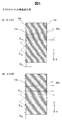
- the relatively small range value of theta 0 is 0 to 10 degrees, by the pitch P 1 of the third texture 15 substantially equal the pitch P 2 of the first Kusucha 16, the moire pattern between each occurrence This is easy to use and can be used effectively. Further, when the line-of-sight position is changed with respect to the light guide 11, the moire pattern moves. As a result, a vehicular lamp that urges surrounding vehicles and pedestrians to call attention can be realized.
- a relatively large value of 10 to 45 degrees may be selected as the value of ⁇ 0 .
- the height D 2 of the protruding portion of the first texture 16 is a 0.03 ⁇ 0.1 mm, gradually increased toward the end portion from the introduction the optical unit 12. With this configuration, the light emission intensity at the propagation position of the light emitting unit 13 is made uniform.
- the angle ⁇ 3 is preferably 20 to 45 degrees, and ⁇ 4 is preferably 45 to 70 degrees. From the combination of these angles ⁇ 1 , ⁇ 2 , ⁇ 3 , and ⁇ 4 , light is emitted from the light emitting surface 13 a of the light emitting unit 13 of the light guide 11 in a direction substantially perpendicular to the surface.
- the height D 3 of the protrusion of the second texture 17 is substantially constant in the light guide, and a relationship of D 3 > D 2 is desirable. But the height D 3 may be periodically varied within a certain range. By periodically varying the depth, the direction of light incident from the outside of the light guide and totally reflected by the second texture 17 can be dispersed within a certain range. By adopting this configuration, when direct sunlight is incident on the light guide, the reflection direction can be dispersed to some extent, and an antiglare effect can be expected. Further, the second texture 17 may be made to meander somewhat rather than having a linear shape. With this configuration, the same antiglare effect as described above can be expected.
- the ratio of the area of the protrusion and the flat part in the second texture 17 is larger. From this viewpoint, the height D 3 of the protrusions of the second texture 17 and the pitch P 3 thereof are determined.
- FIG. 5 is a diagram for explaining the angle of the protrusions of the second texture 17 and the effect thereof.
- the angles ⁇ 5a and ⁇ 6a of the protrusions of the texture 17a are set to approximately 45 degrees.
- a light guide that reflects external light with high reflectivity is realized. it can.
- angles ⁇ 5b and ⁇ 6b of the protrusions of the texture 17b are each set to a value greater than 45 degrees, for example, approximately 50 degrees.
- the light 90b incident from above the outside is totally reflected substantially in the horizontal direction by the texture 17b of the facing surface 13b. Therefore, it is possible to realize a light guide body that reflects external light, particularly light from a relatively bright sky, in the horizontal direction with high reflectivity.
- the configuration (B) is effective as a reflector for recognizing surrounding vehicles and pedestrians in the daytime. Even if the angle of the texture 17 is set to less than 45 degrees, it is possible to reflect the light incident on the opposite surface of the texture in the light from the sky in the horizontal direction. Since the prospective angle becomes small with respect to the light from the light, the amount of reflected light decreases. For the above reasons, when the light guide is applied to a vehicular lamp, it is desirable that the texture angle be 45 degrees or more. When the light guide is applied to an indoor lighting fixture, the texture angle may be 45 degrees or less because it is not necessary to reflect light from the sky effectively.
- a part of the facing surface side 13b of the light emitting unit 13 is configured to totally reflect not only the light emitted from the solid light source 80 but also the light incident from the outside.
- a glittering light guide can be realized even when is turned off.
- the second texture 17 is formed substantially parallel to the direction (X direction) in which the light from the solid light source 80 propagates, the second texture 17 has little diffraction effect on the light from the light source 80. Therefore, the light from the light source 80 is selectively diffracted by the third and first textures 15 and 16.
- the textures 15 and 16 are configured so that the shape gradually increases from the light source 80 toward the propagation direction (X direction). That is, since the intensity of light propagating through the light emitting unit 13 of the light guide gradually decreases, the structure is configured to correct the diffraction effect, so that the light from the light source 80 is emitted substantially uniformly within the light emitting unit 13. It has the characteristic to make it.
- this period is longer than 0.1 mm and shorter than 10 mm.
- the period is shorter than 0.1 mm, the change in the groove shape becomes large, the diffraction effect on the light from the light source 80 becomes strong, the amount of light leaking from the light guide increases, and the light guide characteristics deteriorate.
- the period is longer than 10 mm, when direct sunlight is incident on the light guide, the height or depth of the second texture 17 changes or meanders to disperse the reflection direction to some extent. The width becomes too large and difficult to realize.
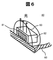
- FIG. 6 is a perspective view showing the configuration of the solid light source 80.
- an LED chip 81 that is a light emitting element is mounted on the substrate 60.
- a resin cap 83 for improving the light emission distribution characteristics of the LED light source may be formed outside the resin cap 83.
- the amount of light emitted from the LED chip 81 in the vertical direction with respect to the chip can be increased, and an effective brighter light source can be realized.
- a phosphor layer 82 that absorbs light from the LED chip 81 and emits fluorescence may be formed outside the LED chip 81 for the purpose of changing the emission spectrum characteristics of the solid light source 80 as necessary.
- the light source device of the first embodiment not only the light emitted from the solid-state light source but also the light incident from the outside is totally reflected. It can be applied to lamps that can be recognized by other vehicles and pedestrians, and highly illuminating devices used in vehicles and indoors.
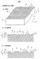
- FIG. 7 is a diagram showing other shapes of the first texture 26 and the second texture 27 formed on the facing surface side 23b of the light emitting unit 23 as a second embodiment of the light source device according to the present invention.
- (A) is a perspective view
- (B) and (C) are X-direction and Y-direction cross-sectional views, respectively.
- a third texture 25 (not shown) formed on the light emitting side 23a of the light emitting unit 23 is the same as the third texture 15 of the first embodiment, and is guided to the light source device 20 of the present embodiment.
- the overall configuration of the light body 21 is the same as that of the light source device 10 and the light guide 11 of the first embodiment.
- the direction of the groove of the third texture 25 is inclined by the angle ⁇ 0 from the Y direction in the same manner as the third texture 15 of the first embodiment, and therefore the third texture 25 is also formed in this embodiment.
- the first texture 26 are disposed with an angle of ⁇ 0 relative to each other. By appropriately selecting the value of the angle ⁇ 0 , a moire pattern is generated between the third texture 25 and the first texture 26 and can be used effectively.
- FIG. 8 is a diagram for explaining the groove angle of the second texture 27 and its effect.
- the groove angles ⁇ 5a and ⁇ 6a of the texture 27a are set to approximately 45 degrees.
- the light 90a incident from the output side 23a from the outside is totally reflected in the same direction as the incident direction by the texture 27a of the opposing surface 23b, a light guide that reflects external light with high reflectivity is realized. it can.
- the groove angles ⁇ 5b and ⁇ 6b of the texture 27b are each set to a value larger than 45 degrees, for example, approximately 50 degrees.
- the light 90b incident from above the outside is totally reflected substantially in the horizontal direction by the texture 27b of the facing surface 23b. Therefore, it is possible to realize a light guide body that reflects external light, particularly light from a relatively bright sky, in the horizontal direction with high reflectivity.
- a part of the facing surface side 23b of the light emitting unit 23 has a structure that totally reflects not only the light emitted from the solid light source 80 but also the light incident from the outside.
- a glittering light guide can be realized even when is turned off.
- FIG. 9 is a sectional view showing the third embodiment of the light source device according to the present invention.
- the light source device 30 propagates the light generated from the two solid light sources 80a and 80b arranged at both ends of the light guide 31 to the light guide 31 and emits the light from the light emitting unit 33 to the outside (upward in the drawing). is there.
- the light emitting side of the light emitting portion 33 is indicated by 33a, and the opposite surface is indicated by 33b.
- the two solid light sources 80a and 80b are mounted on the substrates 70a and 70b, respectively, and are fixed to the support 71 together with the light guide 31 by fixtures 73a and 73b and screws 75a and 75b.
- a reflective film 72 is formed on the surface of the support 71 facing the light emitting portion 33.
- the reflective film 72 may be formed on the facing surface 33 b of the light emitting unit 33.
- FIG. 10A and 10B are perspective views of the light guide body 31 constituting the light source device 30.
- FIG. 10A is a view seen from the light emitting side 33a
- FIG. 10B is a view seen from the facing surface side 33b.
- the light guide 31 made of a transparent material has introduction light portions 32a and 32b for introducing light from the solid light sources 80a and 80b at both ends, and a light emitting portion 33 for emitting light to the outside at the center.
- the light emitting section 33 is a rod having a square cross section, thereby realizing a light source that emits light in a linear shape.
- the introduction light portions 32a and 32b are formed with substantially frustoconical concave grooves as light receiving portions 34a and 34b for fitting the fixed light sources 80a and 80b.
- a third texture 35 having a pitch P 0 period is formed on the light emitting side 33 a of the light emitting unit 33, and a first texture 36 having a pitch P 2 period is formed on the facing surface 33 b of the light emitting unit 33, forming a second texture 37 of the period of the pitch P 3 substantially perpendicular thereto.
- the shapes of these textures 35, 36, and 37 are the same as those in the first and second embodiments. However, since light enters from the two solid light sources 80a and 80b arranged at both ends of the light guide 31, the third texture
- the shapes (angles) of the texture 35 and the first texture 36 are approximately symmetrical in the X direction (in FIGS. 3, 4, and 7, ⁇ 1 ⁇ 2 , ⁇ 3 ⁇ 4 ).
- FIG. 11 is a diagram showing other shapes of the first texture 46 and the second texture 47 formed on the facing surface side 43b of the light emitting unit 43 as a fourth embodiment of the light source device according to the present invention.
- a frustoconical pattern is formed two-dimensionally as the first texture 46, and a groove is formed in the X direction as the second texture 47.
- the first texture 46 is not limited to the prism shape as long as it has a shape that intersects the light propagating through the light emitting unit 43 in the X direction.
- the shape may be a dome shape or the like.
- the light source devices of Examples 1 to 4 described above can be provided with a vehicle lamp having excellent visibility by being attached to at least one of the front, side, rear and interior of the vehicle.
- the light source device is mainly used as a vehicle lamp, but the present invention is not limited to this. That is, the third texture formed in a direction substantially parallel to the light propagating through the light guide has a function of totally reflecting the light inside the light guide, so that a metal film such as aluminum is formed on the surface of the light guide. Therefore, it is possible to realize a lighting device that exhibits metallic luster and is low in cost and highly attractive.
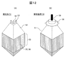
- FIG. 12 is a perspective view illustrating a configuration of a lighting apparatus according to the fifth embodiment.
- (A) shows the part of the light guide 51
- (B) shows an example applied to the illumination device 50.
- the light guide 51 includes an introduction light portion 52 and a light emission portion 53.
- the introduction light part 52 has a concave light receiving part 54 and a connecting part 57 into which a solid light source (not shown) is fitted.
- the light guide 51 is formed of a transparent resin such as acrylic, and the metal connecting portion is integrally formed with the light guide 51 by insert molding.
- a first texture 55 having a periodic shape is formed in a direction (a substantially horizontal direction in the drawing) in which a part of the light propagating through the light guide 51 is diffracted to the outside.
- a second texture 56 is formed so as to be superimposed in a direction substantially parallel to the light propagating through the light guide 51 (substantially perpendicular to the drawing).
- the shapes of the textures 55 and 56 the shapes shown in FIGS. 4, 7, and 11 can be applied.
- the inclination angle of the second texture 56 does not need to be 45 degrees or more, and a critical angle of 43 degrees at which total reflection of light occurs. It only needs to be around. By adopting this configuration, even when a structure in which the second texture 56 is formed in the direction of the side surface 4 is adopted, it is easy to remove the mold at the time of molding, and productivity is improved.
- the light guide 51 is connected to a cover 58 by a connector 57, and a power cable 59 is connected to the upper portion of the cover 58.
- the lighting fixture 50 having the above configuration is used by being attached to a ceiling surface, a wall surface, or outdoors.
- the second texture 56 is formed so as to overlap the four side surfaces of the light guide 51 and the four sides of the quadrangular pyramid. With this configuration, the light inside the light guide 51 is totally reflected many times by the second texture 56, the light is confined to some extent, and a part is diffracted by the third texture 56 and emitted to the outside. A brilliant lighting fixture can be realized.
Landscapes
- Engineering & Computer Science (AREA)
- General Engineering & Computer Science (AREA)
- Physics & Mathematics (AREA)
- Microelectronics & Electronic Packaging (AREA)
- Optics & Photonics (AREA)
- Planar Illumination Modules (AREA)
Abstract
Dispositif source de lumière (10) pourvu d'une source de lumière (80) à l'état solide et d'un guide de lumière (11) qui propage et émet à l'extérieur de la lumière émise par la source lumineuse à l'état solide. Le guide de lumière (11) comprend au moins une première surface (13a) qui émet de la lumière et une seconde surface (13b) qui est opposée et approximativement parallèle à la première surface. Sur la seconde surface (13b), une première texture (16) qui diffracte la lumière se propageant dans le guide de lumière, et une seconde texture (17) qui est approximativement perpendiculaire à la première texture et qui réfléchit totalement au moins une partie de la lumière se propageant dans le guide de lumière, sont formées de manière à être superposées l'une à l'autre. Une troisième texture (15), qui diffracte la lumière se propageant dans le guide de lumière, peut éventuellement être formée sur la première surface (13a).
Priority Applications (1)
| Application Number | Priority Date | Filing Date | Title |
|---|---|---|---|
| PCT/JP2015/052040 WO2016120974A1 (fr) | 2015-01-26 | 2015-01-26 | Dispositif source de lumière, et équipement d'éclairage et lampe d'automobile utilisant celui-ci |
Applications Claiming Priority (1)
| Application Number | Priority Date | Filing Date | Title |
|---|---|---|---|
| PCT/JP2015/052040 WO2016120974A1 (fr) | 2015-01-26 | 2015-01-26 | Dispositif source de lumière, et équipement d'éclairage et lampe d'automobile utilisant celui-ci |
Publications (1)
| Publication Number | Publication Date |
|---|---|
| WO2016120974A1 true WO2016120974A1 (fr) | 2016-08-04 |
Family
ID=56542633
Family Applications (1)
| Application Number | Title | Priority Date | Filing Date |
|---|---|---|---|
| PCT/JP2015/052040 Ceased WO2016120974A1 (fr) | 2015-01-26 | 2015-01-26 | Dispositif source de lumière, et équipement d'éclairage et lampe d'automobile utilisant celui-ci |
Country Status (1)
| Country | Link |
|---|---|
| WO (1) | WO2016120974A1 (fr) |
Cited By (2)
| Publication number | Priority date | Publication date | Assignee | Title |
|---|---|---|---|---|
| CN111288412A (zh) * | 2018-12-07 | 2020-06-16 | 常州星宇车灯股份有限公司 | 一种具有循序变化的表面纹理结构的汽车配件 |
| CN114353009A (zh) * | 2022-01-11 | 2022-04-15 | 马瑞利汽车零部件(芜湖)有限公司 | 空间造型叠加车灯光学系统 |
Citations (3)
| Publication number | Priority date | Publication date | Assignee | Title |
|---|---|---|---|---|
| JP2000305073A (ja) * | 1999-04-22 | 2000-11-02 | Mitsubishi Electric Corp | 液晶表示装置用バックライト |
| JP3164028U (ja) * | 2010-08-30 | 2010-11-11 | 嘉威光電股▲分▼有限公司 | 光学薄膜、及び、光学薄膜を応用したバックライトモジュール |
| JP2011192468A (ja) * | 2010-03-12 | 2011-09-29 | Hitachi Displays Ltd | 照明装置および液晶表示装置 |
-
2015
- 2015-01-26 WO PCT/JP2015/052040 patent/WO2016120974A1/fr not_active Ceased
Patent Citations (3)
| Publication number | Priority date | Publication date | Assignee | Title |
|---|---|---|---|---|
| JP2000305073A (ja) * | 1999-04-22 | 2000-11-02 | Mitsubishi Electric Corp | 液晶表示装置用バックライト |
| JP2011192468A (ja) * | 2010-03-12 | 2011-09-29 | Hitachi Displays Ltd | 照明装置および液晶表示装置 |
| JP3164028U (ja) * | 2010-08-30 | 2010-11-11 | 嘉威光電股▲分▼有限公司 | 光学薄膜、及び、光学薄膜を応用したバックライトモジュール |
Cited By (2)
| Publication number | Priority date | Publication date | Assignee | Title |
|---|---|---|---|---|
| CN111288412A (zh) * | 2018-12-07 | 2020-06-16 | 常州星宇车灯股份有限公司 | 一种具有循序变化的表面纹理结构的汽车配件 |
| CN114353009A (zh) * | 2022-01-11 | 2022-04-15 | 马瑞利汽车零部件(芜湖)有限公司 | 空间造型叠加车灯光学系统 |
Similar Documents
| Publication | Publication Date | Title |
|---|---|---|
| JP6224110B2 (ja) | 自動車両の照明および/または合図装置 | |
| KR102224459B1 (ko) | 입체조명장치 및 이를 이용하는 차량조명장치 | |
| US8820964B2 (en) | Linear lighting system | |
| US20220364708A1 (en) | Lighting Arrangements for Targeted Illumination Patterns | |
| CN106030201B (zh) | 光学构件以及使用光学构件的照明装置 | |
| RU2605690C2 (ru) | Светильник | |
| JP2013502685A (ja) | 照明装置及び斯かる照明装置に適したレンズ | |
| JPWO2012063759A1 (ja) | Led照明装置 | |
| JP2014509433A (ja) | 拡散光を発するための発光素子 | |
| CN104748066A (zh) | 光学构件及使用光学构件的照明装置 | |
| WO2016059465A1 (fr) | Conception de luminaire à del linéaire asymétrique pour un éclairage et une couleur uniformes | |
| JP2012182117A (ja) | 管型照明器具、管型照明器具用筐体及び両面内照式看板装置 | |
| JP2009131998A (ja) | 装飾用パネル | |
| US20140293649A1 (en) | Illumination device and automotive lamp | |
| JP6826757B2 (ja) | 乗物用照明装置 | |
| WO2016120974A1 (fr) | Dispositif source de lumière, et équipement d'éclairage et lampe d'automobile utilisant celui-ci | |
| EP2653777A1 (fr) | Dispositif d'éclairage et module d'éclairage indirect par corniches l'utilisant | |
| JP5472193B2 (ja) | 光源ユニットおよび照明装置 | |
| TW201510592A (zh) | 照明裝置 | |
| GB2480758A (en) | Light guide with first and second light output surfaces | |
| US7217010B2 (en) | Reflector with negative focal length | |
| JPWO2017046945A1 (ja) | 光源装置及びそれを利用した照明器具と車両用灯具 | |
| JP5202602B2 (ja) | 透光性部材 | |
| JP2006044330A (ja) | 発光装置 | |
| JP2006012588A (ja) | 光学部品および該光学部品を使用した照明燈 |
Legal Events
| Date | Code | Title | Description |
|---|---|---|---|
| 121 | Ep: the epo has been informed by wipo that ep was designated in this application |
Ref document number: 15879871 Country of ref document: EP Kind code of ref document: A1 |
|
| NENP | Non-entry into the national phase |
Ref country code: DE |
|
| NENP | Non-entry into the national phase |
Ref country code: JP |
|
| 122 | Ep: pct application non-entry in european phase |
Ref document number: 15879871 Country of ref document: EP Kind code of ref document: A1 |