WO2016120984A1 - Carter de compresseur centrifuge et compresseur centrifuge - Google Patents
Carter de compresseur centrifuge et compresseur centrifuge Download PDFInfo
- Publication number
- WO2016120984A1 WO2016120984A1 PCT/JP2015/052131 JP2015052131W WO2016120984A1 WO 2016120984 A1 WO2016120984 A1 WO 2016120984A1 JP 2015052131 W JP2015052131 W JP 2015052131W WO 2016120984 A1 WO2016120984 A1 WO 2016120984A1
- Authority
- WO
- WIPO (PCT)
- Prior art keywords
- piece
- casing
- volute
- casing body
- centrifugal compressor
- Prior art date
- Legal status (The legal status is an assumption and is not a legal conclusion. Google has not performed a legal analysis and makes no representation as to the accuracy of the status listed.)
- Ceased
Links
Images


Classifications
-
- F—MECHANICAL ENGINEERING; LIGHTING; HEATING; WEAPONS; BLASTING
- F04—POSITIVE - DISPLACEMENT MACHINES FOR LIQUIDS; PUMPS FOR LIQUIDS OR ELASTIC FLUIDS
- F04D—NON-POSITIVE-DISPLACEMENT PUMPS
- F04D29/00—Details, component parts, or accessories
- F04D29/40—Casings; Connections of working fluid
- F04D29/42—Casings; Connections of working fluid for radial or helico-centrifugal pumps
- F04D29/44—Fluid-guiding means, e.g. diffusers
- F04D29/441—Fluid-guiding means, e.g. diffusers especially adapted for elastic fluid pumps
-
- F—MECHANICAL ENGINEERING; LIGHTING; HEATING; WEAPONS; BLASTING
- F04—POSITIVE - DISPLACEMENT MACHINES FOR LIQUIDS; PUMPS FOR LIQUIDS OR ELASTIC FLUIDS
- F04D—NON-POSITIVE-DISPLACEMENT PUMPS
- F04D17/00—Radial-flow pumps, e.g. centrifugal pumps; Helico-centrifugal pumps
- F04D17/08—Centrifugal pumps
- F04D17/10—Centrifugal pumps for compressing or evacuating
- F04D17/12—Multi-stage pumps
-
- F—MECHANICAL ENGINEERING; LIGHTING; HEATING; WEAPONS; BLASTING
- F04—POSITIVE - DISPLACEMENT MACHINES FOR LIQUIDS; PUMPS FOR LIQUIDS OR ELASTIC FLUIDS
- F04D—NON-POSITIVE-DISPLACEMENT PUMPS
- F04D17/00—Radial-flow pumps, e.g. centrifugal pumps; Helico-centrifugal pumps
- F04D17/08—Centrifugal pumps
- F04D17/10—Centrifugal pumps for compressing or evacuating
- F04D17/12—Multi-stage pumps
- F04D17/122—Multi-stage pumps the individual rotor discs being, one for each stage, on a common shaft and axially spaced, e.g. conventional centrifugal multi- stage compressors
- F04D17/125—Multi-stage pumps the individual rotor discs being, one for each stage, on a common shaft and axially spaced, e.g. conventional centrifugal multi- stage compressors the casing being vertically split
-
- F—MECHANICAL ENGINEERING; LIGHTING; HEATING; WEAPONS; BLASTING
- F04—POSITIVE - DISPLACEMENT MACHINES FOR LIQUIDS; PUMPS FOR LIQUIDS OR ELASTIC FLUIDS
- F04D—NON-POSITIVE-DISPLACEMENT PUMPS
- F04D29/00—Details, component parts, or accessories
- F04D29/40—Casings; Connections of working fluid
- F04D29/42—Casings; Connections of working fluid for radial or helico-centrifugal pumps
- F04D29/4206—Casings; Connections of working fluid for radial or helico-centrifugal pumps especially adapted for elastic fluid pumps
- F04D29/422—Discharge tongues
-
- F—MECHANICAL ENGINEERING; LIGHTING; HEATING; WEAPONS; BLASTING
- F04—POSITIVE - DISPLACEMENT MACHINES FOR LIQUIDS; PUMPS FOR LIQUIDS OR ELASTIC FLUIDS
- F04D—NON-POSITIVE-DISPLACEMENT PUMPS
- F04D29/00—Details, component parts, or accessories
- F04D29/60—Mounting; Assembling; Disassembling
- F04D29/62—Mounting; Assembling; Disassembling of radial or helico-centrifugal pumps
- F04D29/624—Mounting; Assembling; Disassembling of radial or helico-centrifugal pumps especially adapted for elastic fluid pumps
-
- F—MECHANICAL ENGINEERING; LIGHTING; HEATING; WEAPONS; BLASTING
- F04—POSITIVE - DISPLACEMENT MACHINES FOR LIQUIDS; PUMPS FOR LIQUIDS OR ELASTIC FLUIDS
- F04D—NON-POSITIVE-DISPLACEMENT PUMPS
- F04D29/00—Details, component parts, or accessories
- F04D29/40—Casings; Connections of working fluid
- F04D29/42—Casings; Connections of working fluid for radial or helico-centrifugal pumps
- F04D29/4206—Casings; Connections of working fluid for radial or helico-centrifugal pumps especially adapted for elastic fluid pumps
- F04D29/4226—Fan casings
-
- F—MECHANICAL ENGINEERING; LIGHTING; HEATING; WEAPONS; BLASTING
- F04—POSITIVE - DISPLACEMENT MACHINES FOR LIQUIDS; PUMPS FOR LIQUIDS OR ELASTIC FLUIDS
- F04D—NON-POSITIVE-DISPLACEMENT PUMPS
- F04D29/00—Details, component parts, or accessories
- F04D29/40—Casings; Connections of working fluid
- F04D29/42—Casings; Connections of working fluid for radial or helico-centrifugal pumps
- F04D29/426—Casings; Connections of working fluid for radial or helico-centrifugal pumps especially adapted for liquid pumps
- F04D29/428—Discharge tongues
Definitions
- the present invention relates to a casing in a centrifugal compressor and a centrifugal compressor including the casing.
- centrifugal compressors are used in various plants to compress process gas.
- the process gas sucked into the casing from the suction port is compressed in the flow path of the impeller as the impeller rotates together with the rotating shaft, and discharged from the discharge port to the outside of the casing.
- a discharge volute communicating with the discharge port is formed in the casing of the centrifugal compressor. This discharge volute keeps the flow rate of the process gas constant and reduces pressure loss.
- This discharge volute is generally formed by welding a volute piece separate from the casing into an annular groove formed on the inner surface of the casing (see Patent Document 1).
- the present invention provides a casing of a centrifugal compressor that can easily form a discharge volute regardless of the material, and a centrifugal compressor including the casing.
- the casing of the centrifugal compressor according to the first aspect of the present invention supports a rotating shaft and an impeller fixed to the rotating shaft and rotating together with the rotating shaft so as to be rotatable about the axis of the rotating shaft. And an inlet suction channel having an annular shape around the axis for introducing fluid into the channel of the impeller, and a discharge channel having an annular shape centered on the axis for discharging the fluid from the channel of the impeller , A casing main body that covers the bundle from the outer peripheral side, and an inner surface of the casing main body in the discharge flow path, and in the circumferential direction of the rotating shaft, on the downstream side in the fluid flow direction And a fastening member for fixing the volute piece to the casing main body, the radial thickness of the rotary shaft gradually decreasing toward the outlet of the discharge flow path. It is equipped with a.
- the discharge volute can be formed in the casing by fastening and fixing the volute piece to the discharge flow path in the casing body with a fastening member. Therefore, unlike the case where the volute piece is welded and fixed to the casing body, it is possible to avoid the occurrence of cracks in the welded portion of the casing body and the volute piece when the volute piece is fixed. Moreover, since a volute piece is only fixed with a fastening member without using welding, a high technique is not required when fixing the volute piece.
- the fastening member in the first aspect penetrates the casing body from the outside in the radial direction and is fixed to the volute piece.
- the volute piece may be fixed to the casing body, and the casing body may further include a closing member that is provided on the casing body from the outside in the radial direction and that closes a through hole that penetrates the casing body.
- the fastening member is provided from the outside of the casing main body in this way, the volute piece is fixed to the casing main body, so that the fixing operation of the volute piece is easy and the work man-hours can be reduced. Furthermore, by providing the closing member, it is possible to suppress the fluid in the discharge flow channel from leaking out of the casing body through the through hole.
- the fastening member in the first aspect penetrates the volute piece from the inside in the radial direction and is fixed to the casing body.
- the volute piece may be fixed to the casing body.
- the volute piece according to any one of the first to third aspects is a first piece portion disposed on the downstream side in the fluid flow direction. And a second piece portion that is formed separately from the first piece portion and that is disposed upstream of the first piece portion in the fluid flow direction.
- the volute piece is divided into the first piece portion and the second piece portion, so that the volute piece can be easily fixed to the casing body. Furthermore, when the pressure is applied to the casing body during the operation of the centrifugal compressor and the casing body is deformed, the first piece portion and the volute piece are compared with the case where the volute pieces are integrally formed without being divided. If a gap is formed in the divided part with the second piece part, it becomes possible to absorb the deformation of the casing body in this divided part. Therefore, it is possible to suppress the cracking of the volute piece when the casing body is deformed.
- any one of the first piece part and the second piece part in the fourth aspect is directed toward the other side in the circumferential direction.
- the other has an engaging portion that is supported by the protrusion from the inside in the radial direction, and the fastening member is the only one. May be provided.
- the first piece part and the second piece It may be difficult to fasten and fix one of the first piece and the second piece to the casing due to lack of work space or interference with the components of the casing. Even in such a case, if only one of the first piece part and the second piece part is fastened and fixed to the casing body by supporting the engaging part by the protrusion, the first piece part and the second piece It becomes possible to fix the other of the parts to the casing body. That is, when one of the first piece portion and the second piece portion is fixed to the casing body with the fastening member, the engaging portion supports the protruding portion against the casing body, and the fastening member supports the first piece portion. The other of the one piece and the second piece can also be fixed to the casing body.
- the first piece part in the fifth aspect is the one side, the protrusion is provided, and the second piece part is the On the other hand, you may have the said engaging part.
- the fastening member can be provided at a position separated from the outlet of the discharge flow path. For this reason, interference of the fastening member to the discharge port or the like connected to the discharge flow path can be avoided, and the volute piece can be easily fixed to the casing body.
- the material of the casing body in any one of the first to fifth aspects is a high yield strength of 500 [N / mm 2 ] or more. It may be a strength material.
- a centrifugal compressor according to an eighth aspect of the present invention is supported by the casing according to any one of the first to seventh aspects, and the casing so as to be rotatable with respect to the casing.
- the discharge volute can be formed in the casing by fastening and fixing the volute piece to the discharge flow path in the casing body. Therefore, unlike the case where the volute piece is fixed to the casing body by welding, when the volute piece is fixed, the occurrence of cracks in the welded portion of the casing main body or the volute piece due to heat can be avoided, and when the discharge volute is formed High technology is not required.
- the volute piece can be easily fixed to the casing body to form a discharge volute.
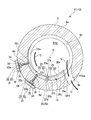
- FIG. 2 is a view showing a discharge flow path and a volute piece of the centrifugal compressor in the first embodiment of the present invention, and is a cross-sectional view taken along line AA of FIG.
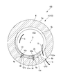
- FIG. 4 is a view showing a discharge flow path and a volute piece of a centrifugal compressor in a modification of the first embodiment of the present invention, and is a cross-sectional view corresponding to the AA cross section of FIG.
- FIG. 4 is a view showing a discharge flow path and a volute piece of a centrifugal compressor according to a second embodiment of the present invention, and is a cross-sectional view corresponding to the AA cross section of FIG.
- each of a pair of three-stage impeller groups 4 that rotate about an axis O includes one side and the other side in the direction of the axis O.
- a multistage centrifugal compressor arranged symmetrically will be described.
- the centrifugal compressor 1 includes a rotating shaft 2 that rotates about an axis O, a plurality of impellers 3 fixed to the rotating shaft 2, and a casing 5 that rotatably supports the rotating shaft 2 and the impeller 3. .
- the rotating shaft 2 has a cylindrical shape with the axis O as the center.
- a plurality (six in this embodiment) of the impellers 3 are arranged apart from each other in the direction of the axis O.
- Each impeller 3 has a substantially disk shape, and can be rotated around the axis O together with the rotary shaft 2 by being fitted into the rotary shaft 2.
- Each impeller 3 is formed with a flow path FC through which a process gas G (fluid) can flow.
- Three impellers 3 arranged on one side in the direction of the axis O are arranged such that the inlet of the flow path FC faces one side in the direction of the axis O, and one impeller group 4 (hereinafter referred to as first impeller group 4A).
- the three-stage impeller 3 arranged on the other side in the direction of the axis O (on the right side in FIG. 1) is arranged such that the inlet of the flow path FC faces the other side in the direction of the axis O.
- Group 4 (hereinafter referred to as second impeller group 4B) is configured.
- the casing 5 includes a bundle 10 having a plurality of diaphragms 11 having a disk shape centered on the axis O, a casing body 6 that covers the bundle 10 from the outer peripheral side, a volute piece 19 that is provided separately from the casing body 6, A fastening member 30 for fixing the volute piece 19 to the casing body 6 and a closing member 31 provided so as to cover the fastening member 30 are provided.
- the bundle 10 is formed by connecting a plurality of diaphragms 11 and a head 12 in the direction of the axis O with bolts (not shown). That is, the bundle 10 has a structure divided into a plurality of sections in a cross section orthogonal to the axis O.
- the head 12 is a member that is provided in a pair so as to sandwich the plurality of diaphragms 11 at both ends of the axis O from the direction of the axis O, and has a disk shape centered on the axis O.
- Each diaphragm 11 is a horizontal plane including the axis O, and has a structure that is divided into two vertically.
- the diaphragms 11 at one end and the other end in the direction of the axis O are suction diaphragms 11A.
- the suction diaphragm 11 ⁇ / b> A is formed with a suction flow path FC ⁇ b> 1 that has an annular shape about the axis O and that can introduce the process gas G into the flow path FC of the impeller 3.
- the suction flow path FC1 is formed with a suction flow path opening OP1 that opens radially outward at a part of the suction diaphragm 11A in the circumferential direction (upper part in the present embodiment).
- the diaphragm 11 covering the first stage (first stage) impeller 3 (3A) in the first impeller group 4A and the second impeller group 4B is a first intermediate diaphragm 11B.
- the first intermediate diaphragm 11B has a return flow path FC3 that communicates the outlet of the flow path FC of the first stage impeller 3 (3A) and the inlet of the flow path FC of the intermediate stage (second stage) impeller 3 (3B). Is formed.
- the diaphragm 11 covering the middle stage (second stage) impeller 3 (3B) in the first impeller group 4A and the second impeller group 4B is a second intermediate diaphragm 11C.
- the second intermediate diaphragm 11C has a return flow path FC4 communicating with the outlet of the flow path FC of the intermediate stage impeller 3 (3B) and the inlet of the flow path FC of the final stage (third stage) impeller 3 (3C). Is formed.
- the second intermediate diaphragm 11C has an annular shape centering on the axis O, and a part of the discharge flow path FC2 that allows the process gas G to be discharged from the flow path FC of the impeller 3 is formed.
- the diaphragm 11 covering the final stage (third stage) impeller 3 (3C) in the first impeller group 4A and the second impeller group 4B is a discharge diaphragm 11D.
- the discharge diaphragm 11D has an annular shape centered on the axis O, and the remaining part of the discharge flow path FC2 that allows the process gas G to be discharged from the flow path FC of the impeller 3 is formed.
- the discharge flow path FC2 is formed by the discharge diaphragm 11D and the second intermediate diaphragm 11C.
- a discharge flow path opening OP2 (exit) that opens radially outward at a part of the circumferential direction (upper part in the present embodiment) of the second intermediate diaphragm 11C and the discharge diaphragm 11D is formed.
- the diaphragm 11 disposed at a position between the first impeller group 4A and the second impeller group 4B is a final interstage diaphragm 11E.
- the final interstage diaphragm 11E is provided with a sealing device 15 that seals the flow of the process gas G between the first impeller group 4A and the second impeller group 4B on the outer peripheral side of the rotating shaft 2. .
- the casing body 6 is formed of, for example, a high-strength material having a yield strength of 500 [N / mm 2 ] or more. Examples of such a high strength material include SFCM880.
- the casing body 6 has a cylindrical shape, covers the bundle 10 from the outer peripheral side, and fixes the bundle 10.
- the casing body 6 is formed with a pair of suction ports 6a that extend in the radial direction and open outward, and communicate with the suction flow path opening OP1.
- the casing body 6 extends radially and opens outward.
- a pair of discharge ports 6b communicating with the discharge flow path opening OP2 is formed.
- the volute piece 19 is provided on the inner surface 6c of the casing body 6 forming the discharge flow path FC2 in the discharge flow path FC2 formed across the second intermediate diaphragm 11C and the discharge diaphragm 11D of the bundle 10. .
- the volute piece 19 is provided for about a half circumference in the circumferential direction of the rotating shaft 2, and as it goes toward the discharge flow path opening OP ⁇ b> 2 that is downstream in the flow direction of the process gas G in the circumferential direction.
- the volute piece 19 is separate from the first piece portion 21 and the first piece portion 21 that are disposed on the downstream side in the flow direction of the process gas G, and more than the first piece portion 21.
- a second piece 25 arranged on the upstream side in the flow direction of the process gas G. That is, the second piece 25 is disposed on the side close to the discharge flow path opening OP2, and the first piece 21 is disposed on the side away from the discharge flow path opening OP2.
- the first piece portion 21 includes a body portion 22 that curves in the circumferential direction along the inner surface 6c of the casing body 6 and a protrusion 23 that projects in the circumferential direction from the upstream side of the body portion 22 toward the second piece portion 25. And have.
- the main body 22 has a surface in which an inner surface 22a facing radially inward is curved along the circumferential direction.
- the main body portion 22 is formed with a bolt hole 22c extending from the outer surface 22b facing the inner surface 6c of the casing main body 6 toward the radially outer side to the radially middle position toward the radially inner side.
- a female screw is formed in the bolt hole 22c.
- the bolt holes 22c are formed at two locations apart in the circumferential direction.
- the downstream end of the main body 22 has a reduced radial thickness.
- the protrusion 23 protrudes from the radially inner end of the surface facing the upstream side of the main body 22 and is formed integrally with the main body 22.
- the inner surface 23a facing the radially inner side of the protrusion 23 is flush with the inner surface 22a of the main body 22 and is a surface that curves along the circumferential direction.
- the second piece 25 includes a main body 26 that curves in the circumferential direction along the inner surface 6 c of the casing main body 6, and an engagement portion that protrudes in the circumferential direction from the downstream side of the main body 26 toward the first piece 21. 27.
- the main body part 26 is a surface in which an inner surface 26a facing radially inward is curved along the circumferential direction.
- the inner surface 26 a is flush with the inner surface 22 a of the main body portion 22 and the inner surface 23 a of the protrusion 23 in the first piece portion 21.
- the end surface 26c facing the upstream side of the main body 26 is smoothly connected to the inner surface FC2a of the discharge flow path opening OP2 without a step.
- the engaging portion 27 protrudes from the radially outer end of the surface facing the downstream side of the main body 26 and is formed integrally with the main body 26.
- the outer surface 27 b facing the radially outer side of the engaging portion 27 is continuous with the outer surface 26 b facing the radially outer side of the main body portion 26 and the outer surface 22 b of the main body portion 22 of the first piece portion 21.
- the inner surface 27 a facing the radially inner side of the engaging portion 27 is in contact with the outer surface 23 b facing the radially outer side of the protrusion 23 of the first piece portion 21. Accordingly, the protrusion 23 of the first piece 21 is engaged with the engaging portion 27, and the engaging portion 27 is supported by the protrusion 23 from the inside in the radial direction.
- Bolts 28 are inserted into through-holes 23c that penetrate the projections 23 in the radial direction, and are screwed into bolt holes 27c formed in the engagement portions 27 so as to extend in the radial direction.
- the engaging portion 27 is coupled.
- the fastening member 30 is, for example, a bolt or the like, and is provided on the casing body 6 from the outside in the radial direction.
- the volute piece 19 is fixed to the casing body 6 to form a discharge volute in the casing 5.
- the casing body 6 is formed with through holes 6d penetrating the casing body 6 in the radial direction at positions corresponding to the respective bolt holes 22c formed in the first piece portion 21.
- the fastening member 30 is inserted into the through hole 6d and is screwed into the bolt hole 22c of the first piece 21.
- the bolt head 30a of the bolt that is the fastening member 30 enters the through hole 6d formed in the casing body 6 and does not protrude radially outward from the outer surface 6e of the casing body 6.
- the closing member 31 has a blind flange 32 having a larger diameter than the bolt head 30a, and a metal packing 33 sandwiched between the blind flange 32 and the through hole 6d.
- the closing member 31 closes the through hole 6d from the outside in the radial direction.
- the blind flange 32 is a region including the opening of the through-hole 6 d and is disposed in a recessed portion 6 f that is recessed from the outer surface 6 e of the casing body 6, and is fixed to the casing body 6 by bolts 34.
- the thickness dimension in the radial direction of the blind flange 32 is larger than the depth dimension in the radial direction of the recess 6f. Therefore, the blind flange 32 is provided in a state of projecting radially outward from the recess 6f.
- the discharge volute can be formed in the casing 5 by fastening and fixing the volute piece 19 to the casing body 6 by the fastening member 30 in the discharge flow path FC2 in the bundle 10. Therefore, unlike the case where the volute piece 19 is fixed to the casing body 6 by welding, it is possible to prevent the welded portion of the casing body 6 or the volute piece 19 from being cracked when the volute piece 19 is fixed.
- the volute piece 19 when the above-described high-strength material is used for the casing body 6, a very high welding technique is required when the volute piece 19 is fixed to the casing body 6 by welding.
- the volute piece 19 can be fixed to the casing body 6 without using welding. Therefore, a discharge volute can be easily formed in the casing 5 regardless of the material of the casing body 6.
- the fastening member 30 is provided from the outside of the casing body 6 and the volute piece 19 is fixed to the casing body 6, the fixing operation of the volute piece 19 is easy, and the number of work steps can be reduced.
- the process gas G in the discharge flow path FC2 is passed through the through hole 6d. Leakage to the outside of the main body 6 can be suppressed.
- volute piece 19 is divided into the first piece portion 21 and the second piece portion 25, the volute piece 19 can be easily fixed to the casing body 6.
- the centrifugal compressor 1 pressure may act on the casing body 6, and the casing body 6 may be deformed so as to expand its diameter, for example. In this case, if the deformation amount of the casing body 6 and the deformation amount of the volute piece 19 are different, the deformation of the volute piece 19 may not be able to follow the deformation of the casing body 6.
- the volute piece 19 is divided into the first piece portion 21 and the second piece portion 25 so that a gap is formed in the divided portion. Then, it becomes possible to absorb the deformation of the casing body 6 at this divided portion. Therefore, cracking of the volute piece 19 when the casing body 6 is deformed can be suppressed.
- volute piece 19 may be fixed to the casing body 6 with a gap provided between the first piece portion 21 and the second piece portion 25.
- first piece portion 21 and the second piece portion 25 it is difficult to fasten and fix one of the first piece portion 21 and the second piece portion 25 to the casing body 6 because there is no work space or the components of the casing body 6 interfere. There is a case. Even in such a case, only the first piece portion 21 is supported on the casing body 6 by supporting the engaging portion 27 of the second piece portion 25 from the radially inner side by the protrusion 23 of the first piece portion 21. The second piece 25 can be fixed to the casing body 6 by fastening and fixing to the casing body 6.
- the protrusion 23 supports the engaging portion 27 so as to press it toward the casing body 6, and the second piece 25 is supported by the casing body 6. Can be fixed to.
- the first piece portion 21 is disposed at a position separated from the discharge passage opening OP2 of the discharge passage FC2, when the fastening member 30 is provided on the first piece portion 21, the first piece portion 21 is disposed in the discharge passage FC2. Interference of the fastening member 30 to the discharge port 6b or the like to be connected can be avoided, and the volute piece 19 can be easily fixed to the casing body 6.
- the shape of the protrusion 23 and the engagement portion 27 may be such that they can be engaged and the protrusion 27 can support the engagement portion 27 from the inside in the radial direction.
- the protrusion 23 may have a convex shape when viewed from the direction of the axis O
- the engaging portion 27 may have a concave shape when viewed from the direction of the axis O, and these may be fitted.
- the volute piece 19 ⁇ / b> A does not have a portion corresponding to the protrusion 23, and the second piece portion 25 ⁇ / b> A is connected to the engagement portion 27. It does not have to have a corresponding part. That is, the volute piece 19A is divided into a first piece portion 21A and a second piece portion 25A by a dividing surface 19Aa extending in the radial direction.
- the first piece portion 21 ⁇ / b> A and the second piece portion 25 ⁇ / b> A are each fixed to the casing body 6 with a fastening member 30.
- volute pieces 19, 19A do not necessarily have to be divided into two, and may be further divided into a plurality of pieces.
- the first piece 121 of the volute piece 109 is formed with a through-hole 121a penetrating in the radial direction.
- the through-holes 121a are formed at two locations apart from each other in the circumferential direction.
- Bolt holes 6g are formed in the casing main body 6 so as to extend from the inner surface 6c toward the radially inner position toward the radially inner side.
- a female screw is formed in the bolt hole 6g. Further, the positions of these bolt holes 6 g correspond to the positions of the through holes 121 a of the first piece 121.
- the fastening member 30 is inserted through the through hole 121a of the first piece 121 so as to penetrate the volute piece 109 from the inside in the radial direction, and is screwed and fixed to the bolt hole 6g of the casing body 6.
- the volute piece 109 is fixed to the casing body 6.
- the fastening member 30 can be prevented from penetrating the casing body 6 by providing the fastening member 30 from the inside of the casing body 6. For this reason, the discharge flow path FC2 does not open to the outside of the casing body 6, and a member for closing the opening of the through hole 6d of the casing body 6 as in the closing member 31 of the first embodiment needs to be provided separately. No (see Figure 2).
Landscapes
- Engineering & Computer Science (AREA)
- Mechanical Engineering (AREA)
- General Engineering & Computer Science (AREA)
- Structures Of Non-Positive Displacement Pumps (AREA)
Abstract
Priority Applications (4)
| Application Number | Priority Date | Filing Date | Title |
|---|---|---|---|
| JP2016571535A JP6344872B2 (ja) | 2015-01-27 | 2015-01-27 | 遠心圧縮機のケーシング、及び、遠心圧縮機 |
| PCT/JP2015/052131 WO2016120984A1 (fr) | 2015-01-27 | 2015-01-27 | Carter de compresseur centrifuge et compresseur centrifuge |
| US15/546,221 US10539151B2 (en) | 2015-01-27 | 2015-01-27 | Centrifugal compressor casing and centrifugal compressor |
| EP15879881.9A EP3239534A4 (fr) | 2015-01-27 | 2015-01-27 | Carter de compresseur centrifuge et compresseur centrifuge |
Applications Claiming Priority (1)
| Application Number | Priority Date | Filing Date | Title |
|---|---|---|---|
| PCT/JP2015/052131 WO2016120984A1 (fr) | 2015-01-27 | 2015-01-27 | Carter de compresseur centrifuge et compresseur centrifuge |
Publications (1)
| Publication Number | Publication Date |
|---|---|
| WO2016120984A1 true WO2016120984A1 (fr) | 2016-08-04 |
Family
ID=56542642
Family Applications (1)
| Application Number | Title | Priority Date | Filing Date |
|---|---|---|---|
| PCT/JP2015/052131 Ceased WO2016120984A1 (fr) | 2015-01-27 | 2015-01-27 | Carter de compresseur centrifuge et compresseur centrifuge |
Country Status (4)
| Country | Link |
|---|---|
| US (1) | US10539151B2 (fr) |
| EP (1) | EP3239534A4 (fr) |
| JP (1) | JP6344872B2 (fr) |
| WO (1) | WO2016120984A1 (fr) |
Cited By (3)
| Publication number | Priority date | Publication date | Assignee | Title |
|---|---|---|---|---|
| EP3450765A1 (fr) * | 2017-09-05 | 2019-03-06 | Mitsubishi Heavy Industries Compressor Corporation | Compresseur, ensemble de moitié supérieure du compresseur, moitié supérieure du diaphragme du compresseur et procédé d'assemblage du compresseur |
| JP2019044659A (ja) * | 2017-08-31 | 2019-03-22 | 三菱重工コンプレッサ株式会社 | 遠心圧縮機 |
| WO2025234470A1 (fr) * | 2024-05-10 | 2025-11-13 | 川崎重工業株式会社 | Carter pour compresseur centrifuge à étages multiples et compresseur centrifuge à étages multiples |
Families Citing this family (2)
| Publication number | Priority date | Publication date | Assignee | Title |
|---|---|---|---|---|
| NO347975B1 (en) * | 2016-09-20 | 2024-06-03 | Vetco Gray Scandinavia As | Improved arrangement for pressurizing of fluid |
| JP2025117889A (ja) | 2024-01-31 | 2025-08-13 | 三菱重工コンプレッサ株式会社 | 遠心圧縮機 |
Citations (4)
| Publication number | Priority date | Publication date | Assignee | Title |
|---|---|---|---|---|
| JPS5827597U (ja) * | 1981-08-18 | 1983-02-22 | 株式会社川本製作所 | 渦巻ポンプ |
| JPS63166699U (fr) * | 1987-04-21 | 1988-10-31 | ||
| US4919592A (en) * | 1989-01-18 | 1990-04-24 | Superstill Technology, Inc. | Radially compact fluid compressor |
| JPH0410112U (fr) * | 1990-05-17 | 1992-01-28 |
Family Cites Families (11)
| Publication number | Priority date | Publication date | Assignee | Title |
|---|---|---|---|---|
| US1456051A (en) * | 1920-05-14 | 1923-05-22 | Carter William Douglas | Centrifugal pump |
| US1778015A (en) * | 1929-01-24 | 1930-10-14 | Hoover Co | Fan casing |
| US2248312A (en) * | 1938-10-03 | 1941-07-08 | Byron Jackson Co | Double casing pump |
| US3091182A (en) * | 1960-12-08 | 1963-05-28 | Shell Oil Co | Centrifugal pumps |
| NL140039B (nl) * | 1970-07-01 | 1973-10-15 | Vredestein Rubber | Pomphuis voor een centrifugaalpomp, in het bijzonder zand- of grintpomp. |
| FR2127198A5 (fr) * | 1971-02-26 | 1972-10-13 | Nevsky Mashinostroitelny | |
| JPS5692802U (fr) * | 1979-12-18 | 1981-07-23 | ||
| JPS5827597A (ja) | 1981-08-10 | 1983-02-18 | 松下電器産業株式会社 | 衣類乾燥機 |
| JPS5870097A (ja) * | 1981-10-23 | 1983-04-26 | Hitachi Ltd | 水平分割形ケ−シング |
| US6152691A (en) * | 1999-02-04 | 2000-11-28 | Thut; Bruno H. | Pumps for pumping molten metal |
| DE102012024130B4 (de) * | 2012-12-11 | 2014-09-11 | Klaus Union Gmbh & Co. Kg | Spalttopf für magnetgekuppelte Pumpen sowie Herstellungsverfahren |
-
2015
- 2015-01-27 EP EP15879881.9A patent/EP3239534A4/fr not_active Withdrawn
- 2015-01-27 WO PCT/JP2015/052131 patent/WO2016120984A1/fr not_active Ceased
- 2015-01-27 JP JP2016571535A patent/JP6344872B2/ja not_active Expired - Fee Related
- 2015-01-27 US US15/546,221 patent/US10539151B2/en active Active
Patent Citations (4)
| Publication number | Priority date | Publication date | Assignee | Title |
|---|---|---|---|---|
| JPS5827597U (ja) * | 1981-08-18 | 1983-02-22 | 株式会社川本製作所 | 渦巻ポンプ |
| JPS63166699U (fr) * | 1987-04-21 | 1988-10-31 | ||
| US4919592A (en) * | 1989-01-18 | 1990-04-24 | Superstill Technology, Inc. | Radially compact fluid compressor |
| JPH0410112U (fr) * | 1990-05-17 | 1992-01-28 |
Non-Patent Citations (1)
| Title |
|---|
| See also references of EP3239534A4 * |
Cited By (5)
| Publication number | Priority date | Publication date | Assignee | Title |
|---|---|---|---|---|
| JP2019044659A (ja) * | 2017-08-31 | 2019-03-22 | 三菱重工コンプレッサ株式会社 | 遠心圧縮機 |
| US11131319B2 (en) | 2017-08-31 | 2021-09-28 | Mitsubishi Heavy Industries Compressor Corporation | Centrifugal compressor |
| EP3450765A1 (fr) * | 2017-09-05 | 2019-03-06 | Mitsubishi Heavy Industries Compressor Corporation | Compresseur, ensemble de moitié supérieure du compresseur, moitié supérieure du diaphragme du compresseur et procédé d'assemblage du compresseur |
| US10954959B2 (en) | 2017-09-05 | 2021-03-23 | Mitsubishi Heavy Industries Compressor Corporation | Compressor, upper half assembly of the compressor, upper half diaphragm of the compressor, and compressor assembling method |
| WO2025234470A1 (fr) * | 2024-05-10 | 2025-11-13 | 川崎重工業株式会社 | Carter pour compresseur centrifuge à étages multiples et compresseur centrifuge à étages multiples |
Also Published As
| Publication number | Publication date |
|---|---|
| US10539151B2 (en) | 2020-01-21 |
| EP3239534A1 (fr) | 2017-11-01 |
| JPWO2016120984A1 (ja) | 2017-10-26 |
| JP6344872B2 (ja) | 2018-06-20 |
| US20180017073A1 (en) | 2018-01-18 |
| EP3239534A4 (fr) | 2018-01-10 |
Similar Documents
| Publication | Publication Date | Title |
|---|---|---|
| JP6344872B2 (ja) | 遠心圧縮機のケーシング、及び、遠心圧縮機 | |
| US9347460B2 (en) | Rotary machine | |
| US10975711B2 (en) | Seal structure and turbine | |
| CN101946069A (zh) | 涡轮增压器 | |
| US20170130646A1 (en) | Variable nozzle unit and variable geometry system turbocharger | |
| JP2009144546A (ja) | ターボチャージャ | |
| CN102741555B (zh) | 压缩机端头加热组件 | |
| JP6521275B2 (ja) | 遠心圧縮機 | |
| CN101372897A (zh) | 蒸汽轮机 | |
| US9932849B2 (en) | Fluid seal structure of heat engine including steam turbine | |
| US20170226896A1 (en) | Centrifugal rotary machine | |
| CN101372896A (zh) | 蒸汽涡轮机 | |
| WO2017203962A1 (fr) | Compresseur d'alimentation | |
| JP7535566B2 (ja) | 低応力の結合フランジを備えたタービンハウジングおよびこのようなタービンハウジングを備えた排ガスタービン | |
| JP6124659B2 (ja) | 多段遠心流体機械 | |
| CN110337531B (zh) | 涡轮机壳体和用于组装具有涡轮机壳体的涡轮机的方法 | |
| CN105324554B (zh) | 轴流膨胀机 | |
| JP7358660B2 (ja) | 締め付けボルト内に流動ループを有するコンプレッサ用ロータ | |
| US20210239129A1 (en) | Centrifugal compressor | |
| US20170023000A1 (en) | Compact backup seal for a turbomachine housing | |
| CA2686055A1 (fr) | Chambre de combustion permettant de faire fonctionner une turbine a gaz | |
| JP6845638B2 (ja) | モジュラインサートを有する蒸気タービン内側ケーシング | |
| EP2679825A1 (fr) | Compresseur | |
| JP6128912B2 (ja) | 多段ポンプ | |
| US10801505B2 (en) | Rotary machine |
Legal Events
| Date | Code | Title | Description |
|---|---|---|---|
| 121 | Ep: the epo has been informed by wipo that ep was designated in this application |
Ref document number: 15879881 Country of ref document: EP Kind code of ref document: A1 |
|
| ENP | Entry into the national phase |
Ref document number: 2016571535 Country of ref document: JP Kind code of ref document: A |
|
| REEP | Request for entry into the european phase |
Ref document number: 2015879881 Country of ref document: EP |
|
| WWE | Wipo information: entry into national phase |
Ref document number: 15546221 Country of ref document: US |
|
| NENP | Non-entry into the national phase |
Ref country code: DE |