WO2016121015A1 - Circuit intégré prédiffusé programmable - Google Patents
Circuit intégré prédiffusé programmable Download PDFInfo
- Publication number
- WO2016121015A1 WO2016121015A1 PCT/JP2015/052258 JP2015052258W WO2016121015A1 WO 2016121015 A1 WO2016121015 A1 WO 2016121015A1 JP 2015052258 W JP2015052258 W JP 2015052258W WO 2016121015 A1 WO2016121015 A1 WO 2016121015A1
- Authority
- WO
- WIPO (PCT)
- Prior art keywords
- gate array
- programmable gate
- field programmable
- hard macro
- programmable logic
- Prior art date
- Legal status (The legal status is an assumption and is not a legal conclusion. Google has not performed a legal analysis and makes no representation as to the accuracy of the status listed.)
- Ceased
Links
Images


Classifications
-
- H—ELECTRICITY
- H03—ELECTRONIC CIRCUITRY
- H03K—PULSE TECHNIQUE
- H03K19/00—Logic circuits, i.e. having at least two inputs acting on one output; Inverting circuits
- H03K19/02—Logic circuits, i.e. having at least two inputs acting on one output; Inverting circuits using specified components
- H03K19/173—Logic circuits, i.e. having at least two inputs acting on one output; Inverting circuits using specified components using elementary logic circuits as components
- H03K19/177—Logic circuits, i.e. having at least two inputs acting on one output; Inverting circuits using specified components using elementary logic circuits as components arranged in matrix form
- H03K19/17748—Structural details of configuration resources
- H03K19/17764—Structural details of configuration resources for reliability
-
- G—PHYSICS
- G01—MEASURING; TESTING
- G01R—MEASURING ELECTRIC VARIABLES; MEASURING MAGNETIC VARIABLES
- G01R31/00—Arrangements for testing electric properties; Arrangements for locating electric faults; Arrangements for electrical testing characterised by what is being tested not provided for elsewhere
- G01R31/28—Testing of electronic circuits, e.g. by signal tracer
- G01R31/317—Testing of digital circuits
- G01R31/31703—Comparison aspects, e.g. signature analysis, comparators
-
- G—PHYSICS
- G06—COMPUTING OR CALCULATING; COUNTING
- G06F—ELECTRIC DIGITAL DATA PROCESSING
- G06F11/00—Error detection; Error correction; Monitoring
- G06F11/07—Responding to the occurrence of a fault, e.g. fault tolerance
- G06F11/08—Error detection or correction by redundancy in data representation, e.g. by using checking codes
- G06F11/10—Adding special bits or symbols to the coded information, e.g. parity check, casting out 9's or 11's
- G06F11/1004—Adding special bits or symbols to the coded information, e.g. parity check, casting out 9's or 11's to protect a block of data words, e.g. CRC or checksum
-
- G—PHYSICS
- G06—COMPUTING OR CALCULATING; COUNTING
- G06F—ELECTRIC DIGITAL DATA PROCESSING
- G06F11/00—Error detection; Error correction; Monitoring
- G06F11/07—Responding to the occurrence of a fault, e.g. fault tolerance
- G06F11/08—Error detection or correction by redundancy in data representation, e.g. by using checking codes
- G06F11/10—Adding special bits or symbols to the coded information, e.g. parity check, casting out 9's or 11's
- G06F11/1008—Adding special bits or symbols to the coded information, e.g. parity check, casting out 9's or 11's in individual solid state devices
- G06F11/1068—Adding special bits or symbols to the coded information, e.g. parity check, casting out 9's or 11's in individual solid state devices in sector programmable memories, e.g. flash disk
-
- G—PHYSICS
- G11—INFORMATION STORAGE
- G11C—STATIC STORES
- G11C29/00—Checking stores for correct operation ; Subsequent repair; Testing stores during standby or offline operation
- G11C29/04—Detection or location of defective memory elements, e.g. cell constructio details, timing of test signals
- G11C29/08—Functional testing, e.g. testing during refresh, power-on self testing [POST] or distributed testing
- G11C29/12—Built-in arrangements for testing, e.g. built-in self testing [BIST] or interconnection details
-
- G—PHYSICS
- G11—INFORMATION STORAGE
- G11C—STATIC STORES
- G11C29/00—Checking stores for correct operation ; Subsequent repair; Testing stores during standby or offline operation
- G11C29/52—Protection of memory contents; Detection of errors in memory contents
-
- H—ELECTRICITY
- H03—ELECTRONIC CIRCUITRY
- H03K—PULSE TECHNIQUE
- H03K19/00—Logic circuits, i.e. having at least two inputs acting on one output; Inverting circuits
- H03K19/02—Logic circuits, i.e. having at least two inputs acting on one output; Inverting circuits using specified components
- H03K19/173—Logic circuits, i.e. having at least two inputs acting on one output; Inverting circuits using specified components using elementary logic circuits as components
- H03K19/177—Logic circuits, i.e. having at least two inputs acting on one output; Inverting circuits using specified components using elementary logic circuits as components arranged in matrix form
- H03K19/17724—Structural details of logic blocks
- H03K19/17732—Macroblocks
-
- G—PHYSICS
- G01—MEASURING; TESTING
- G01R—MEASURING ELECTRIC VARIABLES; MEASURING MAGNETIC VARIABLES
- G01R31/00—Arrangements for testing electric properties; Arrangements for locating electric faults; Arrangements for electrical testing characterised by what is being tested not provided for elsewhere
- G01R31/28—Testing of electronic circuits, e.g. by signal tracer
- G01R31/317—Testing of digital circuits
- G01R31/3181—Functional testing
- G01R31/3185—Reconfiguring for testing, e.g. LSSD, partitioning
- G01R31/318516—Test of programmable logic devices [PLDs]
- G01R31/318519—Test of field programmable gate arrays [FPGA]
-
- G—PHYSICS
- G11—INFORMATION STORAGE
- G11C—STATIC STORES
- G11C29/00—Checking stores for correct operation ; Subsequent repair; Testing stores during standby or offline operation
- G11C29/04—Detection or location of defective memory elements, e.g. cell constructio details, timing of test signals
- G11C2029/0409—Online test
Definitions
- the present invention relates to a field programmable gate array.
- ASIC Application Specific Integrated Circuit
- FPGA Field Programmable Gate Array
- an SRAM (Static Random Access Memory) type is mainly used in recent FPGAs.
- the SRAM-type FPGA has a feature that, when the power is turned on, an arbitrary logic circuit can be realized by changing a value to be written in an LUT (Look Up Table) constituted by the SRAM.
- Patent Literature 1 describes an example in which tolerance is increased when an FPGA fails by using incremental resetting during operation.
- Non-Patent Document 1 describes an example in which an area inside an FPGA is divided into blocks and functions are separately mounted.
- Non-Patent Document 1 the functionally divided blocks in the SRAM-type FPGA are physically separated, but the physically divided area is also configured by SRAM and the port of each block There is a problem that unexpected data from the failed area may be transmitted to another area that has been divided in advance because the wiring is in an arbitrarily wiringable state.
- an SRAM type FPGA when used in a device in which safety is regarded as important, even if a programmable logic (Programmable Logic, hereinafter referred to as PL) portion constituted by the SRAM is broken, an inadvertent value of the FPGA is obtained.
- PL programmable logic
- the present application includes a plurality of means for solving the above-mentioned problems.
- a hard macro having a fixed circuit structure and a space between the hard macro and the hard macro are arranged, and the circuit structure can be changed.
- a programmable logic, and an I / F circuit provided in the programmable logic and outputting a processing result of the programmable logic to the hard macro, the I / F circuit is configured to improve the soundness of the programmable logic.
- Monitoring is performed, and output of the processing result transmitted to the hard macro is stopped based on the monitoring result.
- an SRAM type FPGA incorporating a hard macro when used to realize a system that requires high safety, even if the FPGA fails, the effect is transmitted to an external device. It is possible to move the system to a safe state before doing so.
- FIG. 1 is an example of an overall view of a field programmable gate array of the present invention in Example 1.
- FIG. 3 is an example of implementation of an interface circuit in the field programmable gate array of the first embodiment.
- 2 is an example of mounting a CRAM diagnostic circuit in the field programmable gate array of the first embodiment.
- It is an example of the time chart at the time of comprising a system using the field programmable gate array of Example 1.
- FIG. It is an example of the time chart at the time of comprising a system using the field programmable gate array in Example 2.
- FIG. 10 is an example of an implementation of an interface circuit in the field programmable gate array of Example 3.
- FIG. FIG. 10 is an example of an implementation of an interface circuit in the field programmable gate array of Example 3.
- FIG. 10 is an example of mounting a field programmable gate array having a dedicated port in a hard macro in Embodiment 4.
- FIG. FIG. 17 is an example of an arrangement diagram of external pins connected to hard macros and external pins connected to programmable logics in the field programmable gate array of Example 5.
- the field programmable gate array of Example 6 it is an example which showed the sectional view of mounting in the case of arranging a hard macro and programmable logic three-dimensionally.
- FIG. 10 is an example of implementation of a railway signal control system using a field programmable gate array of the present invention in Example 8.
- FIG. FIG. 10 is an example of implementation of an automobile driving support system using a field programmable gate array of the present invention in Example 9.
- FIG. 1 shows an example of an overall view of the FPGA of the present invention.
- This FPGA (1) includes a hard macro 2 whose circuit configuration is fixed and whose function cannot be changed, and a programmable logic (PL) 3 whose circuit configuration can be changed at power-on or during operation.
- PL (3) is an interface.
- Built-in circuit 4 hard macro 2 outputs PL diagnosis control signal 11 to interface circuit 4
- interface circuit 4 outputs PL data signal 12 obtained by hardware operation processing of PL (3) to hard macro 2. It is the structure to do.
- the hard macro 2 and the PL (3) are mounted with a space therebetween, and only the PL diagnosis control signal 11 and the PL data signal 12 are connected between the two.
- FIG. 2 shows an example of the interface circuit 4.
- the PL diagnosis control unit 5 includes a PL diagnosis control unit 5 and a data transfer control unit 6.
- the PL diagnosis control signal 11 output from the hard macro 2 is output from the input port 19 of the interface circuit 4 to the PL (3) as the PL diagnosis control signal 13 via the PL diagnosis control unit 5, and the PL (3) fails. It controls the PL diagnosis operation for checking whether or not it exists.
- PL (3) outputs a PL diagnosis result data signal 14 to the interface circuit 4 when the PL diagnosis is completed, and is input to the PL diagnosis result data comparison unit 7 in the PL diagnosis control unit 5.
- the expected value holding unit 8 holds in advance the value of the PL diagnosis result data during normal operation in which there is no failure in the PL (3).
- the PL diagnosis result data comparison unit 7 compares the value of the PL diagnosis result data signal 14 output from the PL (3) with the value of the expected value data signal 16 output from the expected value holding unit 8, and determines whether or not they match. To output a specified value as the PL diagnosis result signal 17.
- the PL diagnosis result signal 17 has a value of 1 bit, and “0” is output if they match, and “1” is output if they do not match.
- the data transfer control unit 6 inputs the PL data signal 15 and the PL diagnosis result signal 17 output from the PL (3) in the internal data transfer determination unit 9, and the value of the PL diagnosis result signal 17 is “0”.
- the value of the PL data signal 15 is output as it is as the PL data signal 18 to the hard macro 2 via the output port 20, but the value of the PL diagnosis result signal 17 is "1".
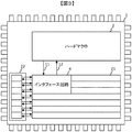
- FIG. 3 shows an example in which a configuration random access memory (CRAM) diagnostic circuit as shown in FIG. 3 is used as the PL diagnostic function described in FIG.
- FIG. 3 is different from the FPGA (1) shown in FIG. 1 in that the CRAM diagnostic circuit 22 is added to the PL (21).
- the PL (21) in FIG. 3 divides the circuit part into seven lines, and the CRAM diagnosis circuit 22 is also divided into seven parts corresponding to this, and diagnosis is performed for each corresponding line of PL (21). Do.
- the CRAM diagnostic circuit 22 is a circuit that detects an inversion of data held in each row in the PL (21) using an algorithm based on a code theory, which is generally implemented in recent SRAM type FPGAs. It can be easily implemented as a PL diagnosis method in the FPGA of the present invention.
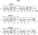
- FIG. 4 shows an example of the operation flow when a system requiring high safety is mounted using the FPGA of the present invention shown in FIGS.
- FIG. 4A is a time chart showing an example of a state in which the system is operating safely without failure.
- This system includes an RT process 51 in which the PL part hardware executes a process having a high real-time (Real-Time) property, a PL diagnosis process 52 for performing a PL diagnosis by a CRAM diagnosis circuit, etc., and a PL via an interface circuit.
- FPGA internal transfer processing 53 for transferring the PL processing data from the hard macro to the hard macro
- external output processing 54 for outputting a control signal to a device connected outside the FPGA during the disconnection of the data transfer from the PL to the hard macro by the function of the interface circuit ,
- a system that repeats five idle times 55 waiting for the next command without doing anything within one control cycle, and continues to operate normally in the first and second cycles of FIG. Is shown.
- the RT process 51 and the PL diagnosis process 52 are performed, the connection from the PL to the hard macro is disconnected by the interface circuit.
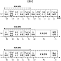
- FIG. 4 (b) is the same as the example of FIG. 4 (a) in the first period, but it is detected that a failure due to a soft error has occurred in the PL diagnosis 62 in the second period.
- FIG. 4 shows an example of transition to the safety process 70. Unlike FIG. 4A, the internal transfer process 63 and the external output process 64 are not performed, so that inadvertent data is not transmitted outside the FPGA, and the restart process is performed.
- 71 shows an example in which the system is restarted at 71 and the system operation is restarted in a state where the influence of the soft error is eliminated.
- FIG. 4C shows an example in which the system is stopped by a stop process 72 after the safety process 70 and stopped in a safe state after the safety process 70, for example, a system caused by a failure in the PL portion.
- a stop process 72 after the safety process 70 and stopped in a safe state after the safety process 70, for example, a system caused by a failure in the PL portion.
- the time chart shown in FIG. 5 has a part where the PL diagnosis processing 52 is at the head of the control cycle in all of (a), (b), and (c). Is different.
- the RT process is executed only when a failure in the PL part is not detected.
- FIGS. 1-10 an example in the case where higher security is realized without outputting illegal data outside the FPGA is shown in FIGS.
- the FPGA (301) shown in FIG. 6 includes comparators 305 and 306 in the hard macro 302, and arithmetic circuits 303 and 304 in the PL (3) portion. The part that implements is different.
- the arithmetic circuits 303 and 304 have a circuit configuration having the same function.
- the interface circuit 307 shown in FIG. 7 differs from the interface circuit 4 shown in FIG. 2 in that another data transfer determination unit 332 and an output port 333 are mounted in the data transfer control unit 331. ing.
- the data transfer determination unit 332 receives the PL data signal 322 from the arithmetic circuit 304, and the PL data signal 324 that is output from the port 333 to the hard macro (2) according to the value of the PL diagnosis result signal 17 as in the data transfer determination unit 9. Control the value of.
- the PL data signals 323 and 324 output through the interface circuit 307 of the PL (3) have the same value during the normal operation of the PL (3). These two signals are judged by the comparators 305 and 306 to determine whether or not they match, and are output from the external terminals 311 and 312 to the outside of the FPGA only when they match.
- the FPGA (401) shown in FIG. 8 is different from the FPGA (1) shown in FIG. 1 in that an internal port 403 that operates as an output and an internal port 404 that operates as an input are added to the hard macro 402. Is different.
- the built-in port 403 and the built-in port 404 are part of what is configured as the hard macro 2, and the circuit configuration cannot be changed. Therefore, the influence of the failure of the PL (3) can be transmitted to the hard macro 2 via the interface circuit 4. Even if there is a possibility, the influence of the failure can be prevented from being transmitted to the outside of the FPGA via the hard macro 402 by closing the input port 404 that can be controlled only in the hard macro 2.
- FIG. 9 (a) is a diagram showing an example of a hard macro built-in FPGA (501) mounted with a Quad Flat Package (QFP) in which external terminals are arranged on the outer periphery of the semiconductor package.
- the hard macro and programmable logic mounting areas are divided at the border.
- the hard macro portion is provided adjacent to one side of the semiconductor package and is connected only to the external terminal 503, and the other external terminals are connected to the programmable logic portion. Connected.
- FIG. 9B is a diagram showing an example of a hard macro built-in FPGA (511) mounted with a Ball Grid Array (BGA) in which external terminals are arranged on the bottom surface of the semiconductor package.
- BGA Ball Grid Array
- the hard macro portion is connected only to the external terminal 513, and the other external terminals are connected to the programmable logic.
- FIG. 10 shows an example of a cross-sectional view of the FPGA of the present invention mounted with BGA.
- An external terminal 606 for connection to the outside of the FPGA is connected to a ball bump 605 via a metal wiring layer 604.
- the hard macro layer 602 is connected to the ball bump 605.
- the programmable logic layer 603 is mounted on the hard macro layer 602 and physically separated from the ball bump 605.
- the hard macro that performs high-safe processing by limiting the circuit connected from the external terminal of the FPGA to only the hard macro part and arranging the programmable logic part and the ball bump in a three-dimensional position, Programmable logic that performs high-speed parallel processing with a high soft error occurrence probability can be implemented in a small package at a low cost.
- FIG. 10 shows an example in which the package is mounted by BGA. However, even when external terminals such as QFP are connected to the outer periphery of the package, they can be similarly stacked and mounted.
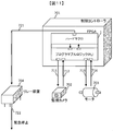
- FIG. 11 shows an example of an apparatus for controlling the power supply system, and the FPGA (1) of the present invention is mounted on one of the components constituting the control controller 701.
- the controller 701 constantly monitors the operating state of the machine responsible for power supply by the monitoring camera 702, and performs power generation control by the motor 703 connected to the power unit.
- the relay device 704 includes a relay circuit for safely and urgently stopping the power system when the system is likely to be in an abnormal state due to a failure or the like.
- an image processing circuit is mounted on the PL of the FPGA (1), and a monitoring camera control signal 711 is output from the PL of the FPGA (1) to the monitoring camera 702 for monitoring.
- a monitoring camera data signal 712 is output from the camera 702 to the PL of the FPGA (1), and image processing is performed by the PL hardware.
- a motor control circuit is mounted on the PL of the FPGA (1), and the FPGA (1) A motor control signal 713 is output from the PL to the motor 703, a motor data signal 714 is output from the motor 703 to the PL of the FPGA (1), and the motor is controlled by the PL hardware.
- the relay device 704 is responsible for an emergency stop operation in the case of a system failure or the like, and is required to operate reliably when the failure is detected, so that the system is safely stopped. Therefore, high safety is required.
- the relay control signal 721 for controlling the relay device 704 is transmitted from the hard macro portion of the FPGA (1) to the relay device 704, and in an emergency, the relay device 704 transmits the emergency stop signal 722 to the device to be stopped to transmit the system. Stop safely.
- FIG. 12 shows an example of a device constituting a railway signal system that controls the progress of a train.
- the FPGA (1) of the present invention is mounted on one of the parts constituting the railway signal controller 801. Yes.
- Train position information 811 is transmitted to the train position calculation unit 803 via the communication means such as wired or wireless as the position information during traveling of the train 805 obtained by the sensor attached to the rail portion.
- the train position data 812 calculated by the unit 803 is sent to the PL part of the FPGA (1) of the railway signal controller 801 and processed by hardware.
- the traffic light 804 is a device for notifying a train that is running in an emergency such as a failure or accident in a railway system, and it is necessary to operate reliably in an emergency to stop the train safely. Safety is required.
- a signal control signal 813 to be transmitted to the signal control unit 802 that controls the traffic light 804 is transmitted from the hard macro portion of the FPGA (1) to the signal control unit 802, and a stop instruction signal 814 is transmitted from the signal control unit 802 in an emergency.
- the train is safely stopped by transmitting to the traffic light 804 and notifying the stop.
- FIG. 13 shows an example of the configuration of an automobile driving support system that uses image information during driving for driving control, and is a component that constitutes an integrated ECU (Electric Control Unit) 930 that controls the entire automobile 901. One of them is equipped with the FPGA (1) of the present invention.
- ECU Electronic Control Unit
- the automobile 901 has a function of recognizing image information during traveling in real time by a stereo camera 902 attached to the front of the vehicle body.
- the monocular cameras 903 and 904 transmit monocular camera data signals 922 and 924 to the PL of the FPGA (1), respectively, and the PL is processed by hardware implemented based on an image processing algorithm.
- the brakes 909, 910, 911, and 912 attached to the front wheels 905 and 906 and the rear wheels 907 and 908 operate reliably in an emergency such as a system failure inside the automobile 901 to make the automobile 901 safe.
- High safety is required because it must be stopped, and if it cannot be stopped in an emergency, it may fall into a dangerous state.
- the brake control signal 925 transmitted to the brake control ECU (931) for controlling the brakes 909, 910, 911, and 912 is transmitted from the hard macro portion of the FPGA (1) to the brake control ECU (931), and in an emergency.
- a stop instruction signal 926 is transmitted from the brake control ECU (931) to each brake to stop the front wheels and the rear wheels, and the vehicle is safely stopped.
- this invention is not limited to an above-described Example, Various modifications are included.
- the above-described embodiments have been described in detail for easy understanding of the present invention, and are not necessarily limited to those having all the configurations described.
- a part of the configuration of one embodiment can be replaced with the configuration of another embodiment, and the configuration of another embodiment can be added to the configuration of one embodiment.
Landscapes
- Engineering & Computer Science (AREA)
- Physics & Mathematics (AREA)
- General Engineering & Computer Science (AREA)
- Theoretical Computer Science (AREA)
- Mathematical Physics (AREA)
- General Physics & Mathematics (AREA)
- Quality & Reliability (AREA)
- Computer Hardware Design (AREA)
- Computing Systems (AREA)
- Computer Security & Cryptography (AREA)
- Logic Circuits (AREA)
- Debugging And Monitoring (AREA)
Abstract
Priority Applications (3)
| Application Number | Priority Date | Filing Date | Title |
|---|---|---|---|
| JP2016571564A JP6430541B2 (ja) | 2015-01-28 | 2015-01-28 | フィールドプログラマブルゲートアレイ |
| US15/546,694 US10425081B2 (en) | 2015-01-28 | 2015-01-28 | Field programmable logic array |
| PCT/JP2015/052258 WO2016121015A1 (fr) | 2015-01-28 | 2015-01-28 | Circuit intégré prédiffusé programmable |
Applications Claiming Priority (1)
| Application Number | Priority Date | Filing Date | Title |
|---|---|---|---|
| PCT/JP2015/052258 WO2016121015A1 (fr) | 2015-01-28 | 2015-01-28 | Circuit intégré prédiffusé programmable |
Publications (1)
| Publication Number | Publication Date |
|---|---|
| WO2016121015A1 true WO2016121015A1 (fr) | 2016-08-04 |
Family
ID=56542672
Family Applications (1)
| Application Number | Title | Priority Date | Filing Date |
|---|---|---|---|
| PCT/JP2015/052258 Ceased WO2016121015A1 (fr) | 2015-01-28 | 2015-01-28 | Circuit intégré prédiffusé programmable |
Country Status (3)
| Country | Link |
|---|---|
| US (1) | US10425081B2 (fr) |
| JP (1) | JP6430541B2 (fr) |
| WO (1) | WO2016121015A1 (fr) |
Cited By (3)
| Publication number | Priority date | Publication date | Assignee | Title |
|---|---|---|---|---|
| JP2018029267A (ja) * | 2016-08-18 | 2018-02-22 | 富士通株式会社 | プログラマブルロジック装置、情報処理装置、処理方法、及び処理プログラム |
| WO2018230149A1 (fr) * | 2017-06-12 | 2018-12-20 | 日立オートモティブシステムズ株式会社 | Dispositif de commande électronique, système embarqué et dispositif d'alimentation électrique |
| JP7575545B2 (ja) | 2022-08-03 | 2024-10-29 | ベイカー ヒューズ ホールディングス エルエルシー | Fpgaリレーシステム上のブールリレー論理でのリレー再フラッシュ検出及び伝搬 |
Families Citing this family (2)
| Publication number | Priority date | Publication date | Assignee | Title |
|---|---|---|---|---|
| JP6546213B2 (ja) * | 2017-04-13 | 2019-07-17 | ファナック株式会社 | 回路構成最適化装置及び機械学習装置 |
| CN116258107B (zh) * | 2023-02-21 | 2025-12-02 | 上海安路信息科技股份有限公司 | Fpga硬宏单元的初始位置布局方法和装置 |
Citations (3)
| Publication number | Priority date | Publication date | Assignee | Title |
|---|---|---|---|---|
| JP2007058419A (ja) * | 2005-08-23 | 2007-03-08 | Hitachi Ltd | Pld上のメモリ内の情報に従って構築される論理回路を備えたストレージシステム |
| JP2009017010A (ja) * | 2007-07-02 | 2009-01-22 | Nec Electronics Corp | 再構成可能デバイス |
| JP2012099760A (ja) * | 2010-11-05 | 2012-05-24 | Nec Corp | プログラマブルゲートアレイおよびプログラマブルゲートアレイのプログラミング方法 |
Family Cites Families (10)
| Publication number | Priority date | Publication date | Assignee | Title |
|---|---|---|---|---|
| GB8626516D0 (en) * | 1986-11-06 | 1986-12-10 | Int Computers Ltd | Testing programmable logic arrays |
| US6530049B1 (en) | 2000-07-06 | 2003-03-04 | Lattice Semiconductor Corporation | On-line fault tolerant operation via incremental reconfiguration of field programmable gate arrays |
| US7036059B1 (en) * | 2001-02-14 | 2006-04-25 | Xilinx, Inc. | Techniques for mitigating, detecting and correcting single event upset effects in systems using SRAM-based field programmable gate arrays |
| US6744274B1 (en) * | 2001-08-09 | 2004-06-01 | Stretch, Inc. | Programmable logic core adapter |
| JP4643977B2 (ja) * | 2004-11-30 | 2011-03-02 | 富士通株式会社 | プログラマブル・ロジック・デバイス、情報処理装置、プログラマブル・ロジック・デバイスの制御方法 |
| JP2007243671A (ja) * | 2006-03-09 | 2007-09-20 | Kddi Corp | 論理プログラマブルデバイス保護回路 |
| US7573295B1 (en) * | 2007-05-14 | 2009-08-11 | Xilinx, Inc. | Hard macro-to-user logic interface |
| US7800404B2 (en) * | 2007-12-05 | 2010-09-21 | Integrated Device Technology, Inc. | Field programmable application specific integrated circuit with programmable logic array and method of designing and programming the programmable logic array |
| US8117512B2 (en) * | 2008-02-06 | 2012-02-14 | Westinghouse Electric Company Llc | Failure detection and mitigation in logic circuits |
| US8306563B2 (en) * | 2009-01-29 | 2012-11-06 | Adc Telecommunications, Inc. | Method and apparatus for muting a digital link in a distributed antenna system |
-
2015
- 2015-01-28 JP JP2016571564A patent/JP6430541B2/ja not_active Expired - Fee Related
- 2015-01-28 WO PCT/JP2015/052258 patent/WO2016121015A1/fr not_active Ceased
- 2015-01-28 US US15/546,694 patent/US10425081B2/en not_active Expired - Fee Related
Patent Citations (3)
| Publication number | Priority date | Publication date | Assignee | Title |
|---|---|---|---|---|
| JP2007058419A (ja) * | 2005-08-23 | 2007-03-08 | Hitachi Ltd | Pld上のメモリ内の情報に従って構築される論理回路を備えたストレージシステム |
| JP2009017010A (ja) * | 2007-07-02 | 2009-01-22 | Nec Electronics Corp | 再構成可能デバイス |
| JP2012099760A (ja) * | 2010-11-05 | 2012-05-24 | Nec Corp | プログラマブルゲートアレイおよびプログラマブルゲートアレイのプログラミング方法 |
Cited By (4)
| Publication number | Priority date | Publication date | Assignee | Title |
|---|---|---|---|---|
| JP2018029267A (ja) * | 2016-08-18 | 2018-02-22 | 富士通株式会社 | プログラマブルロジック装置、情報処理装置、処理方法、及び処理プログラム |
| WO2018230149A1 (fr) * | 2017-06-12 | 2018-12-20 | 日立オートモティブシステムズ株式会社 | Dispositif de commande électronique, système embarqué et dispositif d'alimentation électrique |
| US11192507B2 (en) | 2017-06-12 | 2021-12-07 | Hitachi Astemo, Ltd. | Electronic control device, in-vehicle system, and power supply device |
| JP7575545B2 (ja) | 2022-08-03 | 2024-10-29 | ベイカー ヒューズ ホールディングス エルエルシー | Fpgaリレーシステム上のブールリレー論理でのリレー再フラッシュ検出及び伝搬 |
Also Published As
| Publication number | Publication date |
|---|---|
| JP6430541B2 (ja) | 2018-11-28 |
| US20180278254A1 (en) | 2018-09-27 |
| JPWO2016121015A1 (ja) | 2017-10-19 |
| US10425081B2 (en) | 2019-09-24 |
Similar Documents
| Publication | Publication Date | Title |
|---|---|---|
| JP6464263B2 (ja) | フィールドプログラマブルゲートアレイ | |
| JP6430541B2 (ja) | フィールドプログラマブルゲートアレイ | |
| US10576990B2 (en) | Method and device for handling safety critical errors | |
| US10120772B2 (en) | Operation of I/O in a safe system | |
| WO2017107665A1 (fr) | Système informatique de sécurité destiné à être utilisé dans la commande de trains | |
| CN113015666A (zh) | 用于车辆的控制架构 | |
| US9367375B2 (en) | Direct connect algorithm | |
| JP6222362B2 (ja) | 電力変換装置 | |
| JP6861302B2 (ja) | 車両制御装置および電子制御システム | |
| US10120742B2 (en) | Power supply controller system and semiconductor device | |
| JP2016147585A (ja) | 電子制御装置 | |
| US9665447B2 (en) | Fault-tolerant failsafe computer system using COTS components | |
| CN104281557A (zh) | 具有至少两个核的微控制器 | |
| CN110837233B (zh) | 一种提高功能安全性的安全控制系统 | |
| AU2012323190A1 (en) | Method for operating a control network, and control network | |
| JP2017228159A (ja) | 制御装置、および制御装置の制御方法 | |
| Hayek et al. | Design and implementation of an FPGA-based 1oo4-architecture for safety-related system-on-chips | |
| US20230176538A1 (en) | Solid state power controllers | |
| KR20110020429A (ko) | 정보교환을 통한 개별적인 이중 방식 이씨유 고장 판단방법 | |
| JP6685187B2 (ja) | 電子制御装置 | |
| CN116062025A (zh) | 线控转向装置的冗余备份系统及其控制方法和车辆 | |
| JP2011248625A (ja) | 制御装置の故障診断回路および故障診断方法 | |
| US20250094277A1 (en) | Method for low latency fail-operational time sensitive networking | |
| CN116198735A (zh) | 飞行器的控制方法、飞行器及计算机可读存储介质 | |
| KR101808618B1 (ko) | 철도시스템 기반의 고 안전성 이중화 시스템 |
Legal Events
| Date | Code | Title | Description |
|---|---|---|---|
| 121 | Ep: the epo has been informed by wipo that ep was designated in this application |
Ref document number: 15879912 Country of ref document: EP Kind code of ref document: A1 |
|
| ENP | Entry into the national phase |
Ref document number: 2016571564 Country of ref document: JP Kind code of ref document: A |
|
| WWE | Wipo information: entry into national phase |
Ref document number: 15546694 Country of ref document: US |
|
| NENP | Non-entry into the national phase |
Ref country code: DE |
|
| 122 | Ep: pct application non-entry in european phase |
Ref document number: 15879912 Country of ref document: EP Kind code of ref document: A1 |