WO2016121252A1 - Dispositif et procédé - Google Patents
Dispositif et procédé Download PDFInfo
- Publication number
- WO2016121252A1 WO2016121252A1 PCT/JP2015/084947 JP2015084947W WO2016121252A1 WO 2016121252 A1 WO2016121252 A1 WO 2016121252A1 JP 2015084947 W JP2015084947 W JP 2015084947W WO 2016121252 A1 WO2016121252 A1 WO 2016121252A1
- Authority
- WO
- WIPO (PCT)
- Prior art keywords
- power
- subframe
- terminal device
- frequency band
- related information
- Prior art date
- Legal status (The legal status is an assumption and is not a legal conclusion. Google has not performed a legal analysis and makes no representation as to the accuracy of the status listed.)
- Ceased
Links
Images







Classifications
-
- H—ELECTRICITY
- H04—ELECTRIC COMMUNICATION TECHNIQUE
- H04W—WIRELESS COMMUNICATION NETWORKS
- H04W16/00—Network planning, e.g. coverage or traffic planning tools; Network deployment, e.g. resource partitioning or cells structures
- H04W16/24—Cell structures
- H04W16/28—Cell structures using beam steering
-
- H—ELECTRICITY
- H04—ELECTRIC COMMUNICATION TECHNIQUE
- H04W—WIRELESS COMMUNICATION NETWORKS
- H04W52/00—Power management, e.g. Transmission Power Control [TPC] or power classes
- H04W52/04—Transmission power control [TPC]
- H04W52/54—Signalisation aspects of the TPC commands, e.g. frame structure
Definitions
- the present disclosure relates to an apparatus and a method.
- the base station performs beam forming using a directional antenna including a large number of antenna elements (for example, about 100 antenna elements).
- a technique is a form of a technique called large-scale MIMO or massive MIMO.
- the half width of the beam becomes narrow. That is, a sharp beam is formed.
- by arranging the multiple antenna elements on a plane it is possible to form a beam in a desired three-dimensional direction.
- Patent Documents 1 to 3 disclose techniques applied when a directional beam in a three-dimensional direction is used.
- the number of directional beams formed at the same time eg, large-scale MIMO directional beams
- the power allocated to each directional beam also changes dynamically
- the terminal device's ACG Automatic Gain Control
- reception quality can be degraded.
- an acquisition unit that acquires power-related information regarding power according to the number of directional beams formed in a subframe in a frequency band, and a downlink transmitted in the subframe in the frequency band
- a device includes a control unit that notifies the terminal device of the power-related information in the control information.
- the processor acquires power-related information regarding power according to the number of directional beams formed in a subframe in a frequency band, and transmits the power in the subframe in the frequency band. And notifying the terminal device of the power related information in the downlink control information to be provided.
- An apparatus comprising: an acquisition unit that acquires the power-related information notified from the base station to the terminal device in the information; and a control unit that performs gain setting of the reception amplifier of the terminal device based on the power-related information.
- the processor is power-related information related to power according to the number of directional beams formed in a subframe in a frequency band, and is transmitted in the subframe in the frequency band.
- a method comprising: acquiring the power related information notified to a terminal device by a base station in downlink control information; and setting a gain of a receiving amplifier of the terminal device based on the power related information. Is provided.
- the present disclosure it is possible to obtain better reception quality when transmission using a directional beam is performed.
- the above effects are not necessarily limited, and any of the effects shown in the present specification or other effects that can be grasped from the present specification are exhibited together with or in place of the above effects. May be.
- FIG. 6 is an explanatory diagram for explaining a flow of processing for setting an LNA gain; It is explanatory drawing for demonstrating an example of the stop of transmission of a downlink data signal. It is explanatory drawing for demonstrating an example of the electric power after the transmission of a downlink data signal is stopped. It is a sequence diagram showing an example of a schematic flow of processing according to the embodiment.
- 8-layer MIMO can be realized in the case of SU-MIMO (Single-User Multi-Input Multiple-Input Multiple-Output).
- 8-layer MIMO is a technique for spatially multiplexing eight independent streams.
- two layers of MU-MIMO can be realized for four users.
- UE User Equipment
- the base station performs beam forming using a directional antenna including a large number of antenna elements (for example, about 100 antenna elements).
- a technique is one form of a technique called large-scale MIMO or massive MIMO.
- the half width of the beam becomes narrow. That is, a sharp beam is formed.
- by arranging the multiple antenna elements on a plane it is possible to form a beam in a desired three-dimensional direction. For example, it has been proposed to transmit a signal to a terminal device existing at the position by forming a beam directed to a position higher than the base station (for example, an upper floor of a high-rise building).
- the typical beam forming In typical beam forming, it is possible to change the beam direction in the horizontal direction. Therefore, it can be said that the typical beam forming is two-dimensional beam forming.
- the beam direction can be changed in the vertical direction in addition to the horizontal direction. Therefore, it can be said that large-scale MIMO beamforming is three-dimensional beamforming.
- MU-MIMO since the number of antennas increases, the number of users in MU-MIMO can be increased.
- Such a technique is another form of a technique called large scale MIMO or massive MIMO.
- the number of antennas of the UE is two, the number of spatially independent streams for one UE is two, and therefore, MU-MIMO rather than increasing the number of streams for one UE. It is more reasonable to increase the number of users.
- Weight set A weight set for beam forming (that is, a set of weight coefficients for a plurality of antenna elements) is expressed as a complex number.
- a weight set for beam forming of large scale MIMO will be described with reference to FIG.
- FIG. 1 is an explanatory diagram for describing a weight set for large-scale MIMO beamforming.
- antenna elements arranged in a lattice shape are shown. Also shown are two axes x, y orthogonal to the plane on which the antenna element is arranged, and one axis z orthogonal to the plane.
- the direction of the beam to be formed is represented by, for example, an angle phi (Greek letter) and an angle theta (Greek letter).
- the angle phi (Greek letter) is an angle formed between the x-axis component and the xy plane component in the beam direction.
- the angle theta (Greek letter) is an angle formed by the beam direction and the z axis.
- the weighting factor V m, n of the antenna element arranged m-th in the x-axis direction and n-th arranged in the y-axis direction can be expressed as follows.
- f is the frequency and c is the speed of light.
- J is an imaginary unit in a complex number.
- D x is the distance between the antenna elements in the x-axis direction, and dy is the distance between the antenna elements in the y-axis direction.
- the coordinates of the antenna element are expressed as follows.
- the result of the above measurement is used to select a cell for the terminal device. Specifically, for example, the result of the measurement is used for cell selection / cell reselection by a terminal device that is RRC (Radio Resource Control) idle (RRC Idle). Further, for example, the result of the measurement is reported to the base station by a terminal device that is RRC connected (RRC Connected), and is used for handover determination (Handover Decision) by the base station.
- RRC Radio Resource Control
- the measurement is performed by receiving CRS. Since the CRS is a signal for measuring the quality of a non-directional radio wave transmission path, the CRS is transmitted without beamforming. That is, the CRS is transmitted without being multiplied by the beamforming weight set.
- DM-RS Demodulation Reference Signal
- UE-specific reference signal UE-specific Reference Signal
- CSI-RS Channel State Information Reference Signal
- FIG. 3 is an explanatory diagram for explaining the relationship between weighting coefficient multiplication and reference signal insertion.
- the transmission signal 82 corresponding to each antenna element 81 is complex-multiplied by a weight coefficient 83 in a multiplier 84. Then, a transmission signal 82 obtained by complex multiplication of the weighting coefficient 83 is transmitted from the antenna element 81.
- the DR-MS 85 is inserted before the multiplier 84, and the multiplier 84 multiplies the weight coefficient 83 by a complex multiplication. Then, the DR-MS 85 obtained by complex multiplication of the weight coefficient 83 is transmitted from the antenna element 81.
- the CRS 86 (and CSI-RS) is inserted after the multiplier 84. The CRS 86 (and CSI-RS) is transmitted from the antenna element 81 without being multiplied by the weighting coefficient 83.
- CRS measurements are RSRP (Reference Signal Received Power) and / or RSRQ (Reference Signal Received Quality) measurements.
- the terminal device acquires RSRP and / or RSRQ as a result of measurement on CRS.
- RSRQ is calculated from RSRP and RSSI (Received Signal Strength Indicator).
- the reception power that is, RSRP
- the reception quality that is, RSRQ
- SINR the reception quality
- reception quality (that is, RSRQ) is often used in cell selection described later. This is because if a cell is selected based only on received power (ie, RSRP), a cell with large interference can be selected.
- the base station makes a handover decision. That is, the base station selects a target cell for the terminal device and determines a handover from the serving cell for the terminal device to the target cell.
- the base station adds a Scell (Secondary Cell) for carrier aggregation.
- the Scell is also called SCC (Secondary Component Carrier).
- the “cell” here may mean a communication area of the base station, or may mean a frequency band used by the base station.
- the “cell” here may be a Pcell (Primary Cell) or Scell of carrier aggregation.
- the Pcell is also called PCC (Primary Component Carrier), and the Scell is also called SCC (Secondary Component Carrier).
- the base station has a large number of antenna elements (for example, about 100 antenna elements). Beam forming is performed using a directional antenna including In this case, the base station can change the beam direction not only in the horizontal direction but also in the vertical direction. Therefore, as an example, the base station can improve the throughput at a high position by forming a beam toward a position higher than the base station (for example, an upper floor of a high-rise building). As another example, a small base station can reduce interference with neighboring base stations by forming a beam to a nearby area.
- a terminal apparatus transmits and receives a signal in a cell selected based on a CRS measurement result
- a larger interference occurs in a sharp beam from an adjacent base station.
- the result of CRS measurement for one cell is better than the result of CRS measurement for another cell, if beamforming is performed, There is a possibility that the communication quality is better than the communication quality in a certain cell.
- an appropriate cell may not be selected for the terminal device when beamforming is performed.
- the measurement result (reception power / reception quality) for CRS is the reception of a data signal transmitted by a directional beam.
- the power / reception quality can vary greatly. In order to solve this, it is conceivable to transmit the CRS using a directional beam.
- a specific example of this point will be described with reference to FIG.
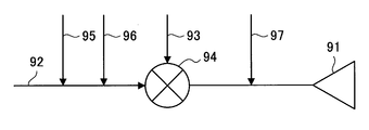
- FIG. 4 is an explanatory diagram for explaining another relationship between weighting coefficient multiplication and reference signal insertion.
- transmission signal 92 corresponding to each antenna element 91 is complex-multiplied by weighting factor 93 in multiplier 94.
- a transmission signal 92 obtained by complex multiplication of the weight coefficient 93 is transmitted from the antenna element 91.
- the DR-MS 95 is inserted in front of the multiplier 94, and the multiplier 94 multiplies the weight coefficient 93 in a complex manner.
- the DR-MS 95 obtained by complex multiplication of the weight coefficient 93 is transmitted from the antenna element 91.
- the CRS 96 is inserted before the multiplier 94, and the weight coefficient 93 is complex-multiplied by the multiplier 94. Then, the CRS 96 obtained by complex multiplication of the weight coefficient 93 is transmitted from the antenna element 91.
- a normal CRS 97 (and CSI-RS) is inserted after the multiplier 94. The normal CRS 97 (and CSI-RS) is transmitted from the antenna element 91 without being multiplied by the weight coefficient 93.
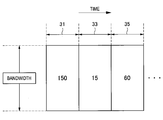
- FIG. 5 is an explanatory diagram for explaining an example of the number of directional beams formed in each subframe.
- a frequency band eg, component carrier
- 150 directional beams are formed in the frequency band.
- 15 directional beams are formed in the frequency band
- 60 directional beams are formed in the frequency band. Since there is an upper limit on the transmission power of the base station, if there are many directional beams formed in a subframe, the power allocated to each directional beam will be small, and there will be fewer directional beams formed in the subframe. For example, the power allocated to each directional beam increases.
- the number of directional beams formed in the subframe 33 is 1/10 of the number of directional beams formed in the subframe 31, and thus the directivity formed in the subframe 33.
- the power allocated to the beam is increased by 10 dB.
- the received power at the terminal device also increases.
- the number of directional beams formed in the subframe 35 is four times the number of directional beams formed in the subframe 33, and thus the directional beams formed in the subframe 33.
- the power allocated to is reduced by 6.02 dB. As a result, the received power in the terminal device is also reduced.
- FIG. 6 is an explanatory diagram for explaining an example of a dynamic range and received power.
- a change in received power 41 within the dynamic range in the terminal device is shown.
- the directional beam suddenly decreases, and as a result, the reception power 41 in the terminal apparatus also increases rapidly.
- saturation occurs in an A / D (Analog-Digital) converter, and the terminal device may not be able to receive signals properly.
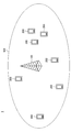
- FIG. 7 is an explanatory diagram illustrating an example of a schematic configuration of the system 1 according to the embodiment of the present disclosure.
- the system 1 includes a base station 100 and a terminal device 200.
- the system 1 is, for example, a system that complies with LTE, LTE-Advanced, or a communication standard based on these.
- the base station 100 performs wireless communication with the terminal device 200.
- the base station 100 performs wireless communication with the terminal device 200 located in the cell 101 of the base station 100.
- the base station 100 performs beam forming.
- the beam forming is large-scale MIMO beam forming.
- the beam forming may also be referred to as massive MIMO beam forming, free dimension MIMO beam forming, or three-dimensional beam forming.
- the base station 100 includes a directional antenna that can be used for large-scale MIMO, and performs large-scale MIMO beamforming by multiplying a transmission signal by a weight set for the directional antenna. .
- the terminal device 200 performs wireless communication with the base station 100. For example, when the terminal device 200 is located in the cell 101 of the base station 100, the terminal device 200 performs wireless communication with the base station 100.
- FIG. 8 is a block diagram illustrating an exemplary configuration of the base station 100 according to the embodiment of the present disclosure.
- the base station 100 includes an antenna unit 110, a wireless communication unit 120, a network communication unit 130, a storage unit 140, and a processing unit 150.
- the antenna unit 110 radiates the signal output from the wireless communication unit 120 to the space as a radio wave. Further, the antenna unit 110 converts radio waves in space into a signal and outputs the signal to the wireless communication unit 120.
- the antenna unit 110 includes a directional antenna.
- the directional antenna is a directional antenna that can be used for large scale MIMO.
- the wireless communication unit 120 transmits and receives signals.
- the radio communication unit 120 transmits a downlink signal to the terminal device 200 and receives an uplink signal from the terminal device 200.
- the network communication unit 130 transmits and receives information.
- the network communication unit 130 transmits information to other nodes and receives information from other nodes.
- the other nodes include other base stations and core network nodes.
- the storage unit 140 stores a program and data for the operation of the base station 100.
- the processing unit 150 provides various functions of the base station 100.
- the processing unit 150 includes an information acquisition unit 151 and a control unit 153.
- the processing unit 150 may further include other components other than these components. That is, the processing unit 150 can perform operations other than the operations of these components.
- FIG. 9 is a block diagram illustrating an exemplary configuration of the terminal device 200 according to an embodiment of the present disclosure.
- the terminal device 200 includes an antenna unit 210, a wireless communication unit 220, a storage unit 230, and a processing unit 240.
- the antenna unit 210 radiates the signal output from the wireless communication unit 220 to the space as a radio wave. Further, the antenna unit 210 converts a radio wave in the space into a signal and outputs the signal to the wireless communication unit 220.
- the wireless communication unit 220 transmits and receives signals.
- the radio communication unit 220 receives a downlink signal from the base station 100 and transmits an uplink signal to the base station 100.
- the storage unit 230 stores a program and data for the operation of the terminal device 200.
- the processing unit 240 provides various functions of the terminal device 200.
- the processing unit 240 includes an information acquisition unit 241 and a control unit 243. Note that the processing unit 240 may further include other components other than these components. That is, the processing unit 240 can perform operations other than the operations of these components.
- the base station 100 acquires power-related information regarding power according to the number of directional beams formed in a subframe in a frequency band. Then, the base station 100 (the control unit 153) notifies the terminal device 200 of the power related information in downlink control information (DCI) transmitted in the subframe in the frequency band. .
- DCI downlink control information
- the terminal device 200 acquires the power related information. And the terminal device 200 (control part 243) sets the gain of the receiving amplifier of the terminal device 200 based on the said electric power related information.
- the power related information is information indicating a power offset corresponding to the number of the directional beams.
- the power offset can be said to be a power reduction amount per directional beam.
- the directional beam is a large-scale MIMO directional beam.
- the power offset is 0 dB
- the power offset is ⁇ 3.01 dB
- the power offset is ⁇ 6.02 dB.
- the terminal device 200 can more easily know how much received power will be, and can perform an appropriate gain setting.
- the power related information is an index indicating the power offset.
- the power related information is an index indicating the power offset.
- FIG. 10 is an explanatory diagram for explaining an example of power-related information indicating a power offset.
- the index and power offset are shown.
- a plurality of power offsets are defined, and each index indicates a corresponding one of the plurality of power offsets.
- index 0 indicates 0 dB
- index 2 indicates ⁇ 6.02 dB.
- the power related information is one of a plurality of indexes, and indicates one of the plurality of power offsets. Note that information indicating the relationship between such an index and a power offset is held in the base station 100 and the terminal device 200.
- the power related information may be information indicating something other than the power offset.
- the power related information may be information indicating the number of the directional beams.
- the power related information may be an index indicating the number of the directional beams.
- information indicating the relationship between the index and the number of directional beams (and information indicating the relationship between the number of directional beams and the power offset) may be held in the base station 100 and the terminal device 200.
- the terminal device 200 can know how much the received power is, and can perform an appropriate gain setting.
- Terminal apparatus (a) Terminal apparatus to which resources are allocated
- the terminal apparatus 200 to which the base station 100 notifies the power-related information is a terminal apparatus to which downlink resources in the subframe are allocated. That is, the terminal device 200 is a terminal device that receives a downlink data signal within the subframe.
- the terminal device 200 from which the base station 100 notifies the power-related information is a device having the capability of setting the gain of the receiving amplifier based on the power-related information.
- the terminal device 200 (the control unit 243) notifies the base station 100 of capability information indicating that the terminal device 200 has the capability. Then, the base station 100 (information acquisition unit 151) acquires the capability information.
- the base station 100 (the control unit 153) notifies the terminal device 200 of the power related information in the downlink control information transmitted in the subframe in the frequency band. To do.
- the downlink control information includes information indicating downlink resources allocated to the terminal device 200.
- the downlink control information is information transmitted on a physical downlink control channel (Physical Downlink Control Channel: PDCCH).
- PDCCH Physical Downlink Control Channel
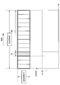
- FIG. 11 is an explanatory diagram for explaining an example of a PDCCH in which downlink control information is transmitted.
- downlink resources for one subframe in the frequency band are shown.
- the frequency band is a component carrier.
- the PDCCH is arranged in the first three symbols, and the PDSCH is arranged in the remaining 11 symbols.
- Downlink control information is transmitted on the PDCCH.
- the terminal device 200 can set the gain of the reception amplifier near the start of the subframe and perform the reception process in the subframe. Become. As a result, the received signal falls within the dynamic range of the A / D converter, and the downlink data signal transmitted by the directional beam can be appropriately received.
- the physical downlink control channel may be ePDCCH instead of normal PDCCH.
- the base station 100 transmits a downlink data signal to the terminal device 200 by a directional beam. More specifically, for example, the base station 100 transmits a downlink data signal to the terminal device 200 using a directional beam on the PDSCH. For example, a different directional beam is formed for each terminal device 200.
- the terminal device 200 sets the gain of the reception amplifier of the terminal device 200 based on the power-related information.
- the receiving amplifier is an LNA (Low Noise Amplifier).
- the terminal device 200 decreases the gain setting value of the reception amplifier when the power offset indicated by the power related information decreases, and receives the reception when the power offset indicated by the power related information increases. Increase the gain setting of the amplifier.
- FIG. 12 is an explanatory diagram for explaining the flow of LNA gain setting processing.
- a signal received by an antenna element is amplified by an LNA, converted into a digital signal by an A / D converter, and demodulated. Then, the power related information included in the downlink control information is acquired, and the LNA gain is set based on the power related information.
- the base station 100 (the control unit 153) transmits a downlink within a predetermined time after transmission of the downlink control information in the subframe in the frequency band. Stop sending data signals.
- the predetermined time is one symbol after transmission of the downlink control information in the subframe. More specifically, for example, the predetermined time is one symbol immediately after the physical downlink control channel in the subframe.
- the predetermined time is one symbol immediately after the physical downlink control channel in the subframe.
- the base station 100 may allocate power for the predetermined time as power for another time in the subframe after the predetermined time.
- the control unit 153 may allocate power for the predetermined time as power for another time in the subframe after the predetermined time.
- FIG. 14 is an explanatory diagram for explaining an example of power after transmission of a downlink data signal is stopped.
- downlink resources for one subframe in the frequency band are shown.
- the base station 100 stops the transmission of the downlink data signal within the symbol 51 (that is, the fourth symbol) immediately after the PDCCH.
- the power for the symbol 51 is allocated as the power for the symbol 53 immediately after the symbol 51 (that is, 10 symbols immediately after the symbol 51).
- the power of the symbol 53 is 11/10 times.
- the power for the symbol 51 may be allocated as power for three symbols immediately after the symbol 51 (that is, a symbol in the same slot). As a result, the power of the three symbols may be 4/3 times.
- the base station 100 (control unit 153) indicates that the power-related information notified to the terminal device 200 in the subframe in the frequency band is the subband in the frequency band.
- transmission of the downlink data signal may be stopped within the predetermined time in the frequency band.
- the base station 100 (the control unit 153) does not stop transmission of the downlink data signal within the predetermined time in the frequency band when the power related information is the same as the other power related information. May be.
- the base station 100 when the power control information is index 4 indicating -12.04 dB and the other power control information is index 0 indicating 0 dB, the base station 100 (control unit 153) Transmission of the downlink data signal may be stopped within the predetermined time in the frequency band.
- both the power control information and the other power control information are index 4 indicating ⁇ 12.04 dB
- the base station 100 when both the power control information and the other power control information are index 4 indicating ⁇ 12.04 dB, the base station 100 (the control unit 153) is down within the predetermined time in the frequency band. The transmission of the link data signal may not be stopped. This is because the gain setting value in the terminal device 200 does not change.
- the base station 100 (the control unit 153) indicates stop information indicating whether or not to stop the transmission of the downlink data signal within the predetermined time in the frequency band in the downlink control information. May be notified. Then, the terminal device 200 (information acquisition unit 241) may acquire the stop information, and the terminal device 200 (control unit 243) receives the reception in the subframe in the frequency band based on the stop information. Processing may be performed. Thereby, for example, the terminal apparatus 200 can more easily know whether or not to perform gain setting.
- FIG. 15 is a sequence diagram illustrating an example of a schematic flow of a process according to the embodiment of the present disclosure.
- the terminal device 200 notifies the base station 100 of capability information indicating that the terminal device 200 has the capability of setting the gain of the reception amplifier based on the power-related information (S401).
- the base station 100 performs resource allocation within the subframe for the frequency band (S403).
- the base station 100 notifies the terminal device 200 of the power related information and the stop information in the downlink control information transmitted in the subframe in the frequency band (S407). In other words, the base station 100 transmits downlink control information including the power related information and the stop information to the terminal device 200 within the subframe in the frequency band.
- the terminal device 200 acquires the power related information and the stop information (S409).
- the terminal device 200 sets the gain of the receiving amplifier of the terminal device 200 based on the power related information (S411).
- the base station 100 transmits a downlink data signal to the terminal device 200 using a directional beam within the subframe in the frequency band (S413).
- the directional beam is a large-scale MIMO directional beam.
- the terminal device 200 performs reception processing in the subframe in the frequency band based on the stop information (S415).
- the number of directional beams is reduced from 150 to 15.
- the base station 100 forms a 150 directional beam in the first subframe and forms a 15 directional beam in the second subframe.
- the base station 100 gradually increases the power per directional beam over a plurality of subframes without increasing the power per directional beam by 10 dB all at once in the second subframe. Increase to.
- the power per directional beam does not increase significantly between consecutive subframes. Therefore, the AGC can follow the change in received power, and the occurrence of saturation in the A / D converter is avoided.
- the number of directional beams increases from 15 to 150.
- the base station 100 forms 15 directional beams in the first subframe, and gradually increases the number of directional beams over a plurality of subframes including the second subframe. Let The base station 100 does not significantly increase the number of directional beams in the second subframe. As a result, the power per directional beam is not significantly reduced between consecutive subframes. Therefore, the AGC can follow the change in the received power, and the signal deterioration in the A / D converter is avoided.
- the base station 100 (the control unit 153), in particular, allocates the downlink resources of both the first subframe and the second subframe to the terminal device that does not have the capability. Resource allocation or power allocation may be performed so as not to exceed the predetermined threshold.
- the base station 100 may be realized as any type of eNB (evolved Node B) such as a macro eNB or a small eNB.
- the small eNB may be an eNB that covers a cell smaller than a macro cell, such as a pico eNB, a micro eNB, or a home (femto) eNB.
- the base station 100 may be realized as another type of base station such as a NodeB or a BTS (Base Transceiver Station).
- Base station 100 may include a main body (also referred to as a base station apparatus) that controls radio communication, and one or more RRHs (Remote Radio Heads) that are arranged at locations different from the main body. Further, various types of terminals described later may operate as the base station 100 by temporarily or semi-permanently executing the base station function. Furthermore, at least some components of the base station 100 may be realized in a base station apparatus or a module for the base station apparatus.
- RRHs Remote Radio Heads
- the terminal device 200 is a smartphone, a tablet PC (Personal Computer), a notebook PC, a portable game terminal, a mobile terminal such as a portable / dongle type mobile router or a digital camera, or an in-vehicle terminal such as a car navigation device. It may be realized as.
- the terminal device 200 may be realized as a terminal (also referred to as an MTC (Machine Type Communication) terminal) that performs M2M (Machine To Machine) communication.
- MTC Machine Type Communication
- M2M Machine To Machine
- at least a part of the components of the terminal device 200 may be realized in a module (for example, an integrated circuit module configured by one die) mounted on these terminals.
- FIG. 16 is a block diagram illustrating a first example of a schematic configuration of an eNB to which the technology according to the present disclosure may be applied.
- the eNB 800 includes one or more antennas 810 and a base station device 820. Each antenna 810 and the base station apparatus 820 can be connected to each other via an RF cable.
- Each of the antennas 810 has a single or a plurality of antenna elements (for example, a plurality of antenna elements constituting a MIMO antenna), and is used for transmission and reception of radio signals by the base station apparatus 820.
- the eNB 800 includes a plurality of antennas 810 as illustrated in FIG. 16, and the plurality of antennas 810 may respectively correspond to a plurality of frequency bands used by the eNB 800, for example.
- FIG. 16 illustrates an example in which the eNB 800 includes a plurality of antennas 810, the eNB 800 may include a single antenna 810.
- the base station apparatus 820 includes a controller 821, a memory 822, a network interface 823, and a wireless communication interface 825.
- the controller 821 may be a CPU or a DSP, for example, and operates various functions of the upper layer of the base station apparatus 820. For example, the controller 821 generates a data packet from the data in the signal processed by the wireless communication interface 825, and transfers the generated packet via the network interface 823. The controller 821 may generate a bundled packet by bundling data from a plurality of baseband processors, and may transfer the generated bundled packet. In addition, the controller 821 is a logic that executes control such as radio resource control, radio bearer control, mobility management, inflow control, or scheduling. May have a typical function. Moreover, the said control may be performed in cooperation with a surrounding eNB or a core network node.
- the memory 822 includes RAM and ROM, and stores programs executed by the controller 821 and various control data (for example, terminal list, transmission power data, scheduling data, and the like).
- the network interface 823 is a communication interface for connecting the base station device 820 to the core network 824.
- the controller 821 may communicate with the core network node or other eNB via the network interface 823.
- the eNB 800 and the core network node or another eNB may be connected to each other by a logical interface (for example, an S1 interface or an X2 interface).
- the network interface 823 may be a wired communication interface or a wireless communication interface for wireless backhaul.
- the network interface 823 may use a frequency band higher than the frequency band used by the wireless communication interface 825 for wireless communication.
- the wireless communication interface 825 supports any cellular communication scheme such as LTE (Long Term Evolution) or LTE-Advanced, and provides a wireless connection to terminals located in the cell of the eNB 800 via the antenna 810.
- the wireless communication interface 825 may typically include a baseband (BB) processor 826, an RF circuit 827, and the like.
- the BB processor 826 may perform, for example, encoding / decoding, modulation / demodulation, and multiplexing / demultiplexing, and each layer (for example, L1, MAC (Medium Access Control), RLC (Radio Link Control), and PDCP).
- Various signal processing of Packet Data Convergence Protocol
- Packet Data Convergence Protocol is executed.
- the radio communication interface 825 includes a plurality of BB processors 826 as illustrated in FIG. 16, and the plurality of BB processors 826 may respectively correspond to a plurality of frequency bands used by the eNB 800, for example. Further, the wireless communication interface 825 includes a plurality of RF circuits 827 as shown in FIG. 16, and the plurality of RF circuits 827 may correspond to, for example, a plurality of antenna elements, respectively. 16 shows an example in which the wireless communication interface 825 includes a plurality of BB processors 826 and a plurality of RF circuits 827, the wireless communication interface 825 includes a single BB processor 826 or a single RF circuit 827. But you can.
- the wireless communication unit 120 described with reference to FIG. 8 may be implemented in the wireless communication interface 825 (for example, the RF circuit 827). Further, the antenna unit 110 may be mounted on the antenna 810. The network communication unit 130 may be implemented in the controller 821 and / or the network interface 823.
- FIG. 17 is a block diagram illustrating a second example of a schematic configuration of an eNB to which the technology according to the present disclosure may be applied.
- the eNB 830 includes one or more antennas 840, a base station apparatus 850, and an RRH 860. Each antenna 840 and RRH 860 may be connected to each other via an RF cable. Base station apparatus 850 and RRH 860 can be connected to each other via a high-speed line such as an optical fiber cable.
- Each of the antennas 840 has a single or a plurality of antenna elements (for example, a plurality of antenna elements constituting a MIMO antenna), and is used for transmission / reception of radio signals by the RRH 860.
- the eNB 830 includes a plurality of antennas 840 as illustrated in FIG. 17, and the plurality of antennas 840 may respectively correspond to a plurality of frequency bands used by the eNB 830, for example. 17 shows an example in which the eNB 830 has a plurality of antennas 840, but the eNB 830 may have a single antenna 840.
- the base station device 850 includes a controller 851, a memory 852, a network interface 853, a wireless communication interface 855, and a connection interface 857.
- the controller 851, the memory 852, and the network interface 853 are the same as the controller 821, the memory 822, and the network interface 823 described with reference to FIG.
- the wireless communication interface 855 supports a cellular communication method such as LTE or LTE-Advanced, and provides a wireless connection to a terminal located in a sector corresponding to the RRH 860 via the RRH 860 and the antenna 840.
- the wireless communication interface 855 may typically include a BB processor 856 and the like.
- the BB processor 856 is the same as the BB processor 826 described with reference to FIG. 16 except that the BB processor 856 is connected to the RF circuit 864 of the RRH 860 via the connection interface 857.
- the wireless communication interface 855 includes a plurality of BB processors 856 as illustrated in FIG.
- FIG. 17 shows an example in which the wireless communication interface 855 includes a plurality of BB processors 856, but the wireless communication interface 855 may include a single BB processor 856.
- connection interface 857 is an interface for connecting the base station device 850 (wireless communication interface 855) to the RRH 860.
- the connection interface 857 may be a communication module for communication on the high-speed line that connects the base station apparatus 850 (wireless communication interface 855) and the RRH 860.
- the RRH 860 includes a connection interface 861 and a wireless communication interface 863.
- connection interface 861 is an interface for connecting the RRH 860 (wireless communication interface 863) to the base station device 850.
- the connection interface 861 may be a communication module for communication on the high-speed line.
- the wireless communication interface 863 transmits and receives wireless signals via the antenna 840.
- the wireless communication interface 863 may typically include an RF circuit 864 and the like.
- the RF circuit 864 may include a mixer, a filter, an amplifier, and the like, and transmits and receives a radio signal via the antenna 840.
- the wireless communication interface 863 includes a plurality of RF circuits 864 as shown in FIG. 17, and the plurality of RF circuits 864 may correspond to, for example, a plurality of antenna elements, respectively. Note that FIG. 17 illustrates an example in which the wireless communication interface 863 includes a plurality of RF circuits 864, but the wireless communication interface 863 may include a single RF circuit 864.
- the information acquisition unit 151 and the control unit 153 described with reference to FIG. 8 may be implemented in the wireless communication interface 855 and / or the wireless communication interface 863. Alternatively, at least some of these components may be implemented in the controller 851. As an example, the eNB 830 includes a part of the wireless communication interface 855 (for example, the BB processor 856) or / and a module including the controller 851, and the information acquisition unit 151 and the control unit 153 are mounted in the module. Also good.
- the module stores a program for causing the processor to function as the information acquisition unit 151 and the control unit 153 (in other words, a program for causing the processor to execute operations of the information acquisition unit 151 and the control unit 153).
- the program may be executed.
- a program for causing a processor to function as the information acquisition unit 151 and the control unit 153 is installed in the eNB 830, and the wireless communication interface 855 (for example, the BB processor 856) and / or the controller 851 execute the program. Also good.
- the eNB 830, the base station apparatus 850, or the module may be provided as an apparatus including the information acquisition unit 151 and the control unit 153, and a program for causing the processor to function as the information acquisition unit 151 and the control unit 153 is provided. May be provided.
- a readable recording medium in which the program is recorded may be provided.
- the wireless communication unit 120 described with reference to FIG. 8 may be implemented in the wireless communication interface 863 (for example, the RF circuit 864).
- the antenna unit 110 may be mounted on the antenna 840.
- the network communication unit 130 may be implemented in the controller 851 and / or the network interface 853.
- FIG. 18 is a block diagram illustrating an example of a schematic configuration of a smartphone 900 to which the technology according to the present disclosure may be applied.
- the smartphone 900 includes a processor 901, a memory 902, a storage 903, an external connection interface 904, a camera 906, a sensor 907, a microphone 908, an input device 909, a display device 910, a speaker 911, a wireless communication interface 912, one or more antenna switches 915.
- One or more antennas 916, a bus 917, a battery 918 and an auxiliary controller 919 are provided.
- the processor 901 may be, for example, a CPU or a SoC (System on Chip), and controls the functions of the application layer and other layers of the smartphone 900.
- the memory 902 includes a RAM and a ROM, and stores programs executed by the processor 901 and data.
- the storage 903 can include a storage medium such as a semiconductor memory or a hard disk.
- the external connection interface 904 is an interface for connecting an external device such as a memory card or a USB (Universal Serial Bus) device to the smartphone 900.
- the camera 906 includes, for example, an image sensor such as a CCD (Charge Coupled Device) or a CMOS (Complementary Metal Oxide Semiconductor), and generates a captured image.
- the sensor 907 may include a sensor group such as a positioning sensor, a gyro sensor, a geomagnetic sensor, and an acceleration sensor.
- the microphone 908 converts sound input to the smartphone 900 into an audio signal.
- the input device 909 includes, for example, a touch sensor that detects a touch on the screen of the display device 910, a keypad, a keyboard, a button, or a switch, and receives an operation or information input from a user.
- the display device 910 has a screen such as a liquid crystal display (LCD) or an organic light emitting diode (OLED) display, and displays an output image of the smartphone 900.
- the speaker 911 converts an audio signal output from the smartphone 900 into audio.
- the wireless communication interface 912 supports any cellular communication method such as LTE or LTE-Advanced, and performs wireless communication.
- the wireless communication interface 912 may typically include a BB processor 913, an RF circuit 914, and the like.
- the BB processor 913 may perform, for example, encoding / decoding, modulation / demodulation, and multiplexing / demultiplexing, and performs various signal processing for wireless communication.
- the RF circuit 914 may include a mixer, a filter, an amplifier, and the like, and transmits and receives radio signals via the antenna 916.
- the wireless communication interface 912 may be a one-chip module in which the BB processor 913 and the RF circuit 914 are integrated.
- the wireless communication interface 912 may include a plurality of BB processors 913 and a plurality of RF circuits 914 as illustrated in FIG. 18 shows an example in which the wireless communication interface 912 includes a plurality of BB processors 913 and a plurality of RF circuits 914, the wireless communication interface 912 includes a single BB processor 913 or a single RF circuit 914. But you can.
- the wireless communication interface 912 may support other types of wireless communication methods such as a short-range wireless communication method, a proximity wireless communication method, or a wireless LAN (Local Area Network) method in addition to the cellular communication method.
- a BB processor 913 and an RF circuit 914 for each wireless communication method may be included.
- Each of the antenna switches 915 switches the connection destination of the antenna 916 among a plurality of circuits (for example, circuits for different wireless communication systems) included in the wireless communication interface 912.
- Each of the antennas 916 includes a single or a plurality of antenna elements (for example, a plurality of antenna elements constituting a MIMO antenna), and is used for transmission / reception of a radio signal by the radio communication interface 912.
- the smartphone 900 may include a plurality of antennas 916 as illustrated in FIG. 18 illustrates an example in which the smartphone 900 includes a plurality of antennas 916, the smartphone 900 may include a single antenna 916.
- the smartphone 900 may include an antenna 916 for each wireless communication method.
- the antenna switch 915 may be omitted from the configuration of the smartphone 900.
- the bus 917 connects the processor 901, memory 902, storage 903, external connection interface 904, camera 906, sensor 907, microphone 908, input device 909, display device 910, speaker 911, wireless communication interface 912, and auxiliary controller 919 to each other.
- the battery 918 supplies power to each block of the smartphone 900 illustrated in FIG. 18 through a power supply line partially illustrated by a broken line in the drawing.
- the auxiliary controller 919 operates the minimum necessary functions of the smartphone 900 in the sleep mode.
- the information acquisition unit 241 and the control unit 243 described with reference to FIG. 9 may be implemented in the wireless communication interface 912. Alternatively, at least some of these components may be implemented in the processor 901 or the auxiliary controller 919.
- the smartphone 900 includes a module including a part (for example, the BB processor 913) or all of the wireless communication interface 912, the processor 901, and / or the auxiliary controller 919, and the information acquisition unit 241 and the control unit in the module. 243 may be implemented.
- the module stores a program for causing the processor to function as the information acquisition unit 241 and the control unit 243 (in other words, a program for causing the processor to execute operations of the information acquisition unit 241 and the control unit 243).
- the program may be executed.
- a program for causing a processor to function as the information acquisition unit 241 and the control unit 243 is installed in the smartphone 900, and the wireless communication interface 912 (for example, the BB processor 913), the processor 901, and / or the auxiliary controller 919 is installed.
- the program may be executed.
- the wireless communication unit 220 described with reference to FIG. 9 may be implemented in the wireless communication interface 912 (for example, the RF circuit 914).
- the antenna unit 210 may be mounted on the antenna 916.
- FIG. 19 is a block diagram illustrating an example of a schematic configuration of a car navigation device 920 to which the technology according to the present disclosure can be applied.
- the car navigation device 920 includes a processor 921, a memory 922, a GPS (Global Positioning System) module 924, a sensor 925, a data interface 926, a content player 927, a storage medium interface 928, an input device 929, a display device 930, a speaker 931, and wireless communication.
- the interface 933 includes one or more antenna switches 936, one or more antennas 937, and a battery 938.
- the processor 921 may be a CPU or SoC, for example, and controls the navigation function and other functions of the car navigation device 920.
- the memory 922 includes RAM and ROM, and stores programs and data executed by the processor 921.
- the GPS module 924 measures the position (for example, latitude, longitude, and altitude) of the car navigation device 920 using GPS signals received from GPS satellites.
- the sensor 925 may include a sensor group such as a gyro sensor, a geomagnetic sensor, and an atmospheric pressure sensor.
- the data interface 926 is connected to the in-vehicle network 941 through a terminal (not shown), for example, and acquires data generated on the vehicle side such as vehicle speed data.
- the content player 927 reproduces content stored in a storage medium (for example, CD or DVD) inserted into the storage medium interface 928.
- the input device 929 includes, for example, a touch sensor, a button, or a switch that detects a touch on the screen of the display device 930, and receives an operation or information input from the user.
- the display device 930 has a screen such as an LCD or an OLED display, and displays a navigation function or an image of content to be reproduced.
- the speaker 931 outputs the navigation function or the audio of the content to be played back.
- the wireless communication interface 933 supports any cellular communication method such as LTE or LTE-Advanced, and performs wireless communication.
- the wireless communication interface 933 may typically include a BB processor 934, an RF circuit 935, and the like.
- the BB processor 934 may perform, for example, encoding / decoding, modulation / demodulation, and multiplexing / demultiplexing, and performs various signal processing for wireless communication.
- the RF circuit 935 may include a mixer, a filter, an amplifier, and the like, and transmits and receives a radio signal via the antenna 937.
- the wireless communication interface 933 may be a one-chip module in which the BB processor 934 and the RF circuit 935 are integrated.
- the wireless communication interface 933 may include a plurality of BB processors 934 and a plurality of RF circuits 935 as shown in FIG.
- FIG. 19 shows an example in which the wireless communication interface 933 includes a plurality of BB processors 934 and a plurality of RF circuits 935.
- the wireless communication interface 933 includes a single BB processor 934 or a single RF circuit 935. But you can.
- the wireless communication interface 933 may support other types of wireless communication methods such as a short-range wireless communication method, a proximity wireless communication method, or a wireless LAN method in addition to the cellular communication method.
- a BB processor 934 and an RF circuit 935 may be included for each communication method.
- Each of the antenna switches 936 switches the connection destination of the antenna 937 among a plurality of circuits included in the wireless communication interface 933 (for example, circuits for different wireless communication systems).
- Each of the antennas 937 has a single or a plurality of antenna elements (for example, a plurality of antenna elements constituting a MIMO antenna), and is used for transmission / reception of a radio signal by the radio communication interface 933.
- the car navigation device 920 may include a plurality of antennas 937 as shown in FIG. FIG. 19 shows an example in which the car navigation device 920 includes a plurality of antennas 937, but the car navigation device 920 may include a single antenna 937.
- the car navigation device 920 may include an antenna 937 for each wireless communication method.
- the antenna switch 936 may be omitted from the configuration of the car navigation device 920.
- the battery 938 supplies power to each block of the car navigation apparatus 920 shown in FIG. 19 through a power supply line partially shown by broken lines in the drawing. Further, the battery 938 stores electric power supplied from the vehicle side.
- the information acquisition unit 241 and the control unit 243 described with reference to FIG. 9 may be implemented in the wireless communication interface 933.
- the processor 921 may be implemented in the processor 921.
- the car navigation device 920 includes a module including a part (for example, the BB processor 934) or all of the wireless communication interface 933 and / or the processor 921, and the information acquisition unit 241 and the control unit 243 are mounted in the module. May be.
- the module stores a program for causing the processor to function as the information acquisition unit 241 and the control unit 243 (in other words, a program for causing the processor to execute operations of the information acquisition unit 241 and the control unit 243).
- the program may be executed.
- a program for causing a processor to function as the information acquisition unit 241 and the control unit 243 is installed in the car navigation device 920, and the wireless communication interface 933 (for example, the BB processor 934) and / or the processor 921 executes the program. May be executed.
- the car navigation device 920 or the module may be provided as a device including the information acquisition unit 241 and the control unit 243, and a program for causing the processor to function as the information acquisition unit 241 and the control unit 243 is provided. May be.
- a readable recording medium in which the program is recorded may be provided.
- the wireless communication unit 220 described with reference to FIG. 9 may be implemented in the wireless communication interface 933 (for example, the RF circuit 935).
- the antenna unit 210 may be mounted on the antenna 937.
- an in-vehicle system (or vehicle) 940 including one or more blocks of the car navigation device 920 described above, an in-vehicle network 941, and a vehicle side module 942. That is, an in-vehicle system (or vehicle) 940 may be provided as a device including the information acquisition unit 241 and the control unit 243.
- the vehicle-side module 942 generates vehicle-side data such as vehicle speed, engine speed, or failure information, and outputs the generated data to the in-vehicle network 941.
- the base station 100 includes the information acquisition unit 151 that acquires power-related information regarding power according to the number of directional beams formed in a subframe in the frequency band, and the frequency band.
- a control unit 153 that notifies the terminal apparatus 200 of the power-related information in the downlink control information transmitted in the subframe.
- the terminal device 200 is power-related information regarding power according to the number of directional beams formed in a subframe in a frequency band, and the subframe in the frequency band
- a control unit 243 that performs gain setting is a control unit 243 that performs gain setting.
- the communication system may be a system that complies with other communication standards.
- processing steps in the processing of the present specification do not necessarily have to be executed in time series according to the order described in the flowchart or the sequence diagram.
- the processing steps in the processing may be executed in an order different from the order described as a flowchart or a sequence diagram, or may be executed in parallel.
- a processor for example, a CPU, a DSP, or the like included in a device of the present specification (for example, a base station, a base station device, a module for a base station device, or a terminal device or a module for a terminal device) is provided. It is also possible to create a computer program (in other words, a computer program for causing the processor to execute the operation of the component of the device) to function as a component of the device (for example, an information acquisition unit and a control unit). . Moreover, a recording medium on which the computer program is recorded may be provided.
- An apparatus for example, a base station, a base station apparatus, a module for a base station apparatus, a terminal apparatus, or a device including a memory for storing the computer program and one or more processors capable of executing the computer program
- a module for a terminal device may also be provided.
- a method including the operation of the components of the device for example, an information acquisition unit and a communication control unit is also included in the technology according to the present disclosure.
- the terminal device is a device having a capability of setting a gain of a reception amplifier based on power-related information.
- the acquisition unit acquires capability information indicating that the terminal device has the capability.
- the control unit stops transmission of a downlink data signal in the frequency band within a predetermined time after transmission of the downlink control information in the subframe. Any one of (1) to (6) The apparatus according to claim 1. (8) The apparatus according to (7), wherein the predetermined time is one symbol after transmission of the downlink control information in the subframe.
- the downlink control information is information transmitted on a physical downlink control channel;
- the predetermined time is one symbol immediately after the physical downlink control channel in the subframe.
- the apparatus according to (8) above.
- the control unit allocates power for the predetermined time as power for another time in the subframe after the predetermined time, according to any one of (7) to (9) The device described.
- the control unit is configured to notify the terminal device in another frequency subband immediately before the subframe in the frequency band, the power related information notified to the terminal device in the subframe in the frequency band.
- the control unit When different from the power related information, the transmission of the downlink data signal is stopped within the predetermined time in the frequency band, The control unit does not stop transmission of a downlink data signal within the predetermined time in the frequency band when the power related information is the same as the other power related information;
- the apparatus according to any one of (7) to (10).
- the control unit notifies stop information indicating whether to stop transmission of a downlink data signal within the predetermined time in the frequency band to the terminal device in the downlink control information.
- Device (13) The control unit includes power per one directional beam formed in the first subframe in the frequency band, and one directivity formed in the second subframe immediately after the first subframe.
- the apparatus according to any one of (1) to (12), wherein resource allocation or power allocation is performed so that a difference from power per beam does not exceed a predetermined threshold.
- the control unit assigns the downlink resources of both the first subframe and the second subframe to a terminal device that does not have the capability of setting the gain of the receiving amplifier based on the power related information.
- the device according to (13), wherein resource allocation or power allocation is performed so that the difference does not exceed the predetermined threshold.
- the acquisition unit is stop information indicating whether or not to stop transmission of a downlink data signal within a predetermined time after transmission of the downlink control information in the subframe in the frequency band, and the downlink information In the control information, obtain the stop information that the base station notifies the terminal device, The control unit performs reception processing in the subframe in the frequency band based on the stop information.
- a base station is a terminal in downlink control information transmitted in the subframe in the frequency band Obtaining the power related information to be notified to a device; Based on the power related information, setting the gain of the receiving amplifier of the terminal device, Including methods.
- (21) Obtaining power related information regarding power according to the number of directional beams formed in a subframe in a frequency band; In the downlink control information transmitted in the subframe in the frequency band, notifying the power related information to the terminal device; A program that causes a processor to execute.
- (22) Obtaining power related information regarding power according to the number of directional beams formed in a subframe in a frequency band; In the downlink control information transmitted in the subframe in the frequency band, notifying the power related information to the terminal device; A readable recording medium on which a program for causing a processor to execute is recorded.
- (23) Power-related information regarding power according to the number of directional beams formed in a subframe in a frequency band, and a base station is a terminal in downlink control information transmitted in the subframe in the frequency band Obtaining the power related information to be notified to a device; Based on the power related information, setting the gain of the receiving amplifier of the terminal device, A program that causes a processor to execute.
Landscapes
- Engineering & Computer Science (AREA)
- Computer Networks & Wireless Communication (AREA)
- Signal Processing (AREA)
- Mobile Radio Communication Systems (AREA)
Abstract
Le problème décrit par la présente invention est de permettre une meilleure qualité de réception lors de l'exécution de la transmission à l'aide d'un faisceau directif. La solution selon l'invention concerne un dispositif comprenant : une unité d'acquisition qui acquiert des informations de puissance associées à la puissance selon le nombre de faisceaux directionnels formés à l'intérieur d'une sous-trame dans une bande de fréquence ; et une unité de commande qui notifie un dispositif terminal des informations associées à la puissance dans les informations de commande de liaison descendante transmises à l'intérieur de la sous-trame dans la bande de fréquences susmentionnée.
Applications Claiming Priority (2)
| Application Number | Priority Date | Filing Date | Title |
|---|---|---|---|
| JP2015015820 | 2015-01-29 | ||
| JP2015-015820 | 2015-01-29 |
Publications (1)
| Publication Number | Publication Date |
|---|---|
| WO2016121252A1 true WO2016121252A1 (fr) | 2016-08-04 |
Family
ID=56542885
Family Applications (1)
| Application Number | Title | Priority Date | Filing Date |
|---|---|---|---|
| PCT/JP2015/084947 Ceased WO2016121252A1 (fr) | 2015-01-29 | 2015-12-14 | Dispositif et procédé |
Country Status (2)
| Country | Link |
|---|---|
| TW (1) | TW201631904A (fr) |
| WO (1) | WO2016121252A1 (fr) |
Cited By (4)
| Publication number | Priority date | Publication date | Assignee | Title |
|---|---|---|---|---|
| WO2018230246A1 (fr) | 2017-06-14 | 2018-12-20 | ソニー株式会社 | Dispositif de communication, procédé de commande de communication et programme informatique |
| WO2018230206A1 (fr) | 2017-06-14 | 2018-12-20 | ソニー株式会社 | Dispositif de communication, procédé de commande de communication, et programme informatique |
| WO2019031133A1 (fr) | 2017-08-08 | 2019-02-14 | ソニー株式会社 | Dispositif de communication et procédé de communication |
| JP2020509713A (ja) * | 2018-01-12 | 2020-03-26 | 華為技術有限公司Huawei Technologies Co.,Ltd. | 通信方法および通信装置 |
Citations (2)
| Publication number | Priority date | Publication date | Assignee | Title |
|---|---|---|---|---|
| JP2006054674A (ja) * | 2004-08-11 | 2006-02-23 | Matsushita Electric Ind Co Ltd | 基地局装置及び通信方法 |
| WO2008013173A1 (fr) * | 2006-07-24 | 2008-01-31 | Panasonic Corporation | Dispositif de réception, dispositif de transmission et procédé de communication |
-
2015
- 2015-12-14 WO PCT/JP2015/084947 patent/WO2016121252A1/fr not_active Ceased
-
2016
- 2016-01-21 TW TW105101857A patent/TW201631904A/zh unknown
Patent Citations (2)
| Publication number | Priority date | Publication date | Assignee | Title |
|---|---|---|---|---|
| JP2006054674A (ja) * | 2004-08-11 | 2006-02-23 | Matsushita Electric Ind Co Ltd | 基地局装置及び通信方法 |
| WO2008013173A1 (fr) * | 2006-07-24 | 2008-01-31 | Panasonic Corporation | Dispositif de réception, dispositif de transmission et procédé de communication |
Cited By (10)
| Publication number | Priority date | Publication date | Assignee | Title |
|---|---|---|---|---|
| WO2018230246A1 (fr) | 2017-06-14 | 2018-12-20 | ソニー株式会社 | Dispositif de communication, procédé de commande de communication et programme informatique |
| WO2018230206A1 (fr) | 2017-06-14 | 2018-12-20 | ソニー株式会社 | Dispositif de communication, procédé de commande de communication, et programme informatique |
| KR20200016849A (ko) | 2017-06-14 | 2020-02-17 | 소니 주식회사 | 통신 장치, 통신 제어 방법 및 컴퓨터 프로그램 |
| US11025329B2 (en) | 2017-06-14 | 2021-06-01 | Sony Corporation | Communication apparatus, communication control method, and computer program |
| US11387889B2 (en) | 2017-06-14 | 2022-07-12 | Sony Corporation | Communication apparatus, communication control method, and computer program |
| WO2019031133A1 (fr) | 2017-08-08 | 2019-02-14 | ソニー株式会社 | Dispositif de communication et procédé de communication |
| US11284275B2 (en) | 2017-08-08 | 2022-03-22 | Sony Corporation | Communication apparatus and communication method |
| JP2020509713A (ja) * | 2018-01-12 | 2020-03-26 | 華為技術有限公司Huawei Technologies Co.,Ltd. | 通信方法および通信装置 |
| US11160116B2 (en) | 2018-01-12 | 2021-10-26 | Huawei Technologies Co., Ltd. | Communication method and communications apparatus |
| JP7030832B2 (ja) | 2018-01-12 | 2022-03-07 | 華為技術有限公司 | 通信方法および通信装置 |
Also Published As
| Publication number | Publication date |
|---|---|
| TW201631904A (zh) | 2016-09-01 |
Similar Documents
| Publication | Publication Date | Title |
|---|---|---|
| US11528647B2 (en) | Device and method for measuring a channel state | |
| US11153767B2 (en) | Apparatus and method for transmitting measurement restriction and configuration information | |
| US11206063B2 (en) | Beamforming device for providing weight sets | |
| US10194333B2 (en) | Terminal apparatus, base station, and program | |
| US10383050B2 (en) | Apparatus for selecting a cell in a directional beam network | |
| WO2015045659A1 (fr) | Dispositif de commande de communications, procédé de commande de communications, dispositif de terminal, et dispositif de traitement d'informations | |
| WO2016121251A1 (fr) | Dispositif et procédé | |
| JPWO2017077753A1 (ja) | 装置及び方法 | |
| WO2015182292A1 (fr) | Dispositif | |
| WO2016121252A1 (fr) | Dispositif et procédé |
Legal Events
| Date | Code | Title | Description |
|---|---|---|---|
| 121 | Ep: the epo has been informed by wipo that ep was designated in this application |
Ref document number: 15880144 Country of ref document: EP Kind code of ref document: A1 |
|
| NENP | Non-entry into the national phase |
Ref country code: DE |
|
| NENP | Non-entry into the national phase |
Ref country code: JP |
|
| 122 | Ep: pct application non-entry in european phase |
Ref document number: 15880144 Country of ref document: EP Kind code of ref document: A1 |