WO2016121476A1 - Connecteur étanche à l'eau - Google Patents
Connecteur étanche à l'eau Download PDFInfo
- Publication number
- WO2016121476A1 WO2016121476A1 PCT/JP2016/050616 JP2016050616W WO2016121476A1 WO 2016121476 A1 WO2016121476 A1 WO 2016121476A1 JP 2016050616 W JP2016050616 W JP 2016050616W WO 2016121476 A1 WO2016121476 A1 WO 2016121476A1
- Authority
- WO
- WIPO (PCT)
- Prior art keywords
- cavities
- housing
- terminal fitting
- terminal
- waterproof rubber
- Prior art date
- Legal status (The legal status is an assumption and is not a legal conclusion. Google has not performed a legal analysis and makes no representation as to the accuracy of the status listed.)
- Ceased
Links
Images





Classifications
-
- H—ELECTRICITY
- H01—ELECTRIC ELEMENTS
- H01R—ELECTRICALLY-CONDUCTIVE CONNECTIONS; STRUCTURAL ASSOCIATIONS OF A PLURALITY OF MUTUALLY-INSULATED ELECTRICAL CONNECTING ELEMENTS; COUPLING DEVICES; CURRENT COLLECTORS
- H01R13/00—Details of coupling devices of the kinds covered by groups H01R12/70 or H01R24/00 - H01R33/00
- H01R13/46—Bases; Cases
- H01R13/52—Dustproof, splashproof, drip-proof, waterproof, or flameproof cases
Definitions
- the present invention relates to a waterproof connector.
- a waterproof connector in which a waterproof rubber plug is attached to the rear side of a housing having a plurality of cavities in which terminal fittings can be inserted from behind, thereby sealing the block by sealing the back of the cavities collectively.
- a terminal fitting fixed to the end portion of the electric wire is inserted into the cavity, and the waterproof rubber plug is provided with a through seal hole that adheres in a liquid-tight manner to the outer peripheral surface of each electric wire.
- the present invention has been completed based on the above-described circumstances, and an object thereof is to provide a waterproof connector capable of suppressing an increase in manufacturing cost even when the number of empty cavities increases. .
- the waterproof connector according to the present invention includes a housing having a plurality of cavities into which a terminal fitting fixed to a terminal portion of an electric wire can be inserted from the rear, and an empty cavity into which the terminal fitting is not inserted, and a rear surface side of the housing.
- a through-sealing hole that is capable of being liquid-tightly attached to the outer peripheral surface of the electric wire at a position corresponding to the cavity into which the terminal fitting is inserted in the waterproof rubber plug. are provided at a position corresponding to the empty cavity, and a lightening hole extending from the closed wall to the front side or the rear side.
- the portion corresponding to the empty cavity of the waterproof rubber plug is closed by the closing wall, it is not necessary to insert a dummy plug, so that the manufacturing cost increases even if the number of empty cavities increases. Can be suppressed.
- a through hole is provided in front of or behind the closed wall, when the terminal fitting is inserted into the cavity, the periphery of the through seal hole escapes to the side of the thin hole and the through seal hole expands. The work of inserting can be performed easily.
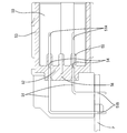
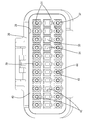
- Sectional drawing which shows the state which is the waterproof connector in Example 1, Comprising: The female connector and the male connector were fitted Sectional view showing male connector Sectional view showing female connector Rear view showing female connector with rear holder removed Partial enlarged view of a waterproof rubber stopper showing the shape of the lightening hole Rear view showing female connector with rear holder attached Sectional drawing which shows the female connector of the waterproof connector in Example 2 Rear view showing female connector with rear holder removed A partially enlarged view of a waterproof rubber stopper showing the shape of a lightening hole according to another embodiment (1)
- the lightening holes may be provided on both the front and rear sides of the closing wall, and the closing wall may be positioned substantially at the center in the front-rear direction of the waterproof rubber plug. According to such a configuration, the waterproof rubber stopper can be used even if it is reversed back and forth.
- the plurality of cavities are provided in three or more stages in the vertical direction, the empty cavity is arranged in the middle of the cavities, and the mating connector that can be fitted to the housing is
- the mating connector is provided with a plurality of mating terminal fittings divided into a plurality of stages in the vertical direction except for the position corresponding to the empty cavity, and the mating connector is mounted on the mating connector.
- the connection portion of the side terminal fitting with the circuit board may be arranged side by side at each stage.
- the mating terminal fitting located in the middle stage is omitted, the mating terminal fitting is connected to the circuit board as compared with the case where the uppermost or lowermost mating terminal fitting is omitted. Since the interval between the portions is large, the connection posture of the mating connector with respect to the circuit board can be stabilized.
- the through seal hole and the cutout hole may have different shapes when viewed from the rear. According to such a configuration, the through seal hole and the lightening hole can be distinguished from each other, so that it is possible to prevent the terminal fitting from being erroneously inserted into the lightening hole.
- the waterproof connector of the present invention has a rear holder attached to the rear side of the waterproof rubber stopper, and the terminal fitting can be introduced forward in a position corresponding to the cavity including the empty cavity.
- Terminal openings may be provided, and projections that fit into the empty cavities and the terminal inlets may be provided at positions corresponding to the closing walls on the front and rear surfaces of the waterproof rubber plug. .
- the front protrusion fits into the empty cavity of the housing, and the rear protrusion fits into the terminal introduction port of the rear holder, so that the through seal hole extends from the cavity and the terminal introduction port. It is possible to suppress displacement.
- the through seal hole may be provided with a lip portion that is in close contact with the outer peripheral surface of the electric wire, and the closing wall may be provided in accordance with the position of the lip portion. . According to such a configuration, it is possible to restrict the lip portion of the through seal hole adjacent to the closing wall from escaping to the lightening hole, so that the sealing performance can be improved.
- the waterproof connector C according to the present embodiment can be fitted to the female housing 20 in which a female terminal fitting (hereinafter referred to as a female terminal fitting 10) fixed to the terminal portion of the electric wire W is accommodated. And a male housing (mating housing) 50 attached to the circuit board P.
- the male housing 50 holds a plurality of tab-shaped male terminal fittings (hereinafter referred to as male terminal fittings 51).
- male terminal fittings 51 the fitting surface side in each of the housings 20 and 50 will be referred to as the front, and the upper side in FIG.
- the male housing 50 is made of synthetic resin, and as shown in FIG. 2, a terminal holding portion 52 for holding the male terminal fitting 51 and a front portion of the terminal holding portion 52 so that the female housing 20 can be fitted. And a hood portion 53 having a rectangular tube shape.
- a plurality of terminal attachment holes 54 penetrating in the front-rear direction are formed in the terminal holding portion 52.
- the plurality of terminal mounting holes 54 are formed in the upper part and the lower part of the terminal holding part 52 except for positions corresponding to empty cavities 21 ⁇ / b> V described later.
- Each terminal mounting hole 54 is formed through the center (axial center) of a columnar convex portion 55 that protrudes individually on the front surface of the terminal holding portion 52 (the back surface of the hood portion 53). Further, the portion corresponding to the empty cavity 21 ⁇ / b> V in the terminal holding portion 52 is closed by the closing portion 56.
- the male terminal fitting 51 is bent so as to form an L shape.
- One end of the male terminal fitting 51 is connected to the female terminal fitting 10 and the other end is connected to the circuit board P. It is said that.
- the male terminal fitting 51 is held in two steps at the upper and lower portions of the terminal holding portion 52, and the connecting portion 51A with the female terminal fitting 10 and the connecting portion 51B with the circuit board P are arranged in the horizontal direction at each step. They are arranged in a line.
- a relatively large space is provided in the front-rear direction between the connection portion 51B of the upper male terminal fitting 51 with the circuit board P and the connection portion 51B of the lower male terminal fitting 51 with the circuit board P. .
- This interval is set so that the male terminal fitting in the middle stage can be connected to the circuit board P if the male terminal fitting is provided in the middle stage.
- the female terminal fitting 10 is formed by pressing a conductive metal plate, a box-shaped connecting portion 11 to which the male terminal fitting 51 is connected is formed on the front end side, and the electric wire W is formed on the rear end side.
- a barrel portion 12 fixed to the terminal is formed (see FIG. 1).
- the connection portion 11 is provided with a locking projection 13 that can lock a lance 22 formed in the cavity 21.
- the female housing 20 is formed in a block shape as a whole from a synthetic resin material, and a plurality of cavities 21 extending in the front-rear direction are formed side by side in the width direction and the vertical direction. Specifically, in this embodiment, the cavities 21 are arranged in a line in the width direction of the female housing 20 and are provided in three stages in the vertical direction. And the cavity 21 arrange
- the female terminal fitting 10 can be inserted into each cavity 21 from behind.
- Each cavity 21 is provided with a lance 22 capable of locking the female terminal fitting 10 inserted at a regular position.
- a front seal member 23 is mounted on the front surface of the female housing 20.
- the front seal member 23 has a shape that covers substantially the entire front surface of the female housing 20, and is formed with a fitting hole 24 through which the columnar convex portion 55 of the male housing 50 can be fitted from the front.
- the fitting hole portion 24 is provided with a fitting lip portion 25, which is in close contact with the outer peripheral surface of the fitted columnar convex portion 55 and seals its periphery.
- a front holder 26 is attached to the front side of the front seal member 23.
- the front holder 26 covers substantially the entire front side of the front seal member 23, and has an insertion hole 27 through which the male terminal fitting 51 and the columnar convex portion 55 are inserted from the front.
- a housing recess 28 in which the waterproof rubber stopper 30 and the rear holder 40 are housed is provided on the rear side of the cavity 21 in the female housing 20.
- the housing recess 28 is sized to communicate with the inlets of all the cavities 21 and is provided to open rearward.
- the waterproof rubber plug 30 is formed in a thick plate shape that can be tightly fitted into the housing recess 28 of the female housing 20.
- a through-seal hole 31 is formed at a position corresponding to each cavity 21 except for the empty cavity 21V in the waterproof rubber plug 30 so as to be able to adhere to the outer peripheral surface of the electric wire W in a liquid-tight manner.
- the through seal hole 31 has a substantially circular shape and penetrates the waterproof rubber plug 30 in the front-rear direction.
- Three inner peripheral lip portions 32 are provided around the peripheral surface of each through seal hole 31. When the inner peripheral lip portion 32 is elastically brought into close contact with the outer peripheral surface of the electric wire W, each through seal hole 31 is closed.
- a position corresponding to the empty cavity 21 ⁇ / b> V is provided with a closing wall 33 and a lightening hole 34 extending from the closing wall 33 to the front side and the rear side.
- the closing wall 33 and the lightening hole 34 will be described in detail later.
- the outer peripheral surface of the waterproof rubber plug 30 is provided with three outer peripheral lip portions 35 that can elastically contact the inner peripheral wall of the housing recess 28.
- the outer peripheral lip portion 35 of the waterproof rubber plug 30 elastically contacts the inner peripheral wall of the accommodating recess 28, thereby The space is sealed in a liquid-tight state.
- the front and rear surfaces of the waterproof rubber plug 30 are substantially flat surfaces with no irregularities except for the through seal hole 31 and the lightening hole 34.
- the rear holder 40 is housed behind the waterproof rubber plug 30 in the housing recess 28 of the female housing 20, and pushes the waterproof rubber plug 30 forward and prevents the waterproof rubber plug 30 from being detached from the housing recess 28.
- the rear holder 40 is made of synthetic resin and has a thickness dimension (dimension in the front-rear direction) equivalent to that of the waterproof rubber plug 30.
- On the outer peripheral surface of the rear holder 40 there are provided a plurality of locking portions 41 that are locked to locked portions 29 provided on the female housing 20 to prevent the rear holder 40 from being detached.
- the locked portion 29 is an opening provided in the receiving recess 28 of the female housing 20, and the locking portion 41 is a protrusion protruding from the outer peripheral surface of the rear holder 40.
- a portion corresponding to all the cavities 21 including the empty cavities 21V is provided with a terminal introduction port 42 through which the female terminal fitting 10 can be introduced forward.
- the terminal introduction ports 42 are provided in the rear holder 40 in three stages.
- Each terminal introduction port 42 has a rectangular shape substantially the same size as the rear end opening of the cavity 21 and penetrates the rear holder 40 in the front-rear direction.
- a first concave groove 43 is formed on the lower surface of each terminal introduction port 42 across the front and rear to allow the locking projection 13 provided on the female terminal fitting 10 to pass forward.
- a second concave groove 44 shallower than the first concave groove 43 is formed in the front-rear direction.
- the closing wall 33 provided at a position corresponding to the empty cavity 21 ⁇ / b> V in the waterproof rubber plug 30 is positioned substantially at the center in the front-rear direction of the waterproof rubber plug 30.
- the closing wall 33 is provided in accordance with the position of the inner peripheral lip portion 32 located at the center in the front-rear direction among the three inner peripheral lip portions 32 provided in the through seal hole 31.
- the closing wall 33 has a thickness (dimension in the front-rear direction) that cannot be broken even if the terminal fitting is inadvertently thrust into the rearward hole 34.
- the thickness dimension of the closing wall 33 is a dimension equivalent to the dimension in the front-rear direction of the inner peripheral lip portion 32.
- a lightening hole 34 On the front and rear sides of the closing wall 33, there are provided a lightening hole 34.
- the front and rear thinning holes 34 are coaxial and formed in the same shape.
- the shape of the lightening hole 34 as viewed from the rear is a rectangular shape having a size that is slightly larger in the vertical direction than in the horizontal direction, and is different from the through seal hole 31. Since the lightening hole 34 is slightly smaller than the terminal introduction port 42 of the rear holder 40, the entire shape can be seen from the rear with the rear holder 40 attached.
- angular part of the lightening hole 34 is made into the round part 34A.
- the waterproof rubber plug 30 is fitted into the housing recess 28 of the female housing 20, and then the rear holder 40 is fitted into the housing recess 28. Then, the locking portion 41 of the rear holder 40 is fitted and locked to the locked portion 29 of the female housing 20, and the rear holder 40 is fixed to the female housing 20.
- the female terminal fitting 10 fixed to the terminal portion of the electric wire W is inserted forward from the terminal introduction port 42 of the rear holder 40.
- the through seal hole 31 and the lightening hole 34 can be visually observed through the terminal introduction port 42 of the rear holder 40, it is possible to prevent the female terminal fitting 10 from being erroneously inserted into the lightening hole 34. it can.
- the periphery of the through-seal hole 31 is pushed by the female terminal fitting 10, escapes to the lightening hole 34, and the through-seal hole 31 is pushed wide. . Then, the female terminal fitting 10 comes out forward of the through seal hole 31, is accommodated in the cavity 21 of the female housing 20, and is locked to the lance 22. Further, the through seal hole 31 is closed in a liquid-tight manner by the electric wire W. Thus, the assembly operation of the female housing 20 is completed.
- the female housing 20 of the waterproof connector C of the present embodiment has a plurality of cavities 21 into which the female terminal fittings 10 fixed to the terminal portions of the electric wires W can be inserted from the rear, and some of them are female terminal fittings 10.
- the empty cavity 21V is not inserted.
- a waterproof rubber plug 30 is attached to the rear surface side of the female housing 20.
- a through seal hole 31 that can be adhered in a liquid-tight manner to the outer peripheral surface of the electric wire W is provided at a position corresponding to the cavity 21 into which the electric wire W is inserted.
- the corresponding position is provided with a closing wall 33 and a lightening hole 34 extending from the closing wall 33 to the front side and the rear side.
- the portion corresponding to the empty cavity 21V of the waterproof rubber plug 30 is closed by the closing wall 33, there is no need to insert a dummy plug, so that the manufacturing cost increases even if the number of empty cavities 21V increases. Can be suppressed. Further, since the lightening holes 34 are provided in front and rear of the closing wall 33, when the female terminal fitting 10 is inserted into the cavity 21, the periphery of the through seal hole 31 escapes toward the lightening hole 34, and the through seal Since the hole 31 is widened, the operation of inserting the female terminal fitting 10 can be easily performed.
- the lightening holes 34 are provided on both front and rear sides of the closing wall 33, and the closing wall 33 is located at a substantially central portion in the front and rear direction of the waterproof rubber plug 30. According to this configuration, the waterproof rubber plug 30 can be used even if it is inverted back and forth.
- a plurality of cavities 21 are provided in three stages in the vertical direction, an empty cavity 21V is arranged in the middle of the cavities 21, and a male housing 50 that can be fitted to the female housing 20 is attached to the circuit board P.
- the male housing 50 is provided with the male terminal fitting 51 in two stages in the vertical direction except for the position corresponding to the empty cavity 21V, and the connection portion 51B of the male terminal fitting 51 to the circuit board P is provided. It is arranged for each stage.
- the connecting portion 51B of the male terminal fitting 51 to the circuit board P can be compared with the case where the uppermost or lowermost male terminal fitting 51 is omitted. Since the interval greatly increases in the front-rear direction, the connection posture of the male housing 50 with respect to the circuit board P can be stabilized.
- the through-seal hole 31 and the lightening hole 34 have different shapes when viewed from the rear. According to this configuration, since the through seal hole 31 and the lightening hole 34 can be distinguished from each other, it is possible to prevent the terminal fitting from being erroneously inserted into the lightening hole 34.
- an inner peripheral lip portion 32 that is in close contact with the outer peripheral surface of the electric wire W is provided in the through seal hole 31, and a closing wall 33 is provided in accordance with the position of the inner peripheral lip portion 32. According to this structure, since it can restrict
- Example 2 a waterproof connector C according to a second embodiment embodying the present invention will be described with reference to FIGS.
- the waterproof connector C of the present embodiment is implemented in that protrusions 60 that fit into the empty cavities 21V and the terminal inlets 42 are provided at positions corresponding to the front and rear closing walls 33 of the waterproof rubber plug 30, respectively. This is different from Example 1.
- symbol is attached
- the plurality of cavities 21 into which the female terminal fittings 10 fixed to the terminal portions of the electric wires W are inserted from the rear are arranged in three stages in the vertical direction.
- the cavities 21 that are provided separately and are located in the middle of these are vacant cavities 21V.
- a waterproof rubber plug 30 is mounted on the rear surface side of the female housing 20 as in the first embodiment.
- the waterproof rubber plug 30 has a through seal hole at a position corresponding to the cavity 21 into which the female terminal fitting 10 is inserted. 31 is provided, and a closing wall 33 is provided at a position corresponding to the empty cavity 21V.
- the closing wall 33 is located at a substantially central portion in the front-rear direction of the waterproof rubber plug 30, and the lightening holes 34 are provided on both front and rear sides of the closing wall 33. Further, the through-seal hole 31 and the lightening hole 34 have different shapes as seen from the rear as in the first embodiment.
- a rear holder 40 is attached to the rear side of the waterproof rubber plug 30 in the same manner as in the first embodiment.
- a terminal introduction port through which the female terminal fitting 10 can be introduced forward is provided at a position corresponding to all the cavities 21 of the rear holder 40. 42 is provided.
- the male housing 50 that can be fitted to the female housing 20 is attached to the circuit board P as in the first embodiment.
- the male housing 50 includes a plurality of male terminal fittings 51 and the female terminal fitting 10.
- the upper part and the lower part are provided in two stages, and the connection part 51B with the circuit board P is arranged for each stage.
- protrusions 60 that fit into the empty cavity 21V and the terminal introduction port 42, respectively.
- the protrusion 60 has a block shape that can be fitted to the rear end portion of the empty cavity 21V and the front end portion of the terminal introduction port 42.
- the protrusion 60 provided on the front surface side of the waterproof rubber plug 30 and the protrusion 60 provided on the rear surface side have substantially the same shape.
- each projection 60 When each projection 60 is viewed from the rear, as shown in FIG. 8, it has a rectangular shape whose dimension in the vertical direction is slightly larger than that in the horizontal direction.
- the lightening hole 34 is formed at the center of the protrusion 60.
- the lightening hole 34 When the lightening hole 34 is viewed from the rear, as shown in FIG. 8, it has a substantially rectangular shape with the entire circumference being slightly larger in the horizontal direction than in the vertical direction.
- the closing wall 33 is provided at a position corresponding to the empty cavity 21V of the waterproof rubber plug 30, and the lightening holes 34 are provided in front and rear of the closing wall 33. Since it is formed, it is not necessary to insert a dummy plug into the empty cavity 21V, so that it is possible to suppress an increase in manufacturing cost even if the number of empty cavities 21V is increased. When inserted into 20, the periphery of the through-seal hole 31 escapes to the side of the lightening hole 34 and the through-seal hole 31 widens, so that the work of inserting the female terminal fitting 10 can be easily performed.
- the protrusions 60 that fit into the empty cavities 21V and the terminal introduction ports 42 are provided at positions corresponding to the front and rear closing walls 33 of the waterproof rubber plug 30, the waterproof rubber plug 30 is thereby positioned. Further, it is possible to prevent the through seal hole 31 from being displaced from the cavity 21 and the terminal introduction port 42.
- the present invention is not limited to the embodiments described with reference to the above description and drawings.
- the following embodiments are also included in the technical scope of the present invention.
- the lightening hole 34 is substantially rectangular, but the shape is not limited to this, and the shape of the lightening hole 34 may be arbitrarily changed.
- the hole 70 may be formed in a diamond shape as a whole and rounded at the upper, lower, left and right corners.
- the front and rear thinning holes 34 are coaxially formed in the same shape.
- the present invention is not limited to this, and the front and rear thinning holes are not necessarily formed coaxially and in the same shape.
- the closing wall 33 is provided at the central portion of the waterproof rubber plug 30.
- the present invention is not limited thereto, and for example, the closing wall may be provided at the front end portion or the rear end portion of the waterproof rubber plug.
- the through seal hole 31 and the lightening hole 34 have different shapes.
- the present invention is not limited to this, and the through seal hole and the lightening hole may have substantially the same shape. Different sizes may be made distinguishable.
- the present invention is applied to the female housing 20 in which the cavity 21 is provided in 11 chambers in the width direction and in three stages in the vertical direction has been described.
- the present invention can be applied to a housing in which cavities are arranged in only one stage, two stages, or four or more stages, and can be applied to any number of cavities in each stage. be able to.
- the rear holder 40 is fitted into the receiving recess 28, but the present invention is not limited to this.
- the rear holder has a cap shape and is mounted on the rear end of the housing. It may be.
- all cavities 21 arranged in the middle stage among the plurality of cavities 21 are vacant cavities 21V.
- the present invention is not limited to this, and cavities in other stages may be vacant cavities. Alternatively, only a part of the middle cavities may be vacant cavities.
- the male housing 50 is attached to the circuit board P.
- the present invention is not limited to this.
- a male terminal fitting fixed to the terminal portion of the electric wire is inserted into the male housing. And may be accommodated.
- the male terminal fitting 51 is bent so as to form an L shape.
- the present invention is not limited to this.
- the male terminal fitting may be linear.
Landscapes
- Connector Housings Or Holding Contact Members (AREA)
Abstract
L'invention concerne un connecteur étanche à l'eau, dont le coût de fabrication n'augmente pas même si le nombre de cavités vides augmente. Un connecteur étanche à l'eau est pourvu : d'un boîtier (20) ayant une pluralité de cavités (21) dans lesquelles des accessoires de borne (10) fixés aux extrémités de fils électriques (W) peuvent être insérés à partir de derrière, une partie de la pluralité de cavités (21) étant des cavités vides (21V) dans lesquelles les accessoires de borne (10) ne sont pas insérés ; et d'un bouchon (30) en caoutchouc étanche à l'eau monté sur le côté face arrière du boîtier (20). Le bouchon (30) en caoutchouc étanche à l'eau présente, au niveau des positions de celui-ci correspondant aux cavités (21) dans lesquelles les accessoires de borne (10) sont insérés, des trous traversants (31) d'étanchéité capables de venir étroitement en contact liquide étanche avec les surfaces périphériques externes des fils électriques (W). Le bouchon (30) en caoutchouc étanche à l'eau présente en outre, au niveau des positions de celui-ci correspondant aux cavités vides (21V), des parois de fermeture (33) et des trous d'allègement (34), les trous d'allègement (34) s'étendant des parois de fermeture (33) jusqu'au côté face avant ou face arrière.
Applications Claiming Priority (2)
| Application Number | Priority Date | Filing Date | Title |
|---|---|---|---|
| JP2015016570A JP2016143478A (ja) | 2015-01-30 | 2015-01-30 | 防水コネクタ |
| JP2015-016570 | 2015-01-30 |
Publications (1)
| Publication Number | Publication Date |
|---|---|
| WO2016121476A1 true WO2016121476A1 (fr) | 2016-08-04 |
Family
ID=56543096
Family Applications (1)
| Application Number | Title | Priority Date | Filing Date |
|---|---|---|---|
| PCT/JP2016/050616 Ceased WO2016121476A1 (fr) | 2015-01-30 | 2016-01-12 | Connecteur étanche à l'eau |
Country Status (2)
| Country | Link |
|---|---|
| JP (1) | JP2016143478A (fr) |
| WO (1) | WO2016121476A1 (fr) |
Families Citing this family (1)
| Publication number | Priority date | Publication date | Assignee | Title |
|---|---|---|---|---|
| JP6512076B2 (ja) * | 2015-11-18 | 2019-05-15 | 住友電装株式会社 | 弾性部材および防水コネクタ |
Citations (11)
| Publication number | Priority date | Publication date | Assignee | Title |
|---|---|---|---|---|
| JPH0476269U (fr) * | 1990-11-15 | 1992-07-03 | ||
| JPH0765894A (ja) * | 1993-08-26 | 1995-03-10 | Sumitomo Wiring Syst Ltd | コネクタ |
| JPH07230845A (ja) * | 1994-02-16 | 1995-08-29 | Sumitomo Wiring Syst Ltd | 多極コネクタの端子の誤挿入防止構造 |
| JP2001006799A (ja) * | 1999-06-23 | 2001-01-12 | Sumitomo Wiring Syst Ltd | 防水コネクタ |
| JP2002246107A (ja) * | 2001-02-16 | 2002-08-30 | Sumitomo Wiring Syst Ltd | コネクタ |
| JP2004071200A (ja) * | 2002-08-02 | 2004-03-04 | Sumitomo Wiring Syst Ltd | 防水コネクタ |
| JP2007005018A (ja) * | 2005-06-21 | 2007-01-11 | Tokai Rika Co Ltd | 防水型コネクタ |
| WO2008107740A1 (fr) * | 2007-03-06 | 2008-09-12 | Fci | Joint d'étanchéité pour connecteur électrique |
| JP2008300318A (ja) * | 2007-06-04 | 2008-12-11 | Sumitomo Wiring Syst Ltd | コネクタ |
| JP2009266793A (ja) * | 2008-04-03 | 2009-11-12 | Yazaki Corp | コネクタ用パッキン構造 |
| JP2013033633A (ja) * | 2011-08-02 | 2013-02-14 | Sumitomo Wiring Syst Ltd | コネクタ |
-
2015
- 2015-01-30 JP JP2015016570A patent/JP2016143478A/ja active Pending
-
2016
- 2016-01-12 WO PCT/JP2016/050616 patent/WO2016121476A1/fr not_active Ceased
Patent Citations (11)
| Publication number | Priority date | Publication date | Assignee | Title |
|---|---|---|---|---|
| JPH0476269U (fr) * | 1990-11-15 | 1992-07-03 | ||
| JPH0765894A (ja) * | 1993-08-26 | 1995-03-10 | Sumitomo Wiring Syst Ltd | コネクタ |
| JPH07230845A (ja) * | 1994-02-16 | 1995-08-29 | Sumitomo Wiring Syst Ltd | 多極コネクタの端子の誤挿入防止構造 |
| JP2001006799A (ja) * | 1999-06-23 | 2001-01-12 | Sumitomo Wiring Syst Ltd | 防水コネクタ |
| JP2002246107A (ja) * | 2001-02-16 | 2002-08-30 | Sumitomo Wiring Syst Ltd | コネクタ |
| JP2004071200A (ja) * | 2002-08-02 | 2004-03-04 | Sumitomo Wiring Syst Ltd | 防水コネクタ |
| JP2007005018A (ja) * | 2005-06-21 | 2007-01-11 | Tokai Rika Co Ltd | 防水型コネクタ |
| WO2008107740A1 (fr) * | 2007-03-06 | 2008-09-12 | Fci | Joint d'étanchéité pour connecteur électrique |
| JP2008300318A (ja) * | 2007-06-04 | 2008-12-11 | Sumitomo Wiring Syst Ltd | コネクタ |
| JP2009266793A (ja) * | 2008-04-03 | 2009-11-12 | Yazaki Corp | コネクタ用パッキン構造 |
| JP2013033633A (ja) * | 2011-08-02 | 2013-02-14 | Sumitomo Wiring Syst Ltd | コネクタ |
Also Published As
| Publication number | Publication date |
|---|---|
| JP2016143478A (ja) | 2016-08-08 |
Similar Documents
| Publication | Publication Date | Title |
|---|---|---|
| JP6143183B2 (ja) | フェライトコア内蔵防水コネクタ | |
| JP6368504B2 (ja) | 電気コネクタ | |
| JP5417954B2 (ja) | 防水コネクタ | |
| US9948023B2 (en) | Connector | |
| JP5835434B1 (ja) | 防水コネクタ | |
| US10644430B2 (en) | Connector and connector structure | |
| US10910761B2 (en) | Connector having a ferrite and a sealing member | |
| CN109004430B (zh) | 连接器 | |
| TW201539874A (zh) | 電纜線連接器及其連接器總成 | |
| CN101176239A (zh) | 用于电连接器的改进环式接头及包括该接头的电连接器 | |
| US9991634B2 (en) | Connector | |
| JP6024611B2 (ja) | コネクタ | |
| JP6512076B2 (ja) | 弾性部材および防水コネクタ | |
| US10008803B2 (en) | Connector for a camera with reduced dimensions in a fitting direction | |
| JP5573718B2 (ja) | 防水コネクタ | |
| JP2016143478A (ja) | 防水コネクタ | |
| JP6015628B2 (ja) | コネクタ | |
| JP5524789B2 (ja) | コネクタ | |
| JP5687461B2 (ja) | コネクタ | |
| TWI573343B (zh) | Waterproof connector | |
| JP6225140B2 (ja) | 防水コネクタのマットシールカバー | |
| JP2017010625A (ja) | コネクタ装置 | |
| JP2015099720A (ja) | 防水コネクタ用の一括ゴム栓 |
Legal Events
| Date | Code | Title | Description |
|---|---|---|---|
| 121 | Ep: the epo has been informed by wipo that ep was designated in this application |
Ref document number: 16743080 Country of ref document: EP Kind code of ref document: A1 |
|
| NENP | Non-entry into the national phase |
Ref country code: DE |
|
| 122 | Ep: pct application non-entry in european phase |
Ref document number: 16743080 Country of ref document: EP Kind code of ref document: A1 |