WO2016121623A1 - Dispositif de climatisation - Google Patents
Dispositif de climatisation Download PDFInfo
- Publication number
- WO2016121623A1 WO2016121623A1 PCT/JP2016/051743 JP2016051743W WO2016121623A1 WO 2016121623 A1 WO2016121623 A1 WO 2016121623A1 JP 2016051743 W JP2016051743 W JP 2016051743W WO 2016121623 A1 WO2016121623 A1 WO 2016121623A1
- Authority
- WO
- WIPO (PCT)
- Prior art keywords
- heat exchanger
- refrigerant
- indoor heat
- indoor
- temperature sensor
- Prior art date
- Legal status (The legal status is an assumption and is not a legal conclusion. Google has not performed a legal analysis and makes no representation as to the accuracy of the status listed.)
- Ceased
Links
Images




Classifications
-
- F—MECHANICAL ENGINEERING; LIGHTING; HEATING; WEAPONS; BLASTING
- F25—REFRIGERATION OR COOLING; COMBINED HEATING AND REFRIGERATION SYSTEMS; HEAT PUMP SYSTEMS; MANUFACTURE OR STORAGE OF ICE; LIQUEFACTION SOLIDIFICATION OF GASES
- F25B—REFRIGERATION MACHINES, PLANTS OR SYSTEMS; COMBINED HEATING AND REFRIGERATION SYSTEMS; HEAT PUMP SYSTEMS
- F25B49/00—Arrangement or mounting of control or safety devices
-
- F—MECHANICAL ENGINEERING; LIGHTING; HEATING; WEAPONS; BLASTING
- F24—HEATING; RANGES; VENTILATING
- F24F—AIR-CONDITIONING; AIR-HUMIDIFICATION; VENTILATION; USE OF AIR CURRENTS FOR SCREENING
- F24F11/00—Control or safety arrangements
- F24F11/89—Arrangement or mounting of control or safety devices
-
- F—MECHANICAL ENGINEERING; LIGHTING; HEATING; WEAPONS; BLASTING
- F25—REFRIGERATION OR COOLING; COMBINED HEATING AND REFRIGERATION SYSTEMS; HEAT PUMP SYSTEMS; MANUFACTURE OR STORAGE OF ICE; LIQUEFACTION SOLIDIFICATION OF GASES
- F25B—REFRIGERATION MACHINES, PLANTS OR SYSTEMS; COMBINED HEATING AND REFRIGERATION SYSTEMS; HEAT PUMP SYSTEMS
- F25B13/00—Compression machines, plants or systems, with reversible cycle
-
- F—MECHANICAL ENGINEERING; LIGHTING; HEATING; WEAPONS; BLASTING
- F25—REFRIGERATION OR COOLING; COMBINED HEATING AND REFRIGERATION SYSTEMS; HEAT PUMP SYSTEMS; MANUFACTURE OR STORAGE OF ICE; LIQUEFACTION SOLIDIFICATION OF GASES
- F25B—REFRIGERATION MACHINES, PLANTS OR SYSTEMS; COMBINED HEATING AND REFRIGERATION SYSTEMS; HEAT PUMP SYSTEMS
- F25B2313/00—Compression machines, plants or systems with reversible cycle not otherwise provided for
- F25B2313/031—Sensor arrangements
- F25B2313/0314—Temperature sensors near the indoor heat exchanger
Definitions
- the present invention relates to an air conditioner, and more particularly to an air conditioner that performs a heating operation by causing an indoor heat exchanger to function as a refrigerant radiator.
- the attachment position of the thermistor attached to the indoor heat exchanger is close to the side when the front panel of the indoor unit is opened from the viewpoint of the harness length and maintainability of the electrical components. Is attached to the lower stage of the heat exchanger.
- the portion corresponding to the thermistor attachment position also becomes a liquid pool state, Even if the control is performed by opening the electric expansion valve, it is not solved, and an accurate saturation temperature cannot be detected due to the influence of the liquid pool. As a result, the subcool control is hindered and the high pressure is detected at a low level, which is not preferable in terms of safety.
- An object of the present invention is to correctly detect a saturation temperature even when a liquid pool is generated in an operation state in a low circulation amount region in an air conditioner that performs a heating operation by causing an indoor heat exchanger to function as a refrigerant radiator.
- An object of the present invention is to provide an air conditioner that can be used.
- An air conditioner is an air conditioner that performs a heating operation by causing an indoor heat exchanger to function as a refrigerant radiator, and includes a shunt and a temperature sensor.
- the shunt has a shunt body and a plurality of shunt tubes.
- the shunt body is arranged in the vicinity of the refrigerant outlet of the indoor heat exchanger that functions as a radiator.
- the shunt pipe branches from the shunt main body into a plurality of paths formed in the indoor heat exchanger.
- the temperature sensor detects the saturation temperature of the refrigerant flowing through the indoor heat exchanger.
- the temperature sensor is attached above the center in the height direction of the indoor heat exchanger in use or above the shunt body.
- liquid pools are less likely to occur in the refrigerant path higher than the shunt body, and liquid pools are lower in the refrigerant path lower than the shunt body. Is likely to occur. This is considered to be caused by the fact that the amount of refrigerant circulation is reduced, so that the liquid in the refrigerant path at a position lower than the flow divider main body cannot be lifted up to the flow divider main body due to the influence of gravity.
- the air conditioner is above the center in the height direction of the indoor heat exchanger or is divided. Since no liquid pool is generated above the vessel, a temperature sensor attached to that region can detect an accurate saturation temperature.
- An air conditioner according to a second aspect of the present invention is the air conditioner according to the first aspect, wherein the temperature sensor counts 30% of the total number of paths counted from the uppermost path among a plurality of paths. It is attached to the path that occupies the area. In this air conditioner, an accurate saturation temperature can be detected more reliably.
- the air conditioner according to a third aspect of the present invention is the air conditioner according to the second aspect, wherein the temperature sensor is attached to a path located at the uppermost stage among a plurality of paths. In this air conditioner, an accurate saturation temperature can be detected more reliably.
- An air conditioner according to a fourth aspect of the present invention is the air conditioner according to any one of the first aspect to the fourth aspect, wherein the temperature sensor is in a specific path to which the temperature sensor is attached among a plurality of paths. Is attached to a portion near the gas side end with respect to the flow of the refrigerant flowing through the specific path.
- the temperature sensor is attached to the part near the gas side, avoiding the part close to the liquid, with respect to the flow of the refrigerant flowing through the path. It is avoided that it cannot be detected.
- An air conditioner according to a fifth aspect of the present invention is the air conditioner according to any one of the first aspect to the fourth aspect, and is operated continuously for 30 seconds or more at a capacity lower than 45% of the rated capacity.
- the minimum heating operation state can be naturally obtained if the compressor range is set so that the minimum heating operation state can be made to appear and is operated according to the load.
- the refrigerant circulation amount is reduced by operating at a low compressor rotation speed that produces the minimum heating capacity, it is more than the center in the height direction of the indoor heat exchanger. Since no liquid pool is generated on the upper side or on the upper side of the shunt, a temperature sensor attached to the region can detect an accurate saturation temperature. As a result, the possibility of hindering the subcool control is also eliminated, and it is not necessary to control the motor-operated valve opening operation only for eliminating the liquid pool as in the prior art, and naturally it is not necessary to provide a pressure sensor.
- the temperature sensor is attached to a path that occupies 30% of the total number of paths counting from the path located at the top of the plurality of paths. Furthermore, an accurate saturation temperature can be detected with certainty.
- the temperature sensor is attached to the uppermost path among the plurality of paths, so that it is possible to more accurately detect the saturation temperature.
- the temperature sensor is attached to the portion near the gas side while avoiding the portion close to the liquid with respect to the flow of the refrigerant flowing through the path. It is avoided that the saturation temperature cannot be detected when the light is on.
- the compressor range is set so that the minimum heating operation state can be caused by appearance, the minimum heating will naturally occur if the compressor is operated according to the load.
- the driving state can be output.
- the piping system figure which shows the structure of the refrigerant circuit of the air conditioning apparatus which concerns on one Embodiment of this invention.
- the top view which looked at the inside of the indoor unit of an air conditioning apparatus from the top
- Schematic shows the positional relationship of a shunt with respect to the height direction of the indoor heat exchanger in use condition.
- the graph which shows the temperature distribution in the indoor heat exchanger at the time of heating minimum capacity operation.
- FIG. 1 is a piping system diagram showing a configuration of a refrigerant circuit C of an air conditioner 10 according to an embodiment of the present invention.
- an air conditioner 10 performs indoor cooling and heating.
- the air conditioning apparatus 10 includes an outdoor unit 11 installed outside and an indoor unit 20 installed indoors.
- the outdoor unit 11 and the indoor unit 20 are connected to each other by two connecting pipes 2 and 3.
- the refrigerant circuit C is comprised.
- a vapor compression refrigeration cycle is performed by circulating the filled refrigerant.
- Outdoor unit 11 The outdoor unit 11 is provided with a compressor 12, an outdoor heat exchanger 13, an outdoor expansion valve 14, and a four-way switching valve 15.
- Compressor 12 The compressor 12 compresses the low-pressure refrigerant and discharges the compressed high-pressure refrigerant.
- a scroll type or rotary type compression mechanism is driven by the compressor motor 12a.
- the operation frequency of the compressor motor 12a is variable by an inverter device.
- Outdoor heat exchanger 13 is a fin-and-tube heat exchanger.
- An outdoor fan 16 is installed in the vicinity of the outdoor heat exchanger 13. In the outdoor heat exchanger 13, the air conveyed by the outdoor fan 16 and the refrigerant exchange heat.
- Outdoor expansion valve 14 is an electronic expansion valve with a variable opening.
- the outdoor expansion valve 14 is disposed downstream of the outdoor heat exchanger 13 in the refrigerant flow direction in the refrigerant circuit C during the cooling operation.
- the opening degree of the outdoor expansion valve 14 is fully open.
- the degree of opening of the outdoor expansion valve 14 is reduced to a pressure at which the refrigerant flowing into the outdoor heat exchanger 13 can be evaporated in the outdoor heat exchanger 13 (that is, evaporation pressure). Adjusted.
- the four-way switching valve 15 has first to fourth ports.
- the first port is connected to the discharge side of the compressor 12
- the second port is connected to the suction side of the compressor 12
- the third port is connected to the gas side end of the outdoor heat exchanger.
- the fourth port is connected to the gas-side shutoff valve 5.
- the four-way switching valve 15 switches between a first state (state indicated by a solid line in FIG. 1) and a second state (state indicated by a broken line in FIG. 1).
- first state state indicated by a solid line in FIG. 1
- second state state indicated by a broken line in FIG. 1
- the first port communicates with the third port
- the second port communicates with the fourth port
- the first port communicates with the fourth port
- the second port communicates with the third port.
- Outdoor fan 16 The outdoor fan 16 is configured by a propeller fan driven by an outdoor fan motor 16a.
- the outdoor fan motor 16a is configured to have a variable rotational speed by an inverter device.
- Liquid communication pipe 2 and gas communication pipe 3 The two communication pipes are constituted by a liquid communication pipe 2 and a gas communication pipe 3. One end of the liquid communication pipe 2 is connected to the liquid side closing valve 4, and the other end is connected to the liquid side end of the indoor heat exchanger 32. One end of the gas communication pipe 3 is connected to the gas side closing valve 5, and the other end is connected to the gas side end of the indoor heat exchanger 32.
- the indoor unit 20 is provided with an indoor heat exchanger 32, an indoor expansion valve 39, an indoor fan 27, and a refrigerant temperature sensor 183.
- the indoor heat exchanger 32 is a fin-and-tube heat exchanger.
- An indoor fan 27 is installed in the vicinity of the indoor heat exchanger 32.
- the indoor expansion valve 39 is connected to the liquid end side of the indoor heat exchanger 32 in the refrigerant circuit C.
- the indoor expansion valve 39 is composed of an electronic expansion valve whose opening degree is variable.
- the indoor fan 27 is a centrifugal blower driven by an indoor fan motor 27a.
- the indoor fan motor 27a is configured to have a variable rotational speed by an inverter device.
- (1-2-4) Refrigerant temperature sensor 183 The refrigerant temperature sensor 183 is attached to a predetermined position of the indoor heat exchanger 32, and detects the temperature of the refrigerant in the gas-liquid two-phase state flowing through the indoor heat exchanger 32. In the air conditioner 10, the cooling capacity and the heating capacity are adjusted based on the temperature detected by the refrigerant temperature sensor 183.
- Control unit 800 includes an outdoor side control unit 801 and an indoor side control unit 803.
- the outdoor side control part 801 is arrange
- the indoor side control unit 803 is disposed in the indoor unit 20 and obtains a saturation temperature from the detection value of the refrigerant temperature sensor 183 or executes the rotational speed control of the indoor fan 27.
- Each of the outdoor side control unit 801 and the indoor side control unit 803 has a microcomputer, a memory, and the like, and can exchange control signals and the like with each other.
- FIG. 2 is an external perspective view of the indoor unit 20 of the air conditioner 10.
- FIG. 3 is a longitudinal sectional view of the indoor unit 20 of the air conditioner 10.
- FIG. 4 is a plan view of the interior of the indoor unit 20 of the air conditioner 10 viewed from the top side.
- the indoor unit 20 of the present embodiment is configured to be embedded in a ceiling.
- the indoor unit 20 includes an indoor unit body 21 and a decorative panel 40 attached to the lower portion of the indoor unit body 21.
- (2-1) Indoor unit body 21 As shown in FIGS. 2 and 3, the indoor unit main body 21 includes a box-shaped casing 22 having a substantially rectangular parallelepiped shape.
- the side plate 24 of the casing 22 penetrates the liquid side connecting pipe 6 and the gas side connecting pipe 7 connected to the indoor heat exchanger 32 (see FIG. 4).
- the liquid connection pipe 6 is connected to the liquid side connection pipe 6, and the gas communication pipe 3 is connected to the gas side connection pipe 7.
- an indoor fan 27, a bell mouth 31, an indoor heat exchanger 32, and a drain pan 36 are accommodated inside the casing 22.
- the indoor fan 27 is disposed at the center inside the casing 22.
- the indoor fan 27 includes an indoor fan motor 27a and an impeller 30.
- the indoor fan motor 27 a is supported on the top plate of the casing 22.
- the impeller 30 is composed of a plurality of turbo blades 30a arranged along the rotation direction of the drive shaft 27b.
- the bell mouth 31 is disposed below the indoor fan 27.
- the bell mouth 31 has a circular opening at each of the upper end and the lower end, and is formed in a cylindrical shape whose opening area increases toward the decorative panel 40.
- the internal space of the bell mouth 31 communicates with the blade housing space of the indoor fan 27.
- the indoor heat exchanger 32 is provided with a heat transfer tube bent so as to surround the periphery of the indoor fan 27.
- the indoor heat exchanger 32 is installed on the upper surface of the drain pan 36 so as to stand upward. The air blown from the indoor fan 27 to the side passes through the indoor heat exchanger 32.
- the indoor heat exchanger 32 constitutes an evaporator that cools the air during the cooling operation, and constitutes a condenser (heat radiator) that heats the air during the heating operation.
- the decorative panel 40 is attached to the lower surface of the casing 22.
- the decorative panel 40 includes a panel body 41 and a suction grill 60.
- the panel body 41 is formed in a rectangular frame shape in plan view. In the panel main body 41, one panel side suction channel 42 and four panel side outlet channels 43 are formed.
- the panel side suction flow path 42 is formed at the center of the panel body 41.
- a suction port 42a facing the indoor space is formed at the lower end of the panel side suction flow channel 42. Also, inside the panel side suction flow channel 42, dust collection for capturing dust in the air sucked from the suction port 42a.
- a filter 45 is provided inside the panel side suction flow channel 42.
- Each panel side outlet channel 43 is formed outside the panel side inlet channel 42 so as to surround the periphery of the panel side inlet channel 42.
- Each panel-side outlet channel 43 extends along four sides of each panel-side suction channel 42. At the lower end of each panel-side outlet passage 43, an outlet 43a facing the indoor space is formed.
- the suction grill 60 is attached to the lower end of the panel side suction flow path 42 (that is, the suction port 42a).
- the high-pressure refrigerant compressed by the compressor 12 flows through the outdoor heat exchanger 13 and exchanges heat with outdoor air.
- the high-pressure refrigerant dissipates heat to the outdoor air and condenses.
- the refrigerant condensed in the outdoor heat exchanger 13 is sent to the indoor unit 20.
- the refrigerant flows through the indoor heat exchanger 32 after being decompressed by the indoor expansion valve 39.
- the indoor air sequentially flows upward through the internal space of the suction port 42 a, the panel side suction flow path 42, and the bell mouth 31, and is sucked into the blade accommodation space of the indoor fan 27.
- the air in the blade accommodating space is conveyed by the impeller 30 and blown out radially outward.
- This air passes through the indoor heat exchanger 32 and exchanges heat with the refrigerant.
- the refrigerant absorbs heat from the indoor air and evaporates, and the air is cooled by the refrigerant.
- the air cooled by the indoor heat exchanger 32 is diverted to each main body outlet channel 37, then flows downward through the panel outlet channel 43, and is supplied to the indoor space from the outlet 43a.
- the refrigerant evaporated in the indoor heat exchanger 32 is sucked into the compressor 12 and compressed again.
- the high-pressure refrigerant compressed by the compressor 12 flows through the indoor heat exchanger 32 of the indoor unit 20.
- room air sequentially flows upward through the internal space of the suction port 42 a, the panel side suction flow path 42, and the bell mouth 31, and is sucked into the blade accommodation space of the indoor fan 27.
- the air in the blade accommodating space is conveyed by the impeller 30 and blown out radially outward.
- This air passes through the indoor heat exchanger 32 and exchanges heat with the refrigerant.
- the refrigerant dissipates heat to the indoor air and condenses, and the air is heated by the refrigerant.
- the indoor heat exchanger 32 After the air heated by the indoor heat exchanger 32 is diverted to each main body outlet channel 37, it flows downward through the panel outlet channel 43 and is supplied to the indoor space from the outlet 43a.
- the refrigerant condensed in the indoor heat exchanger 32 flows through the outdoor heat exchanger 13 after being depressurized by the outdoor expansion valve 14. In the outdoor heat exchanger 13, the refrigerant absorbs heat from the outdoor air and evaporates. The refrigerant evaporated in the outdoor heat exchanger 13 is sucked into the compressor 12 and compressed again.
- the indoor heat exchanger 32 has a first side end 32a and a second side end 32b.
- the first side end portion 32a is formed at one side end in the longitudinal direction of the heat transfer tube of the indoor heat exchanger 32
- the second side end portion 32b is the other side end in the longitudinal direction of the heat transfer tube of the indoor heat exchanger 32. Is formed.
- the gas side pipe 70 and the liquid side pipe 80 are installed in the pipe housing space S between the first side end portion 32a and the second side end portion 32b of the indoor heat exchanger 32.
- FIG. 5 is a front view of the indoor heat exchanger 32 when the first side end portion 32a is the front surface. 4 and 5, the gas side pipe 70 is formed between the gas side end of the indoor heat exchanger 32 located at the first side end 32a and the gas side connecting pipe 7 described above.
- the gas side pipe 70 has a header 71 connected to the indoor heat exchanger 32 and a gas relay pipe 72 connected between the header 71 and the gas side connection pipe 7.
- the header 71 is disposed in the vicinity of the first side end 32 a of the indoor heat exchanger 32.
- the header 71 includes a header body 71a and a plurality of branch pipes 71b branched from the header body 71a.
- Header body 71a The header body 71a extends in the vertical direction so as to follow the first side end portion 32a of the indoor heat exchanger 32. That is, the header main body 71a is parallel to the first side end portion 32a so as to be spaced from the first side end portion 32a of the indoor heat exchanger 32 by a predetermined distance.
- the header body 71a joins the refrigerant that has flowed out of the branch pipes 71b during cooling. Further, the header main body 71a diverts the refrigerant flowing out from the gas relay pipe 72 to each branch pipe 71b during heating.
- Branch pipe 71b The plurality of branch pipes 71 b are disposed between the header main body 71 a and the first side end 32 a of the indoor heat exchanger 32.
- Each branch pipe 71b is arranged in a direction (vertical direction) along the side surface of the header body 71a so as to be parallel to each other.
- One end of each branch pipe 71b is connected to each heat transfer pipe (refrigerant path P) of the first side end 32a of the indoor heat exchanger 32.
- the other end of each branch pipe 71b is connected to the header body 71a and communicates with the inside of the header body 71a.
- the liquid side pipe 80 is formed between the liquid side end of the indoor heat exchanger 32 located at the second side end 32b and the liquid side connecting pipe 6 described above.
- the liquid side pipe 80 includes a flow divider 81 and a liquid relay pipe 82 connected between the flow divider 81 and the liquid side connection pipe 6.
- the flow divider 81 is disposed in the vicinity of the second side end 32 b of the indoor heat exchanger 32.
- the flow divider 81 includes a flow divider body 81a and a plurality of flow dividing pipes 81b branched from the flow distributor body 81a.
- the flow divider main body 81a is disposed in the pipe housing space S between the first side end 32a and the second side end 32b of the indoor heat exchanger 32.
- the flow divider main body 81a is formed in a bottomed cylindrical shape whose axis extends vertically, and a plurality of flow dividing pipes 81b are connected to the upper end surface thereof.
- FIG. 6 is a schematic diagram showing the positional relationship of the flow divider 81 with respect to the height direction of the indoor heat exchanger 32 in a use state.
- the flow divider main body 81 a has an upper portion (connection portion with the flow dividing pipe 81 b) whose height of the indoor heat exchanger 32 is higher than the height direction of the indoor heat exchanger 32 in the front view of FIG. 6. It is opposed to the second side end 32b of the indoor heat exchanger 32 with the connection with the flow dividing pipe 81b facing vertically upward above the center.
- the flow divider main body 81a diverts the refrigerant flowing out from the liquid relay pipe 82 to each of the diversion pipes 81b during cooling. Moreover, the flow divider main body 81a joins the refrigerant
- Shunt pipe 81b The plurality of flow dividing pipes 81 b are disposed between the flow divider main body 81 a and the second side end portion 32 b of the indoor heat exchanger 32.
- Each branch pipe 81b is configured by a capillary tube having a smaller flow path diameter than the flow distributor body 81a.
- the connecting portion between the flow divider main body 81 a and the flow dividing pipe 81 b is above the center of the height of the indoor heat exchanger 32, and in the present embodiment, the indoor heat exchanger 32 is taken as an example. Is set to a position slightly higher than the height position of the seventh heat transfer tube from above.
- the connecting portion between the flow divider main body 81a and the flow dividing pipe 81b is directed vertically upward, the flow dividing pipe 81b connected from the uppermost heat transfer pipe of the indoor heat exchanger 32 to each of the sixth stage heat transfer pipes, It exists in the position higher than the connection part of the flow divider main body 81a and the flow dividing pipe 81b.
- the branch pipe 81b connected from the seventh stage heat transfer pipe to the sixteenth stage heat transfer pipe of the indoor heat exchanger 32 is located at a position lower than the connection portion between the flow divider main body 81a and the branch pipe 81b.
- the liquid refrigerant flowing through the branch pipe 81b connected from the uppermost heat transfer tube of the indoor heat exchanger 32 to each of the sixth heat transfer tubes flows against the gravity, and the indoor heat exchanger
- the liquid refrigerant flowing through the diversion pipe 81b connected from the 32nd seventh stage heat transfer pipe to the 16th stage heat transfer pipe flows without resisting gravity.
- the liquid refrigerant flowing through the diverter pipe 81b connected from the uppermost heat transfer pipe of the indoor heat exchanger 32 to each of the sixth heat transfer pipes flows without resisting gravity.
- the liquid refrigerant flowing through the diversion pipe 81b connected from the seventh stage heat transfer pipe to the sixteenth stage heat transfer pipe of the vessel 32 flows against gravity.
- the liquid relay pipe 82 is connected to the flow distributor main body 81a and the liquid side via a curved relay portion 83 that extends vertically downward from the flow distributor main body 81a and then extends upward toward the liquid side connection pipe 6 and curves in a substantially U shape.
- the connecting pipe 6 is connected.
- the refrigerant temperature sensor 183 includes the first side end portion 32a of the indoor heat exchanger 32 or It is attached to any one of a plurality of U-shaped portions protruding laterally from the second side end portion 32b.
- FIG. 7 is a plan view of one heat transfer tube of the indoor heat exchanger 32. 6 and 7, the indoor heat exchanger 32 includes 18 heat transfer tubes (hereinafter referred to as a refrigerant path P) that reciprocate 1.5 times between the first side end portion 32a and the second side end portion 32b. Individually formed.
- a refrigerant path P 18 heat transfer tubes
- Each refrigerant path P includes a plurality of straight pipe portions 323, a plurality of curved portions 325, a first U-shaped portion 327, and a second U-shaped portion 329.
- the refrigerant path P illustrated in FIG. 7 is arranged in the vertical direction of the indoor heat exchanger 32 with the height direction as the vertical direction.
- the first U-shaped portion 327 of the indoor heat exchanger 32 is formed by connecting two straight pipes with a U-shaped pipe.
- the second U-shaped portion 329 is formed by bending one straight pipe into a U-shape.
- the first U-shaped portion 327 is formed on the first side end portion 32a side. Is located, and the second U-shaped portion 329 is located on the second side end portion 32b side.
- the attachment position of the refrigerant temperature sensor 183 is higher than the center in the height direction of the indoor heat exchanger 32 in the use state, or more than the flow divider main body 81a. It is desirable to attach to the refrigerant path P so as to be on the upper side.
- the refrigerant is located at a higher position than the shunt main body 81a. Liquid accumulation is unlikely to occur in the path P, and liquid accumulation is likely to occur in the refrigerant path P located at a position lower than the flow distributor main body 81a.
- the refrigerant temperature sensor 183 attached to the region can detect an accurate saturation temperature.
- the refrigerant temperature sensor 183 is 30% of the total number of paths counted from the refrigerant path P located at the uppermost stage of the indoor heat exchanger 32 among the plurality of refrigerant paths P. It is attached to the refrigerant path P within the range that occupies.
- the indoor heat exchanger 32 having a total number of 18 paths including this embodiment, it is preferable that the indoor heat exchanger 32 is attached to any one of the refrigerant paths P in the uppermost stage to the sixth stage.
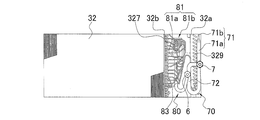
- the refrigerant temperature sensor 183 is attached to the second U-shaped portion 329 in the third stage as shown in FIG.
- the reason why the refrigerant temperature sensor 183 is attached to the second U-shaped portion 329 of the indoor heat exchanger 32 is that there is a plurality of fins between the first side end portion 32a and the second side end portion 32b, so that an effective installation space is secured. Therefore, it is inevitably attached to either the first U-shaped portion 327 or the second U-shaped portion 329.
- the first U-shaped portion 327 that is a portion close to the liquid with respect to the flow of the refrigerant flowing through the refrigerant path P. Therefore, it is preferable to attach to the second U-shaped portion 329 which is a portion near the gas side end.
- the attachment position of the refrigerant temperature sensor 183 may be attached to the uppermost refrigerant path P of the indoor heat exchanger 32.
- FIG. 8 is a graph showing the temperature distribution in the indoor heat exchanger 32 during the heating minimum capacity operation.
- the vertical axis indicates the detection value of the refrigerant temperature sensor 183
- the horizontal axis indicates the position of the refrigerant path
- the position number of the uppermost refrigerant path P of the indoor heat exchanger 32 is set to 1, and the downward direction The location number increases as you go.
- the values other than the uppermost refrigerant path P indicate values that are far from the saturation temperature as the position number of the refrigerant path increases. (Plot ⁇ ).
- the refrigerant path P from the uppermost stage to the eighth stage refrigerant path P shows a value close to the saturation temperature. Indicates a value far from the saturation temperature (plot ⁇ ).
- the refrigerant path P from the uppermost stage to the thirteenth stage of the refrigerant path P shows a value close to the saturation temperature.
- the values are far from each other (plot ⁇ ).
- the mounting position of the refrigerant temperature sensor 183 is higher than the center in the height direction of the indoor heat exchanger 32 in the use state, or higher than the flow divider main body 81a.
- the refrigerant temperature sensor 183 is attached to the refrigerant path P within a range that occupies 30% of the total number of the refrigerant paths P among the plurality of refrigerant paths P counting from the refrigerant path P located at the uppermost stage. In addition, an accurate saturation temperature can be detected more reliably.
- the refrigerant temperature sensor 183 avoids the first side end 32 a side of the indoor heat exchanger 32, which is a portion near the liquid, with respect to the flow of the refrigerant flowing through the refrigerant path P, and the gas side end. Since it is attached to the second side end portion 32b side of the indoor heat exchanger 32, which is closer, it is avoided that the saturation temperature cannot be detected when the entire system is subcooled.
- the “minimum heating operation state in which the compressor 12 continuously operates for 30 seconds or more at a low compressor rotation speed that provides a minimum heating capacity that is less than 45% of the rated heating capacity” may appear. If the range of the compressor 12 that can be used is prepared, the indoor heat exchanger 32 can be operated even if the refrigerant circulation amount is reduced because the compressor 12 is operated at such a low rotational speed that the minimum heating capacity is obtained. Since no liquid pool is generated above the center in the height direction or above the flow divider main body 81a, the refrigerant temperature sensor 183 attached to the region can detect an accurate saturation temperature.
- FIG. 9 is a schematic diagram showing the positional relationship of the flow divider 81 with respect to the height direction of the indoor heat exchanger 132 in the use state, which is the indoor heat exchanger 132 used in the floor-standing indoor unit.
- the indoor heat exchanger 132 in use is in an inclined posture, and ten refrigerant paths P are arranged from the upper stage toward the lower stage.
- the intervals between the refrigerant paths P are not uniform.
- the connecting portion between the flow divider main body 81a and the flow dividing pipe 81b is set slightly lower than the height position of the refrigerant path P in the sixth stage from the top of the indoor heat exchanger 132, and the height of the indoor heat exchanger 132 is increased. It corresponds to the central part in the vertical direction.
- the connecting portion between the flow divider main body 81a and the flow dividing pipe 81b is directed vertically upward, the flow dividing pipe 81b connected from the uppermost refrigerant path P of the indoor heat exchanger 132 to each of the sixth refrigerant paths P. Is at a position higher than the connecting portion between the flow divider main body 81a and the flow dividing pipe 81b.
- the branch pipe 81b connected to each of the seventh-stage refrigerant path P to the tenth-stage refrigerant path P of the indoor heat exchanger 132 is located at a position lower than the connection portion between the flow divider main body 81a and the branch pipe 81b. .
- the liquid refrigerant flowing through the branch pipes 81b connected from the uppermost refrigerant path P to the sixth refrigerant path P of the indoor heat exchanger 132 flows against gravity, and the indoor heat
- the liquid refrigerant flowing through the diverter pipe 81b connected from the seventh stage heat transfer pipe to the tenth stage heat transfer pipe of the exchanger 132 flows without resisting gravity.
- the liquid refrigerant flowing through the flow dividing pipe 81b connected from the uppermost refrigerant path P to the sixth refrigerant path P of the indoor heat exchanger 132 flows without resisting gravity.
- the liquid refrigerant flowing through the diverter pipe 81b connected from the seventh-stage refrigerant path P to the tenth-stage refrigerant path P of the heat exchanger 132 flows against gravity.
- the mounting position of the refrigerant temperature sensor 183 As in the case of the indoor heat exchanger in the above-described embodiment, in order to correctly detect the saturation temperature even when a liquid pool occurs in the operating state in the low circulation amount region. As shown in FIG. 9, it is attached to the refrigerant path P so as to be above the center in the height direction of the indoor heat exchanger 132 in the use state or above the flow divider main body 81a. Is desirable. Further, it is preferable to attach to the portion near the gas side end while avoiding the portion close to the liquid with respect to the flow of the refrigerant flowing through the refrigerant path P.
- FIG. 10 is a graph showing the temperature distribution in the indoor heat exchanger 132 during the heating minimum capacity operation.
- the vertical axis indicates the detection value of the refrigerant temperature sensor 183
- the horizontal axis indicates the position of the refrigerant path P
- the position number of the uppermost refrigerant path P of the indoor heat exchanger 132 is set to 1, and The position number increases as you go to.
- the refrigerant temperature sensor 183 when the refrigerant temperature sensor 183 is disposed closer to the gas in the refrigerant path P, the values from the uppermost stage to the eighth stage refrigerant path P show values close to the saturation temperature, and the lowermost ninth and tenth stages. Only the refrigerant path P shows a value far from the saturation temperature (plot ⁇ ).
- the mounting position of the refrigerant temperature sensor 183 is higher than the center in the height direction of the indoor heat exchanger 132 in the use state, or higher than the flow divider main body 81a.
- FIG. 11 is a schematic diagram showing the positional relationship of the flow divider 81 with respect to the height direction of the indoor heat exchanger 232 in the use state, which is the indoor heat exchanger 232 used in the two-way blowout indoor unit.
- the indoor heat exchanger 232 has a configuration in which two heat exchangers face each other, and seven refrigerant paths P are arranged from the upper stage toward the lower stage.
- the connecting portion between the flow divider main body 81a and the flow dividing pipe 81b is set slightly higher than the height position of the fourth-stage refrigerant path P from above the indoor heat exchanger 232, and the height of the indoor heat exchanger 232 is increased. Corresponds to approximately the center in the vertical direction.
- the connecting portion between the flow divider main body 81a and the flow dividing pipe 81b is directed vertically upward, the flow dividing pipe 81b connected from the uppermost refrigerant path P of the indoor heat exchanger 232 to each of the third heat transfer pipes is , At a position higher than the connecting portion between the flow divider main body 81a and the flow dividing pipe 81b.
- the branch pipe 81b connected to each of the fourth-stage refrigerant path P to the seventh-stage refrigerant path P of the indoor heat exchanger 232 is located at a position lower than the connection portion between the divider body 81a and the branch pipe 81b. .
- the liquid refrigerant flowing through the flow dividing pipe 81b connected from the uppermost refrigerant path P to the third refrigerant path P of the indoor heat exchanger 232 flows against the gravity, and the indoor heat
- the liquid refrigerant flowing through the branch pipes 81b connected from the fourth-stage refrigerant path P to the seventh-stage refrigerant path P of the exchanger 232 flows without resisting gravity.
- the liquid refrigerant flowing through the branch pipes 81b connected from the uppermost refrigerant path P to the third refrigerant path P of the indoor heat exchanger 232 flows without resisting gravity.
- the liquid refrigerant flowing through the branch pipes 81b connected from the fourth-stage refrigerant path P to the seventh-stage refrigerant path P of the heat exchanger 232 flows against gravity.
- the mounting position of the refrigerant temperature sensor 183 As in the case of the indoor heat exchanger in the above-described embodiment, in order to correctly detect the saturation temperature even when a liquid pool occurs in the operating state in the low circulation amount region. As shown in FIG. 11, it is attached to the refrigerant path P so as to be above the center in the height direction of the indoor heat exchanger 232 in the use state or above the flow divider main body 81a. Is desirable. Further, it is preferable to attach to the portion near the gas side end while avoiding the portion close to the liquid with respect to the flow of the refrigerant flowing through the refrigerant path P.
- the present invention is useful for an air-conditioning apparatus that can naturally bring about a minimum heating operation state.
Landscapes
- Engineering & Computer Science (AREA)
- Mechanical Engineering (AREA)
- General Engineering & Computer Science (AREA)
- Chemical & Material Sciences (AREA)
- Combustion & Propulsion (AREA)
- Physics & Mathematics (AREA)
- Thermal Sciences (AREA)
- Air Conditioning Control Device (AREA)
Abstract
La présente invention a pour objet un dispositif de climatisation qui effectue une opération de chauffage en amenant un échangeur de chaleur intérieur à servir de radiateur d'un caloporteur, la température de saturation de l'air pouvant être détectée correctement même lorsqu'une accumulation de liquide se produit dans un état de fonctionnement dans une zone à faible circulation. Dans le dispositif de climatisation (10) selon l'invention, même lorsqu'un compresseur (12) est amené à fonctionner à un faible nombre de rotations de compresseur de manière à produire la performance de chauffage minimal et lorsque la circulation de caloporteur diminue, l'accumulation de liquide ne se produit pas au-dessus du centre dans la direction de la hauteur d'un échangeur de chaleur intérieur (32) ou au-dessus d'un corps distributeur (81a). Par conséquent, un capteur (183) de température de caloporteur fixée à la zone susmentionnée permet de détecter la température de saturation précise. Cela élimine tout risque de panne de commande de sous-refroidissement, rend superflue la commande d'une action d'ouverture de soupape motorisée uniquement pour l'élimination de l'accumulation de liquide comme dans l'état de la technique et, comme cela sera évident, évite d'avoir à fournir un capteur de pression.
Priority Applications (4)
| Application Number | Priority Date | Filing Date | Title |
|---|---|---|---|
| CN201680007877.0A CN107208954B (zh) | 2015-01-29 | 2016-01-21 | 空调装置 |
| ES16743227T ES2753852T3 (es) | 2015-01-29 | 2016-01-21 | Dispositivo de acondicionamiento de aire |
| AU2016213420A AU2016213420B2 (en) | 2015-01-29 | 2016-01-21 | Air conditioning apparatus |
| EP16743227.7A EP3252401B1 (fr) | 2015-01-29 | 2016-01-21 | Dispositif de climatisation |
Applications Claiming Priority (2)
| Application Number | Priority Date | Filing Date | Title |
|---|---|---|---|
| JP2015016005A JP6307028B2 (ja) | 2015-01-29 | 2015-01-29 | 空気調和装置 |
| JP2015-016005 | 2015-01-29 |
Publications (1)
| Publication Number | Publication Date |
|---|---|
| WO2016121623A1 true WO2016121623A1 (fr) | 2016-08-04 |
Family
ID=56543237
Family Applications (1)
| Application Number | Title | Priority Date | Filing Date |
|---|---|---|---|
| PCT/JP2016/051743 Ceased WO2016121623A1 (fr) | 2015-01-29 | 2016-01-21 | Dispositif de climatisation |
Country Status (6)
| Country | Link |
|---|---|
| EP (1) | EP3252401B1 (fr) |
| JP (1) | JP6307028B2 (fr) |
| CN (1) | CN107208954B (fr) |
| AU (1) | AU2016213420B2 (fr) |
| ES (1) | ES2753852T3 (fr) |
| WO (1) | WO2016121623A1 (fr) |
Cited By (2)
| Publication number | Priority date | Publication date | Assignee | Title |
|---|---|---|---|---|
| CN119826304A (zh) * | 2025-03-03 | 2025-04-15 | 广东希塔变频技术有限公司 | 一种基于连接管的空调频率调节方法及系统 |
| US12287109B2 (en) | 2021-01-29 | 2025-04-29 | Daikin Industries, Ltd. | Air blower |
Families Citing this family (6)
| Publication number | Priority date | Publication date | Assignee | Title |
|---|---|---|---|---|
| EP3575730A4 (fr) * | 2017-01-24 | 2020-01-15 | Mitsubishi Electric Corporation | Unité côté source de chaleur et dispositif à cycle de réfrigération |
| WO2019106755A1 (fr) * | 2017-11-29 | 2019-06-06 | 三菱電機株式会社 | Climatiseur |
| CN109900062B (zh) * | 2019-04-04 | 2021-07-20 | 湖北美的电冰箱有限公司 | 环境温度确定方法、计算机可读存储介质和制冷设备 |
| CN110686375B (zh) * | 2019-09-10 | 2021-01-15 | 珠海格力电器股份有限公司 | 空调换热介质控制方法、装置、介质、计算机设备及空调 |
| US11754204B2 (en) | 2020-07-27 | 2023-09-12 | Hanon Systems | Stabilized h-plate |
| WO2024224511A1 (fr) * | 2023-04-26 | 2024-10-31 | 三菱電機株式会社 | Échangeur de chaleur |
Citations (3)
| Publication number | Priority date | Publication date | Assignee | Title |
|---|---|---|---|---|
| JPH07127942A (ja) * | 1993-11-08 | 1995-05-19 | Sanyo Electric Co Ltd | 冷凍装置 |
| JP2000088362A (ja) * | 1998-09-10 | 2000-03-31 | Matsushita Refrig Co Ltd | ヒートポンプ式空気調和機 |
| JP2013137165A (ja) * | 2011-12-28 | 2013-07-11 | Daikin Industries Ltd | 冷凍装置 |
Family Cites Families (8)
| Publication number | Priority date | Publication date | Assignee | Title |
|---|---|---|---|---|
| JP3843331B2 (ja) * | 1999-08-27 | 2006-11-08 | 株式会社日立製作所 | ヒートポンプ式空気調和機及び室外機 |
| US6868678B2 (en) * | 2002-03-26 | 2005-03-22 | Ut-Battelle, Llc | Non-intrusive refrigerant charge indicator |
| CN1969153A (zh) * | 2005-01-12 | 2007-05-23 | 松下电器产业株式会社 | 冷热水分配器及其控制方法 |
| JP2006292329A (ja) * | 2005-04-14 | 2006-10-26 | Mitsubishi Heavy Ind Ltd | 熱源システムおよびその制御装置ならびにその制御方法 |
| KR100700545B1 (ko) * | 2005-08-10 | 2007-03-28 | 엘지전자 주식회사 | 복수의 압축기를 구비한 공기조화기의 운전제어장치 및방법 |
| WO2009038624A1 (fr) * | 2007-09-19 | 2009-03-26 | Emerson Climate Technologies, Inc. | Système et procédé de contrôle de réfrigération |
| JP2013011364A (ja) * | 2011-06-28 | 2013-01-17 | Daikin Industries Ltd | 空気調和装置 |
| JP6053201B2 (ja) * | 2013-02-06 | 2016-12-27 | ダイキン工業株式会社 | 冷凍装置 |
-
2015
- 2015-01-29 JP JP2015016005A patent/JP6307028B2/ja active Active
-
2016
- 2016-01-21 CN CN201680007877.0A patent/CN107208954B/zh active Active
- 2016-01-21 EP EP16743227.7A patent/EP3252401B1/fr active Active
- 2016-01-21 AU AU2016213420A patent/AU2016213420B2/en active Active
- 2016-01-21 ES ES16743227T patent/ES2753852T3/es active Active
- 2016-01-21 WO PCT/JP2016/051743 patent/WO2016121623A1/fr not_active Ceased
Patent Citations (3)
| Publication number | Priority date | Publication date | Assignee | Title |
|---|---|---|---|---|
| JPH07127942A (ja) * | 1993-11-08 | 1995-05-19 | Sanyo Electric Co Ltd | 冷凍装置 |
| JP2000088362A (ja) * | 1998-09-10 | 2000-03-31 | Matsushita Refrig Co Ltd | ヒートポンプ式空気調和機 |
| JP2013137165A (ja) * | 2011-12-28 | 2013-07-11 | Daikin Industries Ltd | 冷凍装置 |
Cited By (2)
| Publication number | Priority date | Publication date | Assignee | Title |
|---|---|---|---|---|
| US12287109B2 (en) | 2021-01-29 | 2025-04-29 | Daikin Industries, Ltd. | Air blower |
| CN119826304A (zh) * | 2025-03-03 | 2025-04-15 | 广东希塔变频技术有限公司 | 一种基于连接管的空调频率调节方法及系统 |
Also Published As
| Publication number | Publication date |
|---|---|
| EP3252401A4 (fr) | 2018-02-28 |
| AU2016213420A1 (en) | 2017-09-21 |
| EP3252401A1 (fr) | 2017-12-06 |
| EP3252401B1 (fr) | 2019-08-07 |
| JP6307028B2 (ja) | 2018-04-04 |
| CN107208954A (zh) | 2017-09-26 |
| JP2016142414A (ja) | 2016-08-08 |
| ES2753852T3 (es) | 2020-04-14 |
| AU2016213420B2 (en) | 2018-11-01 |
| CN107208954B (zh) | 2020-10-09 |
Similar Documents
| Publication | Publication Date | Title |
|---|---|---|
| JP6307028B2 (ja) | 空気調和装置 | |
| US10161656B2 (en) | Air conditioner having a bending tube which alters the flow of the refrigerant prior to entering the distributor | |
| CN105008809B (zh) | 空调机的室内机组 | |
| US9568221B2 (en) | Indoor unit for air conditioning device | |
| JP5581671B2 (ja) | 空調室外機 | |
| EP2993423B1 (fr) | Panneau décoratif et unité d'intérieur de conditionneur d'air le comportant | |
| EP2985542A1 (fr) | Panneau décoratif et unité intérieure de climatiseur comprenant celui-ci | |
| JP6149494B2 (ja) | 化粧パネル、及び空気調和機の室内ユニット | |
| KR101550550B1 (ko) | 공기 조화기 | |
| CN107270402A (zh) | 空调室内机 | |
| EP3392573B1 (fr) | Machine d'extérieur pour appareil à cycle de congélation | |
| CN107166540A (zh) | 空调室内机 | |
| CN109196288B (zh) | 多联型空调装置 | |
| CN206919178U (zh) | 空调室内机 | |
| CN207006372U (zh) | 空调室内机 | |
| CN207146530U (zh) | 空调室内机 | |
| JP2025156603A (ja) | 空調機 | |
| CN107420986A (zh) | 空调室内机 |
Legal Events
| Date | Code | Title | Description |
|---|---|---|---|
| 121 | Ep: the epo has been informed by wipo that ep was designated in this application |
Ref document number: 16743227 Country of ref document: EP Kind code of ref document: A1 |
|
| NENP | Non-entry into the national phase |
Ref country code: DE |
|
| REEP | Request for entry into the european phase |
Ref document number: 2016743227 Country of ref document: EP |
|
| ENP | Entry into the national phase |
Ref document number: 2016213420 Country of ref document: AU Date of ref document: 20160121 Kind code of ref document: A |