WO2016121956A1 - Stratifié-verre et dispositif électronique portable - Google Patents
Stratifié-verre et dispositif électronique portable Download PDFInfo
- Publication number
- WO2016121956A1 WO2016121956A1 PCT/JP2016/052736 JP2016052736W WO2016121956A1 WO 2016121956 A1 WO2016121956 A1 WO 2016121956A1 JP 2016052736 W JP2016052736 W JP 2016052736W WO 2016121956 A1 WO2016121956 A1 WO 2016121956A1
- Authority
- WO
- WIPO (PCT)
- Prior art keywords
- glass
- glass laminate
- laminate according
- wavelength
- less
- Prior art date
- Legal status (The legal status is an assumption and is not a legal conclusion. Google has not performed a legal analysis and makes no representation as to the accuracy of the status listed.)
- Ceased
Links
Images





Classifications
-
- B—PERFORMING OPERATIONS; TRANSPORTING
- B32—LAYERED PRODUCTS
- B32B—LAYERED PRODUCTS, i.e. PRODUCTS BUILT-UP OF STRATA OF FLAT OR NON-FLAT, e.g. CELLULAR OR HONEYCOMB, FORM
- B32B17/00—Layered products essentially comprising sheet glass, or glass, slag, or like fibres
- B32B17/06—Layered products essentially comprising sheet glass, or glass, slag, or like fibres comprising glass as the main or only constituent of a layer, next to another layer of a specific material
-
- C—CHEMISTRY; METALLURGY
- C03—GLASS; MINERAL OR SLAG WOOL
- C03C—CHEMICAL COMPOSITION OF GLASSES, GLAZES OR VITREOUS ENAMELS; SURFACE TREATMENT OF GLASS; SURFACE TREATMENT OF FIBRES OR FILAMENTS MADE FROM GLASS, MINERALS OR SLAGS; JOINING GLASS TO GLASS OR OTHER MATERIALS
- C03C17/00—Surface treatment of glass, not in the form of fibres or filaments, by coating
- C03C17/34—Surface treatment of glass, not in the form of fibres or filaments, by coating with at least two coatings having different compositions
-
- C—CHEMISTRY; METALLURGY
- C03—GLASS; MINERAL OR SLAG WOOL
- C03C—CHEMICAL COMPOSITION OF GLASSES, GLAZES OR VITREOUS ENAMELS; SURFACE TREATMENT OF GLASS; SURFACE TREATMENT OF FIBRES OR FILAMENTS MADE FROM GLASS, MINERALS OR SLAGS; JOINING GLASS TO GLASS OR OTHER MATERIALS
- C03C17/00—Surface treatment of glass, not in the form of fibres or filaments, by coating
- C03C17/34—Surface treatment of glass, not in the form of fibres or filaments, by coating with at least two coatings having different compositions
- C03C17/3411—Surface treatment of glass, not in the form of fibres or filaments, by coating with at least two coatings having different compositions with at least two coatings of inorganic materials
- C03C17/3417—Surface treatment of glass, not in the form of fibres or filaments, by coating with at least two coatings having different compositions with at least two coatings of inorganic materials all coatings being oxide coatings
-
- C—CHEMISTRY; METALLURGY
- C03—GLASS; MINERAL OR SLAG WOOL
- C03C—CHEMICAL COMPOSITION OF GLASSES, GLAZES OR VITREOUS ENAMELS; SURFACE TREATMENT OF GLASS; SURFACE TREATMENT OF FIBRES OR FILAMENTS MADE FROM GLASS, MINERALS OR SLAGS; JOINING GLASS TO GLASS OR OTHER MATERIALS
- C03C17/00—Surface treatment of glass, not in the form of fibres or filaments, by coating
- C03C17/34—Surface treatment of glass, not in the form of fibres or filaments, by coating with at least two coatings having different compositions
- C03C17/42—Surface treatment of glass, not in the form of fibres or filaments, by coating with at least two coatings having different compositions at least one coating of an organic material and at least one non-metal coating
-
- B—PERFORMING OPERATIONS; TRANSPORTING
- B32—LAYERED PRODUCTS
- B32B—LAYERED PRODUCTS, i.e. PRODUCTS BUILT-UP OF STRATA OF FLAT OR NON-FLAT, e.g. CELLULAR OR HONEYCOMB, FORM
- B32B2307/00—Properties of the layers or laminate
- B32B2307/40—Properties of the layers or laminate having particular optical properties
- B32B2307/418—Refractive
-
- B—PERFORMING OPERATIONS; TRANSPORTING
- B32—LAYERED PRODUCTS
- B32B—LAYERED PRODUCTS, i.e. PRODUCTS BUILT-UP OF STRATA OF FLAT OR NON-FLAT, e.g. CELLULAR OR HONEYCOMB, FORM
- B32B2307/00—Properties of the layers or laminate
- B32B2307/50—Properties of the layers or laminate having particular mechanical properties
- B32B2307/538—Roughness
-
- B—PERFORMING OPERATIONS; TRANSPORTING
- B32—LAYERED PRODUCTS
- B32B—LAYERED PRODUCTS, i.e. PRODUCTS BUILT-UP OF STRATA OF FLAT OR NON-FLAT, e.g. CELLULAR OR HONEYCOMB, FORM
- B32B2457/00—Electrical equipment
-
- C—CHEMISTRY; METALLURGY
- C03—GLASS; MINERAL OR SLAG WOOL
- C03C—CHEMICAL COMPOSITION OF GLASSES, GLAZES OR VITREOUS ENAMELS; SURFACE TREATMENT OF GLASS; SURFACE TREATMENT OF FIBRES OR FILAMENTS MADE FROM GLASS, MINERALS OR SLAGS; JOINING GLASS TO GLASS OR OTHER MATERIALS
- C03C2217/00—Coatings on glass
- C03C2217/20—Materials for coating a single layer on glass
- C03C2217/21—Oxides
- C03C2217/213—SiO2
-
- C—CHEMISTRY; METALLURGY
- C03—GLASS; MINERAL OR SLAG WOOL
- C03C—CHEMICAL COMPOSITION OF GLASSES, GLAZES OR VITREOUS ENAMELS; SURFACE TREATMENT OF GLASS; SURFACE TREATMENT OF FIBRES OR FILAMENTS MADE FROM GLASS, MINERALS OR SLAGS; JOINING GLASS TO GLASS OR OTHER MATERIALS
- C03C2217/00—Coatings on glass
- C03C2217/20—Materials for coating a single layer on glass
- C03C2217/21—Oxides
- C03C2217/218—V2O5, Nb2O5, Ta2O5
-
- C—CHEMISTRY; METALLURGY
- C03—GLASS; MINERAL OR SLAG WOOL
- C03C—CHEMICAL COMPOSITION OF GLASSES, GLAZES OR VITREOUS ENAMELS; SURFACE TREATMENT OF GLASS; SURFACE TREATMENT OF FIBRES OR FILAMENTS MADE FROM GLASS, MINERALS OR SLAGS; JOINING GLASS TO GLASS OR OTHER MATERIALS
- C03C2217/00—Coatings on glass
- C03C2217/70—Properties of coatings
- C03C2217/73—Anti-reflective coatings with specific characteristics
- C03C2217/734—Anti-reflective coatings with specific characteristics comprising an alternation of high and low refractive indexes
-
- C—CHEMISTRY; METALLURGY
- C03—GLASS; MINERAL OR SLAG WOOL
- C03C—CHEMICAL COMPOSITION OF GLASSES, GLAZES OR VITREOUS ENAMELS; SURFACE TREATMENT OF GLASS; SURFACE TREATMENT OF FIBRES OR FILAMENTS MADE FROM GLASS, MINERALS OR SLAGS; JOINING GLASS TO GLASS OR OTHER MATERIALS
- C03C2218/00—Methods for coating glass
- C03C2218/10—Deposition methods
- C03C2218/15—Deposition methods from the vapour phase
- C03C2218/154—Deposition methods from the vapour phase by sputtering
-
- H—ELECTRICITY
- H05—ELECTRIC TECHNIQUES NOT OTHERWISE PROVIDED FOR
- H05K—PRINTED CIRCUITS; CASINGS OR CONSTRUCTIONAL DETAILS OF ELECTRIC APPARATUS; MANUFACTURE OF ASSEMBLAGES OF ELECTRICAL COMPONENTS
- H05K5/00—Casings, cabinets or drawers for electric apparatus
- H05K5/0086—Casings, cabinets or drawers for electric apparatus portable, e.g. battery operated apparatus
Definitions
- the present invention relates to a glass laminate and a portable electronic device, and particularly to a glass laminate excellent in design and a portable electronic device using the same.
- appropriate materials are selected from materials such as resin and metal in consideration of various factors such as decoration, scratch resistance, workability, and cost. .
- the present invention has been made to solve the above-described problems, and is suitable for exterior use such as a casing of an electronic device, and aims to provide a glass laminate having excellent design properties. .
- the glass laminate of the present invention has a glass substrate and an antireflection layer laminated on the glass substrate.
- the minimum absorbance at a wavelength of 380 to 780 nm is 0.01 or more.
- a glass laminate that is suitably used for a housing or the like of an electronic device and has excellent design properties.
- a glass laminate having a deep color can be provided.
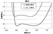
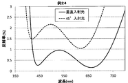
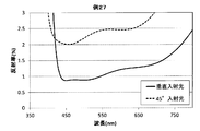
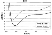
- Sectional drawing which shows one Embodiment of a glass laminated body. Sectional drawing which shows the antireflection layer of the glass laminated body shown in FIG. The figure which shows the measurement result of the spectral reflectance of Example 21. The figure which shows the measurement result of the spectral reflectance of Example 22. The figure which shows the measurement result of the spectral reflectance of Example 23. The figure which shows the measurement result of the spectral reflectance of Example 24. The figure which shows the measurement result of the spectral reflectance of Example 25. The figure which shows the measurement result of the spectral reflectance of Example 26. The figure which shows the measurement result of the spectral reflectance of Example 27. The figure which shows the measurement result of the spectral reflectance of Example 28.
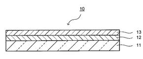
- FIG. 1 is a cross-sectional view showing an embodiment of a glass laminate.
- FIG. 2 is sectional drawing which shows the antireflection layer of the glass laminated body shown in FIG.
- the glass laminate 10 has, for example, a glass substrate 11, an antireflection layer 12, and an antifouling layer 13.
- the antireflection layer 12 and the antifouling layer 13 are provided in this order on one main surface side of the glass substrate 11.
- the glass laminate 10 has a minimum absorbance of 0.01 or more at a wavelength of 380 to 780 nm.
- the minimum value is 0.01 or more
- the appearance of the glass laminate 10 is colored.
- the antireflection layer 12 is provided, so that the depth of the black or the rich color is given and the design is improved.
- the color of the glass laminate 10 is black or a dense color
- things such as gloss and whiteness on the surface are suppressed, and a deep color can be obtained.
- the glass substrate 11 is made of a glass material, and makes the minimum absorbance of the glass laminate 10 at a wavelength of 380 to 780 nm 0.01 or more. From the viewpoint of setting the minimum absorbance of the glass laminate 10 at a wavelength of 380 to 780 nm to 0.01 or more, the minimum absorbance of the glass substrate 11 at a wavelength of 380 to 780 nm is preferably 0.01 or more. As such a glass substrate 11, colored glass is preferable.
- coloring component examples include metal oxides such as Co, Mn, Fe, Ni, Cu, Cr, V, Bi, Se, Ti, Ce, Er, and Nd.
- metal oxides such as Co, Mn, Fe, Ni, Cu, Cr, V, Bi, Se, Ti, Ce, Er, and Nd.
- the content of the coloring component is preferably 0.001 to 7% in terms of oxide-based molar percentage in the colored glass.
- content of a coloring component is less than 0.001%, the effect as a coloring component cannot fully be acquired.
- the minimum absorbance of the glass substrate 11 at a wavelength of 380 to 780 nm does not become 0.01 or more, and as a result, the minimum absorbance of the glass laminate 10 at a wavelength of 380 to 780 nm may not become 0.01 or more. There is.
- the content of the coloring component is preferably 0.1% or more, more preferably 0.2% or more, still more preferably 1% or more, and particularly preferably 2% or more. Moreover, when content of a coloring component exceeds 7%, there exists a possibility that glass may become unstable and may cause devitrification.
- the content of the coloring component is preferably 5% or less, more preferably 4% or less, from the viewpoint of the stability of the glass.
- the colored glass together with the coloring components, is expressed in terms of a molar percentage on the basis of oxide, with SiO 2 being 55 to 80%, Al 2 O 3 being 0 to 16%, B 2 O 3 being 0 to 12%, and Na 2 O being 5 ⁇ 20%, K 2 O 0 ⁇ 8%, MgO 0 ⁇ 15%, CaO 0 ⁇ 15%, ⁇ RO (R is Mg, Ca, Sr, Ba, Zn) 0 ⁇ 18%, ZrO 2 Is preferably contained in an amount of 0-5%.
- the composition of the glass other than the coloring components in the colored glass will be described using the mole percentage display content unless otherwise specified.
- SiO 2 is a component constituting the skeleton of the glass and is essential. If it is less than 55%, the stability and weather resistance of the glass may be lowered. Preferably it is 60% or more, more preferably 65% or more. If it exceeds 80%, the viscosity of the glass may increase and the meltability may decrease. Preferably it is 75% or less, More preferably, it is 70% or less.
- Al 2 O 3 is a component that improves the weather resistance and chemical strengthening properties of the glass, and is not essential, but can be contained as necessary. When it is 1% or more, weather resistance is improved, which is preferable. More preferably, it is 2% or more, and further preferably 3% or more. If it exceeds 16%, the viscosity of the glass tends to be high, and homogeneous melting may be difficult. Preferably it is 14% or less, More preferably, it is 12% or less.
- B 2 O 3 is a component for improving the weather resistance of glass, but not necessarily be contained as necessary. If it is 4% or more, the weather resistance is remarkably improved, which is preferable. More preferably, it is 5% or more, and further preferably 6% or more. If it exceeds 12%, striae due to volatilization may occur and the yield may decrease. Preferably it is 11% or less, More preferably, it is 10% or less.
- Na 2 O is a component that improves the meltability of the glass, and is contained in order to form a surface compressive stress layer by ion exchange. If it is less than 5%, the meltability is poor, and it may be difficult to form a desired surface compressive stress layer by ion exchange. Preferably it is 7% or more, More preferably, it is 8% or more. If it exceeds 20%, the weather resistance may decrease. Preferably it is 18% or less, More preferably, it is 17% or less.
- K 2 O is not essential, but is preferably a component that improves the meltability of the glass and has an effect of increasing the ion exchange rate in chemical strengthening. If it is 0.01% or more, the meltability, the ion exchange rate and the like are remarkably improved, which is preferable. More preferably, it is 0.1% or more. If it exceeds 8%, the weather resistance may decrease. Preferably it is 6% or less, More preferably, it is 5% or less.
- MgO is a component that improves the meltability of the glass, and is not essential, but can be contained if necessary. If it is 3% or more, the meltability is remarkably improved, which is preferable. More preferably, it is 4% or more. If it exceeds 15%, the weather resistance may deteriorate. Preferably it is 13% or less, More preferably, it is 12% or less.
- CaO is a component that improves the meltability of the glass and can be contained as necessary. If it is 0.01% or more, the meltability is remarkably improved, which is preferable. More preferably, it is 0.1% or more. If it exceeds 15%, the chemical strengthening properties may deteriorate. Preferably it is 13% or less, More preferably, it is 12% or less.
- SrO, BaO, and ZnO are also components that improve the meltability of the glass.
- ⁇ RO total content of these ROs
- the meltability is improved, which is preferable. More preferably, it is 3% or more, and further preferably 5% or more. If it exceeds 18%, the weather resistance is lowered. Preferably it is 15% or less, More preferably, it is 13% or less, More preferably, it is 11% or less.
- ZrO 2 is a component that increases the ion exchange rate, and is not essential, but can be contained in a range of 5% or less. If it exceeds 5%, the meltability may be deteriorated and remain in the glass as an unmelted product.
- Various molding methods can be adopted for molding colored glass. Specific examples include a downdraw method, a float method, a rollout method, and a press method. Examples of the downdraw method include an overflow downdraw method, a slot down method, and a redraw method.
- the colored glass may be chemically strengthened by ion exchange treatment to have high strength. Chemical strengthening increases the strength by forming a compressive stress layer on the surface layer of glass. Specifically, an alkali metal ion having a small ionic radius is exchanged with an alkali metal ion having a larger ionic radius at the glass transition temperature or lower.
- alkali metal ions having a small ion radius examples include Li ions and Na ions.
- examples of the alkali metal ion having a small ion radius include Li ion and Na ions.
- examples of the alkali metal ion having a larger ion radius include Na ion and K ion.
- examples of the alkali metal ion having a larger ion radius include K ion.
- the chemical strengthening is performed, for example, by immersing glass in a heated sodium nitrate (NaNO 3 ) molten salt or potassium nitrate (KNO 3 ) molten salt.
- NaNO 3 sodium nitrate
- KNO 3 potassium nitrate
- the conditions for chemical strengthening can be appropriately selected depending on the thickness of the glass, but the following conditions are usually preferred.
- the treatment temperature for chemical strengthening is preferably 350 to 550 ° C., more preferably 400 to 500 ° C.
- the chemical strengthening treatment time is preferably 0.5 to 144 hours, and more preferably 1 to 24 hours.
- the surface compressive stress layer In order to make the effect of improving the strength by chemical strengthening effective, it is preferable to make the surface compressive stress layer deeper than the microcracks generated on the surface of the glass. Here, microcracks are likely to occur when the surface of glass is roughened. For these reasons, the thickness of the surface compressive stress layer is preferably 6 ⁇ m or more.
- glass is easy to break when scratches generated during its use exceed the thickness of the surface compressive stress layer. For this reason, it is preferable to thicken the surface compressive stress layer. Specifically, 10 ⁇ m or more is more preferable, 15 ⁇ m or more is further preferable, 20 ⁇ m or more is further preferable, and 30 ⁇ m or more is particularly preferable.
- the depth of the surface compressive stress layer is preferably 70 ⁇ m or less, more preferably 60 ⁇ m or less, further preferably 50 ⁇ m or less, and particularly preferably 40 ⁇ m or less.
- the depth of the surface compressive stress layer is obtained as follows.
- the alkali ion concentration analysis of the depth direction of glass is performed by EPMA (electron probe microanalyzer, electron beam microanalyzer).
- EPMA electron probe microanalyzer, electron beam microanalyzer
- potassium ion concentration analysis is performed.
- the potassium ion diffusion depth obtained by the measurement is regarded as the depth of the surface compressive stress layer.
- the glass substrate 11 preferably has a surface roughness Ra measured in accordance with JIS B0633 (2001) of 0.2 to 1 ⁇ m.
- a surface roughness Ra of 0.2 ⁇ m or more is preferable because strength is improved. Further, when the surface roughness Ra is 1 ⁇ m or less, a change in appearance and texture is suppressed, and a desired color can be easily obtained.
- the surface roughness Ra can be adjusted by a physical method such as sand blasting or loose abrasive polishing using an abrasive, or a chemical method immersed in an etching solution.
- the surface roughness Ra can be measured with a laser microscope (for example, model number: VK8550, manufactured by Keyence Corporation).
- the thickness of the glass substrate 11 can be appropriately selected according to the use. From the viewpoint of securing strength, it is preferably 0.1 mm or more, more preferably 0.2 mm or more, and further preferably 0.5 mm or more. Moreover, 10 mm or less is preferable, 2.0 mm or less is more preferable, and 1.2 mm or less is further more preferable.
- the glass substrate 11 preferably has the following optical characteristics.
- the minimum absorbance at a wavelength of 380 to 780 nm is preferably 0.01 or more, more preferably 0.2 or more, further preferably 0.7 or more, and particularly preferably 1.0 or more.
- the minimum value is 0.01 or more, since the depth of the color of the glass laminated body 10 increases, it is preferable. Since the depth of the color of the glass laminated body 10 increases so that the said minimum value becomes large, it is preferable.
- the average value of absorbance at wavelengths of 380 to 780 nm is preferably 0.1 or more, more preferably 0.5 or more, still more preferably 2.0 or more, and particularly preferably 3.0 or more.
- the average value is preferable because the color depth of the glass laminate 10 increases as the average value increases.
- the lightness L * of the reflected light from the F2 light source of the L * a * b * color system is preferably less than 40. When the lightness L * is less than 40, it becomes close to black. For this reason, when the antireflection layer 12 is provided, the effect of increasing the color depth is increased.
- the lightness L * is more preferably 35 or less, and further preferably 30 or less.
- the lightness L * is preferably 1 or more, and more preferably 1.5 or more.
- the antireflection layer 12 is provided to add depth to the color of the glass laminate 10.
- the antireflection layer 12 is formed by laminating a high refractive index layer 121 and a low refractive index layer 122.
- the high refractive index layer 121 is a layer having a refractive index of 1.9 or more at a wavelength of 550 nm.
- the low refractive index layer 122 is a layer having a refractive index of 1.6 or less at a wavelength of 550 nm.
- the antireflection layer 12 is preferably provided on the main surface side which is the outside when the glass substrate 11 is used as a casing or the like of an electronic device.
- the antireflection layer 12 may include one high-refractive index layer 121 and one low-refractive index layer 122, or may include two or more layers. When two or more high refractive index layers 121 and low refractive index layers 122 are included, a form in which the high refractive index layers 121 and the low refractive index layers 122 are alternately stacked is preferable.
- the total number of layers of the high refractive index layer 121 and the low refractive index layer 122 is preferably 3 to 10, more preferably 2 to 6, and further preferably 2 to 4.
- the materials of the high refractive index layer 121 and the low refractive index layer 122 can be appropriately selected in consideration of antireflection performance, productivity, and the like.
- the high refractive index layer 121 As a constituent material of the high refractive index layer 121, niobium oxide (Nb 2 O 5 ), titanium oxide (TiO 2 ), zirconium oxide (ZrO 2 ), silicon nitride (SiN X ), tantalum oxide (Ta 2 O 5 ), etc. Is mentioned. Only 1 type may be used for these and 2 or more types may be used.
- the refractive index of the high refractive index layer 121 is preferably 1.9 to 2.7.
- Examples of the constituent material of the low refractive index layer 122 include silicon oxide (SiO 2 ), a composite oxide of Si and Sn, a composite oxide of Si and Zr, and a composite oxide of Si and Al. Only 1 type may be used for these and 2 or more types may be used.
- the refractive index of the low refractive index layer 122 is preferably 1.3 to 1.6.
- the high refractive index layer 121 is made of niobium oxide or tantalum oxide and the low refractive index layer 122 is made of silicon oxide.
- the high refractive index layer 121 is made of silicon nitride
- the low refractive index layer 122 is a composite oxide of Si and Sn, a composite oxide of Si and Zr, or It is preferably made of a complex oxide of Si and Al.
- the geometrical film thickness of the high refractive index layer 121 is preferably 5 nm or more, and more preferably 10 nm or more. Moreover, 200 nm or less is preferable respectively, and 150 nm or less is more preferable. Further, the geometric film thickness of the low refractive index layer 122 is preferably 5 nm or more, and more preferably 10 nm or more. Moreover, 150 nm or less is preferable respectively, and 100 nm or less is more preferable.
- the antireflection layer 12 preferably has a surface protective layer 123 as the uppermost layer in order to improve scratch resistance and the like.
- the surface protective layer 123 is made of, for example, an oxide containing at least one of zirconium and titanium and at least one of boron and silicon.
- Preferred examples include ZrBxOy, ZrSizOy, ZrBxSizOy, and TiSizOy.
- complex oxides containing zirconium and silicon ZrSizOy, ZrBxSizOy
- ZrBxSizOy complex oxides containing zirconium and silicon
- the hardness and refractive index of the surface protective layer 123 can be changed depending on the content ratio of boron, silicon, and oxygen and the film forming conditions. Therefore, it is preferable to select the content ratio of boron, silicon, and oxygen and the film forming conditions so that the desired hardness and refractive index are obtained.
- the film formation method of the antireflection layer 12 is not particularly limited, and various film formation methods can be used. Examples of the film forming method include pulse sputtering, AC sputtering, and digital sputtering. Pulse sputtering and AC sputtering are preferable because a dense film can be obtained.
- the antifouling layer 13 imparts antifouling properties and further adds color depth, and is provided as necessary.
- the antifouling layer 13 is made of, for example, a fluorine-containing organosilicon compound.
- a fluorine-containing organosilicon compound those imparting antifouling property, water repellency, or oil repellency can be used.
- fluorine-containing organosilicon compound for example, a fluorine-containing organosilicon compound having one or more groups selected from a polyfluoropolyether group, a polyfluoroalkylene group, and a polyfluoroalkyl group is preferable.
- the polyfluoropolyether group means a divalent group having a structure in which polyfluoroalkylene groups and etheric oxygen atoms are alternately bonded.
- fluorine-containing organosilicon compound having one or more groups selected from a polyfluoropolyether group, a polyfluoroalkylene group, and a polyfluoroalkyl group are represented by the following general formulas (I) to (V). Compounds.
- Rf is a linear polyfluoroalkyl group having 1 to 16 carbon atoms
- X is a hydrogen atom or a lower alkyl group having 1 to 5 carbon atoms
- R1 is a hydrolyzable group or halogen atom
- m is 1 to An integer of 50
- n is an integer of 0 to 2
- p is an integer of 1 to 10.
- Examples of the alkyl group in Rf include a methyl group, an ethyl group, an n-propyl group, an isopropyl group, and an n-butyl group.
- Examples of the lower alkyl group for X include a methyl group, an ethyl group, an n-propyl group, an isopropyl group, and an n-butyl group.
- Examples of the hydrolyzable group for R1 include an amino group and an alkoxy group.
- Examples of the halogen atom for R1 include fluorine, chlorine, bromine and iodine.
- m is preferably an integer of 1 to 30.
- n is preferably an integer of 1 to 2.
- p is preferably an integer of 1 to 8.
- q is 1 or more, preferably an integer of 2 to 20.
- Examples of the compound represented by the general formula (II) include n-trifluoro (1,1,2,2-tetrahydro) propylsilazane (n-CF 3 CH 2 CH 2 Si (NH 2 ) 3 ), n-heptafluoro ( 1,1,2,2-tetrahydro) pentylsilazane (nC 3 F 7 CH 2 CH 2 Si (NH 2 ) 3 ) and the like.
- q ′ is an integer of 1 or more, preferably 1-20.
- Examples of the compound represented by the general formula (III) include 2- (perfluorooctyl) ethyltrimethoxysilane (nC 8 F 17 CH 2 CH 2 Si (OCH 3 ) 3 ) and the like.
- R f2 is 2 represented by — (OC 3 F 6 ) s — (OC 2 F 4 ) t — (OCF 2 ) u — (s, t and u are each independently an integer of 0 to 300).
- Is a monovalent linear polyfluoropolyether group and R 2 and R 3 are each independently a monovalent hydrocarbon group having 1 to 8 carbon atoms.
- X 2 and X 3 are hydrolyzable groups or halogen atoms, and may be the same or different, d and e are independently integers of 1 to 2, and c and f are 1 to 5 (preferably 1 ⁇ 2) are mutually independent integers, and a and b are 2 ⁇ 3 mutually independent integers.
- Examples of the monovalent hydrocarbon group for R 2 and R 3 include a methyl group, an ethyl group, an n-propyl group, an isopropyl group, and an n-butyl group.
- Examples of the hydrolyzable group for X 2 and X 3 include an amino group, an alkoxy group, an acyloxy group, an alkenyloxy group, and an isocyanate group.
- Examples of the halogen atom for X 2 and X 3 include a fluorine atom, a chlorine atom, a bromine atom, and an iodine atom.
- s + t + u is preferably 20 to 200, more preferably 25 to 100.
- R 2 and R 3 are more preferably a methyl group, an ethyl group, or a butyl group.
- the hydrolyzable group represented by X 2 or X 3 is more preferably an alkoxy group having 1 to 6 carbon atoms, particularly preferably a methoxy group or an ethoxy group. Further, a and b are each preferably 3.
- v is an integer of 1 to 3
- w, y and z are each independently an integer of 0 to 200
- h is 1 or 2
- i is an integer of 2 to 20
- X 4 Is a hydrolyzable group
- R 4 is a linear or branched hydrocarbon group having 1 to 22 carbon atoms
- k is an integer of 0 to 2.
- w + y + z is preferably 20 to 300, more preferably 25 to 100. Further, i is preferably 2 to 10.
- X 4 is preferably an alkoxy group having 1 to 6 carbon atoms, more preferably a methoxy group or an ethoxy group. R 4 is preferably an alkyl group having 1 to 10 carbon atoms.
- fluorine-containing organosilicon compound having one or more groups selected from a polyfluoropolyether group, a polyfluoroalkylene group, and a polyfluoroalkyl group commercially available products can be used.
- examples of such products include KP-801 (trade name, manufactured by Shin-Etsu Chemical Co., Ltd.), KY178 (trade name, manufactured by Shin-Etsu Chemical Co., Ltd.), KY-130 (trade name, manufactured by Shin-Etsu Chemical Co., Ltd.), KY185 (trade name).
- Otsuru (registered trademark) DSX and OPTOOL (registered trademark) AES both trade names, manufactured by Daikin are preferable.
- the method for forming the antifouling layer 13 is not particularly limited, but it is preferable to form the film by vacuum deposition using the above materials.
- the geometrical film thickness of the antifouling layer 13 is preferably 1 nm or more from the viewpoint of effectively imparting antifouling properties. Further, the geometric film thickness of the antifouling layer 13 is preferably 15 nm or less, and more preferably 10 nm or less, from the viewpoint of productivity and the like.
- the glass laminate 10 of the present invention preferably has the following optical characteristics.
- the optical properties of the glass laminate 10 are measured in a state where at least the antireflection layer 12 is provided on the glass substrate 11. For example, when the glass laminated body 10 has the antireflection layer 12 and the antifouling layer 13, it measures in the state in which the antireflection layer 12 and the antifouling layer 13 were provided.
- the minimum absorbance at a wavelength of 380 to 780 nm is preferably 0.01 or more, more preferably 0.2 or more, further preferably 0.7 or more, and particularly preferably 1.0 or more.
- the minimum value is 0.01 or more, since the depth of the color of the glass laminated body 10 increases, it is preferable. Since the depth of the color of the glass laminated body 10 increases so that the said minimum value becomes large, it is preferable.
- the average value of absorbance at wavelengths of 380 to 780 nm is preferably 0.1 or more, more preferably 0.5 or more, still more preferably 2.0 or more, and particularly preferably 3.0 or more.
- the average value is preferable because the color depth of the glass laminate 10 increases as the average value increases.
- the minimum value of the spectral reflectance of normal incident light at a wavelength of 380 to 780 nm on the side where the antireflection layer 12 is provided with respect to the glass substrate 11 is preferably 3% or less.
- the minimum value is preferable because the color depth increases as the value becomes lower.
- the minimum value is preferably 2% or less, and more preferably 1% or less.
- the average value of the spectral reflectance of normal incident light at a wavelength of 380 to 780 nm on the side where the antireflection layer 12 is provided with respect to the glass substrate 11 is preferably 3% or less.
- the average value of 3% or less is particularly preferable because the reflection of illumination light or the like on the surface is suppressed and the color depth is increased.
- a lower average value is preferable because the color depth increases.
- the average value is preferably 2% or less, and more preferably 1.5% or less. Usually 0.2% is sufficient.
- the average value of the spectral reflectance of vertically incident light at a wavelength of 440 to 620 nm is preferably 0.3 to 2%. When the average value is 0.3 to 2%, it is possible to suppress illumination light or the like from being reflected on the glass laminate 10.
- the lightness L * of the reflected light by the F2 light source of the L * a * b * color system on the side where the antireflection layer 12 is provided with respect to the glass substrate 11 is preferably less than 25.
- a lightness L * of less than 25 is preferable because a sufficiently deep color can be obtained.
- the lightness L * is more preferably 20 or less, further preferably 15 or less, particularly preferably 10 or less, and most preferably 5 or less. Further, the lightness L * is preferably 1 or more, and more preferably 1.5 or more.
- the color of the reflected light of the glass laminate 10 may be either achromatic or chromatic. It is preferable that the glass laminated body 10 has the following optical characteristics according to the color of reflected light.
- the glass laminate 10 When making the reflected light color achromatic, the glass laminate 10 preferably has the following optical characteristics.
- the difference between the maximum value and the average value of the spectral reflectance of normal incidence light at a wavelength of 420 to 680 nm is preferably 0.5% or less, more preferably 0.4% or less, and further preferably 0.3% or less.
- the difference is 0.5% or less
- the reflected light is preferably an achromatic color having no specific color tone.
- the difference between the maximum value and the average value of the spectral reflectance of normal incidence light at a wavelength of 440 to 620 nm is preferably 0.3% or less, more preferably 0.25% or less, and further preferably 0.2% or less.
- the difference is 0.3% or less, when reflected light such as illumination light is recognized by the glass laminate 10, the reflected light is preferably an achromatic color having no specific color tone.
- the difference between the maximum value and the average value of the spectral reflectance of 45 ° incident light at a wavelength of 420 to 680 nm is preferably 1.0% or less, more preferably 0.9% or less, and even more preferably 0.8% or less.
- the difference is 1.0% or less, when reflected light such as illumination light is recognized by the glass laminate 10, the reflected light is preferably an achromatic color having no specific color tone.
- the difference between the maximum value and the average value of the spectral reflectance of 45 ° incident light at wavelengths of 440 to 620 nm is preferably 0.6% or less, more preferably 0.55% or less, and even more preferably 0.5% or less.
- the difference is 0.6% or less
- the reflected light is preferably an achromatic color having no specific color tone.
- the glass laminate 10 When making the color of reflected light chromatic, the glass laminate 10 preferably has the following optical characteristics.
- the difference between the maximum value and the average value of the spectral reflectance of normal incidence light at a wavelength of 420 to 680 nm is preferably more than 0.5%, more preferably more than 0.6%, still more preferably more than 0.7%.
- the difference exceeds 0.5%, when reflected light such as illumination light is recognized by the glass laminate 10, the reflected light has a specific color tone. Can be adjusted.
- the difference between the maximum value and the average value of the spectral reflectance of normal incidence light at a wavelength of 440 to 620 nm is preferably more than 0.3%, more preferably more than 0.4%, still more preferably more than 0.5%.
- the difference exceeds 0.3%, when reflected light such as illumination light is recognized by the glass laminate 10, the reflected light has a specific color tone. Can be adjusted.
- the difference between the maximum value and the average value of the spectral reflectance of 45 ° incident light at a wavelength of 420 to 680 nm is preferably more than 1.0%, more preferably more than 1.1%, and still more preferably more than 1.2%.
- the difference exceeds 1.0%, when reflected light such as illumination light is recognized by the glass laminate 10, the reflected light has a specific color tone. Can be adjusted.
- the difference between the maximum value and the average value of the spectral reflectance of 45 ° incident light at a wavelength of 440 to 620 nm is preferably more than 0.6%, more preferably more than 0.7%, and still more preferably more than 0.8%.
- the difference exceeds 0.6%, when reflected light such as illumination light is recognized by the glass laminate 10, the reflected light has a specific color tone. Can be adjusted.
- the glass laminate 10 can be suitably used for the exterior of a portable electronic device.
- a portable electronic device is a concept that encompasses communication devices and information devices that are carried around. For example, a communication terminal, a broadcast receiver, etc. are mentioned as a communication apparatus.
- Communication terminals include mobile phones, PHS (Personal Handy-phone System), smartphones, PDAs (Personal Data Assistance), PNDs (Portable Navigation Devices, portable car navigation systems), and the like.
- Examples of the broadcast receiver include a portable radio, a portable television, and a one-segment receiver.
- the glass laminate 10 can be used for a stationary electronic device or an electronic device installed in a car. By using the glass laminate 10 for the exterior of these portable and stationary electronic devices, the design can be improved. Furthermore, the glass laminate 10 can also be used for the exterior of products other than electronic devices.
- the product other than the electronic device is a building material or a device used indoors, and is not particularly limited to furniture, various housing facilities, and the like.
- the casing may be configured using only the glass laminate 10, or the glass laminate 10 may be disposed on the outer surface of a casing made of another material. You may stick together.
- Example 1 to Example 11 Glass substrates A to D having a glass composition, absorbance, reflectance, and chromaticity as shown in Table 1 were prepared. The absorbance, reflectance, and chromaticity were measured according to the measurement method described later. And the test piece which has a structure as shown in Table 2 using these glass substrates was manufactured.
- Example 1 Example 3, and Example 6, only the antireflection layer was formed on one main surface of the glass substrate to obtain test pieces.
- Example 2 Example 4, Example 5, and Example 7, an antireflection layer and an antifouling layer were sequentially formed on one main surface of the glass substrate to obtain test pieces.
- Example 8 to 11 test pieces were used as glass substrates without forming any antireflection layer or antifouling layer.
- Examples 1 to 7 are examples of the present invention, and examples 8 to 11 are comparative examples of the present invention.
- the antireflection layer is formed by sequentially forming a first high refractive index layer, a first low refractive index layer, a second high refractive index layer, and a second low refractive index layer as shown below. Formed.
- pulse sputtering was performed using a niobium oxide target while introducing a mixed gas obtained by mixing 10 vol% oxygen gas into argon gas.
- a first high refractive index layer made of niobium oxide (niobium) having a geometric thickness of 14 nm was formed on the glass substrate.
- the product name “NBO target” manufactured by AGC Ceramics Company was used as the niobium oxide target.
- pulse sputtering was performed under the conditions of pressure 0.3 Pa, frequency 20 kHz, power density 3.8 W / cm 2 , and inversion pulse width 5 ⁇ sec.
- pulse sputtering was performed using a silicon target while introducing a mixed gas obtained by mixing 40% by volume of oxygen gas with argon gas.
- a first low refractive index layer made of silicon oxide (silica) having a geometric thickness of 35 nm was formed on the first high refractive index layer.
- the pulse sputtering was performed under the conditions of pressure 0.3 Pa, frequency 20 kHz, power density 3.8 W / cm 2 , and inversion pulse width 5 ⁇ sec.
- pulse sputtering was performed using a niobium oxide target while introducing a mixed gas obtained by mixing 10 vol% oxygen gas into argon gas.
- a second high refractive index layer made of niobium oxide (niobium) having a geometric thickness of 118 nm was formed on the first low refractive index layer.
- the product name “NBO target” manufactured by AGC Ceramics Company was used as the niobium oxide target.
- pulse sputtering was performed under the conditions of pressure 0.3 Pa, frequency 20 kHz, power density 3.8 W / cm 2 , and inversion pulse width 5 ⁇ sec.
- pulse sputtering was performed using a silicon target while introducing a mixed gas obtained by mixing 40% by volume of oxygen gas with argon gas.
- a second low refractive index layer made of silicon oxide (silica) having a geometric thickness of 84 nm was formed on the second high refractive index layer.
- the pulse sputtering was performed under the conditions of pressure 0.3 Pa, frequency 20 kHz, power density 3.8 W / cm 2 , and inversion pulse width 5 ⁇ sec.
- the antifouling layer was formed as follows.
- a glass substrate on which an antireflection layer was formed was placed in a vacuum chamber, and the composition was supplied from a heating container through a nozzle connected to the vacuum chamber.
- the geometric thickness was measured with a crystal resonator monitor installed in a vacuum chamber, and the composition was supplied until the geometric thickness reached 7 nm.
- the glass substrate was taken out from the vacuum chamber, and the glass substrate was placed on a hot plate with the film formation surface facing upward, and heat treatment was performed in air at 150 ° C. for 60 minutes. Thereby, the antifouling layer was formed on the antireflection layer.
- the spectral transmittance of normal incident light of each test piece was measured using an ultraviolet-visible near-infrared spectrophotometer V-570 manufactured by JASCO Corporation. In the measurement of spectral reflectance, measurement light was incident on the glass substrate from the main surface side where the antireflection layer was formed. Then, the minimum value and the average value of the reflectance at a wavelength of 380 to 780 nm were obtained from this spectral transmittance.
- the chromaticity of the reflected light of the L * a * b * color system normalized by CIE was measured.
- the F2 light source was used as the light source, and the chromaticity of the reflected light on the main surface side where the antireflection layer was formed on the glass substrate was measured.
- a spectrocolorimeter manufactured by X-Rite, Colori7 was used. The measurement was performed by placing a white resin plate on the back side of the glass (the back side of the surface irradiated with light from the light source).
- Example 21 to Example 28 Test pieces of Examples 21 to 28 were produced as follows. Examples 21 to 28 are all examples of the present invention.
- Example 21 As shown in Table 3, a high refractive index layer made of niobium oxide and a low refractive index layer made of silicon oxide are alternately formed on the surface of the glass substrate A (plate thickness: 1.0 mm) shown in Table 1 as shown in Table 3.
- a test piece was manufactured by film formation. The number of layers in the table is indicated with the glass substrate side as the first layer.
- the high refractive index layer made of niobium oxide was formed by AC sputtering using a niobium target and introducing a mixed gas of argon gas and oxygen gas.
- the low refractive index layer made of silicon oxide was formed by AC sputtering using a silicon target and introducing a mixed gas of argon gas and oxygen gas. The antifouling layer was not formed.
- Test pieces were produced in the same manner as in Example 21 except that the thickness of the antireflection layer was changed as shown in Table 4.
- Test pieces were produced in the same manner as in Example 21 except that the thickness of the antireflection layer was changed as shown in Table 5.
- Test pieces were produced in the same manner as in Example 21 except that the thickness of the antireflection layer was changed as shown in Table 6.
- Test pieces were produced in the same manner as in Example 21 except that the thickness of the antireflection layer was changed as shown in Table 7.
- Example 26 A test piece was produced in the same manner as in Example 21 except that the thickness of the antireflection layer was changed as shown in Table 8.
- Example 27 A test piece was produced in the same manner as in Example 21 except that the thickness of the antireflection layer was changed as shown in Table 9.
- Example 28 A test piece was produced in the same manner as in Example 21 except that the thickness of the antireflection layer was changed as shown in Table 10.
- the spectral transmittance of normal incident light was measured for each test piece, and the maximum value, the average value, and the difference between the reflectance at a wavelength of 440 to 620 nm, the maximum value, the average value of the reflectance at a wavelength of 420 to 680 nm, and These differences, the minimum value and the average value of the reflectance at wavelengths of 380 to 780 nm were determined.
- the spectral transmittance of 45 ° incident light was measured for each test piece, and the maximum and average values of reflectance at wavelengths of 440 to 620 nm, and their differences, and the maximum and average values of reflectance at wavelengths of 420 to 680 nm. Values and their differences were determined.
- an ultraviolet-visible near-infrared spectrophotometer V-570 manufactured by JASCO Corporation was used for the measurement of the spectral transmittance.
- MIN represents a minimum value
- MAX represents a maximum value
- AVG represents an average value
- WT is achromatic
- BL is blue
- GN is green
- BG blue-green
- LB is light blue
- LV is light purple
- RV magenta
- LR magenta
- BE represents beige
- YL represents yellow
- LG represents light green.
- the color of the reflected light can be adjusted to an achromatic color or a chromatic color by adjusting the reflectance.
- a chromatic color a specific color can be adjusted.
- SYMBOLS 10 Glass laminated body, 11 ... Glass base material, 12 ... Antireflection layer, 13 ... Antifouling layer, 121 ... High refractive index layer, 122 ... Low refractive index layer, 123 ... Surface protective layer.
Landscapes
- Chemical & Material Sciences (AREA)
- Life Sciences & Earth Sciences (AREA)
- Engineering & Computer Science (AREA)
- Chemical Kinetics & Catalysis (AREA)
- General Chemical & Material Sciences (AREA)
- Geochemistry & Mineralogy (AREA)
- Materials Engineering (AREA)
- Organic Chemistry (AREA)
- Laminated Bodies (AREA)
- Surface Treatment Of Glass (AREA)
Abstract
L'invention concerne un stratifié-verre qui confère un excellent aspect esthétique et qui est bien adapté à des applications extérieures telles que des boîtiers pour des dispositifs électroniques. Ce stratifié-verre comprend un substrat de verre et une couche antireflet qui est stratifiée sur le substrat de verre. Ce stratifié-verre a une absorbance minimale dans une longueur d'onde de 380 à 780 nm égale ou supérieure à 0,01.
Priority Applications (1)
| Application Number | Priority Date | Filing Date | Title |
|---|---|---|---|
| US15/661,553 US20170320294A1 (en) | 2015-01-30 | 2017-07-27 | Glass laminate and portable electronic device |
Applications Claiming Priority (2)
| Application Number | Priority Date | Filing Date | Title |
|---|---|---|---|
| JP2015-016844 | 2015-01-30 | ||
| JP2015016844 | 2015-01-30 |
Related Child Applications (1)
| Application Number | Title | Priority Date | Filing Date |
|---|---|---|---|
| US15/661,553 Continuation US20170320294A1 (en) | 2015-01-30 | 2017-07-27 | Glass laminate and portable electronic device |
Publications (1)
| Publication Number | Publication Date |
|---|---|
| WO2016121956A1 true WO2016121956A1 (fr) | 2016-08-04 |
Family
ID=56543558
Family Applications (1)
| Application Number | Title | Priority Date | Filing Date |
|---|---|---|---|
| PCT/JP2016/052736 Ceased WO2016121956A1 (fr) | 2015-01-30 | 2016-01-29 | Stratifié-verre et dispositif électronique portable |
Country Status (2)
| Country | Link |
|---|---|
| US (1) | US20170320294A1 (fr) |
| WO (1) | WO2016121956A1 (fr) |
Cited By (2)
| Publication number | Priority date | Publication date | Assignee | Title |
|---|---|---|---|---|
| CN108363224A (zh) * | 2018-02-12 | 2018-08-03 | 深圳创维-Rgb电子有限公司 | 一种玻璃背板制备工艺、玻璃背板及金属边框贴合工艺 |
| CN109369033A (zh) * | 2017-06-20 | 2019-02-22 | 苹果公司 | 电子设备中玻璃结构的内部涂层 |
Families Citing this family (3)
| Publication number | Priority date | Publication date | Assignee | Title |
|---|---|---|---|---|
| KR101926960B1 (ko) * | 2017-02-10 | 2018-12-07 | 주식회사 케이씨씨 | 저반사 코팅 유리 |
| CN110790517B (zh) * | 2018-08-02 | 2022-03-18 | 比亚迪股份有限公司 | 壳体及其制备方法、显示装置以及终端设备 |
| CN110062543A (zh) * | 2019-04-15 | 2019-07-26 | Oppo广东移动通信有限公司 | 电子设备的壳体、电子设备 |
Citations (6)
| Publication number | Priority date | Publication date | Assignee | Title |
|---|---|---|---|---|
| JP2000162405A (ja) * | 1998-09-22 | 2000-06-16 | Nippon Sheet Glass Co Ltd | 光学物品およびそれを用いた陰極線管 |
| JP2002031701A (ja) * | 2000-07-17 | 2002-01-31 | Konica Corp | 光学素子および眼鏡用レンズ |
| JP2005249849A (ja) * | 2004-03-01 | 2005-09-15 | Asahi Glass Co Ltd | 透過型スクリーン |
| JP2007520738A (ja) * | 2003-12-17 | 2007-07-26 | エシロール アテルナジオナール カンパニー ジェネラーレ デ オプティック | 可視光吸収性多層抗反射コーティングで被覆された光学体とその製造方法 |
| JP2010038949A (ja) * | 2008-07-31 | 2010-02-18 | Keio Gijuku | 反射防止膜及びこれを有する光学部品、交換レンズ及び撮像装置 |
| WO2014112446A1 (fr) * | 2013-01-16 | 2014-07-24 | 旭硝子株式会社 | Boîtier contenant du verre blanc, procédé de fabrication d'un boîtier contenant du verre blanc et dispositif électronique portatif |
-
2016
- 2016-01-29 WO PCT/JP2016/052736 patent/WO2016121956A1/fr not_active Ceased
-
2017
- 2017-07-27 US US15/661,553 patent/US20170320294A1/en not_active Abandoned
Patent Citations (6)
| Publication number | Priority date | Publication date | Assignee | Title |
|---|---|---|---|---|
| JP2000162405A (ja) * | 1998-09-22 | 2000-06-16 | Nippon Sheet Glass Co Ltd | 光学物品およびそれを用いた陰極線管 |
| JP2002031701A (ja) * | 2000-07-17 | 2002-01-31 | Konica Corp | 光学素子および眼鏡用レンズ |
| JP2007520738A (ja) * | 2003-12-17 | 2007-07-26 | エシロール アテルナジオナール カンパニー ジェネラーレ デ オプティック | 可視光吸収性多層抗反射コーティングで被覆された光学体とその製造方法 |
| JP2005249849A (ja) * | 2004-03-01 | 2005-09-15 | Asahi Glass Co Ltd | 透過型スクリーン |
| JP2010038949A (ja) * | 2008-07-31 | 2010-02-18 | Keio Gijuku | 反射防止膜及びこれを有する光学部品、交換レンズ及び撮像装置 |
| WO2014112446A1 (fr) * | 2013-01-16 | 2014-07-24 | 旭硝子株式会社 | Boîtier contenant du verre blanc, procédé de fabrication d'un boîtier contenant du verre blanc et dispositif électronique portatif |
Cited By (6)
| Publication number | Priority date | Publication date | Assignee | Title |
|---|---|---|---|---|
| CN109369033A (zh) * | 2017-06-20 | 2019-02-22 | 苹果公司 | 电子设备中玻璃结构的内部涂层 |
| US11230493B2 (en) | 2017-06-20 | 2022-01-25 | Apple Inc. | Interior coatings for glass structures in electronic devices |
| CN109369033B (zh) * | 2017-06-20 | 2022-07-05 | 苹果公司 | 电子设备中玻璃结构的内部涂层 |
| US11697615B2 (en) | 2017-06-20 | 2023-07-11 | Apple Inc. | Interior coatings for glass structures in electronic devices |
| CN108363224A (zh) * | 2018-02-12 | 2018-08-03 | 深圳创维-Rgb电子有限公司 | 一种玻璃背板制备工艺、玻璃背板及金属边框贴合工艺 |
| CN108363224B (zh) * | 2018-02-12 | 2021-05-11 | 深圳创维-Rgb电子有限公司 | 一种玻璃背板制备工艺、玻璃背板及金属边框贴合工艺 |
Also Published As
| Publication number | Publication date |
|---|---|
| US20170320294A1 (en) | 2017-11-09 |
Similar Documents
| Publication | Publication Date | Title |
|---|---|---|
| KR102591065B1 (ko) | 얇고, 내구성 있는 반사-방지 구조를 갖는 무기산화물 물품 | |
| JP5850401B2 (ja) | 強化ガラス板 | |
| CN207336790U (zh) | 显示装置用罩盖玻璃及电子设备 | |
| US20170320294A1 (en) | Glass laminate and portable electronic device | |
| US9963378B2 (en) | Glass for chemical strengthening and chemical strengthened glass, and manufacturing method of glass for chemical strengthening | |
| JP6257103B2 (ja) | 表面改質ガラス基板 | |
| CN104640820B (zh) | 玻璃和化学强化玻璃 | |
| TW201706628A (zh) | 附有低反射膜之基體 | |
| JP7484897B2 (ja) | 光学部材 | |
| JPWO2016060202A1 (ja) | カバー部材 | |
| TW201311601A (zh) | 化學強化用玻璃及玻璃框體 | |
| US10877181B2 (en) | Substrate with low-reflection property and manufacturing method thereof | |
| TW201245081A (en) | Glass for chemical strengthening | |
| CN109071318B (zh) | 着色硅铝酸盐玻璃组合物及包含该玻璃组合物的玻璃制品 | |
| WO2014042207A1 (fr) | Verre pour renforcement chimique, verre chimiquement renforcé et procédé de production de verre pour renforcement chimique | |
| CN105143130B (zh) | 带有涂膜的玻璃、带有涂膜的化学强化玻璃、外部装饰部件和电子设备 | |
| JPWO2014200097A1 (ja) | 化学強化処理によるガラス基板の反りを低減する方法、化学強化ガラス及びその製造方法 | |
| CN1450010A (zh) | 光学玻璃 | |
| KR20200139156A (ko) | 화학 강화용 유리 | |
| WO2014175367A1 (fr) | Verre, verre renforcé chimiquement, élément externe et dispositif électronique | |
| JP2019026508A (ja) | バックカバーガラス | |
| JP2014031305A (ja) | 化学強化用ガラス、化学強化ガラス | |
| CN104854051A (zh) | 白色玻璃 | |
| TW202222723A (zh) | 結晶化玻璃以及強化結晶化玻璃 | |
| CN104854052A (zh) | 白色玻璃 |
Legal Events
| Date | Code | Title | Description |
|---|---|---|---|
| 121 | Ep: the epo has been informed by wipo that ep was designated in this application |
Ref document number: 16743559 Country of ref document: EP Kind code of ref document: A1 |
|
| NENP | Non-entry into the national phase |
Ref country code: DE |
|
| 122 | Ep: pct application non-entry in european phase |
Ref document number: 16743559 Country of ref document: EP Kind code of ref document: A1 |
|
| NENP | Non-entry into the national phase |
Ref country code: JP |