WO2016121973A1 - Système de nœud, dispositif de serveur, procédé de commande de mise à l'echelle et programme - Google Patents
Système de nœud, dispositif de serveur, procédé de commande de mise à l'echelle et programme Download PDFInfo
- Publication number
- WO2016121973A1 WO2016121973A1 PCT/JP2016/052803 JP2016052803W WO2016121973A1 WO 2016121973 A1 WO2016121973 A1 WO 2016121973A1 JP 2016052803 W JP2016052803 W JP 2016052803W WO 2016121973 A1 WO2016121973 A1 WO 2016121973A1
- Authority
- WO
- WIPO (PCT)
- Prior art keywords
- scale
- standby
- new
- standby system
- server
- Prior art date
- Legal status (The legal status is an assumption and is not a legal conclusion. Google has not performed a legal analysis and makes no representation as to the accuracy of the status listed.)
- Ceased
Links
Images




Classifications
-
- G—PHYSICS
- G06—COMPUTING OR CALCULATING; COUNTING
- G06F—ELECTRIC DIGITAL DATA PROCESSING
- G06F9/00—Arrangements for program control, e.g. control units
- G06F9/06—Arrangements for program control, e.g. control units using stored programs, i.e. using an internal store of processing equipment to receive or retain programs
- G06F9/46—Multiprogramming arrangements
- G06F9/50—Allocation of resources, e.g. of the central processing unit [CPU]
- G06F9/5061—Partitioning or combining of resources
-
- G—PHYSICS
- G06—COMPUTING OR CALCULATING; COUNTING
- G06F—ELECTRIC DIGITAL DATA PROCESSING
- G06F11/00—Error detection; Error correction; Monitoring
- G06F11/07—Responding to the occurrence of a fault, e.g. fault tolerance
- G06F11/16—Error detection or correction of the data by redundancy in hardware
- G06F11/20—Error detection or correction of the data by redundancy in hardware using active fault-masking, e.g. by switching out faulty elements or by switching in spare elements
- G06F11/202—Error detection or correction of the data by redundancy in hardware using active fault-masking, e.g. by switching out faulty elements or by switching in spare elements where processing functionality is redundant
- G06F11/2023—Failover techniques
-
- G—PHYSICS
- G06—COMPUTING OR CALCULATING; COUNTING
- G06F—ELECTRIC DIGITAL DATA PROCESSING
- G06F11/00—Error detection; Error correction; Monitoring
- G06F11/07—Responding to the occurrence of a fault, e.g. fault tolerance
- G06F11/16—Error detection or correction of the data by redundancy in hardware
- G06F11/20—Error detection or correction of the data by redundancy in hardware using active fault-masking, e.g. by switching out faulty elements or by switching in spare elements
-
- G—PHYSICS
- G06—COMPUTING OR CALCULATING; COUNTING
- G06F—ELECTRIC DIGITAL DATA PROCESSING
- G06F13/00—Interconnection of, or transfer of information or other signals between, memories, input/output devices or central processing units
-
- G—PHYSICS
- G06—COMPUTING OR CALCULATING; COUNTING
- G06F—ELECTRIC DIGITAL DATA PROCESSING
- G06F9/00—Arrangements for program control, e.g. control units
- G06F9/06—Arrangements for program control, e.g. control units using stored programs, i.e. using an internal store of processing equipment to receive or retain programs
- G06F9/44—Arrangements for executing specific programs
- G06F9/455—Emulation; Interpretation; Software simulation, e.g. virtualisation or emulation of application or operating system execution engines
- G06F9/45533—Hypervisors; Virtual machine monitors
- G06F9/45558—Hypervisor-specific management and integration aspects
-
- G—PHYSICS
- G06—COMPUTING OR CALCULATING; COUNTING
- G06F—ELECTRIC DIGITAL DATA PROCESSING
- G06F9/00—Arrangements for program control, e.g. control units
- G06F9/06—Arrangements for program control, e.g. control units using stored programs, i.e. using an internal store of processing equipment to receive or retain programs
- G06F9/46—Multiprogramming arrangements
-
- G—PHYSICS
- G06—COMPUTING OR CALCULATING; COUNTING
- G06F—ELECTRIC DIGITAL DATA PROCESSING
- G06F9/00—Arrangements for program control, e.g. control units
- G06F9/06—Arrangements for program control, e.g. control units using stored programs, i.e. using an internal store of processing equipment to receive or retain programs
- G06F9/46—Multiprogramming arrangements
- G06F9/50—Allocation of resources, e.g. of the central processing unit [CPU]
-
- G—PHYSICS
- G06—COMPUTING OR CALCULATING; COUNTING
- G06F—ELECTRIC DIGITAL DATA PROCESSING
- G06F9/00—Arrangements for program control, e.g. control units
- G06F9/06—Arrangements for program control, e.g. control units using stored programs, i.e. using an internal store of processing equipment to receive or retain programs
- G06F9/46—Multiprogramming arrangements
- G06F9/50—Allocation of resources, e.g. of the central processing unit [CPU]
- G06F9/5061—Partitioning or combining of resources
- G06F9/5077—Logical partitioning of resources; Management or configuration of virtualized resources
-
- G—PHYSICS
- G06—COMPUTING OR CALCULATING; COUNTING
- G06F—ELECTRIC DIGITAL DATA PROCESSING
- G06F9/00—Arrangements for program control, e.g. control units
- G06F9/06—Arrangements for program control, e.g. control units using stored programs, i.e. using an internal store of processing equipment to receive or retain programs
- G06F9/44—Arrangements for executing specific programs
- G06F9/455—Emulation; Interpretation; Software simulation, e.g. virtualisation or emulation of application or operating system execution engines
- G06F9/45533—Hypervisors; Virtual machine monitors
- G06F9/45558—Hypervisor-specific management and integration aspects
- G06F2009/4557—Distribution of virtual machine instances; Migration and load balancing
-
- G—PHYSICS
- G06—COMPUTING OR CALCULATING; COUNTING
- G06F—ELECTRIC DIGITAL DATA PROCESSING
- G06F9/00—Arrangements for program control, e.g. control units
- G06F9/06—Arrangements for program control, e.g. control units using stored programs, i.e. using an internal store of processing equipment to receive or retain programs
- G06F9/44—Arrangements for executing specific programs
- G06F9/455—Emulation; Interpretation; Software simulation, e.g. virtualisation or emulation of application or operating system execution engines
- G06F9/45533—Hypervisors; Virtual machine monitors
- G06F9/45558—Hypervisor-specific management and integration aspects
- G06F2009/45595—Network integration; Enabling network access in virtual machine instances
-
- G—PHYSICS
- G06—COMPUTING OR CALCULATING; COUNTING
- G06F—ELECTRIC DIGITAL DATA PROCESSING
- G06F2201/00—Indexing scheme relating to error detection, to error correction, and to monitoring
- G06F2201/815—Virtual
Definitions
- the present invention is based on the priority claim of Japanese patent application: Japanese Patent Application No. 2015-017718 (filed on January 30, 2015), the entire contents of which are incorporated herein by reference. Shall.
- the present invention relates to a node system, a server device, a scale ring control method, and a program that constitute a network.
- the redundant system includes, for example, two server devices having the same configuration, and one (active server (also referred to as “active” server or “active” server)) fails.
- the server is switched to a normal server device (standby server (also referred to as “standby” server or “standby” server)).
- standby server also referred to as “standby” server or “standby” server
- the N + 1 redundancy method is a method in which one server device is installed as a common standby device (standby server) for N server devices (active servers).
- the hot standby method for example, data is synchronized between the active server and the standby server, so that when the active server fails, the standby server can take over the service (processing) instantly, for example. ing.
- the standby server is kept in a stopped state, and when a failure occurs in the active server, the standby server is activated to switch operations and processes.
- the standby server since the standby server is started and prepared after a failure occurs in the active server, there are limitations in terms of system downtime and service continuity.
- the standby server is powered on and waits with the OS (Operating System) activated (database contents are copied asynchronously). If a failure occurs in the active server, network switching, etc.
- a method of starting a user program such as a business application and transferring the processing to a standby server is also referred to as a warm standby method.
- Patent Document 2 discloses the following server system.
- the server storing the update software transmits the update software to a server other than the server, and sends the update software to all servers operating as the standby system. Instruct to update to the update software.
- the server operating as the standby system updates the software operating on the server to the update software.
- the server in which the update software is stored switches all active and standby systems of the server group simultaneously after the update is completed on all servers operating as the standby system.
- Patent Document 3 discloses the following system.
- the system includes first and second databases that operate on virtual machines having different performances, and in accordance with an instruction from the outside, the virtual machines used by the system are replaced to scale up the system performance. Scale down.
- the system synchronizes data of the database by using a stream type replication function provided in the database.
- the virtual machine that transfers the SQL (Structured Query Language) statement is switched to another virtual machine.
- the scale-up (UP) / down (DOWN) of a database with a stream-type replication function can be realized dynamically and at low cost without stopping the Web service by utilizing the stream-type replication function. ing.
- VM Virtual Machine
- NFV Network Functions Virtualization
- dedicated devices for example, LTE (Long Term Evolution) mobile network nodes (for example, MME (Mobility Management Entity), P-GW (Packet data network Gateway), S-GW (Serving Gateway) server V, etc.)
- MME Long Term Evolution
- P-GW Packet data network Gateway
- S-GW Serving Gateway
- Patent Document 3 discloses a technique for suppressing an increase in data transfer amount and cost of database replacement processing when processing performance is changed in accordance with database load.
- This technology is a Web application that uses a proxy that relays SQL queries to RDBMS (Relational Database Management System) that has a stream-type replication function that operates on virtual machine instances provided by IaaS (infrastructure as a Service).
- RDBMS Relational Database Management System
- IaaS infrastructure as a Service
- the present invention has been made in view of the above problems, and its main object is to provide a system, apparatus, method, and program capable of suppressing processing delay in at least one of scale-up and scale-down. It is in.
- an operational system for executing processing A standby system capable of scaling (at least one of scale-up and scale-down); There is provided a system comprising: control means for controlling system switching in which the scaled (scaled up or scaled down) standby system is a new operating system.
- At least the standby system of a system including an active system and a standby system is provided, and the standby system is scaled up or down in advance and switched to a new active system Is provided.
- the standby system includes at least a redundant system including an active system and a standby system, and the standby system is previously scaled (scaled up or down), and then a new operating system is obtained.
- a server device comprising means for switching to
- a scaled-up or scaled-down standby system prepared as a system switching destination of the operating system is used as a new operating system for scale-up or scale-down of an operating system that executes processing.
- a scale ring control method for switching to is provided.
- a scaled-up or scaled-down standby system prepared as a system switching destination of the active system is newly operated when scaling up or down an active system that performs processing.
- a program for causing a computer to execute a process of switching to a system is provided.
- a computer-readable storage medium (a storage medium such as a semiconductor memory or a magnetic / optical recording medium: non-transitory, computer, readable, recording, medium) in which the program is recorded.
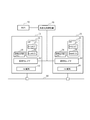
- a system according to the present invention includes an operation system 101 for executing processing, a standby system 102 capable of scaling (at least one of scale-up and scale-down), and the scaling (scale-up or scale-down). And a control device (control means) 103 that controls system switching using the standby system 102 as a new operating system.
- the control device 103 instructs the standby system 102 to perform scaling (scale up or scale down) according to the processing load of the operation system 101 (or an instruction / setting from a maintenance device not shown). To do.
- the control device 103 receives a notification of completion of scaling (scale-up or scale-down) from the standby system 102 that has completed the scaling (scale-up or scale-down), and receives the scaling (scale-up or scale-down) of the standby system 102 May be configured as a new operating system, and the switching of the system with the operating system 101 before the system switching as a new standby system may be controlled.
- the control device 103 controls the new standby system (the original active system, which becomes a new standby system by switching the system) with respect to the new active system (the original scale-up or scale-down before the system switch). It may be configured to control to scale up or scale down as in the standby system.
- the control device 103 needs to scale up based on, for example, the detection result of the processing load of the active system 101 before system switching, or based on, for example, a setting or instruction (for example, input of a scale-up instruction) from the maintenance device.
- the standby system 102 is instructed to switch to the active system.
- the system 101 (original active system 101) that newly becomes a standby system by system switching may impose processing restrictions, for example, on the system 102 (original standby system 102) that becomes the new active system. Good.
- the control device 103 may be configured to release the processing restriction imposed on the system 102 that newly becomes the active system upon receiving a scale-up completion notification from the system 101 that newly becomes the standby system.
- the control device 103 performs scale-down based on the result of detecting that there is a margin in the processing of the original active system 101 before system switching, or based on settings and instructions (for example, scale-down instruction input) from the maintenance device. Is determined, the processing restriction is imposed on the active system 101 before the system switchover, and the standby system 102 before the system switchover is instructed to execute the scale down.
- the control device 103 receives a scale-down completion notification from the standby system 102 that has completed the scale-down, the control device 103 performs system switching and sets a new operation system. The new active system takes over the processing restrictions imposed on the original active system 101 before the system switchover from the original active system 101.
- control apparatus 103 instructs the new standby system 101 (original operation system 101) to perform scale down and receives a notification of completion of scale down from the new standby system 101
- the control apparatus 103 establishes a new operation system by system switching.
- the processing restriction imposed on the system 102 (the original standby system 102) (the processing restriction inherited from the original operation system 101) may be released.
- the scale-up and scale-down can be performed by increasing / decreasing the virtual hardware resources such as virtual CPUs (virtual CPU Central CPU Processing CPU Unit) assigned to the active and standby virtual machines (VMs). Good.
- the scale-up is a technique for increasing the processing performance by adding a server CPU or memory allocated to the virtual machine (VM).
- Scale-down is a technology that lowers the processing performance by reducing the CPU and memory of a server allocated to a virtual machine (VM).
- the scale-up (scale-down) improves (reduces) the processing performance of the computer alone by spec-up (spec-down) the CPU, memory, etc. in the computer such as a server.
- Scale-out improves (reduces) the processing performance of the system by increasing (decreasing) the number of computers such as servers. Improving (decreasing) the processing performance of the virtualization system by adding or removing virtual machines (VMs) on the server corresponds to scale-out (scale-in) when focusing on the virtual machines (VM). As a result, since the processing performance of the server alone is improved (reduced), it can be said that the server is scaled up (equivalent).
- the control device 103 scales up or down the standby system 102 that is the system switching destination of the active system in accordance with the congestion or margin of the processing of the active system 101 that performs session processing (for example, call processing). May be instructed.
- Each virtual machine (VM) whose application running on the virtual machine (VM) is an active system and a standby system may be mounted on different servers, or may be mounted on the same server. Also good.
- an application running on a virtual machine (VM) is configured so that each virtual machine (VM) that is an active system and a standby system is mounted on the same server, multiple virtual machines (operating on the virtual machine) of the server
- One or more virtual machines (applications running on virtual machines) as the active system, and one or more virtual machines (applications running on the virtual machines) as standby systems It is good also as a structure.
- the server includes a virtual network function (Virtual Network Function: VNF) on the virtual machine, and an NFVI (Network Functions Virtualization Infrastructure) that forms the execution base (virtualization base) of the VNF.
- VNF Virtual Network Function
- NFVI Network Functions Virtualization Infrastructure
- the server may be configured to include an open stack agent or an extension thereof as a server agent.
- the active system and the standby system may be configured in units of virtual deployment units (VDUs) on NFVI.
- VDUs virtual deployment units
- FIG. 2A and 2B show virtual CPUs (virtual central processing units: vCPUs) in virtual machines on the active system (ACT system) server 1 and the standby system (SBY system) server 2 before system switching. )
- the active and standby servers 1 and 2 each include a virtual machine (VM) that is virtualized via a hypervisor (HV) (not shown), and the virtual machine includes at least one virtual CPU. (VCPU).
- VM virtual machine
- HV hypervisor
- FIG. 2 shows virtual CPUs (vCPUs) allocated to one virtual machine (VM) in each of the servers 1 and 2 (virtual CPUs can be allocated up to the maximum number that can be allocated to virtual machines. Is).
- One process is assigned to each virtual CPU (vCPU).
- the number of threads that can be processed in parallel in the virtual machine (VM) is proportional to the number of virtual CPUs.
- one process is assigned to one virtual CPU (vCPU) for simplicity, but a plurality of processes may be assigned to one virtual CPU (vCPU).
- a hypervisor, a virtual machine (VM), a guest OS (Operating System), and the like on the server are omitted.
- the control device (103 in FIG. 1) for controlling the switching of the system is also omitted.
- the standby system (SBY) in FIG. 2B is scaled up compared to the operational system (ACT) that executes the process (eg, session process) in FIG. 2A (in this case, Two virtual CPUs (vCPUs) are added (hotadded).
- Hotadd is a function for dynamically adding a CPU and memory to a running system. For example, in hot add, a device (vCPU in this example) is added without stopping the virtual machine (VM), and the added device (vCPU) is recognized by the virtual machine (VM).
- the standby system (SBY) in FIG. 2B is configured as a hot standby system, a process is already assigned to each virtual CPU (vCPU), and the active system (in FIG. 2A) ( ACT) is assumed to be synchronized with the data. Since the standby system (SBY) in FIG. 2B does not directly affect session processing or the like, it is possible to start up a virtual machine (VM) (restart the guest OS or process).
- VM virtual machine
- session start / end management, etc. is a session management function (HTTP (Hyper) in the SIP (Session Initiation Protocol) protocol or J2EE (Java (registered trademark) 2 Platform, Enterprise) Edition) (servlet). Text Transport Protocol) session).
- HTTP HyperText Transfer Protocol
- the standby system in FIG. 2B becomes a new active system (ACT) (FIG. 2 ( D))
- the active system in FIG. 2A becomes a new standby system (SBY) (FIG. 2C).
- the processing performance can be scaled up by taking over the processing of the operating system 1 (FIG. 2A) before system switching.
- the dynamic scale-up and scale-down of the virtual machine includes the increase / decrease in the number of virtual CPUs (vCPUs), the number of CPU cores, memory such as RAM (Random Access Memory), and disks (HDD (Hard Disk Drive)).
- a network interface controller Network Interface Controller: NIC
- the number of virtual CPUs (the number of cores), the storage capacity of the virtual memory, the storage area (capacity) of the virtual disk, the number of virtual NICs (Network Interface Controller), etc. should be supported by at least one increase / decrease May be.
- FIGS. 3A and 3B schematically illustrate virtual CPUs (vCPUs) in virtual machines on the active system (ACT system) server 1 and the standby system (SBY system) server 2 before system switching. It shows.
- the standby system (SBY) server 2 in FIG. 3B two virtual CPUs (vCPUs) are deleted from the active system (ACT) server 1 in FIG.
- the process assigned to the virtual CPU (vCPU) is also released from the assignment to the virtual CPU (vCPU).
- FIG. 3B becomes a new active system (FIG. 3D).
- the active system in FIG. 3A becomes a new standby system (FIG. 3C).
- ACT original standby system 2
- FIG. 3 (D) the processing performance scale-down is maintained while taking over the processing of the active system 1 (FIG. 3 (A)) before system switching. It becomes possible.
- the new standby system in FIG. 3C is scaled down (hotdel) as in the new operational system in FIG. 3D, session processing (call No problem occurs because it does not affect the processing, etc.).
- Hotdel is a function that dynamically deletes a CPU and memory from a running system.
- the device for example, vCPU
- VM virtual machine
- ⁇ Comparative example> 4A and 4B are diagrams for explaining the scale-up and scale-down of a virtual machine in a comparative example (example in which the present invention is not applied: ACT and SBY are not used).
- FIG. 4B is a diagram schematically illustrating a virtual machine of the server 1B that is scaled up by adding a virtual CPU (vCPU) (hotadd) to the server 1A of FIG. 4A.
- the server 1B only adds a virtual CPU (vCPU) (Hotadd) and cannot effectively use resources. That is, until a process is assigned to the added virtual CPU (vCPU) and the process is activated, the added virtual CPU (vCPU) or the like does not contribute to the improvement of the processing capability of the server 1B.
- FIG. 4D schematically shows a virtual machine (vCPU) of the server 1D scaled down by removing a virtual CPU (vCPU) from the server 1C of FIG. 4C (Hotdel).
- FIG. In the server 1C processing is performed by six virtual CPUs. However, as shown in FIG. 4D, when two virtual CPUs (vCPUs) are reduced, processes and threads are allocated to the virtual CPUs (vCPUs).
- vCPUs virtual CPUs
- vCPUs virtual CPUs
- vCPUs virtual CPUs
- a failure may occur in a process assigned to the virtual CPU. Due to this process failure, for example, a session that has been performed in the virtual machine on the server 1C may fail to be taken over (maintained) to the virtual machine on the server 1D.
- the increased virtual hardware resources contribute to the improvement of the processing performance.
- a delay occurs (it takes time to assign a process to a virtual CPU, etc.), and the resource cannot be used efficiently.
- a process failure occurs in the scale-down of the virtual machine (VM) and the takeover (maintenance) of the session may fail. It also leads to.
- FIG. 5 is a diagram illustrating an example of a system configuration of the present embodiment.
- an application (software) (Application: APL) 17 running on a virtual machine (VM) 15 on a server (Physical Machine (PM)) 11 constitutes an operation system (ACT system).
- the server 11 includes computing hardware (for example, CPU core), storage hardware (HDD, RAM (Random Access Memory), etc.), hardware (Hardware: HW) resources 13 such as network hardware,
- a virtual layer 12 such as a hypervisor that constitutes a virtualization function, a virtual hardware resource 14 obtained by virtualizing a hardware resource 13 such as a virtual CPU (vCPU), and a virtual machine 15 are provided.
- an application 17 (ACT system) is executed by the guest OS 16, and, for example, a virtualized network function (VNF) is realized in software.
- VNF virtualized network function
- the configuration includes a plurality of virtual machines 15 (two in FIG. 5), but the number of virtual machines 15 is not limited to the configuration of FIG.
- the virtual hardware resources 14 and 24 such as virtual CPUs (vCPUs) are arranged on the virtualization layers 12 and 22 in parallel with the virtual machines 15 and 25 for convenience of explanation. Has been.
- the application (software) (APL) 27 running on the virtual machine (VM) 25 on the server (physical machine) 21 constitutes a standby system (SBY system).
- the basic configuration of the server 21 is the same as that of the active server 11.
- virtual hardware resources such as a virtual CPU (vCPU) allocated to the standby system side.
- vCPU virtual CPU
- a process is allocated to the added virtual CPU (vCPU) (see FIG. 2B).
- the process is allocated to the virtual CPU (vCPU) of the virtual machine to be removed. Is released, virtual hardware resources such as a virtual CPU (vCPU) to be reduced are reduced.
- EMS Electronic Management System: element management system
- element management system 10 is a maintenance management system, and manages, sets, and maintains a virtual machine, for example.
- the EMS 10 communicates with a virtualization control device (also referred to as “virtualization infrastructure”) 20.
- virtualization control device also referred to as “virtualization infrastructure”
- the virtualization control device 20 monitors and controls the virtual machines 15 and 25 on the servers 11 and 21. That is, for example, the virtualization control device 20 communicates with the virtualization layers 12 and 22 such as the hypervisors of the servers 11 and 21, exchanges the configuration and state information of the virtual machine (VM), virtual It exchanges the configuration and status information of virtualized hardware resources such as virtual CPUs allocated to the machine, controls the placement and control of virtual machines, system switching, and communicates with the EMS 10.
- the servers 11 and 21 are connected by a network 30 such as a LAN (Local Area Network).
- the server on which the application on the virtual machine is newly set as the active system When taking over the IP address of the server having the original operation system application (before system switching), for example, the alias IP address may be taken over (the server 11 and the server 21 have the same alias IP address).
- the server LAN adapter may be switched.
- a system that does not take over the IP address at the time of system switching may be used.
- the active system and standby system applications (applications on the virtual machine) 17 and 27 operate on different servers (physical machines) 11 and 21, but may be the same server. .
- One or a plurality of combinations of a plurality of applications respectively running on a plurality of virtual machines on one server (physical machine) may be used as an active system, and the rest may be used as a standby system. All applications running on multiple virtual machines on one server (physical machine) are all active, and multiple applications running on multiple virtual machines on another server (physical machine) are all active. It may be a standby system.
- the server that operates the virtual machine on the server is also referred to as an “active server”.
- the standby server is also referred to as a “standby server” for the application running on the virtual machine on the server.
- FIG. 11 quotes Chapter 7 of Non-Patent Document 1 and FIG. 4 and shows an NFV reference architecture framework (NFV reference architectural framework) defined by NFV (Network Function Virtualization) ISG (Industry Specification Groups). ing.
- NFV reference architectural framework defined by NFV (Network Function Virtualization) ISG (Industry Specification Groups).
- VNFs Virtual Network Functions
- the VNFs 1 to 3 correspond to, for example, applications that operate on the virtual machine (VM) in FIG.
- the VNFs 1 to 3 are network functions (for example, MME (Mobility Management Entity) or S-GW (Serving Gateway)), N-GW (Serving Gateway), EPC (Evolved Packet Core) which is the core network of LTE (Long Term Evolution) network. Etc.) may be realized by software (virtual machine).
- EMS lement Management System
- NFVI Network Functions Virtualization Infrastructure
- server the hardware resources of the physical machine (server) such as computing, storage, and network functions (13 and 23 in FIG. 5).
- virtual hardware resource As a virtual hardware resource (14, 24 in FIG. 5) such as virtualized computing, virtual storage, and virtualized network that is virtualized by a virtualization layer (12, 22 in FIG. 5). It is a base that can be handled.
- NFV MANO includes an NFV orchestrator (NFV-Orchestrator: NFVO), a VNF manager (VNF-Manager: VNFM), and a virtualized infrastructure manager (Virtulated Infrastructure Manager: VIM).
- NFV-Orchestrator NFVO
- VNF-Manager VNFM
- VIM Virtualized Infrastructure Manager
- NFV-Orchestrator performs orchestration and management of NFVI and VNF, and realizes network services on NFVI (resource allocation to VNF, management of VNF (auto healing, auto scaling) ) VNF lifecycle management (life cycle management))).
- VNFM The VNF-Manager (VNFM) performs VNF lifecycle management (instantiation, update, search, scaling, healing, termination, etc.).
- Virtualized Infrastructure Manager controls NFVI through the virtualization layer (computing, storage, network resource management, NFVI execution monitoring of VNF, monitoring of resource information, etc.).
- NSD Network Service Descriptor
- VLD Virtual Link Descriptor
- VNFFGD VNF Forwarding Graph Descriptor
- VNFD VNF Descriptor
- PNFD Physical Network Function Descriptor
- KPI Key Performance Indicators
- OSS Operations Support Systems
- BSS Business Support Systems
- information systems devices, software, mechanisms, etc. that are used by carriers (carriers) for billing usage charges, billing, customer service, and the like.
- Os-Ma is a reference point between OSS (Operation Service Systems) / BSS (Business Services Systems) and NFV-MANO, and is related to network service life cycle management requests, VNF life cycle management requests, and NFV-related items. Used for status information transfer, policy management information exchange, etc.
- the reference point Or-VNFm is used for resource-related requests (authentication, reservation, allocation, etc.) by the VNF-Manager (VNFM), transfer of configuration information to the VNFM, and collection of VNF status information.
- the reference point Vi-VNFm is used for resource allocation requests from VNFM, virtual resource configuration and status information exchange, such as NFVI resource search and allocation / release.
- the reference point Or-Vi is used for exchanging configuration information and status information of virtual resources such as reservation / release, allocation / release / update of NFVI resources from NFVO, and addition / deletion / update of NFVI software images.
- the reference point Ve-VNFm is used for exchanging VNF life cycle management requests, configuration information, and status information between EMS and VNFM and between VNFM and VNFM.
- the reference point Nf-Vi is a virtual resource allocation for virtual resource allocation requests such as VM allocation, VM resource allocation update, VM migration, VM termination, and creation / deletion of connection between VMs, together with an instruction for compute / storage resources. It is used to transfer the status information of the generalized resources and to exchange the configuration and status information of the hardware resources.
- the reference point Se-Ma is used for searching information models of NFV deployment template and NFV infrastructure.
- the reference point Vi-Ha interfaces the virtualization layer and hardware resources to generate a VNF execution environment and collects state information for VNF management.
- Reference point Vn-Nf represents an execution environment provided to VNF by NFVI (for details, see Non-Patent Document 1).
- FIG. 6 is a diagram schematically illustrating control functions related to scale-up and scale-down of the virtualization control device 20 and the servers 11 and 21 of FIG.
- the server 11 includes a processing load monitor unit 111, a system switching unit 112, a processing restriction control unit 113, a scale up execution unit 114, a scale down execution unit 115, and a communication control unit 116.
- the processing load monitoring unit 111, the system switching unit 112, and the processing restriction control unit 113 are realized by, for example, processing of an application operating on the virtual machine (VM) 15 in FIG.
- the scale-up execution unit 114 and the scale-down execution unit 115 are realized by the processing of the virtualization layer 12 (hypervisor) in FIG.
- the processing load monitor unit 111 monitors the processing load of the virtual machine and detects processing congestion and processing margin. When detecting the processing congestion and the processing margin, the processing load monitoring unit 111 notifies the EMS 10 via the transmission unit (not shown) of the communication control unit 116.
- the system switching unit 112 executes system switching.
- the system switching unit 112 switches the application 17 of the local server 11 to the standby system and switches the application 27 of the server 21 to the active system. To instruct.
- the system switching unit 112 determines that the application 27 on the virtual machine 25 is based on an instruction from the system switching unit of the active server 21. 11 applications 17 are switched to the operational system.
- the system switching unit 112 performs various settings such as processing from the active application 27 running on the virtual machine 25, execution environment, and the like. Controls takeover of the client.
- the processing restriction control unit 113 instructs the application 27 to newly become the active system from the standby system to limit processing. After the scale-up on the own server 11 side is completed, an instruction to cancel the processing restriction is given to the application 27 that becomes a new active system.
- the processing restriction control unit 113 sends a processing restriction removal request from the virtualization control device 20 via the communication control unit 116. Upon receipt, the processing restriction on the application 17 on the server 11 is released.
- the scale-up execution unit 114 When the scale-up execution unit 114 receives a scale-up request from the virtualization control device 20 via the communication control unit 116 (transmission unit not shown), the virtual hardware resource (for example, virtual CPU) allocated to the virtual machine (FIG. 5). 14). The scale-up execution unit 114 controls process allocation to the added virtual CPU. The scale-up execution unit 114 notifies the virtualization control device 20 of the completion of the scale-up via the communication control unit 116 after the scale-up is completed.
- the virtual hardware resource for example, virtual CPU
- the scale-down execution unit 115 When the scale-down execution unit 115 receives a scale-down request from the virtualization control device 20 via the communication control unit 116, the scale-down execution unit 115 reduces the virtual hardware resources (for example, virtual CPU) (14 in FIG. 5) allocated to the virtual machine. Set up. At that time, the scale-down execution unit 115 releases the allocation of the process to the virtual CPU to be deleted. The scale-down execution unit 115 notifies the virtualization control device 20 of the completion of the scale-down via the communication control unit 116 after the scale-down is completed.
- virtual hardware resources for example, virtual CPU
- the processing load monitoring unit 111, the system switching unit 112, and the processing restriction control unit 113 are realized by, for example, processing of an application (APL) 17 that operates in the virtual machine (VM) 15 in FIG.
- APL application
- the scale-up execution unit 214 and the scale-down execution unit 215 may be realized by the processing of the virtualization layer 12 (hypervisor (HV)) in FIG.
- HV hypervisor
- a management OS Operating System
- the management OS is used.
- the above-described units may be mounted on the virtual machine of the management OS.
- the server 21 has the same configuration as the server 11.
- the processing load monitoring unit 211, the system switching unit 212, and the processing restriction control unit 213 are realized by, for example, processing of an application (APL) 27 that operates on the virtual machine (VM) 25 in FIG. 5.
- the scale-up execution unit 214 and the scale-down execution unit 215 may be realized by the processing of the virtualization layer 22 (hypervisor (HV) in FIG. 5.
- Communication control units 116 and 216 transmitting unit and receiving unit (not shown)).
- the communication control unit, the virtualization layer, the VM, and the like of the servers 11 and 21 realize part or all of the respective functions by a program executed by a processor (CPU) (not shown) that constitutes the servers 11 and 21. May be.
- the processor reads a program stored in a memory (semiconductor memory, HDD, etc.) (not shown) built in the server 11 or 21 or connected to the server 11 or 21 into the main memory and executes the program (instruction).
- a memory semiconductor memory, HDD, etc.
- the virtualization control device 20 includes a sequence control unit 201, a scale-up control unit 202, a scale-down control unit 203, a system switching control unit 204, a communication control unit 205 that controls communication with the EMS 10, and the server 11. , 21 is provided with a communication control unit 206 for controlling communication with.
- the communication control units 205 and 206 are provided separately, but it goes without saying that these may be used as one communication control unit.
- the sequence control unit 201 activates the scale-up control unit 202, the scale-down control unit 203, and the system switching control unit 204, and controls the scale-up and scale-down by providing necessary information and the like. Controls the sequence operation.
- the sequence control unit 201 controls the scale-up sequence or the scale-down sequence when receiving notification of processing congestion of the virtual machine or processing margin from the active server of the servers 11 and 21 via the communication control unit 206. To do.
- the sequence control unit 201 activates the scale-up control unit 202.
- the scale-up control unit 202 instructs the server to be scaled up (its hypervisor (HV)) to scale up, such as adding a virtual CPU.
- the scale-up control unit 202 may instruct information such as the number of additional virtual CPUs to the scale-up unit of the server.
- the sequence control unit 201 activates the system switching control unit 204 when receiving, for example, a scale-up completion notification from an application switched from the active system to the standby system via the communication control unit 206.
- the system switching control unit 204 instructs the system switching to the operational server (the operational system application) via the communication control unit 206 by the application running on the virtual machine.
- the active application that has received the system switching instruction from the virtualization control device 20 makes a transition to the standby system, and the application running on the virtual machine becomes the standby server (the standby application). Instruct the transition to the active system.
- sequence control unit 201 When the sequence control unit 201 receives the completion of the system switching from the server application, the sequence control unit 201 notifies the EMS 10 via the communication control unit 205 of a scale-up completion notification.
- the sequence control unit 201 activates the scale down control unit 203.
- the scale-down control unit 203 instructs the scale-down target server (hibervisor (HV)) to perform scale-down such as reduction of virtual CPUs. Note that the scale-down control unit 203 may instruct the server scale-down unit (hypervisor (HV)) information such as the number of virtual CPUs to be removed.
- HV scale-down target server
- HV hypervisor
- the sequence control unit 201 activates the system switching control unit 204 when the application running on the virtual machine receives a scale-down completion notification from the standby server via the communication control unit 206.
- the system switching control unit 204 instructs the system switching to the operational server (the relevant operational system application) via the communication control unit 206 by the application running on the virtual machine.
- the active application that has received the system switching instruction from the virtualization control device 20 transitions to the standby system, and further transitions to the active system with respect to the (original) standby application before switching. Instruct.
- sequence control unit 201 when the sequence control unit 201 receives a system switching completion from an application switched from the active system to the standby system, the sequence control unit 201 notifies the EMS 10 via the communication control unit 205 of a scale-down completion notification.
- each of the units 201 to 206 of the virtualization control device 20 realizes part or all of the respective functions by a program executed by a processor (CPU) (not shown) constituting the virtualization control device 20. May be.
- the processor reads a program stored in a memory (semiconductor memory, HDD, etc.) (not shown) that is built in the virtualization control device 20 or connected to the virtualization control device 20 into the main memory and loads a program (command).
- each function is realized in software or in cooperation with software and hardware.
- FIG. 7 is a diagram schematically illustrating an example of a scale-up sequence in the system of the embodiment described with reference to FIGS. 5 and 6.
- physical servers 11 and 21 correspond to the servers (physical machines: PM) 11 and 21 in FIGS. 5 and 6. Note that the physical servers 11 and 21 are for clearly indicating that the server is a physical machine (PM) (devices (units) different from the servers 11 and 21). .
- the virtualization layers 12 and 22 of FIG. 6 are represented by hypervisors (HV) 12 and 22, respectively.
- VM ACT represents an operation (ACT) application on the virtual machine (VM)
- VM SBY represents a standby (SBY) application on the virtual machine (VM).
- the application may be an NFV VDU (Virtualization Deployment Unit) or the like.
- VM ACT may be the active VM
- VM SBY may be the standby VM.
- FIG. 7 a number (step number) is added to a typical sequence for explanation. The same applies to FIGS. 8 to 10 described later.
- the processing load monitor 111 of the server 11 detects processing congestion of an application running on the virtual machine (S1).
- the processing load monitoring unit 111 of the server 11 notifies the virtualization control device 20 of congestion detection (S2).
- the sequence control unit 201 notifies the EMS of the congestion of the application on the server 11 and notifies the start of scale-up (S3).
- the sequence control unit 201 of the virtualization control device 20 activates the scale-up control unit 202, and the scale-up control unit 202 uses the standby server (SBY) server 21 (hyperpies ( HV)) is instructed to scale up (Hotadd) (S4).
- SBY standby server
- HV hyperpies
- Hotadd scale up
- the scale-up execution unit 214 of the server 21 Upon receiving the scale-up instruction, the scale-up execution unit 214 of the server 21 (for example, mounted in the hypervisor (HV)) executes hot add (Shotadd) (S5), and the standby system (SBY) application 27 operates.
- a virtual CPU (vCPU) or the like to be allocated to the virtual machine 25 is added (vCPU is added), a process is allocated to the virtual CPU (vCPU), and a scale-up completion notification (Hotadd completion notification) is sent to the virtualization controller 20. (S6).
- sequence control unit 201 of the virtualization control device 20 receives a notification of completion of the scale-up (hotadd)
- the sequence control unit 204 starts the system switching control unit 204, and the system switching control unit 204 operates an application running on the virtual machine.
- a system switching instruction is transmitted to the system switching unit 112 (for example, an application on the VM) of the server 11 which is the system (ACT) (S7).
- the application system is switched between the server 11 and the server 21 (S8).
- the system switching unit 112 of the server 11 in which the application 17 operating on the virtual machine 15 is the active system (ACT) sets the application 17 as the standby system (SBY), and the application 27 operating on the virtual machine 25 is the standby system (ACT).
- the server 21 which is SBY is instructed to transition to the active system (ACT).
- the system switching unit 212 of the server 21 whose application 27 running on the virtual machine 25 is the standby system (SBY) sets the application 27 to the active system (ACT) (switches from the standby system to the active system). ).
- the server 11 (the application 17) in which the application 17 operating on the virtual machine 15 is changed from the active system (ACT) to the standby system (SBY) by the system switching of the application is switched over to the virtualization control device 20. Completion is notified (S9).
- the sequence control unit 201 of the virtualization control device 20 that has received the notification of system switching completion transmits a scale-up completion notification to the EMS 10 (S10).
- FIG. 8 is a diagram schematically illustrating an example of a scale-down sequence in the system of the embodiment described with reference to FIGS. 5 and 6.
- VM ACT represents an operation (ACT) application on the virtual machine (VM)
- VM SBY represents a standby (SBY) application on the virtual machine (VM).
- ACT operation
- SBY standby
- the processing load monitor unit 111 of the server 11 detects the processing margin of the virtual machine (S21).
- the processing load monitoring unit 111 of the server 11 determines that the scale down is possible due to the processing margin, and notifies the virtualization control device 20 (S22).
- the sequence control unit 201 notifies the EMS 10 of the start of the scale-down in the server 11 (S23).
- the sequence control unit 201 of the virtualization control device 20 activates the scale-down control unit 203, and the scale-down control unit 203 includes the server 21 (hyper-piezer) whose application 27 running on the virtual machine 25 is a standby system (SBY). (HV)) is instructed to scale down (Hotdel) (S24).
- server 21 hyper-piezer
- SBY standby system
- HV standby system
- the scale-down execution unit 215 for example, hypervisor (HV)
- HV hypervisor
- the scale-down execution unit 215 executes hot del (Hotdel) (S25), and enters the virtual machine 25 in which the standby system (SBY) application 27 is running.
- a virtual CPU (vCPU) or the like to be allocated is reduced, the process allocation is canceled, and a scale-down (Hotdel) completion notification is transmitted to the virtualization controller 20 (S26).
- sequence control unit 201 of the virtualization control device 20 When the sequence control unit 201 of the virtualization control device 20 receives a notification of completion of the scale-down (hotdel), the sequence control unit 204 activates the system switching control unit 204, and the system switching control unit 204 operates on the virtual machine 15 on the server 11. A system switching instruction is transmitted to the application 17 (S27).
- the application system is switched between the server 11 and the server 21 (S28).
- the system switching unit 112 of the server 11 in which the application 17 on the virtual machine 15 is the active system (ACT) makes the application 17 a new standby system (SBY), and the application 27 on the virtual machine 25 is the standby system (SBY).
- the server 21 is instructed to transition to an active system (ACT).
- the system switching unit 212 of the server 21 sets the application 27 to the active system (ACT) (switches from the standby system to the active system).
- the server 11 in which the application 17 on the virtual machine (VM) 15 becomes the standby system (SBY) due to the system switching notifies the virtualization control apparatus 20 of the system switching completion (S29).
- the sequence control device 201 of the virtualization control device 20 that has received the notification of system switching completion transmits a scale-down completion notification to the EMS 10 (S30).
- FIG. 9 is a diagram for explaining in detail an example of the sequence of system switching execution (S8) in FIG.
- sequences (step numbers) S1 to S7 are the same as those in FIG. 7 receives a notification of congestion detection of the virtual machine in the physical server 11, and sends a scale-up (hotadd) request from the virtualization control device 20 to the physical server 21 in the standby system (SBY). However, in response to a request from a maintenance person (for example, EMS 10), a scale-up (hotadd) request may be transmitted from the virtualization control device 20 to the standby (SBY) physical server 21. Good.
- a maintenance person for example, EMS 10
- the system switching unit 112 of the server 11 whose application 17 is the active system (ACT) sets the application 17 to the standby system (SBY) (S8-1).
- the virtualization control device 20 communicates with the hypervisors (HV) of the servers 11 and 21.
- SBY standby system
- the current application 17 has the active system (ACT) and the standby system (SBY).
- the server 11 takes over the execution environment of the application 17 that has been operating as the active system (ACT), the setting parameter information, the takeover information such as data, etc., to the application 27 that newly becomes the active system (ACT).
- the information may be saved in a predetermined storage area, and the application 27 may be transferred to the server 21 that newly becomes an active system (ACT).
- the system switching unit 212 sets the operation system (ACT) (S8-3).
- the application 27 of the server 21 that has newly become an active system (ACT) transmits a notification of ACT transition completion to the server 11 (S8-4).
- the processing restriction control unit 213 of the server 21 restricts the call processing performed in the virtual machine (S8-6). This limits the call processing volume during system switching so that the increased call processing is not accepted until both the standby system (SBY) scale-up and the active system (ACT) scale-up are completed. Is.
- the system switching unit 112 In the server 11 that has received the call processing restriction request completion (the application 17 becomes a new standby system), the system switching unit 112 notifies the virtualization control device 20 of the system switching completion (S8-8).
- the application 17 on the virtual machine 15 transmits a scale-up (hotadd) request to the standby system (SBY) server 11 (hypervisor (HV)) (S8-9).
- SBY standby system
- HV hypervisor
- data replication is performed in an active system (ACT) and a standby system.
- ACT active system
- standby system for example, data replication is performed in an active system (ACT) and a standby system.
- ACT active system
- the scale-up (hotadd) is also performed for the server 11 (hypervisor (HV)) in which 17 becomes the standby system (SBY).
- the scale-up execution unit 114 of the server 11 adds (hotadds) a virtual CPU to be allocated to the virtual machine (VM) 15 in which the application 17 operates (S8-10).
- VM virtual machine
- S8-10 virtual machine
- the scale-up execution unit 114 of the server 11 transmits a scale-up (hotadd) necessary completion notification to the virtualization control device 20 (S8-11).
- the virtualization control device 20 transmits a call processing restriction release request to the server 21 (S8-12).
- the processing restriction control unit 213 of the server 21 releases the call processing restriction (S8-13).
- ACT new active system
- SBY new standby system
- the new active system is allowed to accept call processing for the scale-up (addition).
- the processing restriction control unit 213 of the server 21 transmits a call processing restriction release completion notification to the virtualization control device 20 (S8-14).
- the virtualization control device 20 that has received the call processing restriction release completion notification transmits a scale-up completion notification to the EMS 10 (S20).
- the virtualization control device 20 transmits a call processing restriction release request to the server 21 (the application that has become the active system on the virtual machine) (S8-12).
- the server 11 that has completed the scale-up (Hotadd) may transmit a call processing restriction release request to the server 21.
- the server 21 that has canceled the call processing restriction transmits a call processing restriction release completion notification to the server 11, and the server 11 that has received the call processing restriction release completion notification sends a system switching completion notification in accordance with S9 of FIG.
- the virtualization control device 20 that has transmitted to the virtualization control device 20 and received the system switching completion notification transmits a scale-up completion notification to the EMS 10.
- FIG. 10 is a diagram for explaining in detail an example of the sequence of system switching execution (S28) in FIG.
- steps S24 to S27 and S30 correspond to S24 to S27 and S30 of FIG. 8, respectively.
- the server 11 detects the processing margin and transmits a determination result that the scale down is possible to the virtualization control device 20, and the virtualization control device 20 instructs the server 21 to scale down.
- the EMS 10 of FIG. 7 instructs the virtualization control device 20 to request a scale down (S20A).
- the virtualization control device 20 Upon receiving the scale-down request, the virtualization control device 20 causes the application 17 running on the virtual machine (VM) 15 to transmit a call processing restriction release request to the active (ACT) server 11 (S20B).
- the processing restriction control unit 113 of the server 11 restricts call processing to be processed by the virtual machine (VM) (S20C). This restricts (reduces) the call processing in advance so that the call processing does not get congested after receiving the amount of call processing before the scale down.
- the server 11 transmits a call processing restriction completion notification to the virtualization control device 20 (S20D).
- the virtualization control device 20 scales down the application running on the virtual machine (VM) to the standby (SBY) server 21 (hypervisor (HV)) (Hotdel: Hotdel). ) Is requested (S24).
- the scale-down execution unit 215 of the server 21 reduces the number of virtual CPUs (vCPUs) that are allocated to the virtual machines in the standby system (SBY) by applications running on the virtual machines (VMs) (S25). In this case, it goes without saying that the virtual memory and virtual storage allocated to the virtual machine, the bandwidth of the virtual network, the number of installed virtual NICs, etc. may be reduced (reduced).
- the scale-down execution unit 215 of the server 21 whose application running on the virtual machine (VM) is the standby system (SBY) allocates a process to the virtual CPU (vCPU) when the virtual CPU (vCPU) is reduced. After canceling, the virtual CPU (vCPU) is reduced.
- SBY standby system
- the server 21 transmits a scale-down completion notification (hotdel: Hotdel completion notification) to the virtualization control device 20 (S26).
- hotdel Hotdel completion notification
- the virtualization control device 20 instructs the server 11 to switch the system (S27). *
- the system switching unit 112 of the server 11 Upon receiving the system switching instruction from the virtualization control device 20, the system switching unit 112 of the server 11 sets the application 17 running on the virtual machine (VM) 15 of the server 11 to the standby system (SBY) (S28-). 1).
- the server 11 transmits a transition request (ACT transition request) to the operational system (ACT) of the application 27 running on the virtual machine (VM) 25 to the server 21 (S28-2).
- ACT transition request a transition request
- ACT operational system
- VM virtual machine
- the system switching unit 212 of the server 21 sets the application 27 running on the virtual machine (VM) 25 of the server 21 to the active system (ACT) (S28-3).
- the application 27 of the server 21 that newly becomes the active system (ACT) takes over the operating environment, setting information, and the like of the application 17 of the server 11 that was the active system (ACT) before system switching.
- the call processing restriction requested by the virtualization control device 20 for the application 17 on the virtual machine 15 before the system switchover is newly set to the active system (ACT). To the application 27 on the virtual machine.
- the server 21 in which the application 27 on the virtual machine (VM) 25 has newly become an operational system (ACT) transmits an ACT transition completion notification to the server 11 (S28-4).
- the server 11 Upon receiving the ACT transition completion notification, the server 11 notifies the server 21 that the application 17 on the virtual machine 15 of the server 11 has completed the transition to the standby system (S28-5).
- the server 11 notifies the virtualization control device 20 of the completion of system switching (S28-6).
- the application 17 running on the virtual machine (VM) 15 transmits a scale-down (hotdel) request to the standby system (SBY) server 11 (S28-7).
- SBY standby system
- data replication is performed in an active system (ACT) and a standby system.
- ACT active system
- SBY standby system
- the scale-down execution unit 114 (for example, implemented in the hypervisor (HV)) of the server 11 is a virtual that the application 17 running on the virtual machine (VM) 15 assigns to the virtual machine 15 that has become a standby system (SBY).
- the CPU is removed (Hotdel) (S28-8).
- the scale-down execution unit 114 of the server 11 cancels the allocation of the process to the virtual CPU, and then reduces (hotdels) the virtual CPU.
- the server 11 transmits a scale-down (Hotdel) request notification to the virtualization control device 20 (S28-9).
- Hotdel scale-down
- the virtualization control device 20 transmits a call processing restriction release request to the server 21 (S28-10).
- the processing restriction control unit 213 of the server 21 releases the call processing restriction (S28-11). Call processing by the processing restriction control unit 213 in the new operation system after the scale-down of the applications (new operation system (ACT) and new standby system (SBY)) running on the virtual machine (VM) is completed. Remove the restriction.
- the server 21 transmits a call processing restriction release completion notification to the virtualization control device 20 (S28-12).
- the virtualization control device 20 that has received the call processing restriction release completion notification transmits a scale-down completion notification to the EMS 10 (S30).
- the virtualization control device 20 transmits a call processing restriction release request to the server 21 (S28-10), but the server 21 sends a call processing restriction release completion notice to the server 11 ,
- the server 11 transmits a system switching completion notification to the virtualization control device 20 according to the sequence number 9 in FIG. 8, and the virtualization control device 20 that has received the system switching completion notification sends a scale-down completion notification to the EMS 10. You may make it transmit.
- call processing for example, VoIP (Voice over IP) call processing
- VoIP Voice over IP
- FIG. 12 is a diagram showing an example in which the above-described scale control by duplication of the present embodiment is applied to an NFV system.
- the open stack and the extension unit constitute the VIM of FIG.
- the orchestrator II that performs VNF life cycle management, configuration information management, status monitoring, and the like constitutes the VNFM of FIG.
- the orchestrator I in FIG. 12 includes an identity manager, a global resource orchestrator, a local resource orchestrator, an O & M integrated manager (O & M integrated manager), a template management, a service orchestrator, and the like. Details of the orchestrator I (corresponding to NVFO) are omitted. Regarding the configuration and function of NVFO, in addition to the related description in FIG. 11, non-patent document 1 and the like are appropriately referred to for details.
- Open Stack is an open stack -Nova (VM network resource control, etc.) / Glance (image management of guest OS, etc.), -Neutron (virtual network control and configuration management used by VM), -Includes Ceilometer (measurement and monitoring of NFVI resource usage, etc.).
- Nova / Glance performs control such as VM start / stop, VM migration, and management of VM resource information, for example.
- Neutron controls generation of a virtual network and attachment of a virtual network, for example.
- the Ceilometer controls VM resource usage status collection, notification policy management (notification from NFVO), notification to NFVO, and the like.
- the extension is not particularly limited, but for example, A physical machine (PM) controller that performs physical machine (PM) control and resource management; A virtual machine (VM) controller that performs placement control (PM selection, etc.) of the virtual machine (VM), A network (NW) controller that performs management control such as fault monitoring and resource management of the virtual network used by the virtual machine, -Monitoring of NFVI resources on the server (for example, physical machine (PM), virtual machine (VM) failure information collection, resource usage status collection, notification policy management (instruction from NFVO), notification to NFVO), etc. Includes resource monitoring to be performed.
- PM physical machine
- VM virtual machine
- NW network controller that performs management control
- management control such as fault monitoring and resource management of the virtual network used by the virtual machine, -Monitoring of NFVI resources on the server (for example, physical machine (PM), virtual machine (VM) failure information collection, resource usage status collection, notification policy management (instruction from NFVO), notification to NFVO), etc. Includes resource monitoring to
- the servers 11 and 21 in FIG. 12 correspond to the servers 11 and 21 in FIG.
- Each of the server 11 and the server 21 includes an open stack and an agent for an extension unit.
- HV represents a hypervisor
- VM represents a virtual machine
- HW / OS represents hardware resources and an OS.
- a VNF (Virtual Network Function) on the servers 11 and 21 corresponds to the application on the virtual machine in FIG. Note that the VNF may be a VDU (Virtualization Deployment Unit).
- the functions (scale up / down control, system switching control, etc.) of the virtualization control device 20 in FIG. 5 correspond to, for example, the open stack (Open Stack) corresponding to the VIM in FIG. 12, the controller in the extension unit, and VNFM. It can be implemented in an orchestrator. 12 corresponds to FIG. 5, and the server is duplicated. However, one or a plurality of applications (VNF, VDU) operating in a plurality of virtual machines on the server are used. Of course, the application (VNF, VDU) may be used as an active system, and one or more other applications (VNF, VDU) may be used as a standby system. Alternatively, one or a plurality of VMs may be configured as an active system, and one or a plurality of VMs may be configured as a standby system.
Landscapes
- Engineering & Computer Science (AREA)
- Theoretical Computer Science (AREA)
- Software Systems (AREA)
- Physics & Mathematics (AREA)
- General Engineering & Computer Science (AREA)
- General Physics & Mathematics (AREA)
- Quality & Reliability (AREA)
- Hardware Redundancy (AREA)
- Data Exchanges In Wide-Area Networks (AREA)
- Computer And Data Communications (AREA)
Abstract
Priority Applications (6)
| Application Number | Priority Date | Filing Date | Title |
|---|---|---|---|
| EP16743576.7A EP3252608B1 (fr) | 2015-01-30 | 2016-01-29 | Système de noeud, dispositif de serveur, procédé de commande de mise à l'echelle et programme |
| JP2016572210A JP6520959B2 (ja) | 2015-01-30 | 2016-01-29 | ノードシステム、サーバ装置、スケールリング制御方法及びプログラム |
| KR1020177024207A KR102059251B1 (ko) | 2015-01-30 | 2016-01-29 | 노드 시스템, 서버 장치, 스케일링 제어 방법 및 프로그램 |
| CN201680008128.XA CN107209710B (zh) | 2015-01-30 | 2016-01-29 | 节点系统、服务器设备、缩放控制方法和程序 |
| CA2975248A CA2975248A1 (fr) | 2015-01-30 | 2016-01-29 | Systeme de nud, dispositif de serveur, procede de commande de mise a l'echelle et programme |
| US15/544,416 US10628273B2 (en) | 2015-01-30 | 2016-01-29 | Node system, server apparatus, scaling control method, and program |
Applications Claiming Priority (2)
| Application Number | Priority Date | Filing Date | Title |
|---|---|---|---|
| JP2015017718 | 2015-01-30 | ||
| JP2015-017718 | 2015-01-30 |
Publications (1)
| Publication Number | Publication Date |
|---|---|
| WO2016121973A1 true WO2016121973A1 (fr) | 2016-08-04 |
Family
ID=56543575
Family Applications (1)
| Application Number | Title | Priority Date | Filing Date |
|---|---|---|---|
| PCT/JP2016/052803 Ceased WO2016121973A1 (fr) | 2015-01-30 | 2016-01-29 | Système de nœud, dispositif de serveur, procédé de commande de mise à l'echelle et programme |
Country Status (7)
| Country | Link |
|---|---|
| US (1) | US10628273B2 (fr) |
| EP (1) | EP3252608B1 (fr) |
| JP (1) | JP6520959B2 (fr) |
| KR (1) | KR102059251B1 (fr) |
| CN (1) | CN107209710B (fr) |
| CA (1) | CA2975248A1 (fr) |
| WO (1) | WO2016121973A1 (fr) |
Cited By (4)
| Publication number | Priority date | Publication date | Assignee | Title |
|---|---|---|---|---|
| CN108632330A (zh) * | 2017-03-16 | 2018-10-09 | 广达电脑股份有限公司 | 云端资源的管理系统及其管理方法 |
| JP2020508022A (ja) * | 2017-02-16 | 2020-03-12 | カーサシステムズ インコーポレイテッドCasa Systems,Inc. | スケーラブルな進化したパケットコア |
| US11356336B2 (en) * | 2018-12-27 | 2022-06-07 | At&T Intellectual Property I, L.P. | Adjusting triggers for automatic scaling of virtual network functions |
| JP2024024645A (ja) * | 2022-03-30 | 2024-02-22 | ソフトバンク株式会社 | 制御装置、プログラム、及び制御方法 |
Families Citing this family (27)
| Publication number | Priority date | Publication date | Assignee | Title |
|---|---|---|---|---|
| US11283697B1 (en) | 2015-03-24 | 2022-03-22 | Vmware, Inc. | Scalable real time metrics management |
| US10594562B1 (en) | 2015-08-25 | 2020-03-17 | Vmware, Inc. | Intelligent autoscale of services |
| US10628195B2 (en) * | 2015-10-22 | 2020-04-21 | Genband Us Llc | High availability for virtual network functions |
| CN106685683A (zh) * | 2015-11-11 | 2017-05-17 | 中兴通讯股份有限公司 | 管理指示发送、vnf自动伸缩功能的管理方法及装置 |
| US10212041B1 (en) | 2016-03-04 | 2019-02-19 | Avi Networks | Traffic pattern detection and presentation in container-based cloud computing architecture |
| US10931548B1 (en) | 2016-03-28 | 2021-02-23 | Vmware, Inc. | Collecting health monitoring data pertaining to an application from a selected set of service engines |
| US10452420B1 (en) * | 2016-11-02 | 2019-10-22 | Parallels International Gmbh | Virtualization extension modules |
| US10545778B1 (en) * | 2016-12-30 | 2020-01-28 | Juniper Networks, Inc. | Software redundancy for network functions |
| US10397347B2 (en) * | 2017-01-03 | 2019-08-27 | International Business Machines Corporation | Geolocation-based activation and de-activation of hardware and software functionalities in the cloud |
| WO2018200397A1 (fr) * | 2017-04-24 | 2018-11-01 | Intel IP Corporation | Performance d'infrastructure de virtualisation de fonction de réseau |
| GB2573283B (en) * | 2018-04-26 | 2020-04-29 | Metaswitch Networks Ltd | Improvements relating to network functions virtualization |
| US10999168B1 (en) | 2018-05-30 | 2021-05-04 | Vmware, Inc. | User defined custom metrics |
| EP3857381B1 (fr) | 2018-10-26 | 2023-07-12 | VMware, Inc. | Collecte d'échantillons de manière hiérarchique dans un centre de données |
| US11582120B2 (en) | 2019-05-30 | 2023-02-14 | Vmware, Inc. | Partitioning health monitoring in a global server load balancing system |
| JP7122332B2 (ja) * | 2020-02-26 | 2022-08-19 | 株式会社日立製作所 | 情報処理システム及び方法 |
| JP7480842B2 (ja) * | 2020-05-18 | 2024-05-10 | 日本電信電話株式会社 | 仮想リソース管理装置、仮想リソース管理方法およびプログラム |
| US11593143B2 (en) * | 2020-07-30 | 2023-02-28 | Vmware, Inc. | System and method for distributed orchestration management in network function virtualization |
| US20220237203A1 (en) * | 2021-01-22 | 2022-07-28 | Vmware, Inc. | Method and system for efficiently propagating objects across a federated datacenter |
| CN113220784B (zh) * | 2021-05-12 | 2025-08-26 | 优刻得科技股份有限公司 | 高可用数据库系统的实现方法、装置、设备及存储介质 |
| US11811861B2 (en) | 2021-05-17 | 2023-11-07 | Vmware, Inc. | Dynamically updating load balancing criteria |
| US11792155B2 (en) | 2021-06-14 | 2023-10-17 | Vmware, Inc. | Method and apparatus for enhanced client persistence in multi-site GSLB deployments |
| US12200008B2 (en) | 2021-07-20 | 2025-01-14 | VMware LLC | Security aware load balancing for a global server load balancing system |
| US11800335B2 (en) | 2022-01-19 | 2023-10-24 | Vmware, Inc. | Predictive scaling of application based on traffic at another application |
| US12316601B2 (en) | 2022-07-14 | 2025-05-27 | VMware LLC | Two tier DNS |
| US12107821B2 (en) | 2022-07-14 | 2024-10-01 | VMware LLC | Two tier DNS |
| US12585486B2 (en) * | 2022-12-16 | 2026-03-24 | Verizon Patent And Licensing Inc. | Systems and methods for deploying a containerized network function (CNF) based on information regarding the CNF |
| JP2025094568A (ja) * | 2023-12-13 | 2025-06-25 | 日立ヴァンタラ株式会社 | 計算機システム、及びストレージ管理方法 |
Citations (3)
| Publication number | Priority date | Publication date | Assignee | Title |
|---|---|---|---|---|
| JPH05268647A (ja) * | 1992-03-18 | 1993-10-15 | Fujitsu Ltd | 通信路増設方式 |
| JPH08335922A (ja) * | 1995-04-05 | 1996-12-17 | Hitachi Ltd | 伝送装置のアップグレード方法 |
| WO2010023756A1 (fr) * | 2008-08-29 | 2010-03-04 | 富士通株式会社 | Processeur d’informations comprenant un processeur virtuel, procédé de traitement d’informations, et programme |
Family Cites Families (13)
| Publication number | Priority date | Publication date | Assignee | Title |
|---|---|---|---|---|
| US6088371A (en) | 1995-04-05 | 2000-07-11 | Hitachi, Ltd. | Up-grading method for transmission apparatus |
| JP2002041305A (ja) * | 2000-07-26 | 2002-02-08 | Hitachi Ltd | 仮想計算機システムにおける計算機資源の割当て方法および仮想計算機システム |
| JP5011655B2 (ja) | 2005-05-17 | 2012-08-29 | 日本電気株式会社 | サーバシステム |
| JP4479930B2 (ja) | 2007-12-21 | 2010-06-09 | 日本電気株式会社 | ノードシステム、サーバ切換え方法、サーバ装置、データ引き継ぎ方法、およびプログラム |
| JP5119077B2 (ja) | 2008-07-28 | 2013-01-16 | 西日本電信電話株式会社 | 仮想サーバリソース調整システム、リソース調整装置、仮想サーバリソース調整方法、及び、コンピュータプログラム |
| US8041976B2 (en) * | 2008-10-01 | 2011-10-18 | International Business Machines Corporation | Power management for clusters of computers |
| US8631403B2 (en) * | 2010-01-04 | 2014-01-14 | Vmware, Inc. | Method and system for managing tasks by dynamically scaling centralized virtual center in virtual infrastructure |
| US8751833B2 (en) * | 2010-04-30 | 2014-06-10 | Arm Limited | Data processing system |
| JP5699658B2 (ja) * | 2011-02-10 | 2015-04-15 | 日本電気株式会社 | 待機系計算機、クラスタシステム、サービス提供方法およびプログラム |
| JP2012215937A (ja) | 2011-03-31 | 2012-11-08 | Hitachi Solutions Ltd | データベースのストリーム型レプリケーション機能を用いたスケールアップとダウン方法及びシステム |
| US8706852B2 (en) * | 2011-08-23 | 2014-04-22 | Red Hat, Inc. | Automated scaling of an application and its support components |
| US9058166B2 (en) | 2012-03-05 | 2015-06-16 | Telefonaktiebolaget L M Ericsson (Publ) | Method and apparatus for managing processing resources in a distributed processing system |
| US9246840B2 (en) | 2013-12-13 | 2016-01-26 | International Business Machines Corporation | Dynamically move heterogeneous cloud resources based on workload analysis |
-
2016
- 2016-01-29 WO PCT/JP2016/052803 patent/WO2016121973A1/fr not_active Ceased
- 2016-01-29 KR KR1020177024207A patent/KR102059251B1/ko active Active
- 2016-01-29 US US15/544,416 patent/US10628273B2/en active Active
- 2016-01-29 CN CN201680008128.XA patent/CN107209710B/zh active Active
- 2016-01-29 JP JP2016572210A patent/JP6520959B2/ja active Active
- 2016-01-29 CA CA2975248A patent/CA2975248A1/fr not_active Abandoned
- 2016-01-29 EP EP16743576.7A patent/EP3252608B1/fr active Active
Patent Citations (3)
| Publication number | Priority date | Publication date | Assignee | Title |
|---|---|---|---|---|
| JPH05268647A (ja) * | 1992-03-18 | 1993-10-15 | Fujitsu Ltd | 通信路増設方式 |
| JPH08335922A (ja) * | 1995-04-05 | 1996-12-17 | Hitachi Ltd | 伝送装置のアップグレード方法 |
| WO2010023756A1 (fr) * | 2008-08-29 | 2010-03-04 | 富士通株式会社 | Processeur d’informations comprenant un processeur virtuel, procédé de traitement d’informations, et programme |
Non-Patent Citations (3)
| Title |
|---|
| HIKOTOSHI NAKAZATO ET AL.: "Proposal of Virtual Machine Placement Management Method considering System Redundancy", IEICE TECHNICAL REPORT, vol. 113, no. 294, 7 November 2013 (2013-11-07), pages 63 - 68, XP009505007, ISSN: 0913-5685 * |
| MASASHI KANEKO ET AL.: "A robust VNF allocation method in NFV", IEICE TECHNICAL REPORT, vol. 114, no. 400, 15 January 2015 (2015-01-15), pages 29 - 34, XP055469377, ISSN: 0913-5685 * |
| See also references of EP3252608A4 * |
Cited By (8)
| Publication number | Priority date | Publication date | Assignee | Title |
|---|---|---|---|---|
| JP2020508022A (ja) * | 2017-02-16 | 2020-03-12 | カーサシステムズ インコーポレイテッドCasa Systems,Inc. | スケーラブルな進化したパケットコア |
| JP7109148B2 (ja) | 2017-02-16 | 2022-07-29 | カーサシステムズ インコーポレイテッド | スケーラブルな進化したパケットコア |
| CN108632330A (zh) * | 2017-03-16 | 2018-10-09 | 广达电脑股份有限公司 | 云端资源的管理系统及其管理方法 |
| CN108632330B (zh) * | 2017-03-16 | 2021-02-02 | 广达电脑股份有限公司 | 云端资源的管理系统及其管理方法 |
| US11356336B2 (en) * | 2018-12-27 | 2022-06-07 | At&T Intellectual Property I, L.P. | Adjusting triggers for automatic scaling of virtual network functions |
| US11671332B2 (en) | 2018-12-27 | 2023-06-06 | At&T Intellectual Property I, L.P. | Adjusting triggers for automatic scaling of virtual network functions |
| JP2024024645A (ja) * | 2022-03-30 | 2024-02-22 | ソフトバンク株式会社 | 制御装置、プログラム、及び制御方法 |
| JP7734174B2 (ja) | 2022-03-30 | 2025-09-04 | ソフトバンク株式会社 | 制御装置、プログラム、及び制御方法 |
Also Published As
| Publication number | Publication date |
|---|---|
| EP3252608B1 (fr) | 2021-03-31 |
| JP6520959B2 (ja) | 2019-05-29 |
| JPWO2016121973A1 (ja) | 2017-11-09 |
| EP3252608A1 (fr) | 2017-12-06 |
| KR102059251B1 (ko) | 2019-12-24 |
| CN107209710B (zh) | 2021-06-01 |
| CN107209710A (zh) | 2017-09-26 |
| KR20170109635A (ko) | 2017-09-29 |
| CA2975248A1 (fr) | 2016-08-04 |
| US10628273B2 (en) | 2020-04-21 |
| EP3252608A4 (fr) | 2018-08-22 |
| US20180018244A1 (en) | 2018-01-18 |
Similar Documents
| Publication | Publication Date | Title |
|---|---|---|
| JP6520959B2 (ja) | ノードシステム、サーバ装置、スケールリング制御方法及びプログラム | |
| JP6528784B2 (ja) | ネットワーク機能仮想化管理およびオーケストレーション装置とシステムと管理方法とプログラム | |
| KR101746202B1 (ko) | 네트워크 기능 가상화 방법 및 이를 위한 장치 | |
| US12572559B2 (en) | System and method for highly available database service | |
| CN115473907A (zh) | 用于经由云交换促进容器间通信的方法和系统 | |
| JPWO2016121830A1 (ja) | 仮想ネットワークファンクション管理装置、システム、ヒーリング方法及びプログラム | |
| WO2013044828A1 (fr) | Système de grappes virtuelles, procédé de traitement et dispositif correspondant | |
| CN113709220B (zh) | 虚拟负载均衡器的高可用实现方法、系统及电子设备 | |
| CN108833462A (zh) | 一种面向微服务的自注册服务发现的系统及方法 | |
| WO2016121834A1 (fr) | Procédé, système, dispositif et programme pour gérer une virtualisation de fonction de réseau | |
| JP5757325B2 (ja) | 仮想デスクトップシステム、ネットワーク処理装置、管理方法、及び管理プログラム | |
| US12158824B2 (en) | Methods and systems to improve input/output (I/O) resumption time by batching multiple non-conflicting operations during a non-disruptive automatic unplanned failover from a primary copy of data at a primary storage system to a mirror copy of the data at a cross-site secondary storage system | |
| KR20170078799A (ko) | 가상 네트워크 기능 인스턴스를 이동하기 위한 방법, 장치 및 시스템 | |
| KR20200080458A (ko) | 클라우드 멀티-클러스터 장치 | |
| WO2015118377A1 (fr) | Gestion de la disponibilité de services dans une méga-machine virtuelle | |
| CN119149165A (zh) | 高可用性计算集群 | |
| CN118018523A (zh) | 一种mlag环境下的dhcp服务器工作方法、设备及介质 | |
| CN117527574A (zh) | 一种流量不中断的虚拟交换机热升级方法 | |
| US10476947B1 (en) | Methods for managing web applications and devices thereof | |
| KR20170066295A (ko) | 네트워크 기능 가상화 방법 및 이를 위한 장치 | |
| JP6246677B2 (ja) | 通信システム、コントロール装置及び処理装置切替方法 | |
| CN121579154A (zh) | 基于容器平台的高可用系统、容器调度方法及电子设备 | |
| CN120416151A (zh) | 数据转发方法、设备、系统、介质及产品 | |
| WO2021166229A1 (fr) | Dispositif de commande d'appels, procédé de continuation de traitement d'appels et programme de commande d'appels | |
| CN104683363A (zh) | 云计算环境下二进制应用的迁移 |
Legal Events
| Date | Code | Title | Description |
|---|---|---|---|
| 121 | Ep: the epo has been informed by wipo that ep was designated in this application |
Ref document number: 16743576 Country of ref document: EP Kind code of ref document: A1 |
|
| WWE | Wipo information: entry into national phase |
Ref document number: 15544416 Country of ref document: US |
|
| ENP | Entry into the national phase |
Ref document number: 2016572210 Country of ref document: JP Kind code of ref document: A Ref document number: 2975248 Country of ref document: CA |
|
| REEP | Request for entry into the european phase |
Ref document number: 2016743576 Country of ref document: EP |
|
| NENP | Non-entry into the national phase |
Ref country code: DE |
|
| ENP | Entry into the national phase |
Ref document number: 20177024207 Country of ref document: KR Kind code of ref document: A |