WO2016125656A1 - Procédé de formation d'image par jet d'encre - Google Patents
Procédé de formation d'image par jet d'encre Download PDFInfo
- Publication number
- WO2016125656A1 WO2016125656A1 PCT/JP2016/052343 JP2016052343W WO2016125656A1 WO 2016125656 A1 WO2016125656 A1 WO 2016125656A1 JP 2016052343 W JP2016052343 W JP 2016052343W WO 2016125656 A1 WO2016125656 A1 WO 2016125656A1
- Authority
- WO
- WIPO (PCT)
- Prior art keywords
- ink
- gel ink
- recording medium
- nozzle
- image forming
- Prior art date
- Legal status (The legal status is an assumption and is not a legal conclusion. Google has not performed a legal analysis and makes no representation as to the accuracy of the status listed.)
- Ceased
Links
Images
Classifications
-
- C—CHEMISTRY; METALLURGY
- C09—DYES; PAINTS; POLISHES; NATURAL RESINS; ADHESIVES; COMPOSITIONS NOT OTHERWISE PROVIDED FOR; APPLICATIONS OF MATERIALS NOT OTHERWISE PROVIDED FOR
- C09D—COATING COMPOSITIONS, e.g. PAINTS, VARNISHES OR LACQUERS; FILLING PASTES; CHEMICAL PAINT OR INK REMOVERS; INKS; CORRECTING FLUIDS; WOODSTAINS; PASTES OR SOLIDS FOR COLOURING OR PRINTING; USE OF MATERIALS THEREFOR
- C09D11/00—Inks
- C09D11/30—Inkjet printing inks
- C09D11/34—Hot-melt inks
-
- B—PERFORMING OPERATIONS; TRANSPORTING
- B41—PRINTING; LINING MACHINES; TYPEWRITERS; STAMPS
- B41J—TYPEWRITERS; SELECTIVE PRINTING MECHANISMS, i.e. MECHANISMS PRINTING OTHERWISE THAN FROM A FORME; CORRECTION OF TYPOGRAPHICAL ERRORS
- B41J2/00—Typewriters or selective printing mechanisms characterised by the printing or marking process for which they are designed
- B41J2/005—Typewriters or selective printing mechanisms characterised by the printing or marking process for which they are designed characterised by bringing liquid or particles selectively into contact with a printing material
- B41J2/01—Ink jet
- B41J2/015—Ink jet characterised by the jet generation process
- B41J2/04—Ink jet characterised by the jet generation process generating single droplets or particles on demand
- B41J2/045—Ink jet characterised by the jet generation process generating single droplets or particles on demand by pressure, e.g. electromechanical transducers
- B41J2/04501—Control methods or devices therefor, e.g. driver circuits, control circuits
- B41J2/0451—Control methods or devices therefor, e.g. driver circuits, control circuits for detecting failure, e.g. clogging, malfunctioning actuator
-
- B—PERFORMING OPERATIONS; TRANSPORTING
- B41—PRINTING; LINING MACHINES; TYPEWRITERS; STAMPS
- B41J—TYPEWRITERS; SELECTIVE PRINTING MECHANISMS, i.e. MECHANISMS PRINTING OTHERWISE THAN FROM A FORME; CORRECTION OF TYPOGRAPHICAL ERRORS
- B41J2/00—Typewriters or selective printing mechanisms characterised by the printing or marking process for which they are designed
- B41J2/005—Typewriters or selective printing mechanisms characterised by the printing or marking process for which they are designed characterised by bringing liquid or particles selectively into contact with a printing material
- B41J2/01—Ink jet
- B41J2/015—Ink jet characterised by the jet generation process
- B41J2/04—Ink jet characterised by the jet generation process generating single droplets or particles on demand
- B41J2/045—Ink jet characterised by the jet generation process generating single droplets or particles on demand by pressure, e.g. electromechanical transducers
- B41J2/04501—Control methods or devices therefor, e.g. driver circuits, control circuits
- B41J2/04508—Control methods or devices therefor, e.g. driver circuits, control circuits aiming at correcting other parameters
-
- B—PERFORMING OPERATIONS; TRANSPORTING
- B41—PRINTING; LINING MACHINES; TYPEWRITERS; STAMPS
- B41J—TYPEWRITERS; SELECTIVE PRINTING MECHANISMS, i.e. MECHANISMS PRINTING OTHERWISE THAN FROM A FORME; CORRECTION OF TYPOGRAPHICAL ERRORS
- B41J2/00—Typewriters or selective printing mechanisms characterised by the printing or marking process for which they are designed
- B41J2/005—Typewriters or selective printing mechanisms characterised by the printing or marking process for which they are designed characterised by bringing liquid or particles selectively into contact with a printing material
- B41J2/01—Ink jet
- B41J2/015—Ink jet characterised by the jet generation process
- B41J2/04—Ink jet characterised by the jet generation process generating single droplets or particles on demand
- B41J2/045—Ink jet characterised by the jet generation process generating single droplets or particles on demand by pressure, e.g. electromechanical transducers
- B41J2/04501—Control methods or devices therefor, e.g. driver circuits, control circuits
- B41J2/04586—Control methods or devices therefor, e.g. driver circuits, control circuits controlling heads of a type not covered by groups B41J2/04575 - B41J2/04585, or of an undefined type
-
- B—PERFORMING OPERATIONS; TRANSPORTING
- B41—PRINTING; LINING MACHINES; TYPEWRITERS; STAMPS
- B41J—TYPEWRITERS; SELECTIVE PRINTING MECHANISMS, i.e. MECHANISMS PRINTING OTHERWISE THAN FROM A FORME; CORRECTION OF TYPOGRAPHICAL ERRORS
- B41J2/00—Typewriters or selective printing mechanisms characterised by the printing or marking process for which they are designed
- B41J2/005—Typewriters or selective printing mechanisms characterised by the printing or marking process for which they are designed characterised by bringing liquid or particles selectively into contact with a printing material
- B41J2/01—Ink jet
- B41J2/205—Ink jet for printing a discrete number of tones
- B41J2/2054—Ink jet for printing a discrete number of tones by the variation of dot disposition or characteristics, e.g. dot number density, dot shape
-
- B—PERFORMING OPERATIONS; TRANSPORTING
- B41—PRINTING; LINING MACHINES; TYPEWRITERS; STAMPS
- B41J—TYPEWRITERS; SELECTIVE PRINTING MECHANISMS, i.e. MECHANISMS PRINTING OTHERWISE THAN FROM A FORME; CORRECTION OF TYPOGRAPHICAL ERRORS
- B41J2/00—Typewriters or selective printing mechanisms characterised by the printing or marking process for which they are designed
- B41J2/005—Typewriters or selective printing mechanisms characterised by the printing or marking process for which they are designed characterised by bringing liquid or particles selectively into contact with a printing material
- B41J2/01—Ink jet
- B41J2/21—Ink jet for multi-colour printing
- B41J2/2132—Print quality control characterised by dot disposition, e.g. for reducing white stripes or banding
- B41J2/2139—Compensation for malfunctioning nozzles creating dot place or dot size errors
-
- B—PERFORMING OPERATIONS; TRANSPORTING
- B41—PRINTING; LINING MACHINES; TYPEWRITERS; STAMPS
- B41J—TYPEWRITERS; SELECTIVE PRINTING MECHANISMS, i.e. MECHANISMS PRINTING OTHERWISE THAN FROM A FORME; CORRECTION OF TYPOGRAPHICAL ERRORS
- B41J2/00—Typewriters or selective printing mechanisms characterised by the printing or marking process for which they are designed
- B41J2/005—Typewriters or selective printing mechanisms characterised by the printing or marking process for which they are designed characterised by bringing liquid or particles selectively into contact with a printing material
- B41J2/01—Ink jet
- B41J2/21—Ink jet for multi-colour printing
- B41J2/2132—Print quality control characterised by dot disposition, e.g. for reducing white stripes or banding
- B41J2/2146—Print quality control characterised by dot disposition, e.g. for reducing white stripes or banding for line print heads
-
- B—PERFORMING OPERATIONS; TRANSPORTING
- B41—PRINTING; LINING MACHINES; TYPEWRITERS; STAMPS
- B41M—PRINTING, DUPLICATING, MARKING, OR COPYING PROCESSES; COLOUR PRINTING
- B41M7/00—After-treatment of prints, e.g. heating, irradiating, setting of the ink, protection of the printed stock
- B41M7/0081—After-treatment of prints, e.g. heating, irradiating, setting of the ink, protection of the printed stock using electromagnetic radiation or waves, e.g. ultraviolet radiation, electron beams
-
- C—CHEMISTRY; METALLURGY
- C09—DYES; PAINTS; POLISHES; NATURAL RESINS; ADHESIVES; COMPOSITIONS NOT OTHERWISE PROVIDED FOR; APPLICATIONS OF MATERIALS NOT OTHERWISE PROVIDED FOR
- C09D—COATING COMPOSITIONS, e.g. PAINTS, VARNISHES OR LACQUERS; FILLING PASTES; CHEMICAL PAINT OR INK REMOVERS; INKS; CORRECTING FLUIDS; WOODSTAINS; PASTES OR SOLIDS FOR COLOURING OR PRINTING; USE OF MATERIALS THEREFOR
- C09D11/00—Inks
- C09D11/02—Printing inks
- C09D11/10—Printing inks based on artificial resins
-
- C—CHEMISTRY; METALLURGY
- C09—DYES; PAINTS; POLISHES; NATURAL RESINS; ADHESIVES; COMPOSITIONS NOT OTHERWISE PROVIDED FOR; APPLICATIONS OF MATERIALS NOT OTHERWISE PROVIDED FOR
- C09D—COATING COMPOSITIONS, e.g. PAINTS, VARNISHES OR LACQUERS; FILLING PASTES; CHEMICAL PAINT OR INK REMOVERS; INKS; CORRECTING FLUIDS; WOODSTAINS; PASTES OR SOLIDS FOR COLOURING OR PRINTING; USE OF MATERIALS THEREFOR
- C09D11/00—Inks
- C09D11/02—Printing inks
- C09D11/10—Printing inks based on artificial resins
- C09D11/101—Inks specially adapted for printing processes involving curing by wave energy or particle radiation, e.g. with UV-curing following the printing
-
- C—CHEMISTRY; METALLURGY
- C09—DYES; PAINTS; POLISHES; NATURAL RESINS; ADHESIVES; COMPOSITIONS NOT OTHERWISE PROVIDED FOR; APPLICATIONS OF MATERIALS NOT OTHERWISE PROVIDED FOR
- C09D—COATING COMPOSITIONS, e.g. PAINTS, VARNISHES OR LACQUERS; FILLING PASTES; CHEMICAL PAINT OR INK REMOVERS; INKS; CORRECTING FLUIDS; WOODSTAINS; PASTES OR SOLIDS FOR COLOURING OR PRINTING; USE OF MATERIALS THEREFOR
- C09D11/00—Inks
- C09D11/30—Inkjet printing inks
- C09D11/32—Inkjet printing inks characterised by colouring agents
- C09D11/322—Pigment inks
-
- C—CHEMISTRY; METALLURGY
- C09—DYES; PAINTS; POLISHES; NATURAL RESINS; ADHESIVES; COMPOSITIONS NOT OTHERWISE PROVIDED FOR; APPLICATIONS OF MATERIALS NOT OTHERWISE PROVIDED FOR
- C09D—COATING COMPOSITIONS, e.g. PAINTS, VARNISHES OR LACQUERS; FILLING PASTES; CHEMICAL PAINT OR INK REMOVERS; INKS; CORRECTING FLUIDS; WOODSTAINS; PASTES OR SOLIDS FOR COLOURING OR PRINTING; USE OF MATERIALS THEREFOR
- C09D11/00—Inks
- C09D11/30—Inkjet printing inks
- C09D11/38—Inkjet printing inks characterised by non-macromolecular additives other than solvents, pigments or dyes
Definitions
- the present invention relates to an inkjet image forming method.
- the line head type inkjet image forming apparatus generally has an inkjet head having a plurality of nozzles arranged in one or two or more rows across the width of an image to be formed. Then, ink is ejected from the inkjet head to a recording medium such as paper or cloth that is transported in a direction crossing the nozzle arrangement direction under the fixed inkjet head, and an intended image is formed.
- a recording medium such as paper or cloth that is transported in a direction crossing the nozzle arrangement direction under the fixed inkjet head
- the inkjet head since the inkjet head is fixed to the recording medium to be transported, if a defect (for example, bent ink ejection or defective ejection) occurs in the nozzle, streaks or Image defects such as density unevenness may occur.
- a defect for example, bent ink ejection or defective ejection
- streaks or Image defects such as density unevenness may occur.
- gel ink since the gel ink has high pinning properties, leveling is less likely to occur than non-gel ink, and the image defects are more likely to occur.
- streaky blank portions may occur in the image.
- the line head type ink jet image forming method as a technique for preventing the above-mentioned streak defect, there is a technique for increasing the amount of ink discharged from the nozzle adjacent to the nozzle that stopped discharging or increasing the dot diameter. (For example, see Patent Documents 1 and 2).
- the above technique is effective in preventing streak defects in the line head type ink jet image forming method, but the discharge operation (for example, expansion and contraction of the piezoelectric element) of a very small number of nozzles is specially performed. Need to control. For this reason, the control of the discharge operation of each nozzle may be more complicated, and the above-described special discharge operation may affect the discharge operation of other nozzles. For this reason, the above-mentioned measures for preventing image defects by simpler control are desired.
- the present invention provides an image forming method that can more easily suppress the occurrence of streak defects due to defective ejection of ink from nozzles in a line head type inkjet image forming method using gel ink.
- the ink dot diameter of each nozzle is set to be larger than the minimum necessary diameter within the range where desired image quality can be obtained.
- the printing rate of each nozzle may be set smaller.
- the present inventors can prevent the occurrence of streak defects at an appropriate dot diameter, and even if a nozzle defect occurs, by adjusting the printing rate, the image caused by the nozzle defect can be prevented.
- the present inventors have found that the occurrence of defects can be prevented and completed the present invention.
- the present invention provides, as at least one aspect thereof, a recording medium that moves from a plurality of nozzles arranged along the first direction in a second direction that crosses the first direction, and Provided is an inkjet image forming method for forming an image by discharging gel ink at a first printing rate of less than 100% for uniting newly ejected gel ink dots to already landed gel ink dots.
- the gel ink contains a crystalline gelling agent, a color material, and a polymer dispersant, and the content of the polymer dispersant in the gel ink is greater than 20% by mass and less than 70% by mass with respect to the color material.
- the contact angle of the gel ink on the recording medium is 15 to 30 °.
- inkjet image forming method it is possible to prevent the occurrence of an image defect due to a nozzle defect by changing only the ink ejection tempo at the nozzle adjacent to the nozzle that caused the ejection failure. Therefore, according to the inkjet image forming method described above, in the line head type inkjet image forming method using gel ink, it is possible to more easily suppress the occurrence of streak defects due to defective ejection of ink from the nozzles.
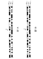
- FIG. 1A is a diagram schematically showing a dot pattern in the (n ⁇ 1) th to (n + 1) th nozzles based on the initial printing rate when the ejection of the gel ink from the nth nozzle is stopped
- FIG. FIG. 6 is a diagram schematically showing dot patterns after correction in the (n ⁇ 1) th and (n + 1) th nozzles.
- the ink jet image forming method is a so-called line head type ink jet image forming method. That is, in the image forming method, the gel ink is transferred from the plurality of nozzles arranged along the first direction to the recording medium moving in the second direction across the first direction at the first printing rate. The process (printing process) of discharging is included.
- the first printing rate is a printing rate for uniting the newly ejected gel ink dots with the gel ink dots that have already landed on the recording medium.
- “Making dots together” means, for example, that the dots of gel ink that are newly landed on the recording medium come into contact with or overlap with the existing dots on the recording medium, or the above-mentioned wet spreading of the new dots. , Says to be integrated with the existing dots.
- the “printing rate” is the ratio (%) of pixels on which an ink droplet of gel ink from the nozzle lands with respect to all the pixels in the row of pixels corresponding to one nozzle of the image to be formed.
- the first printing rate is an appropriate numerical value of less than 100%. For example, in consideration of the wetting and spreading, maximum printing for realizing a minimum dot diameter for a new dot to be integrated with an existing dot. It is an appropriate numerical value less than the rate.
- the first printing rate can be appropriately determined according to the dot diameter of the gel ink ejected from each nozzle, for example. Setting a larger dot diameter makes it possible to reduce the first printing rate and is preferable from the viewpoint of image productivity. Setting a smaller dot diameter requires increasing the first printing rate, which is preferable from the viewpoint of improving image quality.
- the dot diameter is, for example, the size of a point formed after wetting and spreading of an ink droplet that has landed on a recording medium.
- the first printing rate is set to 0.3 to 0.7 times the maximum printing rate from the viewpoint of image productivity, for example. More specifically, the first printing rate is preferably 35 to 65%, and more preferably 40 to 60%.
- the recording medium is an object to which gel ink can be applied by a line head type inkjet image forming method.
- the form of the recording medium is normally a sheet, but may be other forms as long as the gel ink can be applied in the present embodiment.
- Examples of the recording medium include various types of coated paper for printing, vapor-deposited paper, aluminum foil paper, polyethylene terephthalate (PET) sheet, polypropylene (PP) sheet, fine paper, cardboard, art paper, cardboard paper, and coated ball Includes paper, embossed paper and cloth.
- the recording medium is selected from objects having a contact angle of 15 to 30 ° with the gel ink.
- the contact angle can be determined using, for example, a commercially available contact angle meter. If the contact angle is too small, gel ink bleeding increases, which may lead to poor image granularity. If the contact angle is too large, the gel ink dots may rise from the surface of the recording medium, resulting in poor curing of the gel ink, and the adhesion of the dots to the recording medium may be insufficient. From the viewpoint of improving the image quality, the contact angle is preferably 18 to 28 °, and more preferably 20 to 26 °.
- the gel ink preferably has a phase transition temperature.
- the phase transition temperature of gel ink is the temperature at which the gel ink changes from a liquid to a solid. If the phase transition temperature is too low, ink ejection stability may not be obtained in a high-temperature environment such as summertime, or pinning stability may not be obtained, which may affect sensitivity, and the phase transition temperature is too high.
- the phase transition temperature of the gel ink is preferably 40 ° C. or higher and lower than 100 ° C., and more preferably 45 to 75 ° C.
- the phase transition temperature can be determined from viscoelastic curves obtained using various rheometers (for example, a stress control type rheometer using a cone plate, Physica MCR series, manufactured by Anton Paar).
- the viscoelastic curve can be obtained, for example, by measuring a viscosity curve obtained by changing a temperature of a high-temperature ink in a sol state at a low shear rate, or a temperature change of dynamic viscoelasticity.
- the gelation temperature can be appropriately adjusted by changing the type of gelling agent used, the amount of gelling agent added, and the type of actinic ray curable monomer.
- the gel ink contains a crystalline gelling agent, a coloring material, and a polymer dispersant.
- the crystalline gelling agent is a component that imparts fluidity to the gel ink before ejection and promotes solidification of the gel ink after landing, and may be one kind or more. If the content of the crystalline gelling agent in the gel ink is too small, the pinning of the gel ink is weak, so that an undesirable liquid shift due to dot coalescence may occur, and if too large, the pinning of the gel ink is too strong. In some cases, a sufficiently large dot cannot be obtained. From such a viewpoint, the content is preferably 1 to 20% by mass, more preferably 1 to 10% by mass, and further preferably 2 to 7% by mass.
- crystalline gelling agent examples include fatty acid inulin such as inulin stearate, fatty acid dextrin such as dextrin palmitate and dextrin myristic acid, glyceryl behenate, and polyglyceryl behenate eicosane diacid. .
- crystalline gelling agent examples include low molecular oil gelling agents described in JP-A-2005-126507, JP-A-2005-255821, JP-A-2010-1111790, N-lauroyl- Amide compounds such as L-glutamic acid dibutylamide and N-2 ethylhexanoyl-L-glutamic acid dibutylamide, and dibenzylidene sorbitols such as 1,3: 2,4-bis-O-benzylidene-D-glucitol included.
- N-lauroyl- Amide compounds such as L-glutamic acid dibutylamide and N-2 ethylhexanoyl-L-glutamic acid dibutylamide
- dibenzylidene sorbitols such as 1,3: 2,4-bis-O-benzylidene-D-glucitol included.
- crystalline gelling agent examples include petroleum waxes such as paraffin wax, microcrystalline wax, petrolactam, candelilla wax, carnauba wax, rice wax, wood wax, jojoba oil, jojoba solid wax, jojoba.
- Plant waxes such as esters, animal waxes such as beeswax and lanolin, whale wax, mineral waxes such as montan wax and hydrogenated wax, hardened castor oil or hardened castor oil derivatives and montan wax derivatives, and paraffin wax derivatives
- Modified waxes such as microcrystalline wax derivatives and polyethylene wax derivatives are included.
- crystalline gelling agent examples include higher fatty acids such as behenic acid, arachidic acid, stearic acid, palmitic acid, myristic acid, lauric acid, oleic acid, erucic acid, stearyl alcohol and behenyl alcohol.
- Higher alcohols such as 12-hydroxystearic acid or derivatives thereof, lauric acid amide or stearic acid amide, behenic acid amide, oleic acid amide, erucic acid amide, ricinoleic acid amide, 12-hydroxy Fatty acid amides such as stearic acid amide, and N-substituted fatty acid amides such as N-stearyl stearic acid amide and N-oleyl palmitic acid amide are included.
- the crystalline gelling agent examples include special fatty acids such as N, N′-ethylenebisstearylamide, N, N′-ethylenebis12-hydroxystearylamide, and N, N′-xylylenebisstearylamide.
- Amides, higher amines such as dodecylamine, tetradecylamine, octadecylamine, stearyl stearic acid, oleyl palmitic acid, glycerin fatty acid ester, sorbitan fatty acid ester, propylene glycol fatty acid ester, ethylene glycol fatty acid ester, polyoxyethylene fatty acid
- Fatty acid ester compounds such as esters, sucrose fatty acid esters such as sucrose stearic acid and sucrose palmitic acid, synthetic gelling agents such as polyethylene gelators and ⁇ -olefin maleic anhydride copolymer gelling agents, polymerizable gels Agent, da Mer acid and dimer diol, it contains.
- the color material may be one kind or more. If the content of the color material in the gel ink is too small, the color of the gel ink may be insufficient, and if it is too large, other properties of the gel ink may be insufficient. From such a viewpoint, the content of the color material in the gel ink is preferably 0.5 to 10% by mass, more preferably 0.5 to 7% by mass, and 1 to 5% by mass. More preferably it is.
- Examples of the color material include pigments and dyes that are known to be usable as color materials for inkjet inks.
- examples of the pigment include organic pigments and inorganic pigments described in the color index.
- examples of the dye include oil-soluble dyes.
- the type of the polymer dispersant is not particularly limited.
- Preferred examples of the polymer dispersant include BYK-2164, BYK-168, BYK N-22024, manufactured by BYK Chemie, BYK JET-9150, BYK JET-9151, BYK JET-9151, EFKA 7701, EFKA 4310, manufactured by BASF. , EFKA 4320, EFKA 4401, Avecia's SOLPERSE 24000GR, SOLPERSE 39000, Ajinomoto Fine Techno Co., Ltd. Ajisper (registered trademark of Ajinomoto Co., Inc.) PB821, PB824, and the like.
- the polymer dispersant preferably has a comb block structure (block copolymer (comb shape) skeleton) from the viewpoint of enhancing the dispersibility of the pigment (coloring material).
- a comb block structure block copolymer (comb shape) skeleton
- the content of the polymer dispersant is preferably 20 to 70% by mass, more preferably 25 to 60% by mass, and further preferably 30 to 50% by mass with respect to the pigment. If the content of the polymer dispersant relative to the pigment is too high, the polymer dispersant associates with the gelling agent to inhibit gelation, and pinning does not work when the ink droplets land, causing the droplets to spread and liquid. This is because droplets overlap, so-called liquid deviation occurs, resulting in insufficient image quality. On the other hand, if the content of the polymer dispersant relative to the pigment is low, the polymer surface cannot be sufficiently covered with the polymer dispersant, so that the storage stability is lowered and the ejection stability is also deteriorated. Elasticity may not be obtained.
- the gel ink may further contain components other than the above-described crystalline gelling agent, colorant, and polymer dispersant as long as the effects of the present embodiment are exhibited.
- the other components include a photopolymerizable compound and a photopolymerization initiator.
- the above-mentioned photopolymerizable compound is a compound that is cured by irradiation with light described later, and may be one kind or more. If the content of the photopolymerizable compound in the gel ink is too small, the coloring material cannot be sufficiently dispersed, and the ink dischargeability from the ink jet recording apparatus is reduced, or the formed image (ink layer) ) May be insufficient, and if it is too large, the amount of gelling agent and photopolymerization initiator will be relatively small, the sol-gel phase transition will not be sufficiently performed, and curing will be insufficient. Other properties in the gel ink may be insufficient.
- the content of the photopolymerizable compound in the gel ink is preferably 10 to 97% by mass, and 20 to 90% by mass. % Is more preferable, and 30 to 85% by mass is even more preferable.
- Examples of the photopolymerizable compound include compounds having one or more radical polymerizable unsaturated multiple bonds, and more specifically, compounds having one or more (meth) acryloyl groups.
- Examples of compounds having one (meth) acryloyl group include isoamyl (meth) acrylate, stearyl (meth) acrylate, lauryl (meth) acrylate, octyl (meth) acrylate, decyl (meth) acrylate, and isomyristyl (meth) acrylate , Isostearyl (meth) acrylate, 2-ethylhexyl-diglycol (meth) acrylate, 2-hydroxybutyl (meth) acrylate, 2-acryloyloxyethyl hexahydrophthalic acid, butoxyethyl (meth) acrylate, ethoxydiethylene glycol (meta ) Acrylate, methoxydiethylene glycol (meth) acrylate, methoxypolyethylene glycol (meth) acrylate, methoxypropylene glycol (meth) acrylate, pheno Siethyl (meth)
- Examples of compounds having two (meth) acryloyl groups include triethylene glycol di (meth) acrylate, tetraethylene glycol di (meth) acrylate, polyethylene glycol di (meth) acrylate, tripropylene glycol di (meth) acrylate, Polypropylene glycol di (meth) acrylate, 1,4-butanediol di (meth) acrylate, 1,6-hexanediol di (meth) acrylate, 1,9-nonanediol di (meth) acrylate, neopentyl glycol di (meth) ) Acrylate, dimethylol-tricyclodecane di (meth) acrylate, bisphenol A PO adduct di (meth) acrylate, hydroxypivalate neopentyl glycol di (meth) acrylate, and polytetramethyl It includes glycol di (meth) acrylate.
- Examples of compounds having three or more (meth) acryloyl groups include trimethylolpropane tri (meth) acrylate, pentaerythritol tri (meth) acrylate, pentaerythritol tetra (meth) acrylate, dipentaerythritol hexa (meth) acrylate , Ditrimethylolpropane tetra (meth) acrylate, glycerin propoxytri (meth) acrylate, caprolactone modified trimethylolpropane tri (meth) acrylate, pentaerythritol ethoxytetra (meth) acrylate and caprolactam modified dipentaerythritol hexa (meth) acrylate It is.
- the actinic ray curable compound preferably contains a compound having two or more (meth) acryloyl groups from the viewpoint of increasing the strength of the ink layer.
- the content of the compound having two or more (meth) acryloyl groups in the actinic ray curable compound is 30 to 100% by mass.
- the photopolymerization initiator is a component that causes a polymerization reaction of the photopolymerizable compound by the light, and may be one kind or more. If the content of the photopolymerization initiator in the gel ink is too small, the photocuring of the gel ink may be insufficient, and if it is too large, the effect of the photopolymerization initiator reaches its peak. From such a viewpoint, the content of the photopolymerization initiator in the gel ink is preferably 0.01 to 10% by mass, more preferably 1 to 9% by mass, and 5 to 8% by mass. More preferably it is.
- photopolymerization initiator examples include acetophenone series, benzoins, acylphosphine oxide series, benzyl, and methylphenylglyoxyester.
- acetophenone series examples include diethoxyacetophenone, 2-hydroxy-2-methyl-1-phenylpropan-1-one, benzyldimethyl ketal, 1- (4-isopropylphenyl) -2-hydroxy-2-methylpropane -1-one, 4- (2-hydroxyethoxy) phenyl- (2-hydroxy-2-propyl) ketone, 1-hydroxycyclohexyl-phenylketone, 2-methyl-2-morpholino (4-thiomethylphenyl) propane- 1-one and 2-benzyl-2-dimethylamino-1- (4-morpholinophenyl) -butanone are included.
- benzoins examples include benzoin, benzoin methyl ether and benzoin isopropyl ether.
- acylphosphine oxide examples include 2,4,6-trimethylbenzoindiphenylphosphine oxide.
- intramolecular hydrogen abstraction type photopolymerization initiator examples include benzophenone series, thioxanthone series, aminobenzophenone series, 10-butyl-2-chloroacridone, 2-ethylanthraquinone, and 9,10-phenanthrenequinone. And camphorquinone.
- benzophenone series examples include benzophenone, methyl-4-phenylbenzophenone o-benzoylbenzoate, 4,4′-dichlorobenzophenone, hydroxybenzophenone, 4-benzoyl-4′-methyl-diphenyl sulfide, acrylated benzophenone, 3 3,3 ′, 4,4′-tetra (t-butylperoxycarbonyl) benzophenone and 3,3′-dimethyl-4-methoxybenzophenone.
- Examples of the above thioxanthone series include 2-isopropylthioxanthone, 2,4-dimethylthioxanthone, 2,4-diethylthioxanthone, and 2,4-dichlorothioxanthone.
- aminobenzophenone series examples include Michler's ketone and 4,4'-diethylaminobenzophenone.
- R is the resolution (dpi) of the image to be formed
- D is the dot diameter ( ⁇ m) of the ink droplet landed on the recording medium. 2.7 ⁇ D / (2.54 ⁇ 10 4 /R) ⁇ 3.5
- the pixel dot ratio is preferably 2.9 to 3.3.
- the pixel dot ratio can be obtained by calculation, for example, from the desired resolution of the image, the type of recording medium to be used, the contact angle of the gel ink, etc., or can be obtained by an experiment with an actual machine. .
- the inkjet image forming method may further include other steps than the printing step as long as the effects of the present embodiment are achieved.
- the other processes include an abnormal nozzle identification process, a discharge stop process, a printing rate adjustment process, and a photocuring process.
- an abnormal nozzle that has caused an abnormal discharge from a plurality of nozzles is specified.
- the ejection stop step the ejection of the gel ink from the abnormal nozzle is stopped.
- the printing rate of the nozzle adjacent to one or both of the abnormal nozzles is adjusted to a second printing rate larger than the first printing rate. Thereafter, the adjacent nozzles eject the gel ink onto the recording medium at the second printing rate.
- the adjacent nozzle adjusted to the second printing rate may be only one adjacent nozzle of the abnormal nozzle, or may be both adjacent nozzles. From the viewpoint of suppressing deterioration in image quality, it is preferable that the printing rate of the nozzles on both sides is adjusted to the second printing rate.
- the second printing rate is a minimum printing rate or more than that for filling the blank portion formed on the recording medium when the dots of the gel ink from the adjacent nozzles are stopped by the ejection of the gel ink from the abnormal nozzles. Value.
- the upper limit is 100%.
- the second printing rate may be the same for the upper adjacent nozzles or may be different.
- the second print rate is preferably 1.1 to 2.0 times the first print rate, and 1.3 to 1.
- the number is more preferably 8 times, and further preferably 1.4 to 1.7 times.
- the printing rate adjustment step can be performed, for example, using the correction mechanism designed so that the printing rate of a specific nozzle can be adjusted.
- the gel ink on the recording medium is cured by irradiating light onto the ink droplet landed on the recording medium of the gel ink containing the photopolymerizable compound and the photopolymerization initiator.
- the light is light that causes photopolymerization of the photopolymerizable compound, and is, for example, ultraviolet light or an electron beam.
- the photocuring step can be performed using the light source disposed on the downstream side of the line ink jet head in the recording medium transport direction in the line head type ink jet image forming apparatus. Similar to the line inkjet head, the light source may be fixed so as to irradiate the light to the full width of the image to be formed, or arranged so as to be able to scan in the direction crossing the transport direction. May be.
- the ink jet image forming method can be performed using a known line head type ink jet image forming apparatus having a mechanism capable of changing the printing rate of the nozzles adjacent to the missing nozzle as a missing nozzle correcting mechanism.
- a line head type inkjet image forming apparatus having missing nozzle correction means is prepared.
- the line head type inkjet image forming apparatus for example, an inkjet recording apparatus described in JP-A-2004-306261 can be used.
- the missing nozzle correction means may be, for example, a discharge amount switching means described in Patent Document 1 that is designed to adjust the printing rate of the nozzles instead of adjusting the ink discharge amount.
- ink is ejected from each nozzle under an initial condition that satisfies the pixel dot ratio to form an image.
- the printing rate of each nozzle is normally 100%.
- the printing rate of each nozzle is less than 100%. If the dot diameter is too large, the pixels become coarse and the desired image quality cannot be realized.
- the initial condition can be set by, for example, an experiment using an actual machine and a sensory evaluation of an image based on the above-described balance.
- FIG. 1A shows the dot patterns DP (n ⁇ 1) , DP (n) and DP (n + 1) of the nth nozzle and the adjacent nozzles at this time.
- the squares in the figure represent pixels on the recording medium, and the filled portions represent pixels on which ink on the recording medium is to be ejected.
- An arrow X represents the conveyance direction of the recording medium.
- the dot pattern DP (n ⁇ 1) of the (n ⁇ 1) th nozzle and the dot pattern DP (n + 1) of the (n + 1) th nozzle are dot patterns based on the above initial conditions.
- the missing nozzle correction means increases the printing rate of the (n ⁇ 1) th and (n + 1) th nozzles in the initial condition.
- the shaded area in FIG. 1B indicates a pixel for which ink ejection has been newly set to increase the printing rate.
- a dot in both nozzles fills a blank of the pixel row corresponding to the nth nozzle.
- the pixels to be newly ejected from the (n ⁇ 1) th and (n + 1) th nozzles are set as the pixels that should be printed by ejecting ink from the nth nozzle. This can be done by setting the ink droplets to land on adjacent pixel positions or adjacent pixel positions.
- the ink droplets to be ejected are applied to the pixel corresponding to the nth nozzle or the adjacent pixel or the adjacent pixel. Let it be distributed. In this way, by increasing the printing ratio of the (n ⁇ 1) th and (n + 1) th nozzles, the occurrence of streak defects due to the stop of the discharge of the nth nozzle is prevented, and an image with the desired image quality continues to be formed.
- the new dot is added to the dot pattern in the initial state of the (n ⁇ 1) th and (n + 1) th nozzles to increase the printing rate of both nozzles.
- the (n + 1) th dot pattern may be accompanied by a partial change of the initial dot pattern portion, or may be a newly set dot pattern other than the initial dot pattern. Further, by changing the dot pattern in the region including the (n ⁇ m) th and n + mth (n ⁇ 5, m ⁇ 4), further non-uniformity and further improvement in image quality can be expected.
- the inkjet image forming method is a recording medium that moves in a second direction across the first direction from a plurality of nozzles arranged along the first direction.
- a first printing rate of less than 100% for uniting the newly ejected gel ink dots with the gel ink dots already landed on the recording medium.
- the gel ink contains a crystalline gelling agent, a colorant and a polymer dispersant, and the content of the polymer dispersant in the gel ink is greater than 20% by mass and less than or equal to 70% by mass with respect to the colorant.
- the contact angle Ga of the gel ink of the recording medium is 15 to 30 ° and satisfies the following formula, the occurrence of image defects due to defective ejection of ink from the nozzles is further suppressed. It can be suppressed to. 2.7 ⁇ D / (2.54 ⁇ 10 4 /R) ⁇ 3.5
- R is the resolution (dpi) of the image to be formed
- D is the dot diameter ( ⁇ m) of the ink droplet landed on the recording medium.
- the inkjet image forming method includes a step of identifying an abnormal nozzle that has caused an abnormal discharge from the plurality of nozzles, a step of stopping the discharge of the gel ink from the abnormal nozzle, and one or both of the abnormal nozzles Adjusting the printing rate of the nozzle adjacent to the second printing rate to be larger than the first printing rate and discharging the gel ink onto the recording medium. This is more effective from the viewpoint of more easily suppressing the occurrence of image defects due to the ejection failure.
- the gel ink has a phase transition point at 40 ° C. or higher and lower than 100 ° C. from the viewpoint of improving ejection stability and ink droplet landing accuracy.
- the content of the crystalline gelling agent in the gel ink is 1 to 10% by mass, which is more effective from the viewpoint of realizing the desired image quality related to dot spreading.
- the polymer dispersant is at least one selected from the group consisting of polymer dispersants having a comb block structure from the viewpoint of enhancing dispersion stability and ejection stability.
- the gel ink further contains a photopolymerizable compound and a photopolymerization initiator, and the ink jet image forming method cures the gel ink on the recording medium by irradiating the ink droplets landed on the recording medium with light. Further including is more effective from the viewpoint of forming a highly durable image.
- magenta pigment dispersion 1 was prepared with the following components.
- Magenta pigment 1 D4500J (manufactured by BASF) 9.0 g
- Photopolymer compound Tripropylene glycol diacrylate (manufactured by Toa Gosei Co., Ltd.) 32.7 g
- Polymer dispersing agent BYK Jet-9151 (manufactured by Altana) 3.2 g
- Pigment dispersions 2 and 3 were obtained in the same manner as pigment dispersion 1, except that the D / P was changed to 0.20 and 0.80, respectively.
- Photopolymerization compound polyethylene glycol diacrylate (PEGDA) (manufactured by Daicel Ornex Co., Ltd.) 6.2 g Photopolymerization compound: 3PO-modified trimethylolpropane triacrylate (manufactured by Toa Gosei Co., Ltd.) 6.2 g Surfactant: TSF-4442 (manufactured by Shin-Etsu Chemical Co., Ltd.) 0.3 g Photopolymerization initiator: IRGACURE 819 (manufactured by BASF) 0.3 g Photopolymerization initiator: DAROCURE TPO (BASF) 0.3g Crystalline gelling agent: Kao wax T-1 (manufactured by Kao Corporation) 0.8 g
- Inks 2 and 3 were obtained in the same manner as ink 1 except that pigment dispersions 2 and 3 were used instead of pigment dispersion 1, respectively. Further, an ink 4 was obtained in the same manner as the ink 1 except that the crystalline gelling agent 1 was replaced with the same amount of the photopolymerizable compound 1.
- the ratio D / P of the content D of the polymer dispersant 1 to the content P of the magenta pigment in the ink 1 is 0.35.
- D / P of ink 2 is 0.20
- D / P of ink 3 is 0.80
- D / P of ink 4 is 0.35.
- phase transition temperature (gelation temperature) Tpt of the inks 1 to 3 was measured with a viscoelasticity measuring device MCR300 manufactured by Physica, share rate 11 (1 / s). Inks 1 to 3 all had a Tpt of 59 ° C. Since ink 4 did not gel, Tpt was not determined.
- Example 1 Using a line head type inkjet image forming apparatus in which the temperature of the inkjet head was set to 80 ° C., the ink 1 was ejected onto the recording medium A to form a solid image 1 of 5 cm ⁇ 5 cm.
- the liquid volume of the ink 1 droplet is 9 pL
- the resolution R of the image to be formed in the nozzle arrangement direction of the inkjet head is 1200 dpi
- the dot diameter D of the ink 1 landed on the recording medium A is 65 ⁇ m. .
- the printing rate Cr (n) at the nth nozzle (for example, the 100th nozzle from one end nozzle) in the inkjet head is 50%, and the printing rate Cr (n ⁇ 1) at the (n ⁇ 1) th nozzle is 45%.
- the printing rate Cr (n + 1) at the (n + 1) th nozzle is 53%.
- the printing rate is the ratio (%) of pixels that actually land ink in a row of pixels that can be printed by each nozzle.
- the streaks, curability, graininess, and adhesion of the obtained solid image 1 were evaluated.
- Streak Defect Image data was thinned out at a predetermined interval in advance, and a solid image 1 forcibly including nozzle defects was visually observed, and streak-like image defects were evaluated according to the following criteria. If it is “A” or “B”, there is no practical problem. A: No streak is visible at any point. B: White background is not visible, but part of the image has streak-like irregularities. C: Some streak-like white spots can be recognized. D: In most places. Line-shaped white spots can be recognized
- the adhesion of the ink 1 layer to the recording medium A was evaluated according to the following criteria. If it is “A” or “B”, there is no practical problem.
- D The number of peeled cut parts is More than 40
- Example 2 to 5 Solid images 2 and 3 were formed and evaluated in the same manner as in Example 1 except that the amount of ink droplets was changed to 8.5 pL and 9.5 pL, respectively.
- a solid image 3 was formed and evaluated in the same manner as in Example 1 except that the recording medium A was replaced with the recording medium B.
- “Recording medium B” was a single-sided chrome color (manufactured by Oji Paper Co., Ltd.), and the contact angle after 1 second of landing of ink 1 on recording medium B was 25 °.
- a solid image 4 was formed and evaluated in the same manner as in Example 1 except that the recording medium A was replaced with the recording medium C.
- “Recording medium C” was Esprit C (manufactured by Nippon Paper Industries Co., Ltd.), and the contact angle after 1 second of landing of ink 1 on recording medium C was 28 °.
- Solid images C1 to C3 were formed and evaluated in the same manner as in Example 1 except that the recording medium A was replaced with recording media D, E, and F, respectively.
- “Recording medium D” is a PET film with easy contact treatment
- “Recording medium E” is Esprit F (manufactured by Nippon Paper Industries Co., Ltd.)
- “Recording medium F” is high gloss paper (M-real). Made).
- the contact angle after 1 second of the landing of the ink 1 with respect to the recording medium D is 10 °
- the contact angle after the landing of the ink 1 with respect to the recording medium E is 32 °
- the landing of the ink 1 with respect to the recording medium F The contact angle after 1 second was 47 °.
- Solid images C4 to C6 were formed and evaluated in the same manner as in Example 1 except that ink 1 was replaced with inks 2 to 4, respectively.
- the contact angle after 1 second of landing of the ink 2 on the recording medium A is 23 °
- the contact angle after 1 second of landing of the ink 3 on the recording medium A is 20 °
- the landing angle of the ink 4 on the recording medium A is 1 second.
- the later contact angle was 13 °.
- Example 7 A solid image C7 was formed and evaluated in the same manner as in Example 1 except that the liquid volume of the ink 1 droplet was changed to 8 pL and the dot diameter was changed to 55 ⁇ m.
- Example 8 A solid image C8 was formed and evaluated in the same manner as in Example 1 except that the liquid volume of the ink 1 droplet was changed to 10 pL and the dot diameter was changed to 78 ⁇ m.
- Example 6 A solid image 6 is formed in the same manner as in Example 1 except that the liquid volume of the ink 1 droplet is changed to 14 pL, the dot diameter is changed to 124 ⁇ m, and the resolution of the image to be formed is changed to 600 dpi. evaluated.
- Table 1 shows conditions and evaluation results of the ink jet image forming methods in Examples and Comparative Examples.
- Example 7 Implemented except that the ejection of ink 1 from the nth nozzle was stopped, the printing rate of the (n-1) th nozzle was changed from 45% to 75%, and the printing rate of the (n + 1) th nozzle was changed from 53% to 72%. In the same manner as in Example 1, a solid image 7 was produced, and stripe defects in the solid image 7 were evaluated.
- Example 9 A solid image C9 was produced in the same manner as in Example 1 except that the ejection of the ink 1 from the n-th nozzle was stopped, and streak defects in the solid image C9 were evaluated.
- a solid image C10 was produced in the same manner as in Example 7 except that the recording medium A was replaced with the recording medium F, and streak defects in the solid image C10 were evaluated.
- Example 8 A solid image was obtained in the same manner as in Example 1 except that the printing rate of the (n-1) th nozzle was 34%, the printing rate of the nth nozzle was 50%, and the printing rate of the (n + 1) th nozzle was 62%. 8A was produced. Thus, it was confirmed that a solid image could be produced at the above printing rate.
- a solid image C12 was produced in the same manner as the solid image 8A in Example 8 except that the ejection of the ink 1 from the n-th nozzle was stopped, and streak defects in the solid image C12 were evaluated.
- Table 2 shows the evaluation results of the printing rate and streak defects in Examples 7 and 8 and Comparative Examples 9 to 12.
- Examples 1 to 6 show sufficiently good results in any evaluation of streak defects, curability, graininess, and adhesion. This is because (1) in the line head type ink jet image forming method, the gel ink is ejected at an appropriate printing rate for merging new dots with the existing dots and at a dot diameter suitable for the resolution. (2) In the gel ink, the polymer dispersant is sufficiently contained in the coloring material, and (3) the gel ink has an appropriate contact angle with respect to the recording medium, This is considered to be due to the three points.
- Examples 7 and 8 were evaluated in any evaluation of streak defects, curability, granularity, and adhesion, both before and after stopping the discharge of ink from the nth nozzle. It shows sufficiently good results. This is because, in addition to the above (1), after the ink ejection from the n-th nozzle is stopped, the printing rate at both adjacent nozzles is appropriately increased.
- Comparative Example 1 the evaluation result of graininess is insufficient. This is presumably because the contact angle of the ink 1 with respect to the recording medium D is too small, the bleeding becomes large, and the dot diameter is too large for the pixels.
- Comparative Example 2 the evaluation results of streak defects and graininess are insufficient, and in Comparative Example 3, the evaluation results of any of streak defects, curability, graininess, and adhesion are insufficient. This is considered to be because, in Comparative Examples 2 and 3, the contact angle of the ink 1 with respect to each of the recording media E and F is too large, the dots rise, and the dot diameter is too small with respect to the pixels. In Comparative Example 3, it is considered that the rise of dots resulted in insufficient graininess and poor curing of the ink 3 and a decrease in the adhesion of the ink 3 to the recording medium F.
- Comparative Example 6 the evaluation results for all of curability, graininess, and adhesion are insufficient. This is because the ink 4 is a non-gel ink that does not contain a crystalline gelling agent, so that no streak defects occur, but the gel ink-specific effects (improving curability, graininess, and adhesion) cannot be obtained. Conceivable.
- the first printing of less than 100% for uniting the newly ejected gel ink dots toward the gel ink dots that have already landed on the recording medium In forming the image by discharging the gel ink at a rate, the gel ink contains a crystalline gelling agent, a colorant and a polymer dispersant, and the content of the polymer dispersant in the gel ink is in the colorant.
- the contact angle of the gel ink of the recording medium is 15 to 30 ° and satisfies the following formula, the above-described streak defect and grain defect are satisfied. It can be seen that an image having sufficient ink curability and adhesion can be formed.
- the present invention in the line head type ink jet image forming method in which an image is formed by one pass of a recording medium, an image can be formed with higher productivity, and streaks due to nozzle defects can be formed. It is possible to prevent the occurrence of defects by an easier method of adjusting the nozzle printing rate. Therefore, the present invention is expected to contribute to the further popularization of the line head type inkjet image forming method using gel ink in the printing industry where high quality images are required to be formed with high productivity.
Landscapes
- Chemical & Material Sciences (AREA)
- Engineering & Computer Science (AREA)
- Materials Engineering (AREA)
- Wood Science & Technology (AREA)
- Organic Chemistry (AREA)
- Life Sciences & Earth Sciences (AREA)
- Quality & Reliability (AREA)
- Physics & Mathematics (AREA)
- Electromagnetism (AREA)
- General Health & Medical Sciences (AREA)
- Toxicology (AREA)
- Health & Medical Sciences (AREA)
- Ink Jet Recording Methods And Recording Media Thereof (AREA)
- Inks, Pencil-Leads, Or Crayons (AREA)
- Ink Jet (AREA)
Abstract
Priority Applications (2)
| Application Number | Priority Date | Filing Date | Title |
|---|---|---|---|
| JP2016573304A JP6677175B2 (ja) | 2015-02-05 | 2016-01-27 | ラインヘッド式インクジェット画像形成方法 |
| US15/548,584 US9975328B2 (en) | 2015-02-05 | 2016-01-27 | Inkjet image-forming method |
Applications Claiming Priority (2)
| Application Number | Priority Date | Filing Date | Title |
|---|---|---|---|
| JP2015021292 | 2015-02-05 | ||
| JP2015-021292 | 2015-09-29 |
Publications (1)
| Publication Number | Publication Date |
|---|---|
| WO2016125656A1 true WO2016125656A1 (fr) | 2016-08-11 |
Family
ID=56564005
Family Applications (1)
| Application Number | Title | Priority Date | Filing Date |
|---|---|---|---|
| PCT/JP2016/052343 Ceased WO2016125656A1 (fr) | 2015-02-05 | 2016-01-27 | Procédé de formation d'image par jet d'encre |
Country Status (3)
| Country | Link |
|---|---|
| US (1) | US9975328B2 (fr) |
| JP (1) | JP6677175B2 (fr) |
| WO (1) | WO2016125656A1 (fr) |
Cited By (1)
| Publication number | Priority date | Publication date | Assignee | Title |
|---|---|---|---|---|
| JPWO2017014014A1 (ja) * | 2015-07-21 | 2018-05-24 | コニカミノルタ株式会社 | 色インクを用いたインクジェット記録方法 |
Citations (8)
| Publication number | Priority date | Publication date | Assignee | Title |
|---|---|---|---|---|
| JP2005074956A (ja) * | 2003-09-03 | 2005-03-24 | Fuji Photo Film Co Ltd | 画像形成装置及び画像形成方法 |
| WO2011136009A1 (fr) * | 2010-04-28 | 2011-11-03 | コニカミノルタホールディングス株式会社 | Procédé pour produire une matière imprimée |
| JP2012071568A (ja) * | 2009-10-08 | 2012-04-12 | Fujifilm Corp | インクジェット記録装置及び方法並びに異常ノズル検知方法 |
| WO2012114759A1 (fr) * | 2011-02-24 | 2012-08-30 | コニカミノルタホールディングス株式会社 | Encre pour jet d'encre durcissable sous rayonnement actinique et procédé de formation d'image |
| WO2013161298A1 (fr) * | 2012-04-27 | 2013-10-31 | コニカミノルタ株式会社 | Encre pour jet d'encre durcissable par rayonnement actif et procédé de formation d'image l'utilisant |
| JP2013226745A (ja) * | 2012-04-26 | 2013-11-07 | Konica Minolta Inc | 画像形成方法 |
| JP2013240978A (ja) * | 2012-04-25 | 2013-12-05 | Seiko Epson Corp | インクジェット記録方法、紫外線硬化型インク、インクジェット記録装置 |
| JP2014118570A (ja) * | 2012-12-18 | 2014-06-30 | Xerox Corp | オレンジ硬化性インク |
Family Cites Families (3)
| Publication number | Priority date | Publication date | Assignee | Title |
|---|---|---|---|---|
| JPH0924609A (ja) | 1995-07-12 | 1997-01-28 | Mita Ind Co Ltd | インクジェットヘッド駆動装置 |
| JP2015187235A (ja) * | 2014-03-27 | 2015-10-29 | セイコーエプソン株式会社 | インク組成物、インクセット、及び記録方法 |
| JP6436165B2 (ja) * | 2014-04-03 | 2018-12-12 | コニカミノルタ株式会社 | 画像形成方法 |
-
2016
- 2016-01-27 US US15/548,584 patent/US9975328B2/en active Active
- 2016-01-27 JP JP2016573304A patent/JP6677175B2/ja active Active
- 2016-01-27 WO PCT/JP2016/052343 patent/WO2016125656A1/fr not_active Ceased
Patent Citations (8)
| Publication number | Priority date | Publication date | Assignee | Title |
|---|---|---|---|---|
| JP2005074956A (ja) * | 2003-09-03 | 2005-03-24 | Fuji Photo Film Co Ltd | 画像形成装置及び画像形成方法 |
| JP2012071568A (ja) * | 2009-10-08 | 2012-04-12 | Fujifilm Corp | インクジェット記録装置及び方法並びに異常ノズル検知方法 |
| WO2011136009A1 (fr) * | 2010-04-28 | 2011-11-03 | コニカミノルタホールディングス株式会社 | Procédé pour produire une matière imprimée |
| WO2012114759A1 (fr) * | 2011-02-24 | 2012-08-30 | コニカミノルタホールディングス株式会社 | Encre pour jet d'encre durcissable sous rayonnement actinique et procédé de formation d'image |
| JP2013240978A (ja) * | 2012-04-25 | 2013-12-05 | Seiko Epson Corp | インクジェット記録方法、紫外線硬化型インク、インクジェット記録装置 |
| JP2013226745A (ja) * | 2012-04-26 | 2013-11-07 | Konica Minolta Inc | 画像形成方法 |
| WO2013161298A1 (fr) * | 2012-04-27 | 2013-10-31 | コニカミノルタ株式会社 | Encre pour jet d'encre durcissable par rayonnement actif et procédé de formation d'image l'utilisant |
| JP2014118570A (ja) * | 2012-12-18 | 2014-06-30 | Xerox Corp | オレンジ硬化性インク |
Cited By (1)
| Publication number | Priority date | Publication date | Assignee | Title |
|---|---|---|---|---|
| JPWO2017014014A1 (ja) * | 2015-07-21 | 2018-05-24 | コニカミノルタ株式会社 | 色インクを用いたインクジェット記録方法 |
Also Published As
| Publication number | Publication date |
|---|---|
| US20180001620A1 (en) | 2018-01-04 |
| JPWO2016125656A1 (ja) | 2017-11-24 |
| US9975328B2 (en) | 2018-05-22 |
| JP6677175B2 (ja) | 2020-04-08 |
Similar Documents
| Publication | Publication Date | Title |
|---|---|---|
| JP5659619B2 (ja) | インクジェット記録方法 | |
| JP5741870B2 (ja) | 活性線硬化型インクジェット用インクおよびそれを用いた画像記録方法 | |
| JP5573485B2 (ja) | インクジェット記録方法およびインクジェット記録装置 | |
| JP5991371B2 (ja) | インクジェットインクセット、及びこれを用いた画像形成方法 | |
| WO2012023368A1 (fr) | Encre durcissable par rayonnement actif et procédé d'enregistrement à jet d'encre durcissable par rayonnement actif | |
| JP6038831B2 (ja) | インクジェット記録方法 | |
| JP6763395B2 (ja) | インクセット及び画像形成方法 | |
| US20200190349A1 (en) | Image forming method | |
| JP6303656B2 (ja) | ゾルゲル相転移型インクジェットインクを用いたインクジェット記録方法 | |
| JP6436165B2 (ja) | 画像形成方法 | |
| JP5703954B2 (ja) | インクジェット記録方法 | |
| EP3269782A1 (fr) | Encre durcissable par rayonnement actif pour jet d'encre comprenant deux types de cires qui forment un cristal eutectique et procédé d'impression par jet d'encre | |
| JP2020110949A (ja) | 画像形成方法 | |
| JP6677175B2 (ja) | ラインヘッド式インクジェット画像形成方法 | |
| JPWO2017126439A1 (ja) | 活性光線硬化型インクジェットインクおよびインクジェット記録方法 | |
| TW202317279A (zh) | 圖型形成方法及噴墨印刷裝置 | |
| CN105392633B (zh) | 喷墨打印方法 | |
| JPWO2016088873A1 (ja) | 画像形成方法 | |
| JP6948769B2 (ja) | 活性エネルギー線硬化型インクジェットインク組成物、及び、インクジェット記録方法 | |
| JP7831535B1 (ja) | 画像形成方法、画像形成装置、画像及びインクジェットインク | |
| US20250084222A1 (en) | Curable composition and method for producing cured film | |
| JP7405029B2 (ja) | 画像形成方法 | |
| JP2026036497A (ja) | インク、インクジェット記録方法及びインクジェット記録システム | |
| WO2015137506A1 (fr) | Encre pour impression jet d'encre de type durcissement actif à la lumière, procédé de remplissage et procédé de formation d'image | |
| JP2014148684A (ja) | 活性光線硬化型インク及びインクジェット記録方法 |
Legal Events
| Date | Code | Title | Description |
|---|---|---|---|
| 121 | Ep: the epo has been informed by wipo that ep was designated in this application |
Ref document number: 16746487 Country of ref document: EP Kind code of ref document: A1 |
|
| ENP | Entry into the national phase |
Ref document number: 2016573304 Country of ref document: JP Kind code of ref document: A |
|
| WWE | Wipo information: entry into national phase |
Ref document number: 15548584 Country of ref document: US |
|
| NENP | Non-entry into the national phase |
Ref country code: DE |
|
| 122 | Ep: pct application non-entry in european phase |
Ref document number: 16746487 Country of ref document: EP Kind code of ref document: A1 |