WO2016127385A1 - Appareil de carabine à air comprimé pouvant ajuster un recul amorti - Google Patents
Appareil de carabine à air comprimé pouvant ajuster un recul amorti Download PDFInfo
- Publication number
- WO2016127385A1 WO2016127385A1 PCT/CN2015/072978 CN2015072978W WO2016127385A1 WO 2016127385 A1 WO2016127385 A1 WO 2016127385A1 CN 2015072978 W CN2015072978 W CN 2015072978W WO 2016127385 A1 WO2016127385 A1 WO 2016127385A1
- Authority
- WO
- WIPO (PCT)
- Prior art keywords
- locking
- gun body
- lock
- gun
- recoil
- Prior art date
- Legal status (The legal status is an assumption and is not a legal conclusion. Google has not performed a legal analysis and makes no representation as to the accuracy of the status listed.)
- Ceased
Links
Images


Classifications
-
- F—MECHANICAL ENGINEERING; LIGHTING; HEATING; WEAPONS; BLASTING
- F41—WEAPONS
- F41B—WEAPONS FOR PROJECTING MISSILES WITHOUT USE OF EXPLOSIVE OR COMBUSTIBLE PROPELLANT CHARGE; WEAPONS NOT OTHERWISE PROVIDED FOR
- F41B11/00—Compressed-gas guns, e.g. air guns; Steam guns
-
- F—MECHANICAL ENGINEERING; LIGHTING; HEATING; WEAPONS; BLASTING
- F41—WEAPONS
- F41C—SMALLARMS, e.g. PISTOLS, RIFLES; ACCESSORIES THEREFOR
- F41C23/00—Butts; Butt plates; Stocks
Definitions
- the utility model relates to the field of firearms, in particular to an air gun device capable of adjusting a cushioning recoil.
- the air gun will generate a corresponding recoil force after launching the bullet, thereby affecting the accuracy of the shooting, changing the shooting position and angle of the air gun, and generating a large recoil force may cause physical discomfort or even damage to the user.
- the purpose of the utility model is to provide the above-mentioned problems and deficiencies, and to provide a method for ensuring the accuracy of the air gun and reducing the discomfort of the recoil, and the user can adjust the cushioning recoil force according to the needs of the use and adjust the air gun.
- the air gun device capable of adjusting the cushioning recoil force comprises a gun body and a launching device mounted on the gun body, wherein the rear end portion of the gun body is provided with a recoil cushioning device, and the recoil cushioning device comprises a device capable of moving back and forth a rear buttstock at the rear end of the gun body, a buffer spring disposed on the rear buttstock for cushioning the recoil, and a rear lockable butt and an adjustable rear butt lock position and an adjusted gun at the rear of the gun body
- a locking assembly extending rearwardly, the rear buttstock can buffer the airbag recoil force by the buffer spring when the air gun is fired, and can securely lock the rear buttstock to the gun through the locking assembly without buffering the backrest force Adjust the position of the rear butt lock as needed.
- the rear buttstock includes a rear support body at the rear end of the gun body, is connected to the rear support body and axially extends into the rear end of the gun body.
- a sleeve, a connecting shaft for connecting the rear buttstock to the gun body and the fixed gun body and the rear butt movement, the buffer spring is set on the connecting shaft or the sleeve, and the rear part of the gun body is correspondingly
- the slot is provided with a slot for the sleeve, and the locking assembly is slidably mounted to the side of the slot at the rear of the gun body and can be locked with the sleeve.
- the outer wall of the sleeve is provided with an axial rack, and the inner end of the locking assembly is correspondingly provided with the tooth
- the protruding teeth on the strip cooperate with the locking locking teeth.
- the specific structure of the above-mentioned locking component can be set according to different needs.
- the locking component in order to make the structure simple, can adopt a radial device at the rear end portion of the gun body, and the inner end thereof can cooperate with the sleeve column to lock the locking column.
- the utility model can further enhance the reliability of the locking structure while facilitating the adjustment of the position of the butt lock, and the locking assembly comprises a device that can be slid back and forth on the lower side of the rear cavity of the gun body.
- a fixing member for adjusting a locking position of the rear buttress
- a locking bolt laterally disposed on the fixing member
- a movable top member penetrating the locking bolt through a screw hole provided thereon
- the movable top piece is movably connected to the locking head, and the movable top piece moves to the middle of the locking bolt when the locking bolt rotates in one direction, and the top of the locking head locks the locking head and the sleeve, and the locking bolt is locked When you rotate in the opposite direction, go back and unlock.
- the utility model adopts a rear stocking device which is arranged at the rear end portion of the gun body and can be moved back and forth at the rear end portion of the gun body, a buffer spring which is arranged on the rear buttstock, and a lockable rear butt and adjustment at the rear of the gun body.
- the structure of the recoil cushioning device composed of the locking component of the rear butt lock position, etc., enables the user to use the elastic action of the buffer spring to buffer the recoil of the air gun during the shooting process, so as to reduce the recoil force and cause the body to the user.
- Discomfort or injury and improve shooting accuracy and can lock the rear butt completely to the gun without buffering the recoil, and can adjust the length of the rear of the gun according to the length of use of different users, so it is extremely It is convenient and effectively solves the problem that the existing air gun has a large recoil force and causes the user to be uncomfortable; or the structure is complicated and the use mode is single.
- the utility model has the advantages of simple structure, reliability, low production cost, multi-function use mode, and extremely convenient use, and can meet the requirements of the masses of consumers.
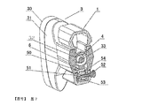
- Figure 1 is a schematic view showing the structure of the utility model in which the rear buttstock is completely locked to the gun body.
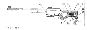
- FIG. 2 is a schematic cross-sectional structural view of FIG. 1.
- FIG. 2 is a schematic cross-sectional structural view of FIG. 1.
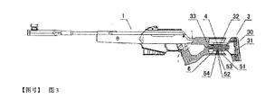
- FIG. 3 is a schematic cross-sectional structural view of FIG. 1 in which the lock of the buttstock is locked after the cushioning force is required to be buffered.
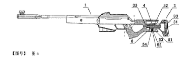
- FIG. 4 is a partial cross-sectional structural view of FIG. 1 fully locked after the length of the buttstock is adjusted.
- FIG. 5 is a schematic view of the assembled structure of FIG. 1.
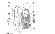
- Figure 6 is a cross-sectional view showing the structure of Figure B-B.
- Fig. 7 is a cross-sectional view showing the structure of Fig. 1 taken along the line B-B after the lock of the rear butt lock is released.
- the air gun device capable of adjusting the cushioning recoil force of the present invention comprises a gun body 1 and a launching device 2 mounted on the gun body 1.
- the gun body is as shown in FIG. 1 to FIG. 7 .
- the rear end portion is provided with a recoil cushioning device, and the recoil cushioning device comprises a rear buttstock 3 which is arranged to be moved back and forth to the rear end portion of the gun body 1, and the device is attached to the rear buttstock 3
- the buffer spring 4 can be used for buffering the recoil
- the rear of the gun body 1 is provided with a lockable assembly 5 for locking the rear butt 3 and the adjustable rear butt 3 locking position and the adjusted butt rearward extension length.
- the rear stock 3 can buffer the air gun recoil force by the buffer spring 4 when the air gun is fired, and can securely lock the rear stock 3 to the gun body 1 through the locking assembly 5 without the need for cushioning backrest force and according to Need to adjust the position of the rear butt 3 lock.
- the user can use the elastic action of the buffer spring 4 to buffer the recoil of the air gun, thereby reducing the discomfort or injury caused by the recoil force to the user and improving the shooting accuracy, and without the need for cushioning the sitting force.
- the rear stock 3 is completely locked to the gun body 1, and the length of the rear of the gun body (generally 25 mm in length range) can be adjusted according to the length requirements of different users.
- a soft rubber 30 having a shock absorbing effect may be provided at the rear end of the rear support body 31 described above.
- the rear buttstock 3 includes a rear support body 31 at the rear end of the gun body 1, and is connected to the rear support body 31 and axially extended.
- a sleeve 32 in the rear end of the gun body 1 a connecting shaft 33 for connecting the rear butt 3 to the gun body 1 and a movable stroke of the gun body 1 and the rear butt 3, and the buffer spring 4 is fitted to the connection
- the rear portion of the gun body 1 is correspondingly provided with a slot 11 for receiving the sleeve 32
- the locking assembly 5 is slidably mounted to the gun body 1
- the rear side of the groove 11 is at the side and can be locked with the outer wall of the sleeve 32.
- the buffer spring 4 is fitted on the connecting shaft 33.
- the connecting shaft 33 axially passes through the inner cavity of the sleeve 32, and the two ends of the connecting shaft 33 are respectively connected to the rear groove of the gun body 1.
- the bottom edge of the cavity 11 and the backrest body 31, and at least one end thereof are in an active connection.
- a screw is used as the connecting shaft 33, one end of the screw is screwed to the bottom edge of the rear cavity 11 of the gun body 1, and the other end is movably connected to the body 31 of the handle body, and passes through the screw.
- the cap limit prevents the escape.
- the outer wall of the sleeve 32 is provided with an axial rack 6 for locking.
- the inner end of the assembly 5 is correspondingly provided with a locking tooth 50 that can be locked in engagement with a male tooth on the rack 6.
- the specific structure of the above-mentioned locking component can be set according to different needs.
- the locking component 5 is a radial device at the rear end of the gun body 1 and the inner end thereof can be placed on the outer wall of the sleeve 32.
- the locked lock cylinder is formed.
- the above-mentioned locking assembly 5 includes a fixing member 51 which is slidable forward and backward on the lower side of the rear groove 11 of the gun body 1 and can be used for adjusting the locking position of the rear butt 3.
- a locking bolt 52 that is transversely disposed on the fixing member 51, and a movable top member 53 that is inserted into the locking bolt 52 through a screw hole 531 disposed thereon, is movably connected to the movable top member 53 and
- the lock head 54 can be matched with the outer wall of the sleeve 32, and the rear portion of the gun body 1 is correspondingly provided with a long slot 12 for the head of the lock bolt 52 to pass out and slide back and forth.
- the movable top member 53 When the locking bolt 52 rotates in one direction, it moves to the middle of the locking bolt 52 to top the lock 54 to lock the lock 54 and the sleeve 32, and is released when the locking bolt 52 rotates in the opposite direction. locking.
- the structure is more reliable when the position of the butt lock is adjusted.
- the outer wall of the sleeve 32 is provided with a shaft guiding groove 33 and a rack 6 located in the shaft guiding groove 33.
- the locking head 54 is correspondingly provided with the rack 6.
- the protruding teeth cooperate with the locking locking teeth 50, the wall 11 of the rear end portion of the gun body 1 is provided with a leading edge 13 of the device for engaging with the shaft guiding groove 33, and the leading edge 13 forms the locking head 54 limit rib structure.
- the rear butt 3 when the rear butt 3 is completely locked to the gun body, the rear butt 3 can be pushed forward completely to the gun body, and then the locking bolt is rotated in one direction (rotation locking direction). 52.
- the movable top piece 53 moves to the middle of the locking bolt 52 when the locking bolt 52 rotates in one direction, and simultaneously pushes the lock head 54 through the inclined surface of the lock head 54, so that the lock head 54 and the sleeve post 32
- the upper rack 6 realizes locking, as shown in FIG. 1, FIG. 2 and FIG. 6; if the backrest force is required to be buffered, the movable top piece 53 is returned when the locking bolt 52 is rotated in the reverse direction (returning the locking bolt 52)
- the locking action of the locking head 54 is released by the edge position.
- the locking head 54 is moved downward by its own gravity, thereby unlocking the locking teeth 50 and the rack 6 of the locking head 54, as shown in FIGS. 3 and 7.
- the rear stock 3 protrudes rearward under the elastic force of the buffer spring. If it is necessary to adjust the length of the rear support 3 to extend backward, the front support 3 can be pushed forward to the appropriate position, and then the lock bolt 52 can be locked by the lock assembly as before; if the lock needs to be adjusted When the locking position of the rack 6 and the rack 6 are released, the locking assembly 5 can be slidably adjusted to the proper position before and after the unlocking, and then the locking bolt 52 can be locked by the locking assembly as before. So it is extremely convenient to use.
- the abutting portion of the movable top member 53 and the lock head 54 is a diagonally facing structure, and the obliquely facing structure is provided to enable the lock head 54 to be reliably connected to
- the movable top piece 53 can realize the structure of the barb 532 and the sliding groove 541 which are relatively slid.
- the fixing member 51 is a concave member, and the locking bolt 52 is laterally disposed on both sides of the concave member, and the movable top member 53 is located in the fixing member 51. Cavity.
- the front portion of the rear support body 31 and the rear end of the gun body 1 are correspondingly inclined facing structures.
- the utility model has the advantages of simple structure, reliability, low production cost, multi-function use mode, and extremely convenient use, and can meet the requirements of the masses of consumers.
Landscapes
- Engineering & Computer Science (AREA)
- General Engineering & Computer Science (AREA)
- Toys (AREA)
Abstract
L'invention concerne un appareil de carabine à air comprimé qui peut ajuster un recul amorti et qui comprend un corps de carabine (1) et un appareil de tir (2) disposé sur le corps de carabine (1). Un appareil d'amortissement du recul est disposé au niveau d'une partie extrémité arrière du corps de carabine (1). L'appareil d'amortissement du recul comprend une crosse arrière (3), disposée au niveau de la partie extrémité arrière du corps de carabine (1) afin de pouvoir se déplacer vers l'avant et vers l'arrière, et un ressort amortisseur (4), qui est disposé sur la crosse arrière (3) et qui peut être configuré pour amortir le recul, un ensemble de verrouillage (5), qui peut verrouiller la crosse arrière (3), ajuster une position de verrouillage de celle-ci (3) et ajuster la longueur d'extension vers l'arrière de la crosse arrière (3) étant situé au niveau de la partie arrière du corps de carabine (1). Ainsi, dans un processus de tir, un utilisateur peut amortir le recul d'une carabine à air comprimé à l'aide d'un effet élastique du ressort amortisseur (4), de façon à réduire les blessures causées à l'utilisateur par le recul et à améliorer la précision du tir, peut verrouiller entièrement la crosse arrière (3) sur le corps de carabine (1) sans qu'il soit nécessaire d'amortir le recul, et peut également ajuster la longueur arrière du corps de carabine selon les exigences de longueur d'utilisation de différents utilisateurs et, par conséquent, l'appareil est très pratique à utiliser et présente une structure simple.
Applications Claiming Priority (2)
| Application Number | Priority Date | Filing Date | Title |
|---|---|---|---|
| CN201520093294.7 | 2015-02-10 | ||
| CN201520093294.7U CN204535547U (zh) | 2015-02-10 | 2015-02-10 | 一种可调节缓冲后坐力的气枪装置 |
Publications (1)
| Publication Number | Publication Date |
|---|---|
| WO2016127385A1 true WO2016127385A1 (fr) | 2016-08-18 |
Family
ID=53749538
Family Applications (1)
| Application Number | Title | Priority Date | Filing Date |
|---|---|---|---|
| PCT/CN2015/072978 Ceased WO2016127385A1 (fr) | 2015-02-10 | 2015-02-13 | Appareil de carabine à air comprimé pouvant ajuster un recul amorti |
Country Status (2)
| Country | Link |
|---|---|
| CN (1) | CN204535547U (fr) |
| WO (1) | WO2016127385A1 (fr) |
Cited By (2)
| Publication number | Priority date | Publication date | Assignee | Title |
|---|---|---|---|---|
| CN108344328A (zh) * | 2018-04-26 | 2018-07-31 | 重庆建设工业(集团)有限责任公司 | 一种枪托的长度调节结构 |
| CN112033216A (zh) * | 2019-06-04 | 2020-12-04 | 倍内力武器股份公司 | 枪的枪托 |
Families Citing this family (3)
| Publication number | Priority date | Publication date | Assignee | Title |
|---|---|---|---|---|
| CN105312203A (zh) * | 2015-10-21 | 2016-02-10 | 常州市武进牛塘红星制刷厂 | 后垫型施胶枪 |
| US9915498B1 (en) | 2017-01-16 | 2018-03-13 | Spuhr | Dalby AB | Length adjustable butt pad assembly |
| CN108759554A (zh) * | 2018-06-27 | 2018-11-06 | 浙江新华机械制造有限公司 | 改进型霰弹枪的枪托缓冲结构 |
Citations (5)
| Publication number | Priority date | Publication date | Assignee | Title |
|---|---|---|---|---|
| CN2804777Y (zh) * | 2005-07-05 | 2006-08-09 | 张彬 | 握把居中式枪支 |
| CN101122453A (zh) * | 2007-08-01 | 2008-02-13 | 金世平 | 节套短后坐式自动步枪 |
| US7478495B1 (en) * | 2006-12-18 | 2009-01-20 | The United States Of America As Represented By The Secretary Of The Army | Mechanical buffer for shouldered weapon |
| CN202470895U (zh) * | 2012-03-06 | 2012-10-03 | 福建富兴工业彩弹枪有限公司 | 一种彩弹枪伸缩托的伸缩结构 |
| US20140208627A1 (en) * | 2013-01-25 | 2014-07-31 | Lewis Ballard | Receiver Extension Casing Method of Use |
-
2015
- 2015-02-10 CN CN201520093294.7U patent/CN204535547U/zh not_active Expired - Lifetime
- 2015-02-13 WO PCT/CN2015/072978 patent/WO2016127385A1/fr not_active Ceased
Patent Citations (5)
| Publication number | Priority date | Publication date | Assignee | Title |
|---|---|---|---|---|
| CN2804777Y (zh) * | 2005-07-05 | 2006-08-09 | 张彬 | 握把居中式枪支 |
| US7478495B1 (en) * | 2006-12-18 | 2009-01-20 | The United States Of America As Represented By The Secretary Of The Army | Mechanical buffer for shouldered weapon |
| CN101122453A (zh) * | 2007-08-01 | 2008-02-13 | 金世平 | 节套短后坐式自动步枪 |
| CN202470895U (zh) * | 2012-03-06 | 2012-10-03 | 福建富兴工业彩弹枪有限公司 | 一种彩弹枪伸缩托的伸缩结构 |
| US20140208627A1 (en) * | 2013-01-25 | 2014-07-31 | Lewis Ballard | Receiver Extension Casing Method of Use |
Cited By (4)
| Publication number | Priority date | Publication date | Assignee | Title |
|---|---|---|---|---|
| CN108344328A (zh) * | 2018-04-26 | 2018-07-31 | 重庆建设工业(集团)有限责任公司 | 一种枪托的长度调节结构 |
| CN108344328B (zh) * | 2018-04-26 | 2023-09-22 | 重庆建设工业(集团)有限责任公司 | 一种枪托的长度调节结构 |
| CN112033216A (zh) * | 2019-06-04 | 2020-12-04 | 倍内力武器股份公司 | 枪的枪托 |
| CN112033216B (zh) * | 2019-06-04 | 2024-03-08 | 倍内力武器股份公司 | 枪的枪托 |
Also Published As
| Publication number | Publication date |
|---|---|
| CN204535547U (zh) | 2015-08-05 |
Similar Documents
| Publication | Publication Date | Title |
|---|---|---|
| CN204535547U (zh) | 一种可调节缓冲后坐力的气枪装置 | |
| US3348328A (en) | Adjustable buttstock assembly | |
| US9354014B2 (en) | Charging handle accessory for firearm | |
| US8051593B2 (en) | Stock assembly with recoil suppression | |
| US2520713A (en) | Shoulder bow | |
| US20160326771A1 (en) | Mute door lock | |
| US20130036647A1 (en) | Retractable bipod assembly for firearm | |
| WO2012050670A3 (fr) | Ensemble fût et crosse repliable | |
| WO2008151241A3 (fr) | Bouchon et tige de piston pour seringue préremplie | |
| WO2019040014A3 (fr) | Mécanisme de réglage de peigne de crosse télescopique | |
| AU2003210230A1 (en) | Glass safety syringe and relative safety kit for glass syringe | |
| US20150219416A1 (en) | Trigger guard cushioning insert used in firearm modification | |
| US11224962B2 (en) | Extendable and retractable wrench | |
| US8832984B1 (en) | Recoil reduction firearm stock assembly | |
| US10101116B2 (en) | Recoil-damping device | |
| GB2624816A (en) | Stock cheek riser | |
| US20120048252A1 (en) | Crossbow | |
| US10317167B2 (en) | Recoil reduction stock | |
| US3100357A (en) | Foldable butt for portable small arms | |
| EP3339153A3 (fr) | Agencement de tête ajustable | |
| WO2021118513A3 (fr) | Serrure d'armoire de type "compression lock" dotée d'un loquet réglable | |
| US20200080811A1 (en) | Self-loading firearm with components to push fire | |
| CN108344328B (zh) | 一种枪托的长度调节结构 | |
| US6655370B1 (en) | Firecracker launching device | |
| US2815212A (en) | Punch gun |
Legal Events
| Date | Code | Title | Description |
|---|---|---|---|
| 121 | Ep: the epo has been informed by wipo that ep was designated in this application |
Ref document number: 15881547 Country of ref document: EP Kind code of ref document: A1 |
|
| NENP | Non-entry into the national phase |
Ref country code: DE |
|
| 122 | Ep: pct application non-entry in european phase |
Ref document number: 15881547 Country of ref document: EP Kind code of ref document: A1 |