WO2016129060A1 - 浮動ブッシュ軸受装置及びこれを備える過給機 - Google Patents
浮動ブッシュ軸受装置及びこれを備える過給機 Download PDFInfo
- Publication number
- WO2016129060A1 WO2016129060A1 PCT/JP2015/053678 JP2015053678W WO2016129060A1 WO 2016129060 A1 WO2016129060 A1 WO 2016129060A1 JP 2015053678 W JP2015053678 W JP 2015053678W WO 2016129060 A1 WO2016129060 A1 WO 2016129060A1
- Authority
- WO
- WIPO (PCT)
- Prior art keywords
- floating bush
- peripheral surface
- axial direction
- inner peripheral
- floating
- Prior art date
- Legal status (The legal status is an assumption and is not a legal conclusion. Google has not performed a legal analysis and makes no representation as to the accuracy of the status listed.)
- Ceased
Links
Images







Classifications
-
- F—MECHANICAL ENGINEERING; LIGHTING; HEATING; WEAPONS; BLASTING
- F16—ENGINEERING ELEMENTS AND UNITS; GENERAL MEASURES FOR PRODUCING AND MAINTAINING EFFECTIVE FUNCTIONING OF MACHINES OR INSTALLATIONS; THERMAL INSULATION IN GENERAL
- F16C—SHAFTS; FLEXIBLE SHAFTS; ELEMENTS OR CRANKSHAFT MECHANISMS; ROTARY BODIES OTHER THAN GEARING ELEMENTS; BEARINGS
- F16C17/00—Sliding-contact bearings for exclusively rotary movement
- F16C17/12—Sliding-contact bearings for exclusively rotary movement characterised by features not related to the direction of the load
- F16C17/18—Sliding-contact bearings for exclusively rotary movement characterised by features not related to the direction of the load with floating brasses or brushing, rotatable at a reduced speed
-
- F—MECHANICAL ENGINEERING; LIGHTING; HEATING; WEAPONS; BLASTING
- F16—ENGINEERING ELEMENTS AND UNITS; GENERAL MEASURES FOR PRODUCING AND MAINTAINING EFFECTIVE FUNCTIONING OF MACHINES OR INSTALLATIONS; THERMAL INSULATION IN GENERAL
- F16C—SHAFTS; FLEXIBLE SHAFTS; ELEMENTS OR CRANKSHAFT MECHANISMS; ROTARY BODIES OTHER THAN GEARING ELEMENTS; BEARINGS
- F16C17/00—Sliding-contact bearings for exclusively rotary movement
- F16C17/02—Sliding-contact bearings for exclusively rotary movement for radial load only
- F16C17/028—Sliding-contact bearings for exclusively rotary movement for radial load only with fixed wedges to generate hydrodynamic pressure, e.g. multi-lobe bearings
-
- F—MECHANICAL ENGINEERING; LIGHTING; HEATING; WEAPONS; BLASTING
- F16—ENGINEERING ELEMENTS AND UNITS; GENERAL MEASURES FOR PRODUCING AND MAINTAINING EFFECTIVE FUNCTIONING OF MACHINES OR INSTALLATIONS; THERMAL INSULATION IN GENERAL
- F16C—SHAFTS; FLEXIBLE SHAFTS; ELEMENTS OR CRANKSHAFT MECHANISMS; ROTARY BODIES OTHER THAN GEARING ELEMENTS; BEARINGS
- F16C33/00—Parts of bearings; Special methods for making bearings or parts thereof
- F16C33/02—Parts of sliding-contact bearings
- F16C33/04—Brasses; Bushes; Linings
- F16C33/06—Sliding surface mainly made of metal
- F16C33/10—Construction relative to lubrication
- F16C33/1025—Construction relative to lubrication with liquid, e.g. oil, as lubricant
- F16C33/106—Details of distribution or circulation inside the bearings, e.g. details of the bearing surfaces to affect flow or pressure of the liquid
- F16C33/1075—Wedges, e.g. ramps or lobes, for generating pressure
-
- F—MECHANICAL ENGINEERING; LIGHTING; HEATING; WEAPONS; BLASTING
- F16—ENGINEERING ELEMENTS AND UNITS; GENERAL MEASURES FOR PRODUCING AND MAINTAINING EFFECTIVE FUNCTIONING OF MACHINES OR INSTALLATIONS; THERMAL INSULATION IN GENERAL
- F16C—SHAFTS; FLEXIBLE SHAFTS; ELEMENTS OR CRANKSHAFT MECHANISMS; ROTARY BODIES OTHER THAN GEARING ELEMENTS; BEARINGS
- F16C33/00—Parts of bearings; Special methods for making bearings or parts thereof
- F16C33/02—Parts of sliding-contact bearings
- F16C33/04—Brasses; Bushes; Linings
- F16C33/06—Sliding surface mainly made of metal
- F16C33/10—Construction relative to lubrication
- F16C33/1025—Construction relative to lubrication with liquid, e.g. oil, as lubricant
- F16C33/106—Details of distribution or circulation inside the bearings, e.g. details of the bearing surfaces to affect flow or pressure of the liquid
- F16C33/1085—Channels or passages to recirculate the liquid in the bearing
-
- F—MECHANICAL ENGINEERING; LIGHTING; HEATING; WEAPONS; BLASTING
- F16—ENGINEERING ELEMENTS AND UNITS; GENERAL MEASURES FOR PRODUCING AND MAINTAINING EFFECTIVE FUNCTIONING OF MACHINES OR INSTALLATIONS; THERMAL INSULATION IN GENERAL
- F16C—SHAFTS; FLEXIBLE SHAFTS; ELEMENTS OR CRANKSHAFT MECHANISMS; ROTARY BODIES OTHER THAN GEARING ELEMENTS; BEARINGS
- F16C2360/00—Engines or pumps
- F16C2360/23—Gas turbine engines
- F16C2360/24—Turbochargers
Definitions
- the inner peripheral surface of the floating bush includes a land portion and a recess portion in one cross section in the axial direction of the floating bush. Formed as follows.
- an outer peripheral surface of the floating bush is a land portion and the depression in one cross section in the axial direction of the floating bush. Each part is formed.
- an inner peripheral surface of the floating bush is a land in one cross section in the axial direction of the floating bush. Formed so as to include a recess and a recess.
- the outer peripheral surface of the floating bush is formed so as to include the land portion and the recess portion in one cross section in the axial direction of the floating bush.
- the land part of the internal peripheral surface of the said floating bush and the land part of the outer peripheral surface of a floating bush are formed in the area
- the hollow part of the inner peripheral surface of the floating bush and the hollow part of the outer peripheral surface of the floating bush are formed in regions overlapping each other in the circumferential direction.
- the land portion of the inner peripheral surface of the floating bush and the land portion of the outer peripheral surface of the floating bush, and the recess portion of the inner peripheral surface of the floating bush and the recess portion of the outer peripheral surface of the floating bush overlap each other in the circumferential direction. Formed.
- the inner peripheral surface of the bearing housing is a land in one cross section in the axial direction of the bearing housing. Formed so as to include a recess and a recess.
- the gap between the land portion on the inner peripheral surface of the bearing housing and the outer peripheral surface of the floating bush is managed with high accuracy, thereby suppressing asynchronous vibration caused by tolerance.
- vibration stability can be improved.
- a portion having a large gap is formed between the inner peripheral surface of the bearing housing and the outer peripheral surface of the floating bush, the lack of lubricating oil can be induced in the portion where the gap is large, and vibration stability can be improved.
- the inner peripheral surface of the floating bush, the outer peripheral surface of the floating bush, and the inner periphery of the bearing housing The land portion and the recess portion formed in at least one of the surfaces are continuously formed in the axial direction of each of the bearing housing or the floating bush.
- the said hollow part is formed so that the distance of a hollow part and a virtual perfect circular line may change in an axial direction.
- the recess has a distance between the recess and a virtual perfect circular line from the one end side in the axial direction to the other end. It is formed so as to increase toward the side.
- the inner peripheral surface of the floating bush is a land portion and a depression in one cross section in the axial direction of the floating bush.
- Each part is formed.
- the outer peripheral surface of the floating bush is formed so as to include a land portion and a hollow portion in one cross section in the axial direction of the floating bush.
- each of the hollow part of the inner peripheral surface of the floating bush and the hollow part of the outer peripheral surface of the floating bush is such that the distance between the hollow part and the virtual perfect circular line is from one end side to the other end side in the axial direction. It is formed so as to become larger.
- the inner peripheral surface of the floating bush has a land portion and a depression in one section in the axial direction of the floating bush. Each part is formed.
- the outer peripheral surface of the floating bush is formed so as to include a land portion and a hollow portion in one cross section in the axial direction of the floating bush.
- the hollow part of the internal peripheral surface of the said floating bush is formed so that the distance of a hollow part and a virtual perfect circular line may become large toward the other end side from the one end side of an axial direction.
- the hollow portion on the outer peripheral surface of the floating bush is formed such that the distance between the hollow portion and the imaginary perfect circular line increases from the other end side in the axial direction toward the one end side.
- the recess on the inner peripheral surface of the floating bush has the largest gap in the vicinity of the oil supply hole, and decreases from the oil supply hole toward the one end side and the other end side in the axial direction. Become. For this reason, the lack of lubricating oil is induced in the portion where the gap is large, and the vibration stability can be improved.
- the lubricating oil supplied between the rotating shaft and the inner peripheral surface of the floating bush is less likely to leak from one end side and the other end side in the axial direction, the lubricating oil is insufficient over the entire circumferential direction and the axial direction. You can avoid such a situation.
- the floating bush in the floating bush bearing device according to (7) or (11), includes an oil supply hole penetrating a peripheral wall of the cylindrical floating bush.
- the outer peripheral surface of the floating bush is formed so as to include a land portion and a hollow portion in one cross section in the axial direction of the floating bush.
- the hollow part of the outer peripheral surface of the said floating bush is formed so that the distance of a hollow part and a virtual perfect circular line may become large toward the oil supply hole from the one end side and other end side of an axial direction.
- the recess on the outer peripheral surface of the floating bush has the largest gap in the vicinity of the oil supply hole, and decreases from the one end side and the other end side in the axial direction toward the oil supply hole. .
- the lack of lubricating oil is induced in the portion where the gap is large, and the vibration stability can be improved.
- the lubricating oil supplied between the rotating shaft and the inner peripheral surface of the floating bush is less likely to leak from one end side and the other end side in the axial direction, the lubricating oil is insufficient over the entire circumferential direction and the axial direction. You can avoid such a situation. Further, the flow rate of the lubricating oil supplied to the inner peripheral side of the floating bush can be increased.
- the center line on the inner peripheral surface of the floating bush is relative to the center line of the rotating shaft.
- the center line on the outer peripheral surface of the floating bush is inclined with respect to the center line of the inner peripheral surface of the bearing housing.
- a recess formed on an inner peripheral surface of the floating bush has a perfect circle shape.
- the inner surface of the floating bush is formed by machining, or the recess formed on the outer surface of the floating bush is formed by processing the outer surface of the floating bush having a perfect circle shape.
- the hollow part formed in the internal peripheral surface of the said bearing housing is formed by processing the internal peripheral surface of the bearing housing which has a perfect circle shape.
- the hollow portion is formed by processing the inner peripheral surface and outer peripheral surface of the conventional floating bush having a perfect circular shape and the inner peripheral surface of the bearing housing. For example, it is not necessary to drastically change the current production line, and it is excellent in productivity and cost.
- the supercharger according to at least one embodiment of the present invention is: A rotation axis; A compressor wheel coupled to one end of the rotating shaft; The floating bush bearing device according to any one of (1) to (14).
- an expression indicating that things such as “identical”, “equal”, and “homogeneous” are in an equal state not only represents an exactly equal state, but also has a tolerance or a difference that can provide the same function. It also represents the existing state.
- expressions representing shapes such as quadrangular shapes and cylindrical shapes represent not only geometrically strict shapes such as quadrangular shapes and cylindrical shapes, but also irregularities and chamfers as long as the same effects can be obtained. A shape including a part or the like is also expressed.
- the expressions “comprising”, “comprising”, “comprising”, “including”, or “having” one constituent element are not exclusive expressions for excluding the existence of the other constituent elements. In the following description, the same components may be denoted by the same reference numerals and detailed description thereof may be omitted.
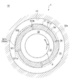
- FIGS. 1 to 5 are cross-sectional views showing one cross section in the axial direction of a floating bush bearing device according to an embodiment of the present invention.
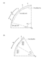
- FIG. 6A is an explanatory diagram for explaining the cross-sectional shapes of the land portion and the recessed portion in the floating bush bearing device according to the embodiment of the present invention.
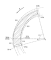
- FIG. 6B is an explanatory diagram for explaining the relative positions of the land portion and the recessed portion formed on the inner peripheral surface and the outer peripheral surface of the floating bush in the floating bush bearing device according to the embodiment of the present invention.
- a floating bush bearing device 1 (1A to 1E) according to an embodiment of the present invention is a device for rotatably supporting a rotating shaft 2. As shown in FIGS. And a bearing housing 4.
- the floating bush 3 is a cylindrical member having a bearing hole 33 through which the rotary shaft 2 is inserted.
- An oil film is formed by the lubricating oil supplied to the gap 10 between the rotary shaft 2 and the inner peripheral surface 31 of the floating bush 3, and the rotary shaft 2 is rotatably supported by the oil film formed in the gap 10. It is configured.
- the bearing housing 4 is a member that rotatably accommodates the floating bush 3.
- An oil film is formed by the lubricating oil supplied to the gap 20 between the outer peripheral surface 32 of the floating bush 3 and the inner peripheral surface 41 of the bearing housing 4, and the rotational direction R of the rotary shaft 2 is formed by the oil film formed in the gap 20. It is comprised so that the floating bush 3 which rotates with the rotating shaft 2 in the same direction may be supported rotatably.
- the cross section is formed to include a plurality of land portions 311, 321, 411 and a plurality of recess portions 312, 322, 412.
- the land portions 311, 321, 411 have a true arc shape which is a part of a perfect circle shape.
- the recessed portions 312, 322, and 412 are located at positions that are recessed from the land portions 311, 321, and 411.
- the depressions 312, 322, 412 are directed from the end portions 311 b, 321 b, 411 b of the land portions 311, 321, 411 opposite to the rotation direction R of the rotation shaft 2 in the direction opposite to the rotation direction R of the rotation shaft 2.
- the distance from the virtual circular lines 31a, 32a, 41a passing through the land portions 311, 321, 411 is increased.
- the land portions 311, 321, 411 having a true circular arc shape which is a part of a perfect circle shape can manage the tolerances smaller than those of the recessed portions 312, 322, 412. Therefore, according to such an embodiment, at least one of the inner peripheral surface 31 of the floating bush 3, the outer peripheral surface 32 of the floating bush 3, and the inner peripheral surface 41 of the bearing housing 4 is in a cross section in the axial direction.
- the recessed portions 312, 322, and 412 that are indented from the land portions 311, 321, and 411 are arranged so that the rotational shaft 2 extends from the end of the land portions 311, 321, and 411 opposite to the rotational direction R of the rotational shaft 2. In the direction opposite to the rotation direction R, the distance from the virtual circular lines 31a, 32a, 41a passing through the land portions 311, 321, 411 is increased. Due to the presence of such depressions 312, 322, 412, the gaps 10, 20 in the circumferential direction become non-uniform, and a lack of lubricating oil is induced in the portions where the gaps 10, 20 are large.
- At least one of the inner peripheral surface 31 of the floating bush 3, the outer peripheral surface 32 of the floating bush 3, and the inner peripheral surface 41 of the bearing housing 4 is in a cross section in the axial direction.
- the recessed portions 312, 322, and 412 are formed in an arc shape that is a part of a perfect circle shape, an elliptical shape, an oval shape, or the like.
- the numbers in the circumferential direction of the land portions 311, 321, 411 and the recessed portions 312, 322, 412 are not particularly limited.
- the shape of the recesses 312, 322, 412 is not limited to an arc shape. As shown in FIG. 6A (a), the shape may be a part of a polygon made up of a plurality of straight lines a to e, and formed from a single straight line f as shown in FIG. 6A (b). May be.
- the angle range indicating the region where the land portions 311, 321, 411 are formed is represented by ⁇ 1
- the angle range indicating the region where the recess portions 312, 322, 412 are formed is represented by ⁇ 2.
- the inner peripheral surface 31 of the floating bush 3 is the axial direction of the floating bush 3. Are formed so as to include the land portion 311 and the recessed portion 312 respectively.
- the land portion 311 is formed from the end portion 311 a on the rotation direction R side of the rotation shaft 2 to the end portion 311 b on the opposite side to the rotation direction R.
- the recess 312 is formed from the end 312 a on the rotation direction R side of the rotating shaft 2 to the end 312 b on the opposite side to the rotation direction R. Note that the end 311b opposite to the rotation direction R of the land 311 and the end 312a of the recess 312 on the rotation direction R side are at the same position.
- the gap 10 between the rotating shaft 2 and the land portion 311 of the inner peripheral surface 31 of the floating bush 3 is suppressed, Vibration stability can be improved.
- the lack of lubricating oil is induced in the portion where the gap 10 is large, thereby improving vibration stability. I can do it.
- the outer peripheral surface 32 of the floating bush 3 is in the axial direction of the floating bush 3. In one cross section, it is formed so as to include a land portion 321 and a hollow portion 322, respectively.
- the land portion 321 is formed from the end portion 321 a on the rotation direction R side of the rotation shaft 2 to the end portion 321 b on the opposite side to the rotation direction R.
- the recess 322 is formed from the end 322 a on the rotation direction R side of the rotating shaft 2 to the end 322 b on the opposite side to the rotation direction R. Note that the end 321b opposite to the rotation direction R of the land portion 321 and the end 322a of the recess 322 on the rotation direction R side are at the same position.
- asynchronous vibration caused by tolerances can be achieved. Can be suppressed and vibration stability can be improved. Further, since a portion where the gap 20 is large is formed between the land portion 321 of the outer peripheral surface 32 of the floating bush 3 and the inner peripheral surface 41 of the bearing housing 4, a lack of lubricating oil is induced in the portion where the gap 20 is large. Vibration stability can be improved.
- the inner peripheral surface 31 of the floating bush 3 is in a cross section in the axial direction of the floating bush 3.
- a land portion 311 and a hollow portion 312 are formed to be included.
- the outer peripheral surface 32 of the floating bush 3 is formed so as to include a land portion 321 and a recessed portion 322 in one cross section in the axial direction of the floating bush 3.
- the land part 311 of the internal peripheral surface 31 of the floating bush 3 and the land part 321 of the outer peripheral surface 32 of the floating bush 3 are formed in the area
- the recess 312 of the inner peripheral surface 31 of the floating bush 3 and the recess 322 of the outer peripheral surface 32 of the floating bush 3 are formed in regions overlapping each other in the circumferential direction.
- the land portion 311 and the land portion 321 are formed in regions overlapping each other in the circumferential direction” means a form as shown in FIG. 6B. That is, as shown in FIG. 6B, the angle range ⁇ 1 indicating the region where the land portion 311 is formed and the angle range ⁇ 1 indicating the region where the land portion 321 is formed have the same angle.
- the center point O of the land portion 311 having a true arc shape and the center point O of the land portion 321 having a true arc shape are at the same position.
- the center point O, the end 311a on the rotation direction R side of the land 311 and the end 321a on the rotation direction R side of the land 321 are located on the same straight line. Further, the center point O, the end 311b opposite to the rotation direction R of the land 311 and the end 321b opposite to the rotation direction R of the land 321 are located on the same straight line.
- the dent portion 312 and the dent portion 322 are formed in regions overlapping each other in the circumferential direction” means a form as shown in FIG. 6B. That is, as shown in FIG. 6B, the angle range ⁇ 2 indicating the region where the recess 321 is formed and the angle range ⁇ 2 indicating the region where the recess 322 is formed have the same angle.
- the center point O, the end 312a on the rotation direction R side of the recess 312 and the end 321a on the rotation direction R side of the recess 322 are located on the same straight line. Further, the center point O, the end 312b opposite to the rotation direction R of the recess 312 and the end 321b opposite to the rotation direction R of the recess 322 are located on the same straight line.
- the gaps 10 and 20 are large between the rotary shaft 2 and the inner peripheral surface 31 of the floating bush 3 and between the land portion 321 of the outer peripheral surface 32 of the floating bush 3 and the inner peripheral surface 41 of the bearing housing 4. Since a portion is formed, vibration stability can be improved by inducing a lack of lubricating oil in a portion where the gap is large.
- the part 322 is formed in a region overlapping with each other in the circumferential direction.
- the floating bush 3 is a cylindrical floating bush 3.
- An oil supply hole 34 penetrating the peripheral wall 3A is included.
- the end portions 311a and 321a on the rotation direction R side of the rotation shaft 2 in the land portions 311 and 321 or the rotation direction R of the rotation shaft 2 in the recess portions 312 and 322 are observed.
- an end portion 312b on the opposite direction side is included.
- the oil supply hole 34 is formed at a position overlapping the end portions 311a and 321a on the rotation direction R side of the rotation shaft 2 in the land portions 311 and 321 when viewed from the axial direction. That is, the oil supply hole 34 is formed at a position closest to the rotation direction R in the land portions 311 and 321.
- the oil supply hole 34 may be formed at a position overlapping the end portions 312b and 322b on the opposite side to the rotation direction R of the rotary shaft 2 in the recessed portions 312 and 322 when viewed from the axial direction. Good.
- the oil supply hole 34 may be formed at a position opposite to the rotation direction R in the recesses 312 and 322.
- four oil supply holes 34 are formed at equal intervals in the circumferential direction.
- the number of the oil supply holes 34 is not particularly limited.
- the oil supply hole 34 is formed at a position where the distance from the perfect circular lines 31a and 32a is the longest in the depressions 312 and 322, or in the vicinity thereof. Therefore, by forming the oil supply hole 34 at such a position, the flow rate of the lubricating oil flowing from the outer peripheral side of the floating bush 3 to the inner peripheral side of the floating bush 3 can be increased.
- the inner peripheral surface 41 of the bearing housing 4 is in a cross section in the axial direction of the bearing housing 4.
- a land portion 411 and a hollow portion 412 are formed to be included.
- the land portion 411 is formed from the end portion 411 a on the rotation direction R side of the rotation shaft 2 to the end portion 411 b on the opposite side to the rotation direction R.
- the depression 412 is formed from the end 412 a on the rotation direction R side of the rotation shaft 2 to the end 412 b on the opposite side to the rotation direction R. Note that the end portion 411b opposite to the rotation direction R of the land portion 411 and the end portion 412a of the recess portion 412 on the rotation direction R side are at the same position.
- asynchronous vibration caused by tolerances can be achieved. Can be suppressed and vibration stability can be improved. Further, since a portion where the gap 20 is large is formed between the inner peripheral surface 41 of the bearing housing 4 and the outer peripheral surface 32 of the floating bush 3, vibration stability is induced by inducing a lack of lubricating oil in the portion where the gap 20 is large. Can be increased.
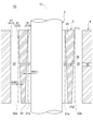
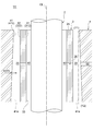
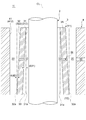
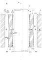
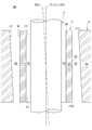
- FIGS. 7 to 12 are axial sectional views showing a section along the axial direction of the floating bush bearing device according to the embodiment of the present invention.
- the inner peripheral surface 31 of the floating bush 3 and the outer periphery of the floating bush 3 The land portions 311, 321, 411 and the recessed portions 312, 322, 412 formed in at least one of the surface 32 and the inner peripheral surface 41 of the bearing housing 4 are respectively axial directions of the bearing housing 4 or the floating bush 3. And continuously formed.
- the depressions 312, 322, 412 are formed such that the distance d (d 1, d 2, d 3) between the depressions 312, 322, 412 and the virtual perfect circular lines 31 a, 32 a changes in the axial direction. .
- virtual perfect circular lines 31a, 32a, and 41a passing through the land portions 311, 321, and 411 extend in parallel to the axis CL in the respective axial directions. Yes. That is, only the depressions 312, 322, and 412 are formed so that the distance d (d 1, d 2, d 3) with the perfect circular lines 31 a and 32 a changes in the axial direction, and the land portions 311, 321, The cross-sectional shape of 411 is not changed in the axial direction.
- the distance d (d1, d2, d3) between the hollow portions 312, 322, 412 and the virtual perfect circular lines 31a, 32a is formed to change in the axial direction. Due to the presence of such depressions 312, 322, 412, the gaps 10, 20 in the axial direction are not uniform, and a lack of lubricating oil is induced in the part where the gaps 10, 20 are large. Accordingly, at least one of the inner peripheral surface 31 of the floating bush 3, the outer peripheral surface 32 of the floating bush 3, and the inner peripheral surface 41 of the bearing housing 4 has such depressions 312, 322, and 412, thereby providing lubrication. Insufficient oil can be induced to improve vibration stability.
- the recesses 312, 322, 412 and the recesses 312, 322, 412 are imaginary.
- the distance d (d1, d2, d3) with the perfect circular lines 31a, 32a, 41a is formed so as to increase from the one end side Y1 in the axial direction toward the other end side Y2.
- the upper side of the drawing is the one end side Y1, and the lower side of the drawing is the other end side Y2.
- the distance d1 between the recessed portion 312 and the virtual perfect circular line 31a is changed from one end side Y1 in the axial direction to the other end side Y2. It is formed so as to become larger.
- the distance d2 between the recessed portion 322 and the virtual perfect circular line 32a is the one end side Y1 in the axial direction. It is formed so that it may become large toward the other end side Y2.
- the distance d3 between the recessed portion 412 and the virtual perfect circular line 41a is from the one end side Y1 in the axial direction toward the other end side Y2. It is formed to be large.
- the gaps 10 and 20 in the axial direction become non-uniform, and a lack of lubricating oil is induced in a portion where the gaps 10 and 20 are large. Therefore, the lack of lubricating oil can be induced to improve the vibration stability.
- the inner peripheral surface 31 of the floating bush 3 has a land portion 311 and a depression in one cross section in the axial direction of the floating bush 3.
- Each part 312 is formed.
- the outer peripheral surface 32 of the floating bush 3 is formed so as to include a land portion 321 and a recessed portion 322 in one cross section in the axial direction of the floating bush 3.
- each of the hollow part 312 of the inner peripheral surface 31 of the floating bush 3 and the hollow part 322 of the outer peripheral surface 32 of the floating bush 3 is the distance d between the hollow parts 312 and 322 and the virtual perfect circular lines 31a and 32a.
- D1, d2) is formed so as to increase from one end side Y1 in the axial direction toward the other end side Y2.
- the inner peripheral surface 31 of the floating bush 3 has a land portion 311 and a depression in one cross section in the axial direction of the floating bush 3.
- Each part 312 is formed.
- the outer peripheral surface 32 of the floating bush 3 is formed so as to include a land portion 321 and a recessed portion 322 in one cross section in the axial direction of the floating bush 3.
- the depression 312 of the inner peripheral surface 31 of the floating bush 3 is such that the distance d1 between the depression 312 and the virtual perfect circular line 31a increases from one end Y1 in the axial direction toward the other end Y2.
- the hollow portion 322 of the outer peripheral surface 32 of the floating bush 3 is formed such that the distance d2 between the hollow portion 322 and the virtual perfect circular line 32a increases from the other end side Y2 in the axial direction toward the one end side Y1.
- the floating bush 3 in the floating bush bearing device 1 (1J, 1K), has an oil supply hole 34 penetrating the peripheral wall 3A of the cylindrical floating bush 3.
- the inner peripheral surface 31 of the floating bush 3 is formed so as to include a land portion 311 and a recessed portion 312 in one cross section in the axial direction of the floating bush 3.
- the depression 312 of the inner peripheral surface 31 of the floating bush 3 is such that the distance d1 between the depression 312 and the virtual perfect circular line 31a is directed from the one end Y1 and the other end Y2 in the axial direction toward the oil supply hole 34. To be large.
- the compressor rotor 102 is disposed in the intake passage of the engine.
- the turbine rotor 104 is disposed in the exhaust passage of the engine. Then, the turbine rotor 104 is rotated by the exhaust gas discharged from the engine, and the compressor rotor 102 is coaxially driven along with this, so that the air flowing through the intake passage is compressed and the supercharged air is supplied to the engine. Is done.
- the supercharger 100 of this invention is not limited to the turbocharger 100a mentioned above.
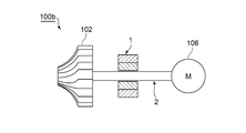
- an electric motor 106 may be provided instead of the turbine rotor 104, and the electric turbocharger 100 b may be configured to be driven by the compressor rotor 102 when the rotating shaft 2 is rotated by the electric motor 106. It is.
- At least one embodiment of the present invention is suitably used as a floating bush bearing device that rotatably supports a rotating shaft, for example, in a small turbocharger mounted on an automobile engine.
Landscapes
- Engineering & Computer Science (AREA)
- General Engineering & Computer Science (AREA)
- Mechanical Engineering (AREA)
- Chemical & Material Sciences (AREA)
- Oil, Petroleum & Natural Gas (AREA)
- Physics & Mathematics (AREA)
- Fluid Mechanics (AREA)
- Sliding-Contact Bearings (AREA)
- Supercharger (AREA)
Abstract
Description
回転軸を回転可能に支持する浮動ブッシュ軸受装置において、
前記回転軸が挿通される軸受穴を有する円筒状の浮動ブッシュと、
前記浮動ブッシュを回転可能に収容する軸受ハウジングと、を備え、
前記浮動ブッシュの内周面、前記浮動ブッシュの外周面、及び前記軸受ハウジングの内周面、の少なくとも一つは、その軸方向における一断面において、真円形状の一部である真円弧状を有する複数のランド部、及び前記ランド部よりも凹んだ位置にある複数の窪み部であって、前記ランド部における前記回転軸の回転方向と反対側の端部から前記回転軸の回転方向と反対方向に向かって、前記ランド部を通過する仮想の真円形状線との距離が大きくなるように構成される複数の窪み部、を含むように形成される。
回転軸と、
回転軸の一端部に連結されるコンプレッサホイールと、
上記(1)から(14)の何れかに記載に浮動ブッシュ軸受装置と、を備える。
例えば、「ある方向に」、「ある方向に沿って」、「平行」、「直交」、「中心」、「同心」或いは「同軸」等の相対的或いは絶対的な配置を表す表現は、厳密にそのような配置を表すのみならず、公差、若しくは、同じ機能が得られる程度の角度や距離をもって相対的に変位している状態も表すものとする。
例えば、「同一」、「等しい」及び「均質」等の物事が等しい状態であることを表す表現は、厳密に等しい状態を表すのみならず、公差、若しくは、同じ機能が得られる程度の差が存在している状態も表すものとする。
例えば、四角形状や円筒形状等の形状を表す表現は、幾何学的に厳密な意味での四角形状や円筒形状等の形状を表すのみならず、同じ効果が得られる範囲で、凹凸部や面取り部等を含む形状も表すものとする。
一方、一の構成要素を「備える」、「具える」、「具備する」、「含む」、又は、「有する」という表現は、他の構成要素の存在を除外する排他的な表現ではない。
また、以下の説明において、同じ構成には同じ符号を付してその詳細な説明を省略する場合がある。
本発明の一実施形態にかかる浮動ブッシュ軸受装置1(1A~1E)は、回転軸2を回転可能に支持するための装置であり、図1~図5に示すように、浮動ブッシュ3と、軸受ハウジング4と、を備えている。
また、図示した実施形態では、給油孔34は、周方向に等間隔に4つ形成されている。ただし、給油孔34の数は特に限定されない。
幾つか実施形態では、図7~図12に示すように、浮動ブッシュ軸受装置1(1F,1G,1H,1I,1J,1K)において、浮動ブッシュ3の内周面31、浮動ブッシュ3の外周面32、及び軸受ハウジング4の内周面41、の少なくとも一つに形成されるランド部311,321,411および窪み部312,322,412は、軸受ハウジング4または浮動ブッシュ3の各々の軸方向に亘って連続して形成される。そして、窪み部312,322,412は、窪み部312,322,412と仮想の真円形状線31a,32aとの距離d(d1,d2,d3)が軸方向において変化するように形成される。
2 回転軸
3 浮動ブッシュ
31 内周面
32 外周面
33 軸受穴
34 給油孔
3A 周壁
4 軸受ハウジング
41 内周面
44 潤滑油供給穴
10,20 隙間
31a,32a,41a 真円形状線
311,321,411 ランド部
312,322,412 窪み部
100a ターボチャージャ
100b 電動過給機
102 コンプレッサロータ
104 タービンロータ
106 電動機
Claims (15)
- 回転軸を回転可能に支持する浮動ブッシュ軸受装置において、
前記回転軸が挿通される軸受穴を有する円筒状の浮動ブッシュと、
前記浮動ブッシュを回転可能に収容する軸受ハウジングと、を備え、
前記浮動ブッシュの内周面、前記浮動ブッシュの外周面、及び前記軸受ハウジングの内周面、の少なくとも一つは、その軸方向における一断面において、真円形状の一部である真円弧状を有する複数のランド部、及び前記ランド部よりも凹んだ位置にある複数の窪み部であって、前記ランド部における前記回転軸の回転方向と反対側の端部から前記回転軸の回転方向と反対方向に向かって、前記ランド部を通過する仮想の真円形状線との距離が大きくなるように構成される複数の窪み部、を含むように形成される
浮動ブッシュ軸受装置。 - 前記浮動ブッシュの内周面は、前記浮動ブッシュの軸方向における一断面において、前記ランド部および前記窪み部を夫々含むように形成される
請求項1に記載の浮動ブッシュ軸受装置。 - 前記浮動ブッシュの外周面は、前記浮動ブッシュの軸方向における一断面において、前記ランド部および前記窪み部を夫々含むように形成される
請求項1又は2に記載の浮動ブッシュ軸受装置。 - 前記浮動ブッシュの内周面は、前記浮動ブッシュの軸方向における一断面において、前記ランド部および前記窪み部を夫々含むように形成され、
前記浮動ブッシュの外周面は、前記浮動ブッシュの軸方向における一断面において、前記ランド部および前記窪み部を夫々含むように形成され、
前記浮動ブッシュの内周面の前記ランド部、及び前記浮動ブッシュ軸受の外周面の前記ランド部は、周方向において互いに重複する領域に形成され、
前記浮動ブッシュの内周面の前記窪み部、及び前記浮動ブッシュ軸受の外周面の前記窪み部は、周方向において互いに重複する領域に形成される
請求項1から3の何れか一項に記載の浮動ブッシュ軸受装置。 - 前記浮動ブッシュは、前記円筒状の浮動ブッシュの周壁を貫通する給油孔を含み、
前記給油孔は、軸方向から視認した場合において、前記ランド部における前記回転軸の回転方向側の端部、又は前記窪み部における前記回転軸の回転方向と反対方向側の端部、と重複する位置に形成される、
請求項2から4の何れか一項に記載の浮動ブッシュ軸受装置。 - 前記軸受ハウジングの内周面は、前記軸受ハウジングの軸方向における一断面において、前記ランド部および前記窪み部を夫々含むように形成される
請求項1から5の何れか一項に記載の浮動ブッシュ軸受装置。 - 前記浮動ブッシュの内周面、前記浮動ブッシュの外周面、及び前記軸受ハウジングの内周面、の少なくとも一つに形成される前記ランド部および前記窪み部は、前記軸受ハウジングまたは前記浮動ブッシュの各々の軸方向に亘って連続して形成され、
前記窪み部は、前記窪み部と前記仮想の真円形状線との距離が軸方向において変化するように形成される
請求項1から6の何れか一項に記載の浮動ブッシュ軸受装置。 - 前記窪み部は、前記窪み部と前記仮想の真円形状線との距離が、軸方向の一端側から他端側に向かって大きくなるように形成される
請求項7に記載の浮動ブッシュ軸受装置。 - 前記浮動ブッシュの内周面は、前記浮動ブッシュの軸方向における一断面において、前記ランド部および前記窪み部を夫々含むように形成され、
前記浮動ブッシュの外周面は、前記浮動ブッシュの軸方向における一断面において、前記ランド部および前記窪み部を夫々含むように形成され、
前記浮動ブッシュの内周面の前記窪み部、及び前記浮動ブッシュの外周面の前記窪み部の各々は、前記窪み部と前記仮想の真円形状線との距離が、軸方向の一端側から他端側に向かって大きくなるように形成される
請求項7又は8に記載の浮動ブッシュ軸受装置。 - 前記浮動ブッシュの内周面は、前記浮動ブッシュの軸方向における一断面において、前記ランド部および前記窪み部を夫々含むように形成され、
前記浮動ブッシュの外周面は、前記浮動ブッシュの軸方向における一断面において、前記ランド部および前記窪み部を夫々含むように形成され、
前記浮動ブッシュの内周面の前記窪み部は、前記窪み部と前記仮想の真円形状線との距離が、軸方向の一端側から他端側に向かって大きくなるように形成され、
前記浮動ブッシュの外周面の前記窪み部は、前記窪み部と前記仮想の真円形状線との距離が、軸方向の他端側から一端側に向かって大きくなるように形成される
請求項7又は8に記載の浮動ブッシュ軸受装置。 - 前記浮動ブッシュは、前記円筒状の浮動ブッシュの周壁を貫通する給油孔を含み、
前記浮動ブッシュの内周面は、前記浮動ブッシュの軸方向における一断面において、前記ランド部および前記窪み部を夫々含むように形成され、
前記浮動ブッシュの内周面の前記窪み部は、前記窪み部と前記仮想の真円形状線との距離が、軸方向の一端側および他端側から前記給油孔に向かって大きくなるように形成される
請求項7に記載の浮動ブッシュ軸受装置。 - 前記浮動ブッシュは、前記円筒状の浮動ブッシュの周壁を貫通する給油孔を含み、
前記浮動ブッシュの外周面は、前記浮動ブッシュの軸方向における一断面において、前記ランド部および前記窪み部を夫々含むように形成され、
前記浮動ブッシュの外周面の前記窪み部は、前記窪み部と前記仮想の真円形状線との距離が、軸方向の一端側および他端側から前記給油孔に向かって大きくなるように形成される
請求項7又は11に記載の浮動ブッシュ軸受装置。 - 前記浮動ブッシュの内周面における中心線が、前記回転軸の中心線に対して傾斜しているか、又は前記浮動ブッシュの外周面における中心線が、前記軸受ハウジングの内周面における中心線に対して傾斜している
請求項1から6の何れか一項に記載の浮動ブッシュ軸受装置。 - 前記浮動ブッシュの内周面に形成される前記窪み部は、真円形状を有する前記浮動ブッシュの内周面を加工することで形成されるか、又は、
前記浮動ブッシュの外周面に形成される前記窪み部は、真円形状を有する前記浮動ブッシュの外周面を加工することで形成されるか、又は、
前記軸受ハウジングの内周面に形成される前記窪み部は、真円形状を有する前記軸受ハウジングの内周面を加工することで形成される
請求項1から13の何れか一項に記載の浮動ブッシュ軸受装置。 - 回転軸と、
前記回転軸の一端部に連結されるコンプレッサホイールと、
請求項1から14の何れか一項に記載に浮動ブッシュ軸受装置と、
を備える過給機。
Priority Applications (5)
| Application Number | Priority Date | Filing Date | Title |
|---|---|---|---|
| CN201580072623.2A CN107110200B (zh) | 2015-02-10 | 2015-02-10 | 浮动轴瓦轴承装置及具备其的增压机 |
| JP2016574557A JP6370933B2 (ja) | 2015-02-10 | 2015-02-10 | 浮動ブッシュ軸受装置及びこれを備える過給機 |
| PCT/JP2015/053678 WO2016129060A1 (ja) | 2015-02-10 | 2015-02-10 | 浮動ブッシュ軸受装置及びこれを備える過給機 |
| US15/541,173 US10288112B2 (en) | 2015-02-10 | 2015-02-10 | Floating bush bearing device and supercharger provided with the same |
| EP15881935.9A EP3258123B1 (en) | 2015-02-10 | 2015-02-10 | Floating bush bearing device and supercharger provided with same |
Applications Claiming Priority (1)
| Application Number | Priority Date | Filing Date | Title |
|---|---|---|---|
| PCT/JP2015/053678 WO2016129060A1 (ja) | 2015-02-10 | 2015-02-10 | 浮動ブッシュ軸受装置及びこれを備える過給機 |
Publications (1)
| Publication Number | Publication Date |
|---|---|
| WO2016129060A1 true WO2016129060A1 (ja) | 2016-08-18 |
Family
ID=56614384
Family Applications (1)
| Application Number | Title | Priority Date | Filing Date |
|---|---|---|---|
| PCT/JP2015/053678 Ceased WO2016129060A1 (ja) | 2015-02-10 | 2015-02-10 | 浮動ブッシュ軸受装置及びこれを備える過給機 |
Country Status (5)
| Country | Link |
|---|---|
| US (1) | US10288112B2 (ja) |
| EP (1) | EP3258123B1 (ja) |
| JP (1) | JP6370933B2 (ja) |
| CN (1) | CN107110200B (ja) |
| WO (1) | WO2016129060A1 (ja) |
Cited By (2)
| Publication number | Priority date | Publication date | Assignee | Title |
|---|---|---|---|---|
| JP2019157912A (ja) * | 2018-03-08 | 2019-09-19 | 三菱重工業株式会社 | 過給機 |
| US12018714B2 (en) | 2020-04-06 | 2024-06-25 | Ihi Corporation | Multilobe bearing |
Families Citing this family (4)
| Publication number | Priority date | Publication date | Assignee | Title |
|---|---|---|---|---|
| WO2019126615A1 (en) * | 2017-12-22 | 2019-06-27 | Borgwarner Inc. | Turbocharger for an internal combustion engine with a hydrodynamic floating bearing |
| DE112018007702T5 (de) * | 2018-06-28 | 2021-03-04 | Borgwarner Inc. | Lagerelement mit einem glatten durchgehenden profil |
| CN110594287A (zh) * | 2019-09-17 | 2019-12-20 | 福建福清核电有限公司 | 一种主泵一体式三液槽径向水导轴瓦 |
| JP2026523012A (ja) * | 2023-07-17 | 2026-07-09 | レンク・ゲーエムベーハー | 流体力学的滑り軸受 |
Citations (4)
| Publication number | Priority date | Publication date | Assignee | Title |
|---|---|---|---|---|
| JPS59168020U (ja) * | 1983-04-26 | 1984-11-10 | 三菱重工業株式会社 | 軸受装置 |
| JPH01193409A (ja) * | 1988-01-26 | 1989-08-03 | Ishikawajima Harima Heavy Ind Co Ltd | フローテイングメタルを備えた軸受 |
| JPH08219148A (ja) * | 1995-02-16 | 1996-08-27 | Mitsubishi Heavy Ind Ltd | 浮動ブッシュ軸受 |
| JP2009167872A (ja) * | 2008-01-15 | 2009-07-30 | Toyota Motor Corp | 過給機 |
Family Cites Families (23)
| Publication number | Priority date | Publication date | Assignee | Title |
|---|---|---|---|---|
| US3680932A (en) * | 1970-09-10 | 1972-08-01 | Westinghouse Electric Corp | Stable journal bearing |
| JPS58142014A (ja) | 1982-02-17 | 1983-08-23 | Hitachi Ltd | 浮動ブツシユ軸受 |
| JPS58149415A (ja) * | 1982-02-26 | 1983-09-05 | Hitachi Ltd | 制振軸受 |
| JPS6130722U (ja) * | 1984-07-30 | 1986-02-24 | 株式会社日立製作所 | 制振軸受 |
| US4747705A (en) * | 1987-06-26 | 1988-05-31 | United Technologies Corporation | Power shaped multipad hydrodynamic journal bearing |
| US5752318A (en) * | 1995-12-06 | 1998-05-19 | Ingersoll-Rand Company | Hydrodynamic bearing and method |
| WO1997041362A1 (en) * | 1996-04-30 | 1997-11-06 | Sumitomo Electric Industries, Ltd. | Dynamic-pressure gas bearing structure, method of producing the same and method of using it |
| JPH11283321A (ja) | 1998-03-31 | 1999-10-15 | Hitachi Ltd | 高い衝撃耐久性能を有するディスク駆動装置及び磁気ディスク装置 |
| JP3962168B2 (ja) | 1998-12-01 | 2007-08-22 | 日本電産サンキョー株式会社 | 動圧軸受装置及びその製造方法 |
| JP4215365B2 (ja) * | 1999-02-16 | 2009-01-28 | 株式会社日立グローバルストレージテクノロジーズ | スピンドルモータとそれを用いた磁気ディスク装置 |
| US20030132678A1 (en) * | 2000-03-10 | 2003-07-17 | Samsung Electro-Mechanics Co., Ltd. | Sintered oilless bearing and motor using the same |
| CN1940322A (zh) * | 2005-09-30 | 2007-04-04 | 富准精密工业(深圳)有限公司 | 流体动压轴承 |
| JP2009030474A (ja) * | 2007-07-25 | 2009-02-12 | Toyota Motor Corp | ターボチャージャの軸受構造 |
| US8646979B2 (en) * | 2007-09-13 | 2014-02-11 | Elka Precision, Llc | Hybrid hydro (air) static multi-recess journal bearing |
| JP2009174466A (ja) * | 2008-01-25 | 2009-08-06 | Toyota Motor Corp | ターボチャージャの軸受構造 |
| US8328506B2 (en) * | 2008-12-04 | 2012-12-11 | General Electric Company | Optimized turbocharger bearing system |
| US8790066B2 (en) * | 2010-02-18 | 2014-07-29 | Honeywell International Inc. | Multi-lobe semi-floating journal bearing |
| JP2013520759A (ja) * | 2010-02-23 | 2013-06-06 | ラムバス・インコーポレーテッド | Dramの電力および性能を動的にスケーリングするための方法および回路 |
| JP5535976B2 (ja) * | 2011-03-29 | 2014-07-02 | 三菱重工業株式会社 | ターボチャージャおよびフローティングブッシュ製造方法 |
| EP3098465B1 (en) * | 2012-12-19 | 2019-10-02 | Mitsubishi Heavy Industries, Ltd. | Floating bush bearing device and supercharger including the same |
| JP5730436B2 (ja) * | 2012-12-19 | 2015-06-10 | 三菱重工業株式会社 | 浮動ブッシュ軸受装置及びこれを備える過給機 |
| JP5477930B1 (ja) | 2013-07-31 | 2014-04-23 | 株式会社中村製作所 | 低振動形フローティングメタルベアリング |
| DE102014213330A1 (de) * | 2014-07-09 | 2016-01-14 | Bosch Mahle Turbo Systems Gmbh & Co. Kg | Ladeeinrichtung |
-
2015
- 2015-02-10 US US15/541,173 patent/US10288112B2/en active Active
- 2015-02-10 JP JP2016574557A patent/JP6370933B2/ja active Active
- 2015-02-10 WO PCT/JP2015/053678 patent/WO2016129060A1/ja not_active Ceased
- 2015-02-10 EP EP15881935.9A patent/EP3258123B1/en active Active
- 2015-02-10 CN CN201580072623.2A patent/CN107110200B/zh active Active
Patent Citations (4)
| Publication number | Priority date | Publication date | Assignee | Title |
|---|---|---|---|---|
| JPS59168020U (ja) * | 1983-04-26 | 1984-11-10 | 三菱重工業株式会社 | 軸受装置 |
| JPH01193409A (ja) * | 1988-01-26 | 1989-08-03 | Ishikawajima Harima Heavy Ind Co Ltd | フローテイングメタルを備えた軸受 |
| JPH08219148A (ja) * | 1995-02-16 | 1996-08-27 | Mitsubishi Heavy Ind Ltd | 浮動ブッシュ軸受 |
| JP2009167872A (ja) * | 2008-01-15 | 2009-07-30 | Toyota Motor Corp | 過給機 |
Non-Patent Citations (1)
| Title |
|---|
| See also references of EP3258123A4 * |
Cited By (2)
| Publication number | Priority date | Publication date | Assignee | Title |
|---|---|---|---|---|
| JP2019157912A (ja) * | 2018-03-08 | 2019-09-19 | 三菱重工業株式会社 | 過給機 |
| US12018714B2 (en) | 2020-04-06 | 2024-06-25 | Ihi Corporation | Multilobe bearing |
Also Published As
| Publication number | Publication date |
|---|---|
| EP3258123B1 (en) | 2018-09-05 |
| EP3258123A4 (en) | 2017-12-20 |
| CN107110200B (zh) | 2019-05-14 |
| US20180258984A1 (en) | 2018-09-13 |
| US10288112B2 (en) | 2019-05-14 |
| EP3258123A1 (en) | 2017-12-20 |
| JP6370933B2 (ja) | 2018-08-08 |
| CN107110200A (zh) | 2017-08-29 |
| JPWO2016129060A1 (ja) | 2017-08-10 |
Similar Documents
| Publication | Publication Date | Title |
|---|---|---|
| JP6370933B2 (ja) | 浮動ブッシュ軸受装置及びこれを備える過給機 | |
| US9188159B2 (en) | Half thrust bearing and bearing device | |
| CN104813044B (zh) | 浮动衬套轴承装置以及具有该浮动衬套轴承装置的增压器 | |
| JP5082477B2 (ja) | 浮動ブッシュ軸受構造 | |
| WO2012132586A1 (ja) | ターボチャージャおよびフローティングブッシュ製造方法 | |
| JP2011153668A (ja) | 軸受装置 | |
| JP6095233B2 (ja) | 内燃機関のクランク軸用スラスト軸受及び軸受装置 | |
| JPWO2015015599A1 (ja) | 低振動形フローティングメタルベアリング | |
| JP2014062557A (ja) | 軸受装置 | |
| CN105917128B (zh) | 液力滑动轴承 | |
| JP2016191465A (ja) | 軸受装置及び排気ガスターボチャージャー | |
| JP4969531B2 (ja) | 浮動ブッシュ軸受 | |
| JP2020537096A (ja) | 排気ガス式過給機 | |
| JP2010116944A (ja) | 浮動ブッシュ軸受式の軸受装置及びこれを備える内燃機関の過給機 | |
| US20120155793A1 (en) | Bearing arrangement for high-speed shafts of machines | |
| KR20200041818A (ko) | 풀 플로팅 베어링 및 이를 포함하는 터보차저 | |
| JP2010133530A (ja) | 軸受構造及び該軸受構造を備えた過給機 | |
| JP2016003631A (ja) | ベーンポンプ | |
| US11319835B2 (en) | Turbocharger for an internal combustion engine with a hydrodynamic floating bearing | |
| JP7831149B2 (ja) | 回転機械 | |
| JPS5999112A (ja) | すべり軸受 | |
| CN106195005B (zh) | 一种刀筒回转式回转刀横切刀辊 | |
| JP2015206410A (ja) | 転がり軸受 | |
| JP2023110644A (ja) | 内燃機関 | |
| JP2008215086A (ja) | ターボチャージャの軸受構造 |
Legal Events
| Date | Code | Title | Description |
|---|---|---|---|
| 121 | Ep: the epo has been informed by wipo that ep was designated in this application |
Ref document number: 15881935 Country of ref document: EP Kind code of ref document: A1 |
|
| ENP | Entry into the national phase |
Ref document number: 2016574557 Country of ref document: JP Kind code of ref document: A |
|
| WWE | Wipo information: entry into national phase |
Ref document number: 15541173 Country of ref document: US |
|
| REEP | Request for entry into the european phase |
Ref document number: 2015881935 Country of ref document: EP |
|
| NENP | Non-entry into the national phase |
Ref country code: DE |