WO2016129088A1 - Dispositif d'émission, dispositif de réception, et système d'émission et de réception - Google Patents
Dispositif d'émission, dispositif de réception, et système d'émission et de réception Download PDFInfo
- Publication number
- WO2016129088A1 WO2016129088A1 PCT/JP2015/053870 JP2015053870W WO2016129088A1 WO 2016129088 A1 WO2016129088 A1 WO 2016129088A1 JP 2015053870 W JP2015053870 W JP 2015053870W WO 2016129088 A1 WO2016129088 A1 WO 2016129088A1
- Authority
- WO
- WIPO (PCT)
- Prior art keywords
- unit
- data
- transmission
- bits
- parallel
- Prior art date
- Legal status (The legal status is an assumption and is not a legal conclusion. Google has not performed a legal analysis and makes no representation as to the accuracy of the status listed.)
- Ceased
Links
Images


Classifications
-
- G—PHYSICS
- G09—EDUCATION; CRYPTOGRAPHY; DISPLAY; ADVERTISING; SEALS
- G09G—ARRANGEMENTS OR CIRCUITS FOR CONTROL OF INDICATING DEVICES USING STATIC MEANS TO PRESENT VARIABLE INFORMATION
- G09G5/00—Control arrangements or circuits for visual indicators common to cathode-ray tube indicators and other visual indicators
-
- H—ELECTRICITY
- H04—ELECTRIC COMMUNICATION TECHNIQUE
- H04L—TRANSMISSION OF DIGITAL INFORMATION, e.g. TELEGRAPHIC COMMUNICATION
- H04L25/00—Baseband systems
- H04L25/38—Synchronous or start-stop systems, e.g. for Baudot code
- H04L25/40—Transmitting circuits; Receiving circuits
- H04L25/49—Transmitting circuits; Receiving circuits using code conversion at the transmitter; using predistortion; using insertion of idle bits for obtaining a desired frequency spectrum; using three or more amplitude levels ; Baseband coding techniques specific to data transmission systems
Definitions
- the present invention relates to a transmission device, a reception device, and a transmission / reception system, and more particularly to a technique effective in improving reliability in video transmission.
- HDMI High-Definition Multimedia Interface
- This HDMI (registered trademark) interface standard is disclosed in Non-Patent Document 1.
- Patent Document 1 states that “expansion beyond the maximum value in the current standards such as 15 Gbps and 20 Gbps is required in the future”, so “maintaining compatibility of connectors (plugs and receptacles)” On the other hand, it is described that “the current number of three data differential line pairs is increased to four or more. In accordance with this, the data rate is increased by the number of lanes for transmitting data”.
- a word separation means for separating N bits of digital data (N is a positive integer) into upper m bits (m is a positive integer, N> m) and lower (N ⁇ m) bits;
- Upper recording signal forming means for extracting a signal representing a value for each bit of the upper m bits
- lower recording signal forming means for extracting a signal representing a value for each bit of the lower (Nm) bits
- the amplitude of the signal of the upper bit is made larger than the amplitude of the signal of the lower bit and synthesized for each bit.
- a multi-valued signal synthesizing unit that multi-values the signal and transmits the multi-valued signal synthesized by the multi-valued signal synthesizing unit.
- JP 2012-85067 A Japanese Patent No. 3024132
- HDMI is required to transmit a large amount of data such as 4K / 8K at high speed.
- HDMI supports high-speed data transmission by increasing the frequency of the data transmission clock.
- increasing the frequency of the data transmission clock increases the high-frequency loss of the HDMI cable, which may impair the reliability of data transmission.
- An object of the present invention is to provide a technique capable of ensuring reliability in multi-level serial transmission of video data.
- a typical transmission apparatus includes a selector, a first scramble unit, a first encoding unit, a second scramble unit, a second encoding unit, and a multi-level output unit.
- the selector sorts the video data into an upper bit group and a lower bit group.
- the first scrambler scrambles the upper bit group assigned by the selector.
- the first encoding unit encodes the data scrambled by the first scramble unit.
- the second scrambler scrambles the lower bit group assigned by the selector.
- the second encoding unit encodes the data scrambled by the second scramble unit.
- the multi-level output unit multi-values each bit of the data encoded by the first encoding unit by assigning at least twice the weight of each bit of the data encoded by the second encoding unit. Serial output.
- the second encoding unit includes a cumulative disparity of the code data encoded by the first encoding unit, a cumulative disparity of the code data encoded by the second encoding unit, and the first encoding.
- the code data is determined and output from the disparity of the code data determined by the unit.
- the first encoding unit selects code data so that the absolute value of the accumulated disparity of the code data output from the first encoding unit is small
- the second encoding unit selects the first code.
- a code is added so that the absolute value of the total disparity is reduced by adding the cumulative disparity of the code data output by the second encoding unit to the numerical value obtained by multiplying the cumulative disparity output by the encoding unit by a value equal to the weight. Determine and output the data.
- a typical receiving apparatus includes a multi-value input unit, a first serial-parallel conversion unit, a first decoding unit, a first descrambling unit, a second serial-parallel conversion unit, a second decoding unit, There are two descrambling parts and a composite part.
- the multi-level input unit restores the multi-level data in which the received upper bits are added with a weight at least twice that of the lower bits to the upper bits and the lower bits.
- the first serial-parallel conversion unit parallelizes the upper bits restored by the multi-value input unit and converts them into parallel data.
- the first decoding unit decodes the parallel data parallelized by the first serial-parallel conversion unit.
- the first descrambling unit descrambles the data decoded by the first decoding unit.
- the second serial-parallel conversion unit parallelizes the lower bits restored by the multi-value input unit and converts them into parallel data.
- the second decoding unit decodes the parallel data parallelized by the second serial-parallel conversion unit.
- the second descrambling unit descrambles the data decoded by the second decoding unit.
- the composite unit generates video data from the descrambled data output from the first descrambling unit and the second descrambling unit.
- the encryption / decryption unit performs encryption / decryption of the video data generated by the composite unit.
- the composite unit composites the data scrambled by the first scramble release unit and the second scramble release unit, rearranges them into input units handled by the encryption / decryption unit, and outputs them.
- the receiving apparatus includes an error detection circuit that detects a transmission error of parallel data when the first decoding unit and the second decoding unit decode parallel data.
- the error detection circuit estimates parallel data input to the first decoding unit and the second decoding unit from the data decoded by the first decoding unit and the second decoding unit, respectively.
- the first serial-to-parallel conversion unit and the second serial-to-parallel conversion unit detect a transmission error from the difference from the parallel data respectively parallelized.
- FIG. 3 is an explanatory diagram illustrating an example of a configuration in a transmission / reception system according to Embodiment 1.
- FIG. It is explanatory drawing which shows an example of a structure in the transmission part which the transmission apparatus of FIG. 1 has, and the reception part which a reception apparatus has. It is explanatory drawing which showed an example of control of the accumulation disparity by the polarity control part of FIG.
- FIG. 10 is an explanatory diagram showing an example of 10-bit deep color transmission timing in the transmission / reception system according to the second embodiment. It is explanatory drawing which shows an example of the transmission waveform which can extract the clock by this Embodiment 3.
- FIG. It is explanatory drawing which shows an example of the bit arrangement
- FIG. 10 is an explanatory diagram illustrating an example of transmission timing of video data of three primary color video signals RGB according to a fourth embodiment.
- FIG. 20 is an explanatory diagram illustrating an example of transmission timing of video data of three primary color signals according to a fifth embodiment.
- FIG. 20 is an explanatory diagram illustrating an example of transmission timing of video data of three primary color signals according to a sixth embodiment.
- FIG. 20 is an explanatory diagram illustrating an example of transmission timing of video data of three primary color signals according to a seventh embodiment.
- the constituent elements are not necessarily indispensable unless otherwise specified and apparently essential in principle. Needless to say.
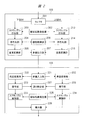
- FIG. 1 is an explanatory diagram showing an example of the configuration of the transmission / reception system according to the first embodiment.
- the transmission / reception system has a configuration having a transmission device 10 as a source device and a reception device 15 as a sink device.
- the transmission device 10 is, for example, a player that reproduces a video recording medium such as an STB (Set Top Box), an optical disc or an HDD (Hard Disc Drive), a video camera, a smartphone, or a tablet PC (Personal Computer).
- the receiving device 15 is, for example, a television or a monitor.
- the transmission device 10 and the reception device 15 are connected by a transmission cable such as HDMI.
- a transmission cable such as HDMI.
- a connection using HDMI will be described as an example.
- the transmission apparatus 10 includes a signal source 101, an encryption unit 102, a transmission unit 103, a CP (Content Protection) processing unit 104, a CPU (Central Processing Unit) 105, an EDID (Extended Display Identification Data) reading unit 106, a detection unit 107, The power supply unit 108, the CEC (Consumer Electronics Control) unit 109, the setting storage unit 110, and the HEAC (HDMI Ethernet and Audio Audio return Channel) unit 111 are included.
- CP Content Protection
- CPU Central Processing Unit
- EDID Extended Display Identification Data
- the power supply unit 108, the CEC (Consumer Electronics Control) unit 109, the setting storage unit 110, and the HEAC (HDMI Ethernet and Audio Audio return Channel) unit 111 are included.
- the receiving device 15 includes a display unit 151, an encryption / decryption unit 152, a reception unit 153, a CP processing unit 154, a CPU 155, an EDID storage unit 156, a control unit 157, a CEC unit 159, and a HEAC unit 160.
- the transmission device 10 is controlled by the CPU 105.
- the receiving device 15 is controlled by the CPU 155.
- the CPU 105 and the CPU 155 are operated by a user via an MMI (Man-Machine Interface) device including a remote operation device (not shown) attached to the transmission device 10 or the reception device 15. Further, the transmission device 10 and the reception device 15 are connected by the HDMI cable 200 as described above.
- MMI Man-Machine Interface
- the signal source 101 is a video signal source such as an external video input terminal, a DVD (Digital Versatile Disc), or a broadcast receiving unit, and outputs the video signal to the encryption unit 102.
- a video signal source such as an external video input terminal, a DVD (Digital Versatile Disc), or a broadcast receiving unit, and outputs the video signal to the encryption unit 102.
- the encryption unit 102 encrypts the input video signal using, for example, HDCP (High-bandwidth Digital Content Protection), that is, performs content protection processing, and outputs the result to the transmission unit 103.
- HDCP High-bandwidth Digital Content Protection
- the encryption unit 102 performs encryption while maintaining the positions of the upper and lower bits of the video data.
- the transmission unit 103 converts the input video signal into a TMDS (Transmission Minimized Differential Signaling) serial transmission method, and sends it to the reception unit 153 of the reception device 15 via the four TMDS lines of the HDMI cable 200. To transmit.
- TMDS Transmission Minimized Differential Signaling
- the breakdown of the TMDS line is three data lines and one clock line which the HDMI cable 200 has.
- the CP processing unit 104 performs authentication processing of the receiving device 15.
- the CP processing unit 104 communicates with the CP processing unit 154 of the reception device 15 via a DDC (Display Data Channel) included in the HDMI cable 200, and the reception device 15 as a connection partner is authorized. It is authenticated whether the HDCP processing function is provided.
- DDC Display Data Channel
- the CP processing unit 104 After the authentication is obtained, the CP processing unit 104 outputs the encryption key information to the encryption unit 102. That is, the encryption unit 102 transmits the video signal obtained by subjecting the input video signal to content protection processing based on the key information input from the CP processing unit 104. If there is no key information that can decrypt the signal, it cannot be decrypted.
- the power supply unit 108 generates, for example, a DC voltage of about 5 V from an AC power supply (commercial power supply) or a battery (not shown) supplied to the transmission device.
- the DC voltage generated by the power supply unit 108 is supplied to the EDID storage unit 156 and the control unit 157 included in the reception device 15 via the + 5V power supply line included in the HDMI cable 200, respectively.
- the EDID reading unit 106 reads out the EDID stored in the EDID storage unit 156 of the receiving device 15 described later via the DDC line of the HDMI cable 200 and outputs the EDID to the CPU 105.
- the CPU 105 determines the format and transmission format of the video signal and audio signal to be transmitted based on the input EDID, and stores the setting information such as the format in the setting storage unit 110.
- the CPU 105 instructs the signal source 101 about the output format of the video signal and the audio signal. Then, control is performed so that the transmission unit 103 does not transmit the video signal until the initialization and the authentication processing by the CP processing unit 104 are completed.
- the detecting unit 107 When detecting the HPD signal, the detecting unit 107 outputs detection information of the HPD signal to the CPU 105.
- the HPD signal is a hot plug detection signal that determines whether or not the source device, that is, the transmission apparatus is connected to the sink device, that is, the reception apparatus.
- the HPD signal is transmitted from the control unit 157 included in the reception device 15 via an HPD (Hot Plug Detect) line included in the HDMI cable 200.
- HPD Hot Plug Detect
- the CEC unit 109 is connected to the CEC unit 159 of the receiving device 15 via the CEC line included in the HDMI cable 200, and transmits / receives CEC messages to / from each other.
- the CEC message is a message for performing device control such as transmission of a remote control signal and power on / standby.
- the HEAC unit 111 performs bidirectional Ethernet transmission and audio signal reception via a twisted pair line configured by the Utility line and the HPD line of the HDMI cable 200.
- the reception unit 153 receives the video or audio signal transmitted from the transmission device 10, returns the video signal to the original format from the serial transmission method, and outputs the video signal to the encryption / decryption unit 152. Further, the CP processing unit 154 outputs key information obtained through authentication with the CP processing unit 104 of the transmission device 10 to the encryption / decryption unit 152.
- the encryption / decryption unit 152 performs encryption / decryption processing on the video signal input from the reception unit 153 using the key information obtained from the CP processing unit 154 and outputs the video signal to the display unit 151.
- the display unit 151 displays the input video.
- the EDID storage unit 156 stores EDID, which is data indicating the characteristics of the receiving device 15 including receivable video signal, audio signal format, and transmission format.
- the EDID is transmitted in accordance with the reading operation of the EDID reading unit 106 of the transmission device 10 via the DDC line included in the HDMI cable 200.
- the control unit 157 transmits to the detection unit 107 of the transmission device 10 as an HPD signal that the reception device 15 is cable-connected to the transmission device 10 and the EDID can be read out.
- the CEC unit 159 transmits and receives CEC messages to and from the CEC unit 109 of the transmission device 10 via the CEC line included in the HDMI cable 200.
- the HEAC unit 160 performs bidirectional Ethernet transmission and audio signal transmission via a twisted pair line configured by a Utility line and an HPD line of the HDMI cable 200.
- the above is the basic operation process in the transmission device 10 and the reception device 15.
- FIG. 2 is an explanatory diagram illustrating an example of a configuration of the transmission unit 103 included in the transmission device 10 illustrated in FIG. 1 and the reception unit 153 included in the reception device 15.
- the transmission unit 103 includes a selector 201, a pseudo-random number generator 202, scramble providing units 203 and 213, encoding units 204 and 214, parallel-to-serial conversion units 205 and 215, a polarity control unit 206, A value output unit 207 is included.
- the receiving unit 153 includes a multi-value input unit 221, a serial-parallel conversion unit, 222 and 232, a decoding unit 223 and 233, a descrambling unit 224 and 234, a pseudo random number generator 225, a complex unit 226, and an error detection unit 227.
- a multi-value input unit 221 a serial-parallel conversion unit, 222 and 232, a decoding unit 223 and 233, a descrambling unit 224 and 234, a pseudo random number generator 225, a complex unit 226, and an error detection unit 227.
- the transmission device 10 serializes the upper bit and the lower bit of the video data of each pixel after adding the redundant bits and encoding them. Then, the serialized upper bits are weighted approximately twice or more than the serialized lower bits, and the analog addition is performed for transmission.
- the receiving apparatus calculates the cumulative disparity of the code to which redundant bits have been added by adding the weights to the upper bits and adding them to the lower bits.
- the DC balance is controlled by encoding so that the absolute value becomes small.
- the selector 201 divides input 8-bit video data, for example, into upper 4 bits and lower 4 bits, and a scramble providing unit 203 and a first scrambler serving as a second scramble unit. Each is input to the scramble provision unit 213 which becomes a part.
- the encryption unit 102 applies the encryption so that the upper 4 bits and the lower 4 bits of the video data are not mixed, so that the upper 4 bits having a large visual influence and the relatively small influence are obtained. The relationship of the lower 4 bits is maintained.
- the scramble providing units 203 and 213 scramble the input data by taking the exclusive OR (Ex-OR) of each input bit and the pseudo random number data output from the pseudo random number generator 202 and each bit, Output to the conversion units 204 and 214.
- the encoding unit 204 is a second encoding unit
- the encoding unit 214 is a first encoding unit.
- scramble processing is performed in which the bit position of the video data is not interchanged.
- the scramble providing units 203 and 213 change the bit position. For example, the bit position may not be maintained.
- an encryption unit may be arranged in place of the scramble providing units 203 and 213.
- EMI Electro-Magnetic Interference
- the encoding unit 204 adds redundancy in units of a total of 8 bits of the lower 4 bits of the video data for 2 pixels, and performs encoding to 10 bits by TMDS conversion, for example. Similarly, the encoding unit 214 encodes a total of 8 bits of the upper 4 bits of video data for 2 pixels into 10 bits.
- the difference between the number of “1” and the number of “0” is defined as disparity. If the accumulated disparity is positive, the DC balance is achieved by selecting a sign of 0 or a negative disparity, and if the accumulated disparity is negative, a disparity of 0 or a positive sign is selected.
- the encoding from 8 bits to 10 bits may use so-called 8B / 10B encoding used in DisplayPort (registered trademark).
- the DC balance by the same disparity is also taken in the 8B / 10B conversion.
- the 10-bit codes encoded by the encoding units 204 and 214 are input to the multi-level output unit 207 as serial bit strings by the parallel conversion units 205 and 215, respectively.
- the multi-value output unit 207 adds, for example, the upper bit with a weight twice as large as the lower bit, and outputs the result as a quaternary output from the transmission unit 103 and is transmitted to the reception unit 153.
- the upper bit is double the lower bit in terms of the influence on disparity. Therefore, when the disparity of the output code of the encoding unit 214 is +2, when converted to the output code of the encoding unit 204, it corresponds to twice the disparity +4.
- the polarity control unit 206 performs this calculation and controls the encoding units 204 and 214 so that the cumulative disparity is minimized.
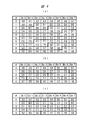
- FIG. 3 is an explanatory diagram showing an example of cumulative disparity control by the polarity control unit 206 of FIG.
- the disparity of the lower bit code is 0 and ⁇ 2
- the converted disparity of the upper bit code is 0 and ⁇ 4
- the previous cumulative disparity is 0, +2, +4, ⁇
- the code selection in case 2 and the total accumulated disparity in that case are shown in FIGS.
- the total accumulated disparity is the sum of the previous accumulated disparity and the converted disparity of the upper / lower bit code.
- the total disparity shown with an underline indicates a combination of codes that are not selected because the absolute value of the total disparity is large, and the disparity is the absolute value of the total disparity in the bold line frame.
- a combination of codes with small values is preferentially used.
- the disparity of the lower bit code is 0 and the disparity of the upper bit code is selected to be either +4 or ⁇ 4 in FIG.
- the absolute value of is 4. Therefore, either one can be selected, but by deciding which one to select in advance, the logic circuit can be rationalized and the fluctuation range of the total disparity value can be reduced. Further, the DC balance may be further improved by selecting +4 if it is ⁇ when looking at the history of the accumulated disparity before that, but not if it is +, and ⁇ 4 if it is +.
- the upper bit code selects 0 or +4, and when the previous cumulative disparity is 0 or negative, the upper bit code is the converted disparity. It is preferable to select 0 or +4 for the parity.
- the lower bit code takes a disparity 0 or -2 code when the upper bit code converted disparity is +4, and takes a disparity 0 or +2 code when the upper bit code converted disparity is -4.
- the converted disparity of the upper bit code When the converted disparity of the upper bit code is 0, it depends on the previous cumulative disparity, and when the previous cumulative disparity is 0 or -2, disparity 0 or +2, and when the previous cumulative disparity is +2 or +4, Select a disparity 0 or -2 code.
- the polarity control of the upper bits may be the same as TMDS for binary output or so-called 8B / 10B.
- the polarity control of the lower bits depend on the polarity control result of the upper bits, 4
- the accumulated disparity of the value output can be kept small and a good DC balance can be realized.
- the receiving unit 153 restores the signal received by the multi-value input unit 221 to lower bits and upper bits, and the serial-to-parallel conversion unit 222 and the first serial-to-parallel conversion unit, which become the second serial-to-parallel conversion unit, To the serial-parallel converter 232.
- the serial-parallel converters 222 and 232 convert the serial bit strings into 10-bit codes, respectively, and output them to the decoders 223 and 224, respectively.
- the error detection unit 227 detects an error such as no corresponding code or an error in the disparity value (when the code is different from the code selection technique described in FIG. 3), and the reliability of the transmission system is detected. Assess degree.
- the error detection unit 227 estimates 10-bit encoding when the decoded 8-bit valid data is input to the encoding units 204 and 214, and the result is the 10-bit code input to the decoding units 223 and 224. Different cases may be detected as transmission errors.
- the transmitting device If there are many errors and the reliability is low, it is transmitted to the transmitting device through the EDID storage unit 156, the CEC unit 159, etc., and the video format is changed to take measures such as changing the multilevel transmission to binary transmission or reducing the clock speed.
- the pseudorandom number generator 225 generates a pseudorandom number synchronized with the pseudorandom number generator 202 of the transmission unit 103.
- the descrambling units 224 and 234 scramble the 8-bit code output by the serial-parallel conversion units 222 and 232 and the 8-bit pseudorandom number generated by the pseudorandom number generator 225 and the exclusive OR for each bit. Is released.
- the scramble release unit 224 serves as a second scramble release unit, and the scramble release unit 234 serves as a first scramble release unit.
- the unscrambled upper bit group 8 bit code and lower bit group 8 bit are combined by a composite unit 226 which is a composite unit to obtain 8 bits of video data for 2 pixels.
- HDCP When the video signal is encrypted by HDCP, HDCP normally generates a 24-bit pseudo random number of 3 colors with 8 bits per pixel in synchronization with the same TMDS character clock as the pixel clock.
- the encryption unit 102 and the encryption / decryption unit 152 are preferably operated by a pixel clock corresponding to twice the TMDS character clock.
- the case of 8 bits per pixel has been described.
- the number of bits per pixel is expanded to 10 bits, 12 bits, or 16 bits to transmit a video signal with a smoother gradation. This is called a deep color mode in HDMI.
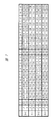
- FIG. 4 is an explanatory diagram showing an example of 10-bit deep color transmission timing in the transmission / reception system according to the second embodiment.
- FIG. 4 shows the 10-bit deep color transmission data described above in time series.
- 4A is an input of the selector 201
- FIG. 4B is an upper bit group output from the selector 201 to the scramble providing unit 213
- FIG. 4C is an output from the selector 201 to the scramble providing unit 203. Each lower bit group is shown.
- HDMI transmits, for example, three-color RGB (Red / Green / Blue) video signals as differential signals of 8 bits / character clock through independent TMDS lines.
- RGB Red / Green / Blue
- FIG. 4A among the 10-bit images A0 to A9 of the first pixel, 8 bits of the images A0 to A7 are transmitted in the clock 0 period, and the image is displayed at the first timing of the subsequent clock 1 period. A8 and A9 are transmitted.
- the selector 201 extracts the upper 5 bits from the 10-bit input data per pixel shown in FIG. 4A and rearranges them in units of 8 bits as shown in FIG. 4B. That is, the upper 5 bits A5 to A9 of the first pixel image and the upper 5 bits B5 to B7 of the second pixel image are transmitted in the clock 0 period.
- the remaining B8 and B9 in the upper 5 bits of the second pixel video, the upper 5 bits C5 to C9 of the third image video, and C0 among the upper 5 bits of the fourth pixel video are transmitted.
- the upper 5 bits of the video are assigned to an 8-bit transmission unit, and the upper 5 bits of the video for 8 pixels are transmitted in a 5-character clock period.
- the selector 201 takes out the lower 5 bits from the 10-bit input data per pixel shown in FIG. 4A and rearranges them in units of 8 bits as shown in FIG. 4C.
- the multi-value transmission is performed from the transmission unit 103 to the reception unit 153 after scrambling and encoding as in the first embodiment. Then, after decoding and descrambling, the signals shown in FIGS. 4B and 4C are reproduced and input to the composite unit 226.
- the composite unit 226 performs the reverse process of the rearrangement operation of the selector 201 to restore the 10-bit deep color video in FIG.
- multi-level transmission is not performed by dividing the upper 4 bits and the lower 4 bits of the 8-bit transmission unit into multi-level transmission, but by dividing the upper 5 bits and the lower 5 bits of a 10-bit video. Accordingly, when the error rate of the lower bit group is high, the influence on the video is limited to the lower bits of the video, and high-quality video transmission can be realized.
- the 10-bit deep color has been described as an example.
- 8 bits such as 12 bits and 16 bits, the same can be handled.
- the TMDS line of the HDMI cable 200 that connects the transmission unit 103 and the reception unit 153 shown in FIG. 1 is composed of three data lines and a clock line as described in the first embodiment. .
- FIG. 5 is an explanatory diagram showing an example of a transmission waveform from which a clock can be extracted according to the third embodiment.
- FIG. 5 shows an example of a waveform when the multilevel code has four levels.
- FIG. 6 is an explanatory diagram showing an example of bit arrangement in the transmission waveform shown in FIG.
- I indicates the bit string number in the word
- Ui indicates the i-th upper bit
- Di indicates the i-th lower bit.
- i is an integer of 0 or more.
- U0 and D0 are set to “0” and U1 and D1 are set to “1” to indicate the beginning of the word.
- A0 to A7, B0 to B7, C0 to C7, and D0 to D7 are 8-bit video data of the first pixel, the second pixel, the third pixel, and the fourth pixel, respectively.
- S0 to S3 are polarity codes of the subsequent bit string. If “0”, the subsequent 8-bit data is video data, and if “1”, the video data is inverted.
- the exclusive OR (ExOR) of the bits A4 to A7 and B4 to B7 and the polarity code S1 becomes the video data.
- S0 to S4 are determined by the polarity control unit 206 so that the absolute value of the total value of the accumulated disparity so far and the disparity of the subsequent bit string is minimized, and is encoded.
- the units 204 and 214 are controlled.
- the encoding units 204 and 214 can be realized by, for example, an exclusive OR circuit.
- the polarity code S1 of the upper bit may be determined first, and then the polarity code S0 of the lower bit may be determined.
- a combination that minimizes the accumulated disparity after the word transmission may be selected from the combinations of S1 and S3 by simply extending the word. If the cumulative disparity value after word transmission is determined from all combinations of the polarity control codes S0 to S3 in the word, the cumulative disparity value can be made smaller and the DC balance is improved. Thus, it is possible to realize a reliable video transmission with few errors.
- the word synchronization signal is always performed at the rising timing, but the falling timing may be used, or the rising and falling may be switched for each word.
- the rising and falling it is useful for grasping the characteristics of the transmission path, and there is an advantage that the reception error of the quaternary code can be suppressed low.
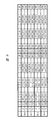
- FIG. 7 is an explanatory diagram showing an example of rearrangement of video data when a TMDS line and a clock line are combined and a video signal capable of clock extraction is transmitted simultaneously for 4 channels.
- a luminance color difference signal format is used, the luminance signal Y per pixel is 12 bits, and the color difference signals Cb and Cr are 10 bits each. It aims at assigning more bits to the luminance signal than the color difference signal to make the gradation display smoother.
- the first numbers 0 to 3 following the luminance signal Y and the color difference signals Cb and Cr indicate pixel numbers, and the second numbers 0 to B (in hexadecimal notation) indicate bit numbers.
- the upper bits Yj8 to YjB of the luminance signal of the jth pixel are transmitted with the upper bits of ch1, and the subsequent upper bits Yj6 and Yj7 are transmitted with the upper bits of ch3.
- j is an integer of 0 or more.
- the high-order bits Cbj6 to Cbj9 of the color difference signal of the j-th pixel are transmitted with the high-order bits of ch0, and the subsequent high-order bits Cbj5 are transmitted with the high-order bits of ch3.
- the upper bits Crj6 to Crj9 of the other color difference signal of the 0th pixel are transmitted as the upper bits of ch2, and the subsequent upper bits Crj5 are transmitted as the upper bits of ch3.
- the selector 201 rearranges the multi-valued transmission so that the high-order bits of the video signal are assigned to the high-order bits of the multi-value transmission, and the composite unit 226 restores it.
- the composite unit 226 restores it.
- ch. 3 is divided into luminance signals Yj0 to Yj3 and color difference signals Cbj0, Cbj1, Crj0, and Crj1, and if image quality is not an issue, the ch3 transmission is stopped to save energy, and each ch0 to Ch2 switches to 8-bit video. It may be rearranged so as to facilitate.
- the luminance signal is 12 bits.
- the most significant 2 bits may be assigned to the HDR (High Dynamic Range) control signal of the luminance color difference signal, and the luminance color difference signals Y, Cb, and Cr may be 10 bits each.
- the HDR control signal video transmission with a wide dynamic range can be realized by switching the setting of the maximum luminance and the minimum luminance of EOTF (Electro-Optical-Transfer Function). A plurality of types of EOTF may be switched.
- This HDR control signal may be prepared for each pixel, or the number of switching types may be increased in units of a plurality of pixels. If a 2-bit HDR control signal is prepared for each pixel, four types of EOTF can be switched. The HDR parameter with a large amount of information is transmitted as metadata transmitted during the blanking period of the video, etc., and by switching four types among them, finer control can be realized.
- the EMI noise may be reduced by reducing the amplitude of the word synchronization signal as (1, 0, 0, 1) or (0, 1, 1, 0). Further, by mixing the large amplitude and the small amplitude synchronization, for example, (0, 0, 1, 1) (0, 1, 1, 0) (1, 1, 0, 0) (1, 0, It may be switched to 0,1).
- the polarity of the data string that continues with the type of word synchronization may be indicated, and the polarity bit may also be used to increase the encoding efficiency.
- FIG. 8 is an explanatory diagram showing an example of transmission timing of video data of the three primary color video signals RGB according to the fourth embodiment.
- FIG. 8 shows an example in which the primary color signal G is 10 bits per pixel, and the primary color signals R and B are 9 bits each for a total of 28 bits.
- the upper bits Gj6 to Gj9 of the primary color signal G of the jth pixel are the upper bits of ch1
- the upper bits Bj5 to Gj8 of the primary color signal B are the upper bits of ch0
- the upper bits Rj5 to Rj8 of the primary color signal R are the upper bits of ch2. It is transmitted with. Further, redundant codes Ej1 to Ej3 for error correction are respectively transmitted with the upper bits of ch3.
- one word excluding the synchronization bit is divided into the first half and the second half, and the unit is 2 pixels including the polarity control bit.
- the upper 4 bits of the primary color signal RGB of the 0th pixel and the 1st pixel are 24 bits in total and the 3 bits of ch0 to 2 polarity codes S01, S02, S03 are 27 bits in total, for error correction of 8 bits. Redundant codes E00 to E03 and E10 to E13 are assigned.
- the polarity code S31 of ch3 is not determined until the redundant codes E00 to E03 and E10 to E13 are determined, it is not included in the total code length of the redundant code calculation.
- the polarity code S31 is incorrect, it is recognized as an uncorrectable error of 2 bits or more.
- the decoding unit 223 may invert the polarity code S31 and decode the redundant codes E00 to E03 and E10 to E13 again.
- the decoding when the polarity code S31 is both “0” and “1” may be calculated at the same time, and the decoding result with fewer error bits may be employed.
- the redundant code length for 1-bit error correction may be 6 bits. Therefore, 2 bits out of 8 bits of the redundant code are allocated to the primary color signals R and B, and the effective code length 29 The gradation may be enhanced as a bit.
- the primary color signal R or B of 3 pixels may be converted to 10 bits, or may be assigned to the primary color signal R of the first pixel and the primary color signal B of the second pixel.
- the HDR control signal described in the third embodiment may be used.
- the redundant code length may be 6 bits
- the coding of ch3 U2 to U10 (assigned to S21, E00 to E03, and E10 to E13 in FIG. 8) is changed to an encoding method that does not require transmission of polarity bits. It may be replaced.
- 9 bits U2 to U10 are divided into 3 groups each having 3 bits, and each group allocates 2 bits of necessary redundant bits.
- the lower bits Gj2 to Gj5 of the primary color signal G of the jth pixel are transmitted by the lower bits of ch1, and the lower bits Gj0 and Gj1 are transmitted by the lower bits of ch3.
- the lower bits Bj1 to Gj4 of the primary color signal B are transmitted with the lower bits of ch0, and the lower bit Bj0 of the primary color signal B is transmitted with the lower bits of ch3.
- the lower bits Rj1 to Rj4 of the primary color signal R are transmitted as the lower bits of ch2, and the lower bit Rj0 of the primary color signal R is transmitted as the lower bits of ch3.
- the lower bit of the primary color signal has less influence on the image quality than the upper bit, so instead of not using an error correction code, priority is given to smooth gradation display by increasing the number of gradations.
- G is 10 bits
- G and B are 9 bits each.
- the error correction described above may be applied to the lower bits.
- the total code length is 71 bits in total of U2 to U10 of ch0 to 3 and D2 to 10, excluding U2 to which the polarity bit S31 of ch3 is assigned.
- the redundant code is 8 bits (E00 to E04 and E10 to E14), and the effective bit is 63 bits (total primary color signal RGB for 2 pixels is 56 bits and polarity bit is 7 bits), and 1-bit error correction is possible. Redundant codes are easy to ensure reliability when placed in higher bits with relatively high transmission reliability.
- FIG. 9 is an explanatory diagram showing an example of transmission timing of video data of three primary color signals according to the fifth embodiment.
- FIG. 9 shows an example in which three primary color signals of 12 bits for each color and 36 bits in total are transmitted.
- Each channel transmits primary color signals R, G, and B in order for each pixel.
- ch0 transmits 0th and 4th pixels
- ch1 transmits 1st and 5th pixels
- ch2 transmits 2nd and 6th pixels
- ch3 transmits 3rd and 7th pixels.
- HDMI uses 10-bit transmission for each channel as a unit, and performs encoding by adding redundant bits to 8-bit RGB primary color signals in ch0 to ch2. Therefore, in the case of 40-bit transmission unit, the HDMI is 24 bits ⁇ 4 pixels transmission, whereas in the fifth embodiment, the transmission is 36 bits ⁇ 8 pixels. As described above, since 3 times as much video data can be transmitted efficiently, high-resolution video transmission with high resolution and high dynamic range can be realized.
- the video data for one pixel is transmitted in half the HDMI ratio, so there is an advantage that the timing between the video pixel clock and the transmission clock can be easily taken.
- a twisted pair line composed of a Utility line and an HPD line of the HDMI cable 200 is prepared for Ethernet bidirectional transmission.
- FIG. 10 is an explanatory diagram showing an example of transmission timing of video data of three primary color signals according to the sixth embodiment.
- FIG. 10 the difference from FIG. 9 of the fifth embodiment is that a channel 4 is added, 40B / 36B conversion is set to 100B / 96 conversion, each primary color 12-bit transmission is 8-bit transmission, and the transmission system is focused on resolution. It is a point.
- the primary color signals Rj0 to Rj7, Gj0 to Gj7, and Bj0 to Bj7 are collectively described as RGBj.
- j is an integer greater than or equal to 0 and expressed in two digits. Since the basic operation is the same, description of the operation is omitted.
- FIG. 11 is an explanatory diagram showing an example of transmission timing of video data of three primary color signals according to the seventh embodiment.
- each bit transmission 4 bits can be transmitted by 2 bits per channel, and 10 channels can be transmitted because there are 5 channels. By assigning these 10 bits to 10 bits of each primary color signal, transmission can be performed efficiently.
- the high-order bits of each primary color signal are assigned to the high-order bits of each channel to ensure reliability.
- channel ch4 using a twisted pair line for Ethernet bidirectional transmission may be inferior in high-speed transmission compared to channels ch0 to ch3 using other TMDS lines, relatively low-order bit data is assigned to ch4. Therefore, even if the error rate of the transmission path increases, the influence on the image quality can be reduced.
- Embodiments 1 to 7 improve the transmission speed by multi-value transmission controlled by DC balance, suppress the influence on image quality, and support a high dynamic range. Image quality transmission can be realized.
- a part of the configuration of one embodiment can be replaced with the configuration of another embodiment, and the configuration of another embodiment can be added to the configuration of one embodiment. .
Landscapes
- Engineering & Computer Science (AREA)
- Physics & Mathematics (AREA)
- Computer Hardware Design (AREA)
- General Physics & Mathematics (AREA)
- Theoretical Computer Science (AREA)
- Spectroscopy & Molecular Physics (AREA)
- Computer Networks & Wireless Communication (AREA)
- Signal Processing (AREA)
- Two-Way Televisions, Distribution Of Moving Picture Or The Like (AREA)
Abstract
L'invention concerne un système d'émission et de réception comportant un dispositif 10 d'émission et un dispositif 15 de réception. Dans le dispositif 10 d'émission, une unité 204 de codage détermine des données de code à partir de la disparité cumulative de données de code codées par une unité 214 de codage, de la disparité cumulative de données de code codées par l'unité 204 de codage, et de la disparité de données de code déterminée par l'unité 214 de codage, et délivre les données de code déterminées. Dans le dispositif 15 de réception, une unité 226 de combinaison combine des données désembrouillées par une unité de désembrouillage 234 et une unité 224 de désembrouillage, trie les données combinées dans des unités d'entrée à manipuler par une unité 152 de déchiffrement, et délivre les données triées à l'unité 152 de déchiffrement.
Priority Applications (1)
| Application Number | Priority Date | Filing Date | Title |
|---|---|---|---|
| PCT/JP2015/053870 WO2016129088A1 (fr) | 2015-02-12 | 2015-02-12 | Dispositif d'émission, dispositif de réception, et système d'émission et de réception |
Applications Claiming Priority (1)
| Application Number | Priority Date | Filing Date | Title |
|---|---|---|---|
| PCT/JP2015/053870 WO2016129088A1 (fr) | 2015-02-12 | 2015-02-12 | Dispositif d'émission, dispositif de réception, et système d'émission et de réception |
Publications (1)
| Publication Number | Publication Date |
|---|---|
| WO2016129088A1 true WO2016129088A1 (fr) | 2016-08-18 |
Family
ID=56614580
Family Applications (1)
| Application Number | Title | Priority Date | Filing Date |
|---|---|---|---|
| PCT/JP2015/053870 Ceased WO2016129088A1 (fr) | 2015-02-12 | 2015-02-12 | Dispositif d'émission, dispositif de réception, et système d'émission et de réception |
Country Status (1)
| Country | Link |
|---|---|
| WO (1) | WO2016129088A1 (fr) |
Citations (6)
| Publication number | Priority date | Publication date | Assignee | Title |
|---|---|---|---|---|
| JPS5910056A (ja) * | 1982-06-30 | 1984-01-19 | インタ−ナシヨナル ビジネス マシ−ンズ コ−ポレ−シヨン | コ−ド生成方法 |
| JPH0275224A (ja) * | 1988-09-12 | 1990-03-14 | Sony Corp | データ伝送装置 |
| JP2001333217A (ja) * | 2000-05-18 | 2001-11-30 | Gigalink Co Ltd | 電話線を通じて音声とデータとを送受信するデータ送受信器 |
| JP2008526170A (ja) * | 2004-12-29 | 2008-07-17 | エニグマ セミコンダクター,インコーポレイテッド | 16b/10s符号化装置および方法 |
| JP2010213263A (ja) * | 2009-02-10 | 2010-09-24 | Panasonic Corp | 送信装置 |
| WO2013061520A1 (fr) * | 2011-10-26 | 2013-05-02 | パナソニック株式会社 | Dispositif de modulation en amplitude multiniveau, dispositif de démodulation en amplitude multiniveau, système de transmission utilisant de tels dispositifs, procédé de modulation en amplitude multiniveau et procédé de démodulation en amplitude multiniveau |
-
2015
- 2015-02-12 WO PCT/JP2015/053870 patent/WO2016129088A1/fr not_active Ceased
Patent Citations (6)
| Publication number | Priority date | Publication date | Assignee | Title |
|---|---|---|---|---|
| JPS5910056A (ja) * | 1982-06-30 | 1984-01-19 | インタ−ナシヨナル ビジネス マシ−ンズ コ−ポレ−シヨン | コ−ド生成方法 |
| JPH0275224A (ja) * | 1988-09-12 | 1990-03-14 | Sony Corp | データ伝送装置 |
| JP2001333217A (ja) * | 2000-05-18 | 2001-11-30 | Gigalink Co Ltd | 電話線を通じて音声とデータとを送受信するデータ送受信器 |
| JP2008526170A (ja) * | 2004-12-29 | 2008-07-17 | エニグマ セミコンダクター,インコーポレイテッド | 16b/10s符号化装置および方法 |
| JP2010213263A (ja) * | 2009-02-10 | 2010-09-24 | Panasonic Corp | 送信装置 |
| WO2013061520A1 (fr) * | 2011-10-26 | 2013-05-02 | パナソニック株式会社 | Dispositif de modulation en amplitude multiniveau, dispositif de démodulation en amplitude multiniveau, système de transmission utilisant de tels dispositifs, procédé de modulation en amplitude multiniveau et procédé de démodulation en amplitude multiniveau |
Similar Documents
| Publication | Publication Date | Title |
|---|---|---|
| JP4229836B2 (ja) | 一群の受信ワードの各ワードを単一送信ワードにマッピングすることで連続リンク送信上のシンボル間干渉効果を低減させる方法および装置。 | |
| KR100552833B1 (ko) | 시리얼 링크를 통한 전송시 심벌 간의 간섭 효과를 감소시키기 위한 인코딩 방법 및 시스템 | |
| US8780932B2 (en) | Video signal transmission device, video signal reception device, and video signal transmission system | |
| US10680858B2 (en) | Methods and apparatus for the intelligent scrambling of control symbols | |
| US9210010B2 (en) | Methods and apparatus for scrambling symbols over multi-lane serial interfaces | |
| US8810560B2 (en) | Methods and apparatus for scrambler synchronization | |
| KR100810815B1 (ko) | 등화 신호들 중 하나로부터 생성되는 제어 신호에 응답하여다수의 신호를 적응성 등화하기 위한 방법 및 회로 | |
| US20080266146A1 (en) | Method and system for generating high definition multimedia interface (hdmi) codewords using a tmds encoder/decoder | |
| US7146051B2 (en) | Apparatus for and method of transmitting optical signal of graphic signal | |
| TWI565254B (zh) | 於多媒體介面中減少射頻干擾 | |
| US9258603B2 (en) | Method and system for achieving higher video throughput and/or quality | |
| US9191700B2 (en) | Encoding guard band data for transmission via a communications interface utilizing transition-minimized differential signaling (TMDS) coding | |
| TW201801534A (zh) | 影像信號發送裝置、影像信號接收裝置、及影像信號傳送系統 | |
| WO2016129088A1 (fr) | Dispositif d'émission, dispositif de réception, et système d'émission et de réception | |
| JP3851904B2 (ja) | 一群の受信ワードの各ワードを単一送信ワードにマッピングすることで連続リンク送信上のシンボル間干渉効果を低減させる方法および装置。 | |
| JPWO2017085969A1 (ja) | フレーム生成装置、フレーム生成方法、画像合成装置、画像合成方法、信号生成装置、信号生成方法、画像伝送システムおよび画像伝送方法 |
Legal Events
| Date | Code | Title | Description |
|---|---|---|---|
| 121 | Ep: the epo has been informed by wipo that ep was designated in this application |
Ref document number: 15881963 Country of ref document: EP Kind code of ref document: A1 |
|
| NENP | Non-entry into the national phase |
Ref country code: DE |
|
| 122 | Ep: pct application non-entry in european phase |
Ref document number: 15881963 Country of ref document: EP Kind code of ref document: A1 |
|
| NENP | Non-entry into the national phase |
Ref country code: JP |