WO2016129202A1 - Haut-parleur piézoélectrique - Google Patents
Haut-parleur piézoélectrique Download PDFInfo
- Publication number
- WO2016129202A1 WO2016129202A1 PCT/JP2016/000049 JP2016000049W WO2016129202A1 WO 2016129202 A1 WO2016129202 A1 WO 2016129202A1 JP 2016000049 W JP2016000049 W JP 2016000049W WO 2016129202 A1 WO2016129202 A1 WO 2016129202A1
- Authority
- WO
- WIPO (PCT)
- Prior art keywords
- piezoelectric
- piezoelectric element
- metal
- plate
- speaker according
- Prior art date
- Legal status (The legal status is an assumption and is not a legal conclusion. Google has not performed a legal analysis and makes no representation as to the accuracy of the status listed.)
- Ceased
Links
Images


Classifications
-
- H—ELECTRICITY
- H04—ELECTRIC COMMUNICATION TECHNIQUE
- H04R—LOUDSPEAKERS, MICROPHONES, GRAMOPHONE PICK-UPS OR LIKE ACOUSTIC ELECTROMECHANICAL TRANSDUCERS; ELECTRIC HEARING AIDS; PUBLIC ADDRESS SYSTEMS
- H04R1/00—Details of transducers, loudspeakers or microphones
- H04R1/20—Arrangements for obtaining desired frequency or directional characteristics
- H04R1/22—Arrangements for obtaining desired frequency or directional characteristics for obtaining desired frequency characteristic only
- H04R1/30—Combinations of transducers with horns, e.g. with mechanical matching means, i.e. front-loaded horns
-
- H—ELECTRICITY
- H04—ELECTRIC COMMUNICATION TECHNIQUE
- H04R—LOUDSPEAKERS, MICROPHONES, GRAMOPHONE PICK-UPS OR LIKE ACOUSTIC ELECTROMECHANICAL TRANSDUCERS; ELECTRIC HEARING AIDS; PUBLIC ADDRESS SYSTEMS
- H04R17/00—Piezoelectric transducers; Electrostrictive transducers
-
- H—ELECTRICITY
- H04—ELECTRIC COMMUNICATION TECHNIQUE
- H04R—LOUDSPEAKERS, MICROPHONES, GRAMOPHONE PICK-UPS OR LIKE ACOUSTIC ELECTROMECHANICAL TRANSDUCERS; ELECTRIC HEARING AIDS; PUBLIC ADDRESS SYSTEMS
- H04R23/00—Transducers other than those covered by groups H04R9/00 - H04R21/00
- H04R23/02—Transducers using more than one principle simultaneously
-
- H—ELECTRICITY
- H04—ELECTRIC COMMUNICATION TECHNIQUE
- H04R—LOUDSPEAKERS, MICROPHONES, GRAMOPHONE PICK-UPS OR LIKE ACOUSTIC ELECTROMECHANICAL TRANSDUCERS; ELECTRIC HEARING AIDS; PUBLIC ADDRESS SYSTEMS
- H04R7/00—Diaphragms for electromechanical transducers; Cones
- H04R7/02—Diaphragms for electromechanical transducers; Cones characterised by the construction
- H04R7/04—Plane diaphragms
Definitions
- the present invention relates to a piezoelectric speaker.
- piezoelectric speaker that includes a piezoelectric element that receives an electric signal and vibrates, and a vibrating body to which the piezoelectric element is bonded via a bonding material.
- Patent Document 1 discloses a piezoelectric speaker in which the bonding material has a protruding portion that protrudes from the outer edge of the piezoelectric element when the vibrating body is viewed in plan. At least a part of the protruding portion has a wavy shape. Thereby, the frequency characteristic of the sound pressure can be flattened.
- the present invention provides a piezoelectric speaker having good sound pressure frequency characteristics in a high frequency region.
- the piezoelectric speaker according to the present invention is Including a piezoelectric element, and a metal vibration part obtained by bonding the piezoelectric element via an adhesive part,
- the piezoelectric element is a substantially rectangular plate
- the metal vibrating portion includes a substantially rectangular plate-like portion that is vibrated by the piezoelectric element,
- the frequency of the natural vibration mode of the piezoelectric element is set different from the frequency of the natural vibration mode of the metal vibration part.
- the adhesive portion may be an elastic body.
- the mechanical quality factor Qm of the vibrating body in which the piezoelectric element and the bonding portion are integrated may satisfy Qm ⁇ 5.0.
- it may further include a case having a sound emitting hole provided with the metal vibrating portion, and the sound emitting hole may have a horn shape.
- the rectangular plate-like portion may have a frequency adjustment hole.
- a case may be further included, and the metal vibrating portion may be bonded to the case via an elastic body.
- the plurality of piezoelectric elements may be bonded to the metal vibrating portion via the bonding portion.
- the frequencies of the natural vibration modes of the plurality of piezoelectric elements may be different.
- the metal vibration part may have a single metal plate, and the plurality of piezoelectric elements may be bonded to the metal plate via the bonding part.
- the plurality of piezoelectric elements may be attached to the same surface of the metal plate. You may further provide the case and the electromagnetic speaker arrange
- the piezoelectric element may be disposed inside the case.
- the mounting surface of the electromagnetic speaker and the mounting surface of the piezoelectric element may be the same surface of the case.
- the piezoelectric element may be disposed outside the case, and the mounting surface of the electromagnetic speaker and the mounting surface of the piezoelectric element may be opposing surfaces of the case.
- the metal vibration part may be a side plate or a back plate of the case.
- a cover that covers the opening of the case may be further provided, and the metal vibrating portion may be fixed to the case or the cover via an elastic member.
- the metal vibrating portion may include a metal plate having a thickness of 10 to 300 ⁇ m.
- a piezoelectric speaker includes a front plate having a sound emitting hole, a back plate facing the front plate, and a side plate between the front plate and the back plate. And an electromagnetic speaker provided inside the casing, and a piezoelectric element attached to the casing.
- the piezoelectric element may be fixed to the housing via an adhesive portion, and the adhesive portion may be an elastic body.
- the piezoelectric element may be disposed inside the housing.
- the mounting surface of the electromagnetic speaker and the mounting surface of the piezoelectric element may be the same surface of the housing.
- the piezoelectric element may be disposed outside the housing, and the mounting surface of the electromagnetic speaker and the mounting surface of the piezoelectric element may be opposing surfaces of the housing.
- the mounting surface of the piezoelectric element may be a metal plate.
- the metal plate may be fixed to the side plate, the front plate, or the back plate via an elastic member.
- the metal plate may have a thickness of 10 to 300 ⁇ m.
- the side plate, the front plate, or the back plate is a mounting surface of the piezoelectric element, and may include a metal material and a resin material.
- a piezoelectric speaker having good sound pressure frequency characteristics in a high frequency region can be provided.
- FIG. 1 is a perspective view of a piezoelectric speaker according to a first embodiment.
- 1 is a cross-sectional view of a piezoelectric speaker according to a first embodiment.
- FIG. 3 is a bottom view of the main part of the piezoelectric speaker according to the first embodiment. It is a graph which shows the sound pressure with respect to a frequency. It is a graph which shows the sound pressure with respect to a frequency.
- FIG. 6 is a bottom view of a main part of a piezoelectric speaker according to a second embodiment.
- FIG. 10 is a cross-sectional view of Modification 1 of the main part of the piezoelectric speaker according to the second embodiment.
- FIG. 10 is a cross-sectional view of Modification 1 of the main part of the piezoelectric speaker according to the second embodiment.
- FIG. 10 is a cross-sectional view of Modification 1 of the main part of the piezoelectric speaker according to the second embodiment.
- FIG. 10 is a cross-sectional view of Modification 1 of the main part of the piezoelectric speaker according to the second embodiment.
- FIG. 10 is a cross-sectional view of Modification 2 of the main part of the piezoelectric speaker according to the second embodiment.
- FIG. 10 is a cross-sectional view of Modification 2 of the main part of the piezoelectric speaker according to the second embodiment.
- FIG. 10 is a cross-sectional view of Modification 2 of the main part of the piezoelectric speaker according to the second embodiment.
- FIG. 10 is a cross-sectional view of Modification 2 of the main part of the piezoelectric speaker according to the second embodiment.
- FIG. 10 is a cross-sectional view of Modification 2 of the main part of the piezoelectric speaker according to the second embodiment.
- FIG. 10 is a cross-sectional view of Modification 3 of the main part of the piezoelectric speaker according to the second embodiment.
- FIG. 10 is a cross-sectional view of Modification 3 of the main part of the piezoelectric speaker according to the second embodiment.
- FIG. 10 is a cross-sectional view of Modification 3 of the main part of the piezoelectric speaker according to the second embodiment.
- FIG. 10 is a cross-sectional view of Modification 3 of the main part of the piezoelectric speaker according to the second embodiment.
- FIG. 10 is a cross-sectional view of Modification 4 of the main part of the piezoelectric speaker according to the second embodiment.
- FIG. 10 is a cross-sectional view of Modification 4 of the main part of the piezoelectric speaker according to the second embodiment.
- FIG. 10 is a cross-sectional view of Modification 4 of the main part of the piezoelectric speaker according to the second embodiment.
- FIG. 10 is a cross-sectional view of Modification 4 of the main part of the piezoelectric speaker according to the second embodiment.
- FIG. 10 is a cross-sectional view of Modification 5 of the main part of the piezoelectric speaker according to the second embodiment.
- FIG. 10 is a cross-sectional view of Modification 5 of the main part of the piezoelectric speaker according to the second embodiment.
- FIG. 5 is an exploded perspective view of a piezoelectric speaker according to a third embodiment.
- FIG. 10 is a cross-sectional view of Modification 4 of the main part of the piezoelectric speaker according to the second embodiment.
- FIG. 10 is a cross-sectional view of Modification 4 of the main part of the piezo
- FIG. 6 is an exploded perspective view of a modification of the piezoelectric speaker according to the third embodiment.
- FIG. 6 is an exploded perspective view of a modification of the piezoelectric speaker according to the third embodiment.
- 3 is a graph showing sound pressure with respect to frequency of an example of the piezoelectric speaker according to the first exemplary embodiment; It is a graph which shows the sound pressure with respect to the frequency of a related speaker. It is a bottom view of a related piezoelectric speaker. It is a graph which shows the sound pressure with respect to the frequency of a related piezoelectric speaker.
- 6 is a cross-sectional view of a piezoelectric speaker according to a fourth embodiment.
- FIG. 6 is a bottom view of a main part of a piezoelectric speaker according to a fourth embodiment. 6 is a graph showing sound pressure with respect to frequency of a piezoelectric speaker according to a fourth exemplary embodiment.
- FIG. 10 is a perspective view illustrating a configuration of a piezoelectric speaker according to a fifth embodiment.
- FIG. 10 is a cross-sectional view of a main part of a piezoelectric speaker according to a fifth embodiment.
- 6 is a graph showing sound pressure with respect to frequency of a piezoelectric speaker according to a fifth exemplary embodiment.
- FIG. 10 is a cross-sectional view of a main part of a piezoelectric speaker according to a sixth modification of the fifth embodiment.
- FIG. 10 is a cross-sectional view of a main part of a piezoelectric speaker according to a sixth modification of the fifth embodiment.
- FIG. 10 is a cross-sectional view of a main part of a piezoelectric speaker according to Modification 7 of Embodiment 5.
- FIG. 10 is a cross-sectional view of a main part of a piezoelectric speaker according to Modification 8 of Embodiment 5.
- FIG. 1 is a perspective view of the piezoelectric speaker according to the first embodiment.
- FIG. 2 is a cross-sectional view of the piezoelectric speaker according to the first embodiment.
- the piezoelectric speaker 100 includes a cover 5, a case 6, and a piezoelectric vibration unit 7.
- the cover 5 is a plate-like body having a sound emitting hole 5a in the center thereof.
- the sound emission hole 5 a passes through the cover 5, and the cross-sectional shape of the sound emission hole 5 a becomes larger toward the outside of the piezoelectric speaker 100.
- the sound emission hole 5a has, for example, a horn shape.
- the case 6 is a rectangular parallelepiped housing having an opening 6a on one surface.
- the case 6 may be a frame-like body, and the frame shape thereof is a rectangular shape, for example, a substantially rectangular shape, a substantially rectangular shape, a substantially square shape, or a substantially trapezoidal shape.
- the opening 6 a is closed by the cover 5.
- the case 6 to which the cover 5 is attached has a width Lx, a depth Ly, and a height Lz.
- the width Lx is, for example, 10 to 20 mm
- the depth Ly is, for example, 5 to 10 mm
- the height Lz is, for example, 2 to 10 mm.
- the piezoelectric vibration unit 7 is bonded to the inner main surface of the cover 5 via the bonding portion 4. Specifically, the piezoelectric vibration unit 7 is bonded to the inner main surface of the cover 5 so as to close the sound emitting hole 5a.
- the adhesive portion 4 may be a viscoelastic body, a pressure-sensitive adhesive body, or a plate-like body or a belt-like body having adhesiveness on both main surfaces while having a predetermined elastic coefficient.
- the bonding portion 4 is preferably an elastic body. Examples of the bonding portion 4 include a plate-like body formed using a double-sided tape, a synthetic resin such as a silicone resin, an epoxy resin, or the like.
- the bonding portion 4 is preferably made of a material having mechanical properties such that the vibration of the piezoelectric vibration unit 7 maintains a necessary magnitude as a piezoelectric speaker.
- the adhesive portion 4 may be a frame-like body that is not exposed from the sound emitting hole 5a.
- the adhesion part 4 is arrange
- the bonding portion 4 has a predetermined elastic coefficient because an apparent mechanical quality factor Qm21 (described later) of the metal diaphragm 2 can be reduced.
- the piezoelectric vibration unit 7 includes a piezoelectric element 1, a metal vibration plate 2, and an adhesive portion 3.
- the piezoelectric element 1 is bonded to the metal diaphragm 2 through the bonding portion 3.
- the piezoelectric element 1 is a vibrator including a substantially rectangular plate made of a single ceramic plate.
- the piezoelectric element 1 may be a laminated type, a bimorph type, or a unimorph type.
- the piezoelectric element 1 is electrically connected to an amplifier (not shown) or the like, and vibrates when supplied with an electric signal for reproducing sound.
- the metal diaphragm 2 is a substantially rectangular plate (which may be referred to as a rectangular plate-like portion) having a larger area than the piezoelectric element 1.
- the metal diaphragm 2 is made of, for example, steel or copper alloy. Examples of the steel and copper alloy include stainless steel, brass, phosphor bronze and the like. The metal diaphragm 2 vibrates when the piezoelectric element 1 vibrates.
- the bonding part 3 is made of the same type of material as the bonding part 4.
- the metal diaphragm 2 has a thickness of 0.5 to 1.5 mm, for example.
- the size, shape, material, and the like of the metal diaphragm 2 are determined so that the natural vibration mode of the metal diaphragm 2 and the natural vibration mode of the piezoelectric element 1 are set to different frequencies. In other words, either the natural vibration mode frequency (resonance frequency) of the metal diaphragm 2 or the natural vibration mode frequency of the piezoelectric element 1 is high.
- the area Ap of the piezoelectric element 1 and the area Am of the metal diaphragm 2 and the relational expression can be obtained by using the following mathematical formula 1.
- the natural vibration mode of the metal diaphragm 2 and the natural vibration mode of the piezoelectric element 1 are more reliably set to different frequencies.
- the natural vibration mode of the metal diaphragm 2 is 10 to 20 kHz
- the natural vibration mode of the piezoelectric element 1 is about 30 kHz, which are set to different frequencies.
- the amplitude when the piezoelectric vibration unit 7 vibrates the metal diaphragm 2 is the metal diaphragm 2.
- the amplitude corresponding to the elastic coefficient of the piezoelectric element 1 are almost the same, or the amplitude corresponding to the elastic coefficient of the metal diaphragm 2 and the elastic coefficient of the piezoelectric element 1 are rarely exceeded. Further, even if the piezoelectric vibration unit 7 vibrates the metal diaphragm 2 to near the elastic limit of the metal diaphragm 2 and the piezoelectric element 1, the total harmonic distortion is not easily increased, and an unpleasant sound is not easily generated.
- the relational expression between the sound pressure SP1 and the total harmonic distortion THD1 is obtained by using the following Expression 2.
- SN1 SP1-THD1 (Formula 2)
- the SN ratio SN1 at 40 kHz is obtained using Equation 2 and is about 60 dBsql.
- the rigidity k2 of the metal diaphragm 2 is preferably 5 to 30, and the thickness t2 [mm] of the metal diaphragm 2 is 0.05 to 0.3. Good.
- the metal diaphragm 2 has a unique mechanical quality factor Qm20. Since the metal diaphragm 2 is bonded to the cover 5 via the bonding portion 4, the apparent mechanical quality factor Qm21 of the metal diaphragm 2 is used. Is lower than its inherent mechanical quality factor Qm20.
- the apparent mechanical quality factor Qm21 of the metal diaphragm 2 may be referred to as a mechanical quality factor Qm21 of a vibrating body in which the metal diaphragm 2 and the bonding portion 4 are integrated.
- the material and shape of the piezoelectric element 1, the metal diaphragm 2, and the bonding portion 3 may be set so that the apparent mechanical quality factor Qm 21 of the metal diaphragm 2 satisfies the following Equation 3.
- Qm21 ⁇ 5.0 (Formula 3)
- the sound pressure characteristic curve is flattened, which is preferable.
- the material and shape of the piezoelectric element 1, the metal diaphragm 2 and the bonding portion 3 are set so that the apparent mechanical quality factor Qm21 of the metal diaphragm 2 satisfies Formula 3 and Formula 4 below. Good.
- Qm21 ⁇ 0.5 (Formula 4)
- the piezoelectric element 1 is bonded to the metal diaphragm 2 via the bonding portion 3, the frequency band is widened.
- the rigidity k2 of the metal diaphragm 2 is preferably 5 to 20, for example, a plate made of brass or phosphor bronze.
- the sound pressure characteristic is flat over a wide frequency band. Sound can be played with a curve.
- a sound pressure characteristic curve of an example of the piezoelectric speaker 100 was measured, and this sound pressure characteristic curve is shown in FIG.
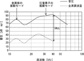
- Electromagnetic speaker By the way, as shown in FIG. 14, by using an example of an electromagnetic speaker that vibrates a diaphragm by supplying an electric signal to a voice coil and generating a magnetic moment, sound pressure and total harmonic distortion with respect to frequency are used.
- the SN ratio SN2 of this example is about 50 kHz, which is smaller than the SN ratio SN1 of the example of the piezoelectric speaker 100.
- An electromagnetic speaker reproduces sound having a high frequency of 20 kHz or higher using a voice coil. Then, the electric power given by the impedance increase at a high frequency is converted into heat rather than an audio signal. Therefore, it is considered that it is difficult for the electromagnetic speaker to achieve a high sound pressure and a high SN ratio compared to the piezoelectric speaker 100.
- the piezoelectric vibration unit 907 includes a piezoelectric element 901 and a metal vibration plate 902.
- the piezoelectric element 901 has the same configuration as the piezoelectric element 1 (see FIG. 2) except that it is a disc-shaped body. Except for the metal diaphragm 902 and the disc-like body, it has the same configuration as the metal diaphragm 2 (see FIG. 2).
- a piezoelectric speaker 900 (not shown) is formed by arranging the piezoelectric vibration unit 907 inside the cover 905 (not shown) and the case 6 (see FIG. 2).
- the cover 95 has the same configuration as the cover 5 except that the cover 95 has a sound emitting hole having a circular cross section.
- a piezoelectric element having a diameter of 20 mm and a thickness of 0.1 mm was used as the piezoelectric element 901, and a metal diaphragm made of stainless steel having a diameter of 25 mm and a thickness of 0.1 mm was used as the metal diaphragm 902.
- the mechanical quality factor Qm91 of the resonance frequency was 10 or more.
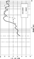
- the sound pressure characteristic curve shown in FIG. 16 has fewer flat parts, that is, more parts with undulations than the sound pressure curve shown in FIG. That is, it is difficult for the piezoelectric speaker 900 to obtain a flat sound pressure characteristic curve as compared with the piezoelectric speaker 100.
- the metal vibration part having a rectangular shape has many natural vibration modes that differ depending on the direction of the principal surface thereof, as compared with the metal vibration part having a circular shape.
- the direction of the main surface of the metal vibrating part having a rectangular shape includes, for example, a Y direction and an X direction as shown in FIG. Therefore, the mechanical quality factor Qm is low.
- the frequency can be easily adjusted by adjusting the sizes of the metal vibrating portion and the piezoelectric element.
- the piezoelectric speaker according to the first embodiment sound can be reproduced with good sound pressure characteristics in a high frequency region.
- a high frequency range for example, 20 kHz to 70 kHz
- the reproduced sound has a high sound pressure and a high S / N ratio.
- the sound pressure characteristic curve is flat and the frequency band is wide.
- FIG. A piezoelectric speaker according to the second embodiment will be described with reference to FIG.
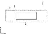
- FIG. 6 is a bottom view of the main part of the piezoelectric speaker according to the second embodiment.
- the description of the same configuration as the piezoelectric speaker according to the first embodiment will be omitted as appropriate, and a different configuration will be described.
- the piezoelectric speaker 200 (not shown) has the same configuration as the piezoelectric speaker 100 except for the piezoelectric vibration unit 7.
- the piezoelectric speaker 200 includes a piezoelectric vibration unit 207.
- the piezoelectric vibration unit 207 has the same configuration as the piezoelectric vibration unit 7 except for the metal vibration plate 2.
- the piezoelectric vibration unit 207 includes a metal vibration plate 22.
- the metal diaphragm 22 has the same configuration as the metal diaphragm 2 except that it has frequency adjustment holes 22b in the vicinity of the four corners. The effective length of the metal diaphragm 22 and the width of the metal diaphragm 22 can be adjusted by changing the number and size of the frequency adjustment holes 22b. Thereby, the frequency can be easily adjusted.
- the frequency adjusting method by changing the number and size of the frequency adjusting holes 22b described above is easier to vibrate the metal diaphragm than the frequency adjusting method of adjusting the frequency by providing an additional member on the metal diaphragm. Further, according to the frequency adjusting method by changing the number and size of the frequency adjusting holes 22b described above, even if the piezoelectric speaker 200 is superposed on an electromagnetic speaker, in particular, its diaphragm, the piezoelectric speaker 200 generates almost no sound reproduced by the electromagnetic speaker. Do not block. Further, the frequency adjusting hole 22b is formed by using etching or pressing. Therefore, the frequency adjusting method based on the number and size of the frequency adjusting holes 22b described above can be implemented at a low cost.
- the piezoelectric speaker according to the second embodiment As described above, according to the piezoelectric speaker according to the second embodiment, as in the piezoelectric speaker according to the first embodiment, sound can be reproduced with good sound pressure characteristics in a high frequency region. Furthermore, since a metal diaphragm having a frequency adjustment hole is used, the frequency can be easily adjusted.
- FIGS. 7A to 7D are cross-sectional views of Modification 1 of the main part of the piezoelectric speaker according to the second embodiment.
- the piezoelectric vibration unit 217 which is a modification of the piezoelectric vibration unit 207.
- the piezoelectric vibration unit 217 has the same configuration as that of the piezoelectric vibration unit 207 except that the piezoelectric vibration unit 217 includes the holder 9.
- the piezoelectric vibration unit 217 includes the holder 9, and the end of the metal diaphragm 22 is bonded to the holder 9 via the bonding portion 3.
- the metal diaphragm 22 is held by the holder 9.
- the holder 9 is a wall that extends from the bottom of the case 6 (see FIG. 2) toward the metal diaphragm 22.
- the holder 9 is disposed so as to cover the periphery of the piezoelectric element 1 so that water and foreign matter do not adhere to the piezoelectric element 1. Since the piezoelectric vibration unit 217 includes the holder 9, it prevents water and foreign matter that have entered from the frequency adjustment hole 22 b and the like from coming into contact with the piezoelectric element 1.
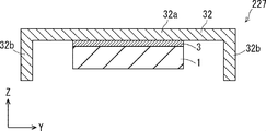
- the piezoelectric vibration unit 227 which is a modification of the piezoelectric vibration unit 207.
- the piezoelectric vibration unit 227 includes a metal diaphragm 32 having the same shape as the shape in which the metal diaphragm 22 and the holder 9 are integrated.
- the main body 32a which may be referred to as a substantially rectangular plate-like portion
- the holding portion 32b are integrated, water and foreign matter that have entered from the frequency adjustment hole 22b and the like are separated from the piezoelectric element 1. Further suppress contact.
- maintenance part 32b are integrated, the piezoelectric vibration unit 227 can be manufactured at low cost.
- the piezoelectric vibration unit 237 is a modification of the piezoelectric vibration unit 207.
- the piezoelectric vibration unit 237 has a metal vibration part 42.
- the metal vibrating part 42 has the same configuration as the metal vibrating plate 32 (see FIG. 7B) except that it has a bottom part 42c.
- the metal vibrating part 42 includes a main body 42a, a holding part 42b, and a bottom part 42c.
- the main body 42a has the same configuration as the main body 32a
- the holding portion 42b has the same configuration as the holding portion 32b.
- the bottom portion 42c is a plate-like body that is integrated with the holding portion 42b and faces the main body 42a.
- the piezoelectric vibration unit 237 since the main body 42a, the holding portion 42b, and the bottom portion 42c are integrated, it is further suppressed that water or foreign matter that has entered from the frequency adjustment hole 22b or the like comes into contact with the piezoelectric element 1.
- the piezoelectric vibration unit 237 has high rigidity because the main body 42a, the holding portion 42b, and the bottom portion 42c are integrated.
- the piezoelectric vibration unit 247 which is a modified example of the piezoelectric vibration unit 207.
- the piezoelectric vibration unit 247 has the same configuration as the piezoelectric vibration unit 227 (see FIG. 7B) except that the bottom plate 8 is included.
- the piezoelectric vibration unit 247 includes a bottom plate 8.
- the bottom plate 8 is a plate-like body that is provided below the lower end of the holding portion 32b and faces the main body 32a. It is good to install so that the outer edge of the baseplate 8 and the lower end of the holding
- the piezoelectric vibration unit 247 includes the bottom plate 8, compared to the piezoelectric vibration unit 227, the piezoelectric vibration unit 247 further suppresses contact of water and foreign matter that have entered from the frequency adjustment hole 22 b and the like with the piezoelectric element 1. Further, since the piezoelectric vibration unit 247 includes the bottom plate 8, it has higher rigidity than the piezoelectric vibration unit 227 (see FIG. 7B).
- FIGS. 8A to 8D are cross-sectional views of a second modification of the main part of the piezoelectric speaker according to the second embodiment.
- the piezoelectric vibration unit 317 is a modification of the piezoelectric vibration unit 207.
- the piezoelectric vibration unit 317 has the same configuration as the piezoelectric vibration unit 217 except for the metal vibration plate 52 and the stepped holder 19.
- the piezoelectric vibration unit 317 includes a metal diaphragm 52 and a stepped holder 19, and the metal diaphragm 52 is bonded to the stepped holder 19 through the bonding portion 3. Further, the metal diaphragm 52 is held by the stepped holder 19.
- the stepped holder 19 is a wall body having a step portion that extends from the bottom of the case 6 (see FIG.
- the stepped holder 19 is disposed so as to cover the periphery of the piezoelectric element 1 so that water and foreign matter do not adhere to the piezoelectric element 1. Since the piezoelectric vibration unit 317 includes the stepped holder 19, water or foreign matter that has entered from the frequency adjustment hole 22 b or the like is prevented from coming into contact with the piezoelectric element 1. In addition, since the piezoelectric vibration unit 317 includes the stepped holder 19, it has a higher pressure resistance than the piezoelectric vibration unit 217.
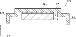
- the piezoelectric vibration unit 327 which is a modification of the piezoelectric vibration unit 207.
- the piezoelectric vibration unit 327 includes a metal vibration plate 62 having the same shape as the shape in which the metal vibration plate 52 and the stepped holder 19 are integrated.
- the main body 62a may be referred to as a substantially rectangular plate-like portion
- the holding portion 62b are integrated, the frequency adjustment is performed as compared with the piezoelectric vibration unit 317 (see FIG. 8A).
- the piezoelectric vibration unit 327 can be manufactured at a lower cost than the piezoelectric vibration unit 317 because the main body 62a and the holding portion 62b are integrated.
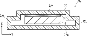
- the piezoelectric vibration unit 337 is a modification of the piezoelectric vibration unit 207.
- the piezoelectric vibration unit 337 has a metal vibration part 72.
- the metal vibrating part 72 has the same configuration as the metal vibrating plate 62 (see FIG. 8B) except that it has a bottom part 72c.
- the metal vibrating part 72 includes a main body 72a, a holding part 72b, and a bottom part 72c.
- the main body 72a has the same configuration as the main body 62a
- the holding portion 72b has the same configuration as the holding portion 62b.
- the bottom portion 72c is a plate-like body that is integrated with the holding portion 72b and faces the main body 72a.
- the piezoelectric vibration unit 337 since the main body 72a, the holding portion 72b, and the bottom portion 72c are integrated, water and foreign matter that have entered from the frequency adjustment hole 22b and the like come into contact with the piezoelectric element 1 compared to the piezoelectric vibration unit 317. This is further suppressed.
- the piezoelectric vibration unit 337 has higher rigidity than the piezoelectric vibration unit 317 because the main body 72a, the holding portion 72b, and the bottom portion 72c are integrated.
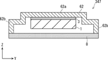
- FIG. 8D there is a piezoelectric vibration unit 347 that is a modification of the piezoelectric vibration unit 207.
- the piezoelectric vibration unit 347 has the same configuration as that obtained by adding the bottom plate 8 to the piezoelectric vibration unit 327 (see FIG. 8B). Since the piezoelectric vibration unit 347 includes the bottom plate 8, compared to the piezoelectric vibration unit 327 (see FIG. 8B), the piezoelectric vibration unit 347 further suppresses contact of water and foreign matter that have entered from the frequency adjustment hole 22 b and the like with the piezoelectric element 1. In addition, since the piezoelectric vibration unit 247 includes the bottom plate 8, it has higher rigidity than the piezoelectric vibration unit 327.
- FIGS. 9A to 9D are cross-sectional views of a third modification of the main part of the piezoelectric speaker according to the second embodiment.
- the piezoelectric vibration unit 417 is a modification of the piezoelectric vibration unit 207.
- the piezoelectric vibration unit 417 has the same configuration as that of the piezoelectric vibration unit 217 (see FIG. 7A) except that the piezoelectric vibration unit 417 includes the metal vibration plate 82.
- the piezoelectric vibration unit 417 includes a metal vibration plate 82, and the metal vibration plate 82 includes a main body 82a and a gripped portion 82d extending from an end of the main body 82a.
- the main body 82 a has the same configuration as that of the metal diaphragm 22, and the end of the main body 82 a is bonded to the holder 9 via the bonding portion 3.
- the gripped portion 82 d extends toward the side wall of the case 6.
- the piezoelectric speaker 200 can be assembled by mounting the piezoelectric vibration unit 417 on the case 6.
- the gripped portion 82d has a shape extending from the end of the main body 82a, it is easy to grip. Further, the shape of the gripped portion 82d may be changed as necessary in order to make it easier to mount the piezoelectric vibration unit 417 on the case 6. Since the piezoelectric vibration unit 417 includes the metal vibration plate 82 and the holder 9, water or foreign matter that has entered from the frequency adjustment hole 22 b or the like is prevented from coming into contact with the piezoelectric element 1. In addition, since the piezoelectric vibration unit 417 includes the metal vibration plate 82, it can be easily mounted as compared with the piezoelectric vibration unit 217 (see FIG. 7A).
- the piezoelectric vibration unit 427 includes a metal vibration plate 92 having the same shape as the shape in which the metal vibration plate 82 and the holder 9 are integrated.
- the piezoelectric vibration unit 427 since the main body 92a, the holding portion 92b, and the gripped portion 92d are integrated, water or foreign matter that has entered from the frequency adjustment hole 22b or the like compared to the piezoelectric vibration unit 417 (see FIG. 9A). Is further suppressed from contacting the piezoelectric element 1.
- the piezoelectric vibration unit 427 can be manufactured at a lower cost than the piezoelectric vibration unit 417 (see FIG. 9A).
- the piezoelectric vibration unit 437 which is a modified example of the piezoelectric vibration unit 207.
- the piezoelectric vibration unit 437 includes the metal vibration unit 102.
- the metal vibrating portion 102 has the same configuration as the metal vibrating plate 92 (see FIG. 9B) except that it has a bottom portion 102c.
- the metal vibrating part 102 includes a main body 102a, a holding part 102b, and a bottom part 102c.
- the main body 102a has the same configuration as the main body 92a
- the holding portion 102b has the same configuration as the holding portion 92b.
- the bottom portion 102c is a plate-like body that is integrated with the holding portion 102b and faces the main body 102a.
- the piezoelectric vibration unit 437 since the main body 102a, the holding portion 102b, and the bottom portion 102c are integrated, water or foreign matter that has entered from the frequency adjustment hole 22b or the like comes into contact with the piezoelectric element 1 as compared with the piezoelectric vibration unit 417. Is further suppressed.
- the piezoelectric vibration unit 437 has higher rigidity than the piezoelectric vibration unit 417 because the main body 102a, the holding portion 102b, and the bottom portion 102c are integrated.
- FIG. 9D there is a piezoelectric vibration unit 447 which is a modified example of the piezoelectric vibration unit 207.
- the piezoelectric vibration unit 447 has the same configuration as that obtained by adding the bottom plate 8 to the piezoelectric vibration unit 427 (see FIG. 9B). Since the piezoelectric vibration unit 447 includes the bottom plate 8, water and foreign matter that have entered from the frequency adjustment hole 22 b and the like, as compared with the piezoelectric vibration unit 427 (see FIG. 9D), like the piezoelectric vibration unit 247 (see FIG. 7D). Is further suppressed from contacting the piezoelectric element 1. In addition, since the piezoelectric vibration unit 447 includes the bottom plate 8, it has higher rigidity than the piezoelectric vibration unit 427.
- FIGS. 10A to 10D are cross-sectional views of Modification 4 of the main part of the piezoelectric speaker according to the second embodiment.
- the piezoelectric vibration unit 517 is a modification of the piezoelectric vibration unit 207.
- the piezoelectric vibration unit 517 has the same configuration as the piezoelectric vibration unit 217 except that it has a tapered holder 29 instead of the holder 9.
- the piezoelectric vibration unit 517 includes a tapered holder 29, and the end of the metal diaphragm 22 is bonded to the tapered holder 29 via the bonding portion 3.
- the metal diaphragm 22 is held by a tapered holder 29.
- the tapered holder 29 is a wall extending from the bottom of the case 6 (see FIG. 2) toward the metal diaphragm 22.
- the tapered holder 29 has a tapered shape, and the tapered shape has a cross-sectional area that increases from the bottom of the case 6 toward the metal diaphragm 22. More specifically, the taper shape is inclined toward the piezoelectric element 1 side.
- the holder 9 is disposed so as to cover the periphery of the piezoelectric element 1 so that water and foreign matter do not adhere to the piezoelectric element 1. Since the piezoelectric vibration unit 517 has the taper-shaped holding tool 29, it prevents the water and foreign matter that have entered from the frequency adjustment hole 22 b and the like from coming into contact with the piezoelectric element 1.
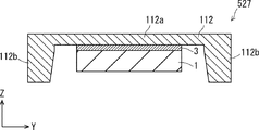
- the piezoelectric vibration unit 527 that is a modification of the piezoelectric vibration unit 207.
- the piezoelectric vibration unit 527 includes a metal vibration plate 112 having the same shape as the shape in which the metal vibration plate 22 and the tapered holder 29 are integrated.
- the piezoelectric vibration unit 527 since the main body 112a and the holding portion 12b are integrated, water or foreign matter that has entered from the frequency adjustment hole 22b or the like contacts the piezoelectric element 1 as compared with the piezoelectric vibration unit 517 (see FIG. 10A). To further suppress.
- the piezoelectric vibration unit 527 can be manufactured at a lower cost than the piezoelectric vibration unit 517 because the main body 112a and the holding portion 12b are integrated.
- the piezoelectric vibration unit 537 includes a metal vibration unit 122.
- the metal vibrating part 122 has the same configuration as the metal vibrating plate 112 (see FIG. 10B) except that it has a bottom part 122c.
- the metal vibrating part 122 includes a main body 122a, a holding part 122b, and a bottom part 122c.
- the main body 122a has the same configuration as the main body 112a
- the holding portion 122b has the same configuration as the holding portion 112b.
- the bottom portion 122c is a plate-like body that is integrated with the holding portion 122b and faces the main body 122a.
- the piezoelectric vibration unit 537 since the main body 12a, the holding portion 122b, and the bottom portion 122c are integrated, water or foreign matter that has entered from the frequency adjustment hole 22b or the like is less than the piezoelectric vibration unit 517 (see FIG. 10A). 1 is further suppressed.
- the piezoelectric vibration unit 537 has higher rigidity than the piezoelectric vibration unit 517 because the main body 102a, the holding portion 102b, and the bottom portion 102c are integrated.
- FIG. 10D there is a piezoelectric vibration unit 547 that is a modification of the piezoelectric vibration unit 207.
- the piezoelectric vibration unit 547 has the same configuration as that obtained by adding the bottom plate 8 to the piezoelectric vibration unit 527 (see FIG. 10B). Since the piezoelectric vibration unit 547 includes the bottom plate 8, water and foreign matter that have entered from the frequency adjustment hole 22 b and the like, as compared with the piezoelectric vibration unit 527 (see FIG. 10D), like the piezoelectric vibration unit 247 (see FIG. 7D). Is further suppressed from contacting the piezoelectric element 1. In addition, since the piezoelectric vibration unit 547 includes the bottom plate 8, it has higher rigidity than the piezoelectric vibration unit 527.
- FIGS. 11A and 11B are cross-sectional views of Modification 5 of the main part of the piezoelectric speaker according to the second embodiment.
- the piezoelectric vibration unit 637 that is a modification of the piezoelectric vibration unit 207.
- the piezoelectric vibration unit 637 has the same configuration as the piezoelectric vibration unit 237 (see FIG. 7C) except for the metal vibration part 142.
- the piezoelectric vibration unit 637 includes a metal vibration part 142, and the metal vibration part 142 has the same configuration as the metal vibration part 42 (see FIG. 7C) except that the metal vibration part 142 has a vent hole 142e.
- the ventilation hole 142e is installed in the main body 142a, and is connected to a pressure adjustment unit (not shown).
- the pressure adjustment unit is, for example, a compressor.
- the metal vibrating part 142 is maintained so that the pressure in the inner space of the metal vibrating part 142 becomes constant by supplying or discharging the pressure adjusting gas from the vent hole 142e.
- the piezoelectric vibration unit 637 the main body 142a, the holding portion 142b, and the bottom portion 142c are integrated, and the pressure in the inner space is kept constant. Further suppress contact.
- the piezoelectric vibration unit 637 has high rigidity because the main body 142a, the holding portion 142b, and the bottom portion 142c are integrated.
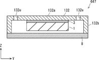
- the piezoelectric vibration unit 647 that is a modification of the piezoelectric vibration unit 207.
- the piezoelectric vibration unit 647 has the same configuration as the piezoelectric vibration unit 247 (see FIG. 7D) except for the metal vibration plate 132.
- the piezoelectric vibration unit 647 includes a metal vibration plate 132, and the metal vibration plate 132 has the same configuration as the metal vibration plate 32 (see FIG. 7D) except that it has a vent hole 132e.
- the ventilation hole 132e is installed in the main body 132a and is connected to a pressure adjustment unit (not shown).
- the pressure adjustment unit is, for example, a compressor.
- the metal diaphragm 132 is maintained so that the pressure in the inner space of the metal diaphragm 132 becomes constant by supplying or discharging the pressure adjusting gas from the vent hole 132e.
- the piezoelectric vibration unit 647 includes the metal vibration plate 132 and the bottom plate 8 and further keeps the pressure in the inner space constant, and thus further suppresses water and foreign matter entering from the frequency adjustment hole 22b and the like from coming into contact with the piezoelectric element 1. . Moreover, since the piezoelectric vibration unit 647 includes the bottom plate 8, it has higher rigidity than the piezoelectric vibration unit 227 (see FIG. 7B).
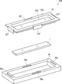
- FIG. 12A is an exploded perspective view of a modification of the piezoelectric speaker according to the third embodiment.
- the piezoelectric speaker according to the third embodiment has the same configuration as that of the piezoelectric speaker 100 according to the first embodiment except for the metal diaphragm 2 (see FIG. 2), the adhesive portion 4 and the cover 5.
- the piezoelectric speaker 300 includes a metal diaphragm 152, a cover 15, and a case 16.
- the metal diaphragm 152 has the same configuration as that of the metal diaphragm 2 (see FIG. 2) except that the metal diaphragm 152 is integrated with the cover 15.
- the cover 15 has the same configuration as the cover 5 (see FIG. 2) except that the cover 15 is integrated with the metal diaphragm 152.
- the integrated cover 15 and metal diaphragm 152 can be obtained, for example, by drawing a single plate material. Therefore, the cover 15 and the metal diaphragm 152 can be integrally manufactured by performing one process on the integrated material, so that the material cost and the processing cost can be reduced.
- the piezoelectric speaker 300 does not include the bonding portion 4.
- the case 16 is a rectangular frame.
- the piezoelectric speaker 300 may include the case 6 (see FIG. 2) instead of the case 16.
- the material cost and the processing cost can be reduced and the manufacturing cost can be reduced while omitting the bonding portion.
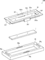
- FIGS. 12B and 12C are exploded perspective views of a modification of the piezoelectric speaker according to the third exemplary embodiment.
- the piezoelectric speaker 400 which is a modification of the piezoelectric speaker 300.
- the piezoelectric speaker 400 has the same configuration as the piezoelectric speaker 300 except for a cover and a case.
- the cover 25 has the same configuration as the cover 15 except that it includes a locking piece 25f
- the case 26 has the same configuration as the case 16 except that it includes a locking hole 26g.
- the cover 25 includes a locking piece 25f
- the case 26 includes a locking hole 26g.
- the locking piece 25f is disposed in the vicinity of the outer edge of the cover 25, specifically, in the shape corresponding to the shape of the cover 25, that is, in the vicinity of the center of each side of the rectangle.
- the locking piece 25f extends toward the case 16 side.
- the locking piece 25f is formed, for example, using press working after the metal diaphragm 252 is formed using drawing.
- the locking hole 26g is provided on the contact surface of the cover 25 that contacts the case 26 so as to correspond to the locking piece 25f.
- the piezoelectric speaker 500 is a modification of the piezoelectric speaker 300.
- the piezoelectric speaker 500 has the same configuration as the piezoelectric speaker 400 (see FIG. 12B) except for the metal diaphragm.
- the metal diaphragm 352 has the same configuration as the metal diaphragm 252 except that it includes a frequency adjusting hole 352e.
- the metal diaphragm 352 includes a frequency adjusting hole 352e.
- the frequency adjusting hole 352e is installed at a location corresponding to the locking piece 35f.
- the frequency adjusting hole 352e is provided in the vicinity of the outer edge of the metal diaphragm 325, specifically, in the shape corresponding to the shape of the cover 35, that is, in the vicinity of the center of each side of the rectangle.
- FIG. 13 is a graph illustrating sound pressure with respect to frequency in the example of the piezoelectric speaker according to the first embodiment.
- Example 1 and Example 2 a piezoelectric speaker having the same configuration as that of the piezoelectric speaker 100 according to the first embodiment was used. Specifically, in Example 1 and Example 2, a plate made of brass and having a thickness of 1 mm was used as the metal diaphragm 2 (see FIG. 2). In Example 1, a double-sided tape is used as the bonding part 4 (see FIG. 2), and in Example 2, an epoxy resin body formed by curing an epoxy resin agent is used as the bonding part 4 (see FIG. 2). Using.
- the double-sided tape used in Example 1 is a belt-like base material having a predetermined elastic modulus, and both main surfaces of the base material are coated with an adhesive and have adhesiveness. Moreover, this base material has a low elastic modulus compared with an epoxy resin.
- Example 1 the sound pressure reaches the maximum value in the frequency region 20 kHz to 30 kHz.
- the sound pressure characteristic curve of Example 1 is within a predetermined range of about 79 dB sql to about 93 dB sql in the frequency region from 20 kHz to 100 kHz. That is, in the first embodiment, sound can be reproduced with a stable sound pressure in the frequency region from 20 kHz to 100 kHz.
- the sound pressure reaches the maximum value in the frequency region of about 30 kHz.
- the first embodiment has a tendency that the sound pressure rises faster than the second embodiment.
- One reason for this is thought to be that the double-sided tape used as the adhesive portion in Example 1 is harder than an epoxy resin body formed by curing an epoxy resin.
- the sound pressure characteristic curve of Example 2 is within a predetermined range of about 79 dB sql to about 93 dB sql in the frequency region from about 25 kHz to 100 kHz. That is, also in the second embodiment, it is possible to reproduce sound with a stable sound pressure in the frequency region from 20 kHz to 100 kHz.
- Example using the silicone resin body formed by hardening a silicone adhesive as the adhesion part 4 (refer FIG. 2) can also be considered.
- FIG. 17 is an XZ sectional view showing the configuration of the speaker unit 700.
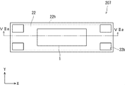
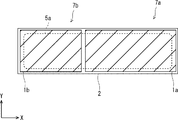
- FIG. 18 is a bottom view showing the configuration of the main part of the speaker unit 700.
- two piezoelectric vibration units 7 a and 7 b are arranged in the case 6. Since the basic configuration other than the two piezoelectric vibration units 7a and 7b is the same as that of the speaker units 100, 200, 300, 400, and 500 of the above-described embodiment, the description thereof will be omitted as appropriate.
- the case 6, the bonding part 3, the metal diaphragm 2, and the like can be the same as those shown in FIGS. 1 and 3.
- piezoelectric vibration units 7a and 7b are accommodated.
- the piezoelectric vibration unit 7a includes a piezoelectric element 1a, an adhesive portion 3a, and a metal vibration plate 2.
- the piezoelectric element 1a is bonded to the metal diaphragm 2 via the bonding portion 3a.
- the piezoelectric vibration unit 7b includes a piezoelectric element 1b, an adhesive portion 3b, and a metal vibration plate 2. Similar to the first embodiment, the piezoelectric element 1b is bonded to the metal diaphragm 2 through the bonding portion 3b.
- the metal diaphragm 2 is common to the two piezoelectric vibration units 7a and 7b. That is, the metal diaphragm 2 has a single metal plate, and the piezoelectric elements 1a and 1b are attached to the single metal plate.
- the piezoelectric elements 1 a and 1 b are attached to the same surface of the metal diaphragm 2. Specifically, the piezoelectric elements 1a and 1b are attached to the surface of the metal diaphragm 2 opposite to the sound emission hole 5a side.
- the piezoelectric elements 1a and 1b are distorted. Thereby, the metal diaphragm 2 vibrates and a sound is generated from the sound emission hole 5a.
- the two piezoelectric elements 1a and 1b are arranged side by side in the X direction. That is, the piezoelectric element 1a is arranged on the + X side of the piezoelectric element 1b.
- the piezoelectric elements 1a and 1b overlap the sound emitting hole 5a. Furthermore, a part of the piezoelectric elements 1a and 1b protrudes from the sound emission hole 5a.
- the piezoelectric elements 1a and 1b are substantially rectangular.
- the two piezoelectric elements 1a and 1b have different sizes. Specifically, the two piezoelectric elements 1a and 1b have different widths in the X direction. The two piezoelectric elements 1a and 1b have the same width in the Y direction. The two piezoelectric elements 1a and 1b have different natural vibration mode frequencies. That is, the resonance frequency of the piezoelectric element 1a is different from the resonance frequency of the piezoelectric element 1b. The frequency of the natural vibration mode of the piezoelectric elements 1 a and 1 b is different from the frequency of the natural vibration mode of the metal diaphragm 2.
- two piezoelectric elements 1a and 1b having different resonance frequencies are connected to the metal diaphragm 2 via the bonding portions 3a and 3b.
- a high sound pressure and a high SN ratio can be obtained even in a high frequency range of 5 kHz to 50 kHz. Therefore, a high performance speaker unit can be realized with a simple structure.
- the SN ratio of a general electromagnetic speaker is 45 dB, whereas the piezoelectric speaker unit 700 can achieve an SN ratio of 60 dB.
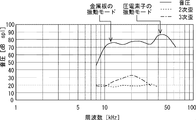
- the frequency characteristics of the sound pressure of the piezoelectric speaker unit 700 are shown in FIG.
- the frequency characteristic of the sound pressure of the piezoelectric speaker unit 700 is shown as an example.
- the frequency characteristic when a dynamic speaker (electromagnetic speaker) and an LPF (Low Pass Filter) are used is shown as Comparative Example 1
- Comparative Example 2 the frequency characteristic of a piezoelectric speaker unit having one piezoelectric element is shown as Comparative Example 2. Show. Compared with Comparative Examples 1 and 2, the piezoelectric speaker unit 700 can obtain a high sound pressure even in a high frequency region of 5 kHz or more.
- the piezoelectric elements 1a and 1b having different dimensions have different resonance frequencies.
- the flatness of the sound pressure frequency characteristics can be optimized by combining the shapes of the rectangular piezoelectric elements 1 a and 1 b and the metal diaphragm 2.
- the two piezoelectric elements 1a and 1b are provided, but three or more piezoelectric elements can be provided. That is, it is only necessary that the plurality of piezoelectric elements 1 are bonded to the metal diaphragm 2 via the bonding portion 3.
- the resonance frequency Qm of the piezoelectric element in the range of 1.0 to 5.0 by using an elastic body for the bonding portion 3. Thereby, it is possible to reproduce the sound with a wide frequency band and a flat sound pressure characteristic curve.
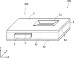
- FIG. 20 is a perspective view showing the external appearance of the piezoelectric speaker unit 800.
- FIG. 21 is an XY plan view showing a configuration in the internal space of the housing 820 of the piezoelectric speaker unit 800.
- an electromagnetic speaker 810 is provided inside the case 6 of FIG.
- the piezoelectric element 1 is provided outside the case 6. Note that the description of the same configuration as in the first to fourth embodiments will be omitted as appropriate.
- the housing 820 has a box shape.
- the housing 820 includes a case 6 and a cover 5.
- the case 6 includes a side plate 6d and a back plate 6e.
- the back plate 6 e faces the cover 5.
- the cover 5 and the back plate 6e are flat plates parallel to each other.
- the cover 5, the side plate 6d, and the back plate 6e are each preferably a rectangular metal plate.
- the cover 5 has a sound emission hole 5a.
- the cross-sectional shape of the sound emission hole 5a is a taper shape that becomes larger toward the outside as in the configuration shown in FIG.
- the side where the sound emission hole 5a is provided is described as the front side.
- the back plate 6e is disposed to face the cover 5.
- the side plate 6d is disposed between the cover 5 and the back plate 6e. That is, the side plate 6d connects the cover 5 and the back plate 6e.
- the case 6 has four side plates 6d. That is, the side plate 6d is disposed on each end of the substantially rectangular cover 5 and the back plate 6e.
- the opposing two side plates 6d are parallel to each other. Two adjacent side plates 6d are orthogonal to each other.
- the internal space of the housing 820 is defined as an air chamber 6f. That is, the space defined by the cover 5, the back plate 6e, and the side plate 6d becomes the air chamber 6f. Specifically, a rectangular parallelepiped space surrounded by the cover 5, the back plate 6e, and the four side plates 6d becomes the air chamber 6f.
- the air chamber 6 f is connected to the external space through the sound emission hole 5.
- the cover 5 and the back plate 6e are arranged to face each other through the air chamber 6f. Therefore, the cover 5 serves as a front plate for defining the air chamber 6f.
- cover 5, the back plate 6e, and the side plate 6d may be integrally formed.
- the back plate 6e and the side plate 6d may be integrally formed.
- the cover 5 may be removable like the cover 5 of Embodiment 1. FIG. Of course, other than the cover 5 may be removable.
- An electromagnetic speaker 810 is arranged in the air chamber 6f.
- an electromagnetic speaker 801 is attached to one side plate 6d.
- the electromagnetic speaker 810 is installed on the surface (hereinafter referred to as the inner surface) on the air chamber 6f side of the side plate 6d on the -Y side.
- the electromagnetic speaker 810 includes a diaphragm, a voice coil, a permanent magnet, and the like. By supplying current to the voice coil, the voice coil and the diaphragm vibrate. As a result, the electromagnetic speaker 810 generates sound.
- the electromagnetic speaker 810 generates sound toward the sound emission hole 5a.
- the piezoelectric element 1 is provided outside the case 6.
- the piezoelectric element 1 is bonded to the side plate 6 d of the case 6 through the bonding portion 3.
- the bonding part 3 is an elastic body as described above.
- the piezoelectric element 1 is attached to a surface opposite to the air chamber 6f side of the side plate 6d (hereinafter referred to as an outer surface).
- the inner surface of one side plate 6 d is a mounting surface for the electromagnetic speaker 810
- the outer surface is a mounting surface for the piezoelectric element 1.
- the piezoelectric element 1 is disposed on one of the two opposing surfaces of the side plate 6d (outer surface), and the electromagnetic speaker 810 is disposed on the other surface (inner surface).
- the mounting surface of the piezoelectric element 1 and the mounting surface of the electromagnetic speaker 801 are facing surfaces of the case 6.
- an electromagnetic speaker 810 is fixed to the case 6. Both the electromagnetic speaker 810 mounted on the case 6 and the piezoelectric element 1 vibrate.
- the frequency of the natural vibration mode of the electromagnetic speaker 810 is different from the frequency of the natural vibration mode of the piezoelectric element 1. Therefore, a high sound pressure and a high S / N ratio can be realized even in a high frequency region. With the configuration of the present embodiment, it is possible to reproduce sound in a wide band from 100 Hz to 100 kHz.
- the side plate 6d serving as a mounting surface for mounting the piezoelectric element 1 is formed of a metal plate. That is, the side plate 6 d, the bonding portion 3, and the piezoelectric element 1 constitute the piezoelectric vibration unit 7. By doing so, the side plate 6d functions as the metal vibrating portion 2 of the first embodiment or the like. Therefore, high sound pressure and high S / N ratio can be realized in the high frequency region as in the first embodiment. In the present embodiment, the piezoelectric vibration unit 7 does not block the sound emission hole 5a.
- the side plate 6d serving as a mounting surface on which the piezoelectric element 1 is mounted is preferably formed of a metal plate having a thickness of 10 to 300 ⁇ m. By so doing, higher sound pressure and higher SN ratio can be realized in the high frequency region.
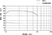
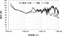
- FIG. 22 is a graph showing frequency characteristics of sound pressure of the piezoelectric speaker unit 800 according to the present embodiment.
- the sound pressure frequency characteristic in the configuration in which only the electromagnetic speaker 810 is mounted is shown as “electromagnetic”.
- a sound pressure frequency characteristic in a configuration in which only the piezoelectric element 1 is mounted is shown as “piezoelectric”.
- the sound pressure frequency characteristic of the electromagnetic speaker 810 on which both the piezoelectric element 1 and the electromagnetic speaker 810 are mounted is shown as “electromagnetic + piezoelectric”.
- reproduction at a high sound pressure is possible even at 20 kHz or higher.
- a high sound pressure and a high S / N ratio can be realized even in a high frequency region.
- FIG. 23 is an XY cross-sectional view showing the main parts of a piezoelectric speaker unit 800 according to Modification 6.
- the position of the piezoelectric element 1 is different from that of the fifth embodiment.
- the piezoelectric element 1 is disposed in the housing 820. Note that the basic configuration of the piezoelectric speaker unit 800 is the same as described above, and thus description thereof will be omitted as appropriate.
- the piezoelectric element 1 is disposed in the air chamber 6f. That is, the piezoelectric element 1 is attached to the inner surface of the side plate 6d via the bonding portion 3.
- the inner surface of the side plate 6 d on the ⁇ Y side is the mounting surface of the piezoelectric element 1. Therefore, the electromagnetic speaker 810 and the piezoelectric element 1 are installed on the same surface (inner surface) of the side plate 6d.
- the mounting surface of the piezoelectric element 1 and the mounting surface of the electromagnetic speaker 801 are the same surface of the case 6.
- both the electromagnetic speaker 810 and the piezoelectric element 1 mounted on the case 6 vibrate.
- the frequency of the natural vibration mode of the electromagnetic speaker 810 is different from the frequency of the natural vibration mode of the piezoelectric element 1.
- the side plate 6d serving as a mounting surface for mounting the piezoelectric element 1 is formed of a metal plate. That is, the side plate 6 d, the bonding portion 3, and the piezoelectric element 1 constitute the piezoelectric vibration unit 7. By so doing, high sound pressure and high S / N ratio can be realized in the high frequency region as in the first embodiment.
- the side plate 6d serving as a mounting surface on which the piezoelectric element 1 is mounted is preferably formed of a metal plate having a thickness of 10 to 300 ⁇ m. By so doing, higher sound pressure and higher SN ratio can be realized in the high frequency region.
- FIG. 24 is a YZ cross-sectional view showing the main part of the piezoelectric speaker unit 800 according to Modification 7.
- the positions of the piezoelectric element 1 and the electromagnetic speaker 810 are different from the configuration of the fifth embodiment.
- the basic configuration of the piezoelectric speaker unit 800 is the same as described above, and thus description thereof will be omitted as appropriate.
- an electromagnetic speaker 810 is attached to the back plate 6e. Specifically, an electromagnetic speaker 810 is fixed to the inner surface of the back plate 6e. Therefore, the electromagnetic speaker 810 is disposed in the air chamber 6f. The electromagnetic speaker 810 generates sound toward the sound emission hole 5a.
- the piezoelectric element 1 is bonded to the back plate 6e and the cover 5. Specifically, adhesive portions 3 made of an elastic body are provided on both surfaces of the piezoelectric element 1.
- the back surface of the piezoelectric element 1 is bonded to the back plate 6 e via the bonding portion 3.
- the back plate 6e serving as the mounting surface of the piezoelectric element 1 is preferably a metal plate having a thickness of 10 to 300 ⁇ m.
- the front surface of the piezoelectric element 1 is bonded to the metal diaphragm 2 through the bonding portion 3.
- An adhesive portion 4 is provided on the front surface of the metal diaphragm 2.
- the metal diaphragm 2 is bonded to the cover 5 via the bonding portion 4.
- the bonding portion 4 is attached to the outer edge portion 2 h of the metal diaphragm 2. Therefore, when the piezoelectric speaker 100 is viewed from the cover 5 side, the outer edge 2 h is covered with the cover 5.
- the adhesive portion 4 is provided except for a portion corresponding to the sound emission hole 5 a of the cover 5. Therefore, when the piezoelectric speaker 100 is viewed from the cover 5 side, the metal diaphragm 2 can be seen from the sound emitting hole 5a.
- the metal diaphragm 2 that is the mounting surface of the piezoelectric element 1 is preferably a metal plate having a thickness of 10 to 300 ⁇ m.
- the adhesive portion 3 is provided on the front surface and the back surface of the piezoelectric element 1. That is, the piezoelectric element 1 is sandwiched between the two bonding portions 3. Then, both surfaces of the piezoelectric element 1 are fixed to the housing 820 via the bonding portion 3.
- the back plate 6 e, the bonding part 3, the piezoelectric element 1, the bonding part 3, and the metal diaphragm 2 constitute a piezoelectric vibration unit 7.
- both the electromagnetic speaker 810 and the piezoelectric element 1 mounted on the case 6 vibrate.
- the frequency of the natural vibration mode of the electromagnetic speaker 810 is different from the frequency of the natural vibration mode of the piezoelectric element 1.
- a metal diaphragm 2 serving as a mounting surface of the piezoelectric element 1 is fixed to another member (cover 5) through an adhesive portion 4 which is an elastic body. Therefore, good characteristics can be obtained as in the above-described embodiment. Further, the surface on which the metal diaphragm 2 is mounted is not limited to the cover 5.
- the metal plate (metal vibrating portion 2) may be fixed to the side plate 6d or the back plate 6e via the adhesive portion 3 that is an elastic body.
- FIG. 25 is a YZ cross-sectional view showing the main parts of the piezoelectric speaker unit 800 according to Modification 8.
- the configuration of the back plate 6e is different from the configuration of the modified example 7.
- the basic configuration of the piezoelectric speaker unit 800 is the same as described above, and thus description thereof will be omitted as appropriate.
- the back plate 6e is a metal plate, but in the modified example 8, a part of the back plate 6e is a resin 6g. That is, the back plate 6e is composed of a metal material and a resin material. That is, a part of the back plate 6e is formed of a resin material, and the rest is formed of a metal material. Therefore, since a part of the back plate 6e serving as the mounting surface is formed of the resin 6g in this way, the back plate 6e is a partial metal plate.
- the side plate 6d, the cover 5, or the back plate 6e serves as a mounting surface of the pressure element 1, and includes a metal material and a resin material. Thus, good characteristics can be obtained.
- the piezoelectric element 1 is fixed to the case 6 via the adhesive portion 3 that is an elastic body. However, the piezoelectric element 1 is not connected to the elastic body. May be fixed to the case 6.
- the mounting surface of the piezoelectric element 1 is the side plate 6d, and in Modifications 7 and 8, the back plate 6e is used.
- the mounting surface of the piezoelectric element 1 is not particularly limited. Absent. Further, the piezoelectric element 1 may be attached to the outer surface of the housing 820.
- the electromagnetic speaker 810 is disposed inside the case 6 and two or more piezoelectric elements 1 are mounted on the case 6.
- the piezoelectric speakers according to the first to fifth embodiments described above can be used by being incorporated into various devices.
- the piezoelectric speaker described above can be used as a high-frequency speaker incorporated in a PC (personal computer), a tablet PC, a next-generation 4K television, a next-generation 8K television, a vehicle-mounted type, and a stationary high-resolution audio.
- the need for loudspeakers that can reproduce with high sound pressure and high signal-to-noise ratio at high frequencies of 20 kHz to 70 kHz is increasing due to digital sound, sound source sampling frequency information in music reproduction, and expansion of the number of bits.
- a high frequency of 20 kHz or higher cannot be heard by humans, in fact, being able to reproduce up to a high frequency leads to reproducing up to a minute signal.
- Higher quality sound sources can contribute to higher speaker output.
- wirings connected to piezoelectric elements and electromagnetic speakers are omitted.
- Piezoelectric vibration unit 1 Piezoelectric element 2, 22, 32, 42, 52, 62, 72, 82, 102, 112, 132, 142, 152, 252, 352
Landscapes
- Engineering & Computer Science (AREA)
- Physics & Mathematics (AREA)
- Acoustics & Sound (AREA)
- Signal Processing (AREA)
- Multimedia (AREA)
- Health & Medical Sciences (AREA)
- Otolaryngology (AREA)
- Piezo-Electric Transducers For Audible Bands (AREA)
Abstract
Priority Applications (4)
| Application Number | Priority Date | Filing Date | Title |
|---|---|---|---|
| CN201680008138.3A CN107431863B (zh) | 2015-02-10 | 2016-01-07 | 压电扬声器 |
| US15/548,271 US20180041839A1 (en) | 2015-02-10 | 2016-01-07 | Piezoelectric speaker |
| KR1020177023054A KR20170107495A (ko) | 2015-02-10 | 2016-01-07 | 압전 스피커 |
| EP16748855.0A EP3258706A1 (fr) | 2015-02-10 | 2016-01-07 | Haut-parleur piézoélectrique |
Applications Claiming Priority (4)
| Application Number | Priority Date | Filing Date | Title |
|---|---|---|---|
| JP2015-024041 | 2015-02-10 | ||
| JP2015024041 | 2015-02-10 | ||
| JP2015106550A JP6195869B2 (ja) | 2015-02-10 | 2015-05-26 | 圧電スピーカ |
| JP2015-106550 | 2015-05-26 |
Publications (1)
| Publication Number | Publication Date |
|---|---|
| WO2016129202A1 true WO2016129202A1 (fr) | 2016-08-18 |
Family
ID=56614455
Family Applications (1)
| Application Number | Title | Priority Date | Filing Date |
|---|---|---|---|
| PCT/JP2016/000049 Ceased WO2016129202A1 (fr) | 2015-02-10 | 2016-01-07 | Haut-parleur piézoélectrique |
Country Status (1)
| Country | Link |
|---|---|
| WO (1) | WO2016129202A1 (fr) |
Cited By (3)
| Publication number | Priority date | Publication date | Assignee | Title |
|---|---|---|---|---|
| CN116528133A (zh) * | 2022-10-25 | 2023-08-01 | 神谱科技股份有限公司 | 电声换能器装置 |
| JP2024505117A (ja) * | 2021-09-07 | 2024-02-02 | 山東華菱電子股フン有限公司 | スピーカシステム及びその応用方法 |
| JP7455533B2 (ja) | 2019-09-05 | 2024-03-26 | Tdk株式会社 | 音響デバイス |
Citations (3)
| Publication number | Priority date | Publication date | Assignee | Title |
|---|---|---|---|---|
| JP2014060478A (ja) * | 2012-09-14 | 2014-04-03 | Kyocera Corp | 音響発生器、音響発生装置および電子機器 |
| JP2014082792A (ja) * | 2012-05-01 | 2014-05-08 | Kyocera Corp | 電子機器 |
| WO2014103454A1 (fr) * | 2012-12-28 | 2014-07-03 | 京セラ株式会社 | Émetteur sonore et appareil électronique l'utilisant |
-
2016
- 2016-01-07 WO PCT/JP2016/000049 patent/WO2016129202A1/fr not_active Ceased
Patent Citations (3)
| Publication number | Priority date | Publication date | Assignee | Title |
|---|---|---|---|---|
| JP2014082792A (ja) * | 2012-05-01 | 2014-05-08 | Kyocera Corp | 電子機器 |
| JP2014060478A (ja) * | 2012-09-14 | 2014-04-03 | Kyocera Corp | 音響発生器、音響発生装置および電子機器 |
| WO2014103454A1 (fr) * | 2012-12-28 | 2014-07-03 | 京セラ株式会社 | Émetteur sonore et appareil électronique l'utilisant |
Cited By (4)
| Publication number | Priority date | Publication date | Assignee | Title |
|---|---|---|---|---|
| JP7455533B2 (ja) | 2019-09-05 | 2024-03-26 | Tdk株式会社 | 音響デバイス |
| JP2024505117A (ja) * | 2021-09-07 | 2024-02-02 | 山東華菱電子股フン有限公司 | スピーカシステム及びその応用方法 |
| JP7639181B2 (ja) | 2021-09-07 | 2025-03-04 | 山東華菱電子股フン有限公司 | スピーカシステム及びその応用方法 |
| CN116528133A (zh) * | 2022-10-25 | 2023-08-01 | 神谱科技股份有限公司 | 电声换能器装置 |
Similar Documents
| Publication | Publication Date | Title |
|---|---|---|
| JP6195869B2 (ja) | 圧電スピーカ | |
| KR101781901B1 (ko) | 전기 음향 변환 장치 | |
| CN109511027B (zh) | 电声转换装置及电子设备 | |
| US7324655B2 (en) | Electroacoustic transducer | |
| CN107615780B (zh) | 压电式发声体和电声转换装置 | |
| CN1759632A (zh) | 骨传导装置 | |
| KR20170117478A (ko) | 밀폐형 음향 서스펜션 챔버를 구비한 라우드스피커 인클로저 | |
| CN107409259B (zh) | 电子音响变换装置 | |
| JP2007251516A (ja) | スピーカ | |
| WO2016129202A1 (fr) | Haut-parleur piézoélectrique | |
| JP2019029745A (ja) | 電気音響変換装置 | |
| KR102021181B1 (ko) | 전기 음향 변환 장치 | |
| JP6792979B2 (ja) | 電気音響変換装置 | |
| JP3089863B2 (ja) | スピーカ | |
| US11758318B1 (en) | Headphone and headset comprising the same | |
| JP2021027506A (ja) | 電気音響変換装置 | |
| JP2005079806A (ja) | 電気音響変換器 | |
| HK1225887B (zh) | 电声转换装置 |
Legal Events
| Date | Code | Title | Description |
|---|---|---|---|
| 121 | Ep: the epo has been informed by wipo that ep was designated in this application |
Ref document number: 16748855 Country of ref document: EP Kind code of ref document: A1 |
|
| WWE | Wipo information: entry into national phase |
Ref document number: 15548271 Country of ref document: US |
|
| NENP | Non-entry into the national phase |
Ref country code: DE |
|
| ENP | Entry into the national phase |
Ref document number: 20177023054 Country of ref document: KR Kind code of ref document: A |
|
| REEP | Request for entry into the european phase |
Ref document number: 2016748855 Country of ref document: EP |