WO2016129291A1 - 方向性電磁鋼板およびその製造方法 - Google Patents
方向性電磁鋼板およびその製造方法 Download PDFInfo
- Publication number
- WO2016129291A1 WO2016129291A1 PCT/JP2016/000744 JP2016000744W WO2016129291A1 WO 2016129291 A1 WO2016129291 A1 WO 2016129291A1 JP 2016000744 W JP2016000744 W JP 2016000744W WO 2016129291 A1 WO2016129291 A1 WO 2016129291A1
- Authority
- WO
- WIPO (PCT)
- Prior art keywords
- annealing
- steel sheet
- grain
- oriented electrical
- electrical steel
- Prior art date
- Legal status (The legal status is an assumption and is not a legal conclusion. Google has not performed a legal analysis and makes no representation as to the accuracy of the status listed.)
- Ceased
Links
Images


Classifications
-
- C—CHEMISTRY; METALLURGY
- C21—METALLURGY OF IRON
- C21D—MODIFYING THE PHYSICAL STRUCTURE OF FERROUS METALS; GENERAL DEVICES FOR HEAT TREATMENT OF FERROUS OR NON-FERROUS METALS OR ALLOYS; MAKING METAL MALLEABLE, e.g. BY DECARBURISATION OR TEMPERING
- C21D8/00—Modifying the physical properties of ferrous metals or ferrous alloys by deformation combined with, or followed by, heat treatment
- C21D8/12—Modifying the physical properties of ferrous metals or ferrous alloys by deformation combined with, or followed by, heat treatment during manufacturing of articles with special electromagnetic properties
- C21D8/1294—Modifying the physical properties of ferrous metals or ferrous alloys by deformation combined with, or followed by, heat treatment during manufacturing of articles with special electromagnetic properties involving a localised treatment
-
- C—CHEMISTRY; METALLURGY
- C21—METALLURGY OF IRON
- C21D—MODIFYING THE PHYSICAL STRUCTURE OF FERROUS METALS; GENERAL DEVICES FOR HEAT TREATMENT OF FERROUS OR NON-FERROUS METALS OR ALLOYS; MAKING METAL MALLEABLE, e.g. BY DECARBURISATION OR TEMPERING
- C21D8/00—Modifying the physical properties of ferrous metals or ferrous alloys by deformation combined with, or followed by, heat treatment
- C21D8/12—Modifying the physical properties of ferrous metals or ferrous alloys by deformation combined with, or followed by, heat treatment during manufacturing of articles with special electromagnetic properties
- C21D8/1277—Modifying the physical properties of ferrous metals or ferrous alloys by deformation combined with, or followed by, heat treatment during manufacturing of articles with special electromagnetic properties involving a particular surface treatment
- C21D8/1283—Application of a separating or insulating coating
-
- B—PERFORMING OPERATIONS; TRANSPORTING
- B05—SPRAYING OR ATOMISING IN GENERAL; APPLYING FLUENT MATERIALS TO SURFACES, IN GENERAL
- B05D—PROCESSES FOR APPLYING FLUENT MATERIALS TO SURFACES, IN GENERAL
- B05D7/00—Processes, other than flocking, specially adapted for applying liquids or other fluent materials to particular surfaces or for applying particular liquids or other fluent materials
- B05D7/14—Processes, other than flocking, specially adapted for applying liquids or other fluent materials to particular surfaces or for applying particular liquids or other fluent materials to metal, e.g. car bodies
-
- C—CHEMISTRY; METALLURGY
- C21—METALLURGY OF IRON
- C21D—MODIFYING THE PHYSICAL STRUCTURE OF FERROUS METALS; GENERAL DEVICES FOR HEAT TREATMENT OF FERROUS OR NON-FERROUS METALS OR ALLOYS; MAKING METAL MALLEABLE, e.g. BY DECARBURISATION OR TEMPERING
- C21D3/00—Diffusion processes for extraction of non-metals; Furnaces therefor
- C21D3/02—Extraction of non-metals
- C21D3/04—Decarburising
-
- C—CHEMISTRY; METALLURGY
- C21—METALLURGY OF IRON
- C21D—MODIFYING THE PHYSICAL STRUCTURE OF FERROUS METALS; GENERAL DEVICES FOR HEAT TREATMENT OF FERROUS OR NON-FERROUS METALS OR ALLOYS; MAKING METAL MALLEABLE, e.g. BY DECARBURISATION OR TEMPERING
- C21D6/00—Heat treatment of ferrous alloys
- C21D6/005—Heat treatment of ferrous alloys containing Mn
-
- C—CHEMISTRY; METALLURGY
- C21—METALLURGY OF IRON
- C21D—MODIFYING THE PHYSICAL STRUCTURE OF FERROUS METALS; GENERAL DEVICES FOR HEAT TREATMENT OF FERROUS OR NON-FERROUS METALS OR ALLOYS; MAKING METAL MALLEABLE, e.g. BY DECARBURISATION OR TEMPERING
- C21D6/00—Heat treatment of ferrous alloys
- C21D6/008—Heat treatment of ferrous alloys containing Si
-
- C—CHEMISTRY; METALLURGY
- C21—METALLURGY OF IRON
- C21D—MODIFYING THE PHYSICAL STRUCTURE OF FERROUS METALS; GENERAL DEVICES FOR HEAT TREATMENT OF FERROUS OR NON-FERROUS METALS OR ALLOYS; MAKING METAL MALLEABLE, e.g. BY DECARBURISATION OR TEMPERING
- C21D8/00—Modifying the physical properties of ferrous metals or ferrous alloys by deformation combined with, or followed by, heat treatment
- C21D8/12—Modifying the physical properties of ferrous metals or ferrous alloys by deformation combined with, or followed by, heat treatment during manufacturing of articles with special electromagnetic properties
- C21D8/1216—Modifying the physical properties of ferrous metals or ferrous alloys by deformation combined with, or followed by, heat treatment during manufacturing of articles with special electromagnetic properties characterised by the working steps
- C21D8/1222—Hot rolling
-
- C—CHEMISTRY; METALLURGY
- C21—METALLURGY OF IRON
- C21D—MODIFYING THE PHYSICAL STRUCTURE OF FERROUS METALS; GENERAL DEVICES FOR HEAT TREATMENT OF FERROUS OR NON-FERROUS METALS OR ALLOYS; MAKING METAL MALLEABLE, e.g. BY DECARBURISATION OR TEMPERING
- C21D8/00—Modifying the physical properties of ferrous metals or ferrous alloys by deformation combined with, or followed by, heat treatment
- C21D8/12—Modifying the physical properties of ferrous metals or ferrous alloys by deformation combined with, or followed by, heat treatment during manufacturing of articles with special electromagnetic properties
- C21D8/1216—Modifying the physical properties of ferrous metals or ferrous alloys by deformation combined with, or followed by, heat treatment during manufacturing of articles with special electromagnetic properties characterised by the working steps
- C21D8/1233—Cold rolling
-
- C—CHEMISTRY; METALLURGY
- C21—METALLURGY OF IRON
- C21D—MODIFYING THE PHYSICAL STRUCTURE OF FERROUS METALS; GENERAL DEVICES FOR HEAT TREATMENT OF FERROUS OR NON-FERROUS METALS OR ALLOYS; MAKING METAL MALLEABLE, e.g. BY DECARBURISATION OR TEMPERING
- C21D8/00—Modifying the physical properties of ferrous metals or ferrous alloys by deformation combined with, or followed by, heat treatment
- C21D8/12—Modifying the physical properties of ferrous metals or ferrous alloys by deformation combined with, or followed by, heat treatment during manufacturing of articles with special electromagnetic properties
- C21D8/1244—Modifying the physical properties of ferrous metals or ferrous alloys by deformation combined with, or followed by, heat treatment during manufacturing of articles with special electromagnetic properties characterised by the heat treatment
- C21D8/1255—Modifying the physical properties of ferrous metals or ferrous alloys by deformation combined with, or followed by, heat treatment during manufacturing of articles with special electromagnetic properties characterised by the heat treatment with diffusion of elements, e.g. decarburising, nitriding
-
- C—CHEMISTRY; METALLURGY
- C21—METALLURGY OF IRON
- C21D—MODIFYING THE PHYSICAL STRUCTURE OF FERROUS METALS; GENERAL DEVICES FOR HEAT TREATMENT OF FERROUS OR NON-FERROUS METALS OR ALLOYS; MAKING METAL MALLEABLE, e.g. BY DECARBURISATION OR TEMPERING
- C21D8/00—Modifying the physical properties of ferrous metals or ferrous alloys by deformation combined with, or followed by, heat treatment
- C21D8/12—Modifying the physical properties of ferrous metals or ferrous alloys by deformation combined with, or followed by, heat treatment during manufacturing of articles with special electromagnetic properties
- C21D8/1244—Modifying the physical properties of ferrous metals or ferrous alloys by deformation combined with, or followed by, heat treatment during manufacturing of articles with special electromagnetic properties characterised by the heat treatment
- C21D8/1272—Final recrystallisation annealing
-
- C—CHEMISTRY; METALLURGY
- C21—METALLURGY OF IRON
- C21D—MODIFYING THE PHYSICAL STRUCTURE OF FERROUS METALS; GENERAL DEVICES FOR HEAT TREATMENT OF FERROUS OR NON-FERROUS METALS OR ALLOYS; MAKING METAL MALLEABLE, e.g. BY DECARBURISATION OR TEMPERING
- C21D9/00—Heat treatment, e.g. annealing, hardening, quenching or tempering, adapted for particular articles; Furnaces therefor
- C21D9/46—Heat treatment, e.g. annealing, hardening, quenching or tempering, adapted for particular articles; Furnaces therefor for sheet metals
-
- C—CHEMISTRY; METALLURGY
- C22—METALLURGY; FERROUS OR NON-FERROUS ALLOYS; TREATMENT OF ALLOYS OR NON-FERROUS METALS
- C22C—ALLOYS
- C22C38/00—Ferrous alloys, e.g. steel alloys
-
- C—CHEMISTRY; METALLURGY
- C22—METALLURGY; FERROUS OR NON-FERROUS ALLOYS; TREATMENT OF ALLOYS OR NON-FERROUS METALS
- C22C—ALLOYS
- C22C38/00—Ferrous alloys, e.g. steel alloys
- C22C38/02—Ferrous alloys, e.g. steel alloys containing silicon
-
- C—CHEMISTRY; METALLURGY
- C22—METALLURGY; FERROUS OR NON-FERROUS ALLOYS; TREATMENT OF ALLOYS OR NON-FERROUS METALS
- C22C—ALLOYS
- C22C38/00—Ferrous alloys, e.g. steel alloys
- C22C38/04—Ferrous alloys, e.g. steel alloys containing manganese
-
- C—CHEMISTRY; METALLURGY
- C23—COATING METALLIC MATERIAL; COATING MATERIAL WITH METALLIC MATERIAL; CHEMICAL SURFACE TREATMENT; DIFFUSION TREATMENT OF METALLIC MATERIAL; COATING BY VACUUM EVAPORATION, BY SPUTTERING, BY ION IMPLANTATION OR BY CHEMICAL VAPOUR DEPOSITION, IN GENERAL; INHIBITING CORROSION OF METALLIC MATERIAL OR INCRUSTATION IN GENERAL
- C23C—COATING METALLIC MATERIAL; COATING MATERIAL WITH METALLIC MATERIAL; SURFACE TREATMENT OF METALLIC MATERIAL BY DIFFUSION INTO THE SURFACE, BY CHEMICAL CONVERSION OR SUBSTITUTION; COATING BY VACUUM EVAPORATION, BY SPUTTERING, BY ION IMPLANTATION OR BY CHEMICAL VAPOUR DEPOSITION, IN GENERAL
- C23C22/00—Chemical surface treatment of metallic material by reaction of the surface with a reactive liquid, leaving reaction products of surface material in the coating, e.g. conversion coatings, passivation of metals
-
- H—ELECTRICITY
- H01—ELECTRIC ELEMENTS
- H01F—MAGNETS; INDUCTANCES; TRANSFORMERS; SELECTION OF MATERIALS FOR THEIR MAGNETIC PROPERTIES
- H01F1/00—Magnets or magnetic bodies characterised by the magnetic materials therefor; Selection of materials for their magnetic properties
- H01F1/01—Magnets or magnetic bodies characterised by the magnetic materials therefor; Selection of materials for their magnetic properties of inorganic materials
- H01F1/03—Magnets or magnetic bodies characterised by the magnetic materials therefor; Selection of materials for their magnetic properties of inorganic materials characterised by their coercivity
- H01F1/12—Magnets or magnetic bodies characterised by the magnetic materials therefor; Selection of materials for their magnetic properties of inorganic materials characterised by their coercivity of soft-magnetic materials
- H01F1/14—Magnets or magnetic bodies characterised by the magnetic materials therefor; Selection of materials for their magnetic properties of inorganic materials characterised by their coercivity of soft-magnetic materials metals or alloys
- H01F1/16—Magnets or magnetic bodies characterised by the magnetic materials therefor; Selection of materials for their magnetic properties of inorganic materials characterised by their coercivity of soft-magnetic materials metals or alloys in the form of sheets
- H01F1/18—Magnets or magnetic bodies characterised by the magnetic materials therefor; Selection of materials for their magnetic properties of inorganic materials characterised by their coercivity of soft-magnetic materials metals or alloys in the form of sheets with insulating coating
-
- H—ELECTRICITY
- H01—ELECTRIC ELEMENTS
- H01F—MAGNETS; INDUCTANCES; TRANSFORMERS; SELECTION OF MATERIALS FOR THEIR MAGNETIC PROPERTIES
- H01F27/00—Details of transformers or inductances, in general
- H01F27/24—Magnetic cores
- H01F27/245—Magnetic cores made from sheets, e.g. grain-oriented
-
- C—CHEMISTRY; METALLURGY
- C22—METALLURGY; FERROUS OR NON-FERROUS ALLOYS; TREATMENT OF ALLOYS OR NON-FERROUS METALS
- C22C—ALLOYS
- C22C2202/00—Physical properties
- C22C2202/02—Magnetic
Definitions
- the present invention relates to a grain-oriented electrical steel sheet in which iron loss is reduced by subjecting the surface to magnetic domain refinement by thermal strain.
- a grain-oriented electrical steel sheet containing Si and having a crystal orientation of (110) [001] orientation is widely used as various iron core materials in the commercial frequency region because of its excellent soft magnetic properties.
- an iron loss represented by W 17/50 (W / kg) which is a loss when magnetized to 1.7 T at a frequency of 50 Hz, is important. The reason is that by using a material having a low value of W 17/50 , no-load loss (energy loss) in the iron core of the transformer can be significantly reduced. This is why the development of materials with low iron loss is strongly demanded year by year.
- iron loss can be reduced by increasing the Si content, reducing the thickness, improving the orientation of the crystal orientation, imparting tension to the steel sheet, smoothing the steel sheet surface, and secondary recrystallization. It is known that finer structure and magnetic domain refinement are effective.
- a method for subdividing magnetic domains there are a heat-resistant magnetic domain subdividing method in which grooves and non-magnetic substances are embedded in the steel sheet surface, and a non-heat-resistant magnetic domain subdividing method in which thermal strain is introduced into the steel plate by a laser or electron beam.
- Patent Document 1 proposes a non-heat-resistant magnetic domain subdivision technique in which a final product plate is irradiated with a laser and a high dislocation density region is introduced into a steel plate surface layer. Further, the magnetic domain subdivision technique using laser irradiation has been improved thereafter, and the effect of reducing the iron loss by the magnetic domain subdivision has been improved (for example, Patent Documents 2 to 4).
- the non-heat-resistant magnetic domain subdivision method performed by introducing linear thermal strain on the steel sheet surface by laser irradiation, the insulation coating around the heat affected zone is damaged in a wide range, and the steel sheets are used when laminated. There was a problem of greatly degrading insulation.
- Patent Document 5 provides an organic coating
- Patent Document 6 provides a semi-organic coating
- Patent Document 7 provides an inorganic coating as a repair technique for a steel plate whose insulating coating has been damaged by laser irradiation.
- JP-A-55-18586 Japanese Unexamined Patent Publication No. 63-083227 JP-A-10-204533 Japanese Patent Laid-Open No. 11-279645 JP-A-56-105421 JP-A-56-123325 Japanese Patent Laid-Open No. 04-165022
- the inventors have repeatedly studied an ideal magnetic domain refinement technique in which the coating is not damaged even when the magnetic domain refinement treatment by thermal strain is performed, and the insulation and space factor are not impaired.
- a ceramic undercoat that is in close contact with the steel plate is uniformly formed on the surface of the steel sheet, and the adhesion of the steel sheet surface is evaluated by a scratch test immediately before the magnetic domain refinement treatment is performed. It was found that by selecting the material suitable for applying the coating, it is possible to suppress the deterioration of the insulating property due to the damage of the insulating coating, and to obtain a grain-oriented electrical steel sheet having excellent magnetic properties without the need for re-coating after laser irradiation. .
- the present invention is based on the above findings.
- the gist configuration of the present invention is as follows. 1.
- a grain-oriented electrical steel sheet comprising a ceramic undercoat and an insulating coating, wherein the critical damage shear stress ⁇ between the undercoat and the ground iron is 50 MPa or more.
- a steel material containing C: 0.10 mass% or less, Si: 2.0 to 4.5 mass%, and Mn: 0.005 to 1.0 mass% is hot-rolled to form a hot-rolled sheet.
- cold rolling is performed once or two or more times with intermediate annealing to make a cold-rolled sheet with the final thickness, followed by decarburization annealing that also serves as primary recrystallization annealing to decarburize
- an annealing separation agent mainly composed of MgO on the surface of the decarburized annealing plate after the annealing plate, applying a finish annealing, and then performing an insulating coating treatment A method for producing a grain-oriented electrical steel sheet that satisfies the following conditions during the production process.
- the peak ratio Af / As of Fe 2 SiO 4 (Af) and SiO 2 (As) is 0.00.
- the component composition should be 4 or less.
- the average diameter of spherical silica extracted from 0.5 ⁇ m on the surface side of the internal oxide layer is 50 to 200 nm.
- the time required for heating between 950 and 1100 ° C. during heating in the above-mentioned finish annealing should be within 10 hours.
- the non-heat-resistant magnetic domain subdivision process is performed after the insulating coating process, and the heat affected width w, which is the width of the thermal strain portion in the magnetic domain subdivision region, is set to 50 ⁇ m or more and (2 ⁇ + 150) ⁇ m or less.
- Method for producing a grain-oriented electrical steel sheet is performed after the insulating coating process, and the heat affected width w, which is the width of the thermal strain portion in the magnetic domain subdivision region, is set to 50 ⁇ m or more and (2 ⁇ + 150) ⁇ m or less.
- the insulation of the steel sheet surface is not impaired when performing magnetic domain subdivision treatment by thermal strain, an electrical steel sheet having excellent iron loss characteristics is provided without providing an additional process for repair. can do. Moreover, since it is not necessary to re-apply the insulation coating, the space factor when used as the iron core of the transformer is excellent, so that a transformer with low energy loss can be provided.
- the component composition of the slab for grain-oriented electrical steel sheet used in the present invention may be basically any component composition that causes secondary recrystallization.
- an inhibitor for suppressing normal grain growth during secondary recrystallization for example, when using an AlN-based inhibitor, Al and N, and when using an MnS / MnSe-based inhibitor An appropriate amount of Mn and Se and / or S may be contained. Of course, both inhibitors may be used in combination.
- the preferred contents of Al, N, Mn, S and Se are each in mass%, Al: 0.01 to 0.065%, N: 0.005 to 0.012%, Mn: 0.005 -1.0%, S: 0.005-0.03%, Se: 0.005-0.03%.
- the present invention can also be applied to so-called inhibitorless grain-oriented electrical steel sheets in which the contents of Al, N, S, and Se are limited.
- the amounts of Al, N, S and Se are each preferably ppm by mass, and are suppressed to Al: 100 ppm or less, N: 50 ppm or less, S: 50 ppm or less, Se: 50 ppm or less.
- % and ppm in the steel sheet mean “% by mass” and “ppm by mass” unless otherwise specified.
- C 0.10% or less C is added to improve the hot-rolled sheet structure. However, if it exceeds 0.10%, it is difficult to reduce C to 50 ppm or less where magnetic aging does not occur during the manufacturing process. Therefore, the content is preferably 0.10% or less.
- the lower limit is not particularly limited because secondary recrystallization is possible even for materials that do not contain C.
- Si 2.0 to 4.5% Si is an element effective for increasing the electrical resistance of steel and improving iron loss. However, if the content is less than 2.0%, a sufficient iron loss reduction effect cannot be achieved. If it exceeds 50%, the workability is remarkably lowered and the magnetic flux density is also lowered. Therefore, the Si content is preferably in the range of 2.0 to 4.5%.
- Mn 0.005 to 1.0%
- Mn is an element necessary for improving the hot workability, but if the content is less than 0.005%, the effect of addition is poor, while if it exceeds 1.0%, the magnetic flux density of the product plate decreases. Therefore, the Mn content is preferably in the range of 0.005 to 1.0%.
- the following elements can be appropriately contained as magnetic property improving components.
- the Cr content is 0.01% or more, the interface between the ceramic undercoat and the base iron part becomes rough, and the strength of the interface is improved. On the other hand, if added over 0.50%, the magnetic flux density deteriorates. Therefore, the Cr content is preferably in the range of 0.01 to 0.50%.
- Sn, Sb, Cu, P, and Mo are elements that are useful for improving the magnetic properties, but if any of them does not satisfy the lower limit of each component, the effect of improving the magnetic properties is small. When the amount exceeds the limit, the development of secondary recrystallized grains is hindered.
- the balance other than the above components is inevitable impurities and Fe mixed in the manufacturing process.
- the slab having the above-described component composition is heated and subjected to hot rolling according to a conventional method, but may be immediately subjected to hot rolling without being heated after casting.
- hot rolling may be performed, or the hot rolling may be omitted and the process may proceed as it is.
- the hot-rolled sheet annealing temperature is preferably in the range of 800 to 1100 ° C. in order to highly develop the goth structure in the product plate.
- the hot-rolled sheet annealing temperature is less than 800 ° C., a band structure in hot rolling remains, and it becomes difficult to realize a sized primary recrystallized structure, which hinders the development of secondary recrystallization.
- the hot-rolled sheet annealing temperature exceeds 1100 ° C., the grain size after the hot-rolled sheet annealing is excessively coarsened, so that it is extremely difficult to realize a sized primary recrystallized structure.
- cold rolling is performed once or twice or more with intermediate annealing in between to obtain a cold-rolled sheet having a final thickness.
- primary recrystallization annealing decarburization annealing
- annealing separator to the surface of the decarburized annealed plate
- formation of secondary recrystallization and forsterite undercoat Finish annealing is performed for the purpose of formation.
- the decarburization annealing is preferably performed in a temperature range of 800 to 900 ° C. for 60 to 180 seconds.
- the finish annealing is preferably performed in the temperature range of 1150 to 1250 ° C. for 5 to 20 hours.
- the forsterite undercoat is formed by a reaction between SiO 2 formed in the decarburization annealing and MgO in the annealing separator.
- the forsterite undercoating remains after the product plate is formed, and the structure of the interface strongly affects the bonding force between the coating including the tension coating and the ground iron.
- SiO 2 reacts with MgO while moving from the ground iron to the surface in the temperature range of 950 ° C. or higher during finish annealing.
- the composition of the internal oxide formed on the surface of the decarburized annealing plate is mainly SiO 2 , but contains a small amount of Fe 2 SiO 4 .
- Fe 2 SiO 4 takes the form of a thin film and suppresses the diffusion of oxygen from the surface only at its periphery. Therefore, if the proportion of Fe 2 SiO 4 is large, it is easy to form a non-uniform internal oxide layer, which causes a defective film. It becomes. Therefore, the influence of Fe 2 SiO 4 on film formation was investigated.
- Af / As is preferably set to 0.01 or more because the normal grain growth inhibiting power is out of the appropriate range and the Goss orientation accumulation degree of the secondary recrystallized grains deteriorates.
- the oxidizing P (H 2 O) / P (H 2 ) of the atmosphere is changed to Si of the steel plate.
- concentration ([Si] mass%) it is preferable to set within the range of the following formula. ⁇ 0.04 [Si] 2 +0.18 [Si] +0.42> P (H 2 O) / P (H 2 )> ⁇ 0.04 [Si] 2 +0.18 [Si] +0.18
- the SiO 2 on the surface layer of the decarburized annealing plate has a complicated shape such as dendrite (dendritic crystal), the SiO 2 moves to the surface side of the steel plate by a rapid viscous flow during the finish annealing.
- the shape of SiO 2 is spherical, it moves to the surface by gentle diffusion in steel.
- the interface between the formed forsterite undercoating and the ground iron becomes rough, so that the coating adhesion of the finish annealed plate is improved.
- the spherical shape of the SiO 2 oxide inside the decarburized and annealed plate is more advantageous for improving the coating adhesion.
- the diffusion of SiO 2 during finish annealing is delayed as the diameter increases, it is considered that the larger the diameter of the spherical oxide, the better the coating adhesion.
- the iron component part was removed by gentle electropolishing from the surface to a depth of 500 nm, extracted by the replica method, and the average diameter of SiO 2 measured by TEM observation was 50 nm or more.
- they are 75 nm or more and 200 nm or less.
- the temperature increase rate between 500 ° C. and 700 ° C. When it is less than 0.0%, it is preferably 20 ° C./s or more and 80 ° C./s or less, while when the Si amount is 3.0% or more, it is preferably 40 ° C./s or more.
- the movement of SiO 2 to the surface is relatively rapid in the temperature range of 950 to 1100 ° C., whereas the formation reaction of forsterite is slow, so that the temperature range of 950 to 1100 ° C.
- the forsterite undercoating and the ground iron interface are roughened by starting the forsterite formation reaction before the SiO 2 completely moves to the surface, and the forsterite undercoating and the iron It has also been found that the adhesion of the is improved.
- an insulating coating is applied to the steel sheet surface before or after planarization annealing.
- this insulating coating means a film capable of imparting tension to the steel sheet in order to reduce iron loss.
- examples of the insulating coating for imparting tension include inorganic coatings containing silica, ceramic coating by physical vapor deposition, chemical vapor deposition, and the like.
- the test material to be subjected to the non-heat-resistant magnetic domain subdivision process is sorted by the critical shear stress measurement (scratch test) described in JIS R3225.
- the scratch test the coating film is deformed while being pushed by the moving indenter, and the applied pushing load is continuously increased until the coating film cannot follow the deformation of the substrate.
- the minimum load at which film breakage, called critical load Lc was measured by comparing the damage position of the film with the load from observation with an optical microscope.
- the critical damage shear stress ⁇ acting between the forsterite undercoating and the ground iron interface was calculated by the method described in JIS R3255, and the adhesion between the forsterite undercoating and the base iron was evaluated.
- a shear stress acts between the ceramic undercoat and the base iron part. This shear stress breaks the bond at the interface, and when the extended crack reaches the surface, the coating peels off and is damaged. Therefore, as a result of investigating the relationship between the shear stress and the film damage, by selecting a material having a critical damage shear stress ⁇ of 50 MPa or more as a film material to be irradiated with a laser, an electron beam or a plasma flame, It has been found that not only can the prevention be prevented, but also the deterioration of the coating tension can be suppressed by the breakage of the bond between the ceramic base coating and the base iron part. At this time, it is more preferable that ⁇ is 100 MPa or more. The upper limit of ⁇ is about 200 MPa.
- non-heat-resistant magnetic domain subdivision treatment is performed by laser, electron beam, or plasma flame irradiation.
- the output of the laser to be irradiated, the electron beam, and the plasma flame is increased, the amount of strain introduced into the base iron portion increases, and a larger magnetic domain subdivision effect can be expected.
- the shear stress applied between the ceramic undercoat and the base iron portion increases due to the increase in output, the interface bond is easily broken. Therefore, as a result of investigating the relationship between the output of the laser to be irradiated and the critical damage shear stress ⁇ , thermal strain is introduced so that the thermal influence width w is in a range satisfying the following formulas (1) and (2). It turned out to be good.
- the heat-affected width w that is, the region where thermal strain was introduced, was identified by visualizing the magnetic domain structure by a bitter method using a magnetic colloid or the like, and the width was measured. Furthermore, it has been found that in order to improve the iron loss, it is preferable to introduce thermal strain within a range that satisfies both the expressions (3) and (4).
- the output is in the range of 5 to 100 (J / m) in the case of laser irradiation, and in the case of the electron beam irradiation.
- the output is preferably in the range of 5 to 100 (J / m), and in the case of plasma flame irradiation, the output is preferably in the range of 5 to 100 (J / m).
- the output is set within the range of 10 to 50 (J / m), and the electron beam irradiation is performed. Is preferably in the range of 10 to 50 (J / m), and in the case of plasma flame irradiation, the output is preferably in the range of 10 to 50 (J / m).
- the irradiation interval and the irradiation direction when performing laser irradiation, electron beam irradiation, and plasma flame irradiation may be in accordance with conventional methods.
- Example 1 Steel containing C: 0.065%, Si: 3.4%, and Mn: 0.08% was melted, and a steel slab was formed by a continuous casting method. Next, after heating to 1410 ° C., hot rolled to a hot rolled sheet with a thickness of 2.4 mm, and after hot rolled sheet annealing at 1050 ° C. for 60 seconds, the primary cold rolled to an intermediate sheet thickness of 1.8 mm. After intermediate annealing at 1120 ° C. for 80 seconds, a cold rolled sheet having a final thickness of 0.23 mm was obtained by warm rolling at 200 ° C.
- decarburization annealing was performed in an oxidizing wet H 2 —N 2 atmosphere, which also served as primary recrystallization annealing at 820 ° C. for 80 seconds.
- an annealing separator containing MgO as a main component and variously added Cr 2 O 3 in a range of 0 to 40% is applied to the steel sheet surface, dried, and then time required for heating between 950 and 1100 ° C.
- secondary recrystallization annealing with a change in the range of 5 to 15 h and finish annealing including purification treatment at 1200 ° C. for 7 hours in a hydrogen atmosphere.
- a 1 mmR spherical head was used as a scratch needle when measuring the critical shear stress by the method described in JIS R3225.
- the moving speed of the needle was 10 mm / second, and the length of 500 mm was varied in the range of 1 to 20N.
- the hardness of the base iron necessary for the calculation of ⁇ was measured by measuring the Vickers hardness after the coating was removed by chemical polishing.
- the magnetic domain subdivision treatment is performed on the above-mentioned test pieces that have already been subjected to magnetic measurement by irradiating the laser beam linearly in the direction perpendicular to the rolling direction under conditions of an interval of 5 mm in the rolling direction and a heat-affected width of 150 ⁇ m.
- the iron loss W 17/50 was measured by the method described in JISC2556 , and the average value was calculated
- Example 2 Steel containing C: 0.070%, Si: 3.2%, and Mn: 0.1% was melted and formed into a steel slab by a continuous casting method. Next, after heating to 1410 ° C., hot rolled to a hot rolled sheet having a thickness of 2.4 mm, and after hot rolling annealed at 1050 ° C. for 60 seconds, the primary cold rolled to an intermediate thickness of 1.9 mm. After intermediate annealing at 1120 ° C. for 80 seconds, a cold rolled sheet having a final thickness of 0.23 mm was obtained by warm rolling at 200 ° C. Next, decarburization annealing was performed in an oxidizing wet H 2 —N 2 atmosphere at 840 ° C.
- an annealing separator mainly composed of MgO and added with 10% Cr 2 O 3 is applied to the surface of the steel sheet and dried, followed by secondary recrystallization annealing and purification treatment at 1200 ° C. for 7 hours in a hydrogen atmosphere. Finish annealing was performed.
- FIG. 1 shows the results of investigation on the relationship between the critical damage shear stress ⁇ , the area ratio a of the electron beam irradiation part and the film damage part. As ⁇ increases, the value of a decreases, and it can be seen that when ⁇ is 50 MPa or more, film damage is almost eliminated.
- Example 3 Steel containing C: 0.070%, Si: 3.2%, and Mn: 0.1% was melted and formed into a steel slab by a continuous casting method. Next, after heating to 1410 ° C., hot rolled to a hot rolled sheet having a thickness of 2.4 mm, and after hot rolling annealed at 1050 ° C. for 60 seconds, the primary cold rolled to an intermediate thickness of 1.9 mm. After intermediate annealing at 1120 ° C. for 80 seconds, a cold rolled sheet having a final thickness of 0.23 mm was obtained by warm rolling at 200 ° C. Next, decarburization annealing that also serves as primary recrystallization annealing at 840 ° C.
- Example 4 Steel containing C: 0.065%, Si: 3.4%, and Mn: 0.08% was melted, and a steel slab was formed by a continuous casting method.
- a hot-rolled sheet having a thickness of 2.4 mm is formed by hot rolling, and after hot-rolled sheet annealing at 1050 ° C. for 60 seconds, primary cold rolling is performed to obtain an intermediate sheet thickness of 1.8 mm.
- a cold rolled sheet having a final sheet thickness of 0.23 mm was obtained by warm rolling at 200 ° C.
- the atmospheric oxidation degree P (H 2 O) / P (H 2 ) was changed in the range of 0.02 to 0.6, and the temperature was 820 ° C. in a wet H 2 —N 2 atmosphere.
- Decarburization annealing was also performed for primary recrystallization annealing for 50 to 150 seconds. A part of the decarburized and annealed plate thus obtained was collected, and the ratio Af / As of the peak of Fe 2 SiO 4 (Af) and SiO 2 (As) was measured from the infrared reflection spectrum, and 0.5 ⁇ m from the surface.
- the internal oxide extracted by electropolishing from the depth was observed with 20 TEMs within a range of 5 ⁇ m 2 , and the average particle diameter of the spherical SiO 2 was measured. Thereafter, an annealing separator containing MgO as a main component and adding CuO 2 , SnO 2 , MnO 2 , Fe 3 O 4 , Fe 2 O 3 , Cr 2 O 3 and TiO 2 in a range of 0 to 25% is added. After applying to the surface of the steel sheet and drying, a secondary recrystallization annealing was performed in which the time required for heating in the range of 950 to 1100 ° C. was 8 h and a final annealing including a purification treatment at 1200 ° C. and 7 h in a hydrogen atmosphere.
- test pieces each having a width of 100 mm from 10 locations in the width direction of the steel plate were sampled under each condition, and the iron loss W 17/50 was measured by the method described in JISC2556 for one set. Were measured and the average value was determined. For other sets, the critical damage shear stress ⁇ was measured by the method described in JIS R3255. Further, a magnetic domain refinement treatment is performed on the above-mentioned magnetically measured test piece by irradiating a laser beam linearly in an interval of 5 mm in the rolling direction and in a direction perpendicular to the rolling direction. did.
- the iron loss W 17/50 was measured by the method described in JISC2556 , and the average value was calculated
Landscapes
- Chemical & Material Sciences (AREA)
- Engineering & Computer Science (AREA)
- Physics & Mathematics (AREA)
- Mechanical Engineering (AREA)
- Organic Chemistry (AREA)
- Metallurgy (AREA)
- Materials Engineering (AREA)
- Thermal Sciences (AREA)
- Crystallography & Structural Chemistry (AREA)
- Electromagnetism (AREA)
- Manufacturing & Machinery (AREA)
- Power Engineering (AREA)
- Dispersion Chemistry (AREA)
- Life Sciences & Earth Sciences (AREA)
- Wood Science & Technology (AREA)
- General Chemical & Material Sciences (AREA)
- Chemical Kinetics & Catalysis (AREA)
- Manufacturing Of Steel Electrode Plates (AREA)
- Soft Magnetic Materials (AREA)
- Chemical Treatment Of Metals (AREA)
Abstract
Description
また、レーザ照射を用いる磁区細分化技術はその後改良され、磁区細分化による鉄損低減効果の向上がなされている(例えば特許文献2~4)。
しかしながら、レーザ照射により鋼板表面に線状の熱歪を導入して行う非耐熱型磁区細分化法では、熱影響部周辺の絶縁コーティングが広い範囲で損傷し、鋼板を積層して使用する際の絶縁性を大幅に劣化させるという問題があった。
その結果、鋼板の表面に、地鉄と強く密着したセラミックス下地被膜を均一に形成させ、さらに磁区細分化処理を施す直前のコイルから鋼板表面の密着性をスクラッチ試験により評価し、磁区細分化処理を施すのに適した素材を選別することで、絶縁コーティング損傷による絶縁性の劣化を抑制でき、レーザ照射後に再コーティングを行う必要なしに磁気特性に優れる方向性電磁鋼板が得られることを見出した。
本発明は、上記の知見に立脚するものである。
1.セラミックス下地被膜と絶縁コーティングとを具える方向性電磁鋼板であって、該下地被膜と地鉄との間の臨界損傷せん断応力τが50MPa以上である方向性電磁鋼板。
上記製造工程中、下記の条件を満足させる方向性電磁鋼板の製造方法。
記
(1)上記脱炭焼鈍板の表面内部酸化層中の酸化物を赤外反射スペクトルで評価したときFe2SiO4(Af)とSiO2(As)のピークの比Af/Asが0.4以下となる成分組成とすること。
(2)上記内部酸化層の表面側0.5μmから抽出した球状のシリカの直径平均が50~200nmであること。
(3)上記焼鈍分離剤中に、CuO2、SnO2、MnO2、Fe3O4、Fe2O3、Cr2O3およびTiO2のうちから選ばれる1種又は2種以上の金属酸化物を合計で2~30mass%添加すること。
(4)上記仕上げ焼鈍の加熱時に、950~1100℃間の加熱にかかる時間を10h以内とすること。
本発明に用いる方向性電磁鋼板用スラブの成分組成は、基本的には二次再結晶が生じる成分組成であればよい。また、二次再結晶時に正常粒成長を抑制するためのインヒビターを利用する場合、例えばAlN系インヒビターを利用する場合であればAlおよびNを、またMnS・MnSe系インヒビターを利用する場合であればMnとSeおよび/またはSを適量含有させればよい。勿論、両インヒビターを併用してもよい。この場合におけるAl、N、Mn、SおよびSeの好適含有量はそれぞれ、質量%で、Al:0.01~0.065%、N:0.005~0.012%、Mn:0.005~1.0%、S:0.005~0.03%、Se:0.005~0.03%である。
さらに、本発明は、Al、N、S、Seの含有量を制限した、いわゆるインヒビターレスの方向性電磁鋼板にも適用することができる。この場合には、Al、N、SおよびSe量はそれぞれ、質量ppmで、Al:100ppm以下、N:50ppm以下、S:50ppm以下、Se:50ppm以下に抑制することが好ましい。
Cは、熱延板組織の改善のために添加するが、0.10%を超えると製造工程中に磁気時効の起こらない50ppm以下までCを低減することが困難になるため、0.10%以下とすることが好ましい。なお、下限に関しては、Cを含まない素材でも二次再結晶が可能であるので特に限定はしない。
Siは、鋼の電気抵抗を高め、鉄損を改善するのに有効な元素であるが、含有量が2.0%に満たないと十分な鉄損低減効果が達成できず、一方4.5%を超えると加工性が著しく低下し、また磁束密度も低下するため、Si量は2.0~4.5%の範囲とすることが好ましい。
Mnは、熱間加工性を良好にする上で必要な元素であるが、含有量が0.005%未満ではその添加効果に乏しく、一方1.0%を超えると製品板の磁束密度が低下するため、Mn量は0.005~1.0%の範囲とすることが好ましい。
Ni:0.03~1.50%、Cr:0.01~0.50%、Sn:0.01~1.50%、Sb:0.005~1.50%、Cu:0.03~3.0%、P:0.03~0.50%およびMo:0.005~0.10%のうちから選んだ少なくとも1種
これらの元素はいずれも、熱延板組織を改善して磁気特性を向上させるために有用な元素である。
しかし、Ni含有量が0.03%未満では磁気特性の向上効果が小さく、一方1.50%を超えると二次再結晶が不安定になり磁気特性が劣化する。そのため、Ni量は0.03~1.50%の範囲とするのが好ましい。
Cr含有量が0.01%以上になるとセラミックス下地被膜と地鉄部の界面が粗くなって、界面の強度が向上する。一方、0.50%を超えて添加すると、磁束密度が劣化する。そのため、Cr量は0.01~0.50%の範囲とするのが好ましい。
また、Sn、Sb、Cu、PおよびMoはそれぞれ磁気特性の向上に有用な元素であるが、いずれも上記した各成分の下限に満たないと磁気特性の向上効果が小さく、一方各成分の上限量を超えると、二次再結晶粒の発達が阻害されるため、それぞれ上記の範囲で含有させることが好ましい。
さらに、一次再結晶焼鈍(脱炭焼鈍)を行って脱炭焼鈍板としたのち、脱炭焼鈍板の表面に焼鈍分離剤を塗布してから、二次再結晶の形成およびフォルステライト下地被膜の形成を目的として仕上げ焼鈍を施す。
ここに、脱炭焼鈍は、800~900℃の温度域で60~180秒間行うのが好ましい。
また、仕上げ焼鈍は、1150~1250℃の温度域で5~20時間行うのが好適である。
そこで、被膜形成に及ぼすFe2SiO4の影響について調査した。その結果、赤外反射スペクトルにより内部酸化物の組成を分析したとき、約1000cm-1の位置に現れるFe2SiO4(Af)と約1200cm-1の位置に現れるSiO2(As)のピークの比Af/Asを0.4以下とすることが、良好なフォルステライト下地被膜を形成させるために有効であることが突き止められた。とはいえ、Fe2SiO4が全く形成されていないと、仕上げ焼鈍において、鋼板の窒化が過剰となり、AlN等の窒化物の分解が抑制されたり、新たに窒化物が形成されたりするため、正常粒成長抑制力が適当な範囲から外れ、二次再結晶粒のGoss方位集積度が劣化することから、Af/Asは0.01以上とすることが好ましいことも判明した。
なお、Af/Asを0.4以下(好ましくは0.01以上)にするには、脱炭焼鈍工程において、雰囲気の酸化性P(H2O)/P(H2)を、鋼板のSi濃度([Si]質量%)に応じて、次式の範囲に設定することが好ましい。
-0.04[Si]2+0.18[Si]+0.42>P(H2O)/P(H2)>-0.04[Si]2+0.18[Si]+0.18
なお、SiO2の平均粒径を50nm以上とするには、脱炭焼鈍工程において、鋼板内部からのSiの拡散を調整するため、500℃~700℃間の昇温速度を、Si量が3.0%未満の場合には、20℃/s以上80℃/s以下に抑え、一方Si量が3.0%以上の場合には、40℃/s以上とすることが好ましい。
ここに、この絶縁コーティングは、鉄損低減のために、鋼板に張力を付与できる被膜を意味する。なお、張力を付与する絶縁コーティングにはシリカを含有する無機系コーティングや物理蒸着法、化学蒸着法等によるセラミックコーティング等が挙げられる。
そこで、このせん断応力と被膜損傷との関係について調査した結果、レーザや電子ビーム、プラズマ炎を照射する被膜素材として、臨界損傷せん断応力τが50MPa以上の素材を選別することにより、被膜の損傷を予防できるだけでなく、セラミックス下地被膜と地鉄部分の間の結合が切れたことで被膜張力が劣化するのを抑制できることが突き止められた。このとき、τが100MPa以上であればさらに好ましい。なお、このτの上限値は200MPa程度である。
この時、照射するレーザおよび、電子ビーム、プラズマ炎の出力を増大させると、地鉄部分に導入される歪量が増え、より大きな磁区細分化の効果が期待できる。ただし、出力増により、セラミックス下地被膜と地鉄部分の間にかかるせん断応力が増大すると、界面の結合が切れ易くなる。
そこで、照射するレーザ等の出力と臨界損傷せん断応力τとの関係について調査した結果、以下に示す式(1)、式(2)を満たす範囲の熱影響幅wとなるよう熱歪を導入するのがよいことが判明した。このとき、熱影響幅w、すなわち熱歪が導入されている領域は、磁性コロイドを用いたビッター法等で磁区構造を可視化して識別し、その幅を測定した。さらに、鉄損を改善するには、式(3)、式(4)も併せて満たす範囲で熱歪を導入するのがよいことが判明した。
τ≧50MPa ---(1)
w≦2τ+150(μm) ---(2)
τ≧100MPa ---(3)
2τ+150≧w≧50(μm) ---(4)
式(1)、式(2)を満たす範囲に熱影響幅wを調整するには、レーザ照射による場合はその出力を5~100(J/m)の範囲に、電子ビーム照射による場合はその出力を5~100(J/m)の範囲に、プラズマ炎照射による場合はその出力を5~100(J/m)の範囲とすることが好ましい。さらに、式(3)、式(4)も併せて満たす範囲に熱影響幅wを調整するには、レーザ照射による場合はその出力を10~50(J/m)の範囲に、電子ビーム照射による場合はその出力を10~50(J/m)の範囲に、プラズマ炎照射による場合はその出力を10~50(J/m)の範囲とすることが好ましい。
また、レーザ照射や電子ビーム照射、プラズマ炎照射を行う際の照射間隔や照射方向は常法に従えば良い。
C:0.065%、Si:3.4%およびMn:0.08%を含有する鋼を溶製し、連続鋳造法で鋼スラブとした。ついで、1410℃に加熱したのち、熱間圧延により板厚2.4mmの熱延板とし、1050℃,60秒の熱延板焼鈍後、一次冷間圧延して中間板厚の1.8mmとし、1120℃,80秒の中間焼鈍後、200℃の温間圧延により最終板厚0.23mmの冷延板とした。ついで、酸化性湿潤H2-N2雰囲気中にて820℃,80秒の一次再結晶焼鈍を兼ねた脱炭焼鈍を施した。その後、MgOを主体とし、Cr2O3を0~40%の範囲で種々に変化させて添加した焼鈍分離剤を鋼板表面に塗布し、乾燥したのち、950~1100℃間の加熱にかかる時間を5~15hの範囲で変化させた二次再結晶焼鈍と、水素雰囲気中にて1200℃、7時間の純化処理を含む仕上げ焼鈍を施した。
さらに、先の磁気測定済の試験片に対し、レーザ光を圧延方向の間隔5mm、熱影響幅150μmの条件で、圧延直角方向に線状に照射する磁区細分化処理を行って、磁区細分化処理済みの方向性電磁鋼板とした。磁区細分化処理後の鋼板を、JISC2556に記載の方法で鉄損W17/50を測定し、平均値を求めた。そして、鋼板のレーザ光照射後における、被膜の目視による外観検査を行った。
得られた結果を表1に併記する。

C:0.070%、Si:3.2%およびMn:0.1%を含有する鋼を溶製し、連続鋳造法で鋼スラブとした。ついで、1410℃に加熱したのち、熱間圧延により板厚2.4mmの熱延板とし、1050℃,60秒の熱延板焼鈍後、一次冷間圧延して中間板厚の1.9mmとし、1120℃,80秒の中間焼鈍後、200℃の温間圧延により最終板厚0.23mmの冷延板とした。ついで、酸化性湿潤H2-N2雰囲気中にて840℃,100秒の一次再結晶焼鈍を兼ねた脱炭焼鈍を施した。その後、MgOを主体とし、Cr2O3を10%添加した焼鈍分離剤を鋼板表面に塗布し、乾燥したのち、二次再結晶焼鈍と水素雰囲気下で1200℃,7時間の純化処理を含む仕上げ焼鈍を施した。
τの増大に伴い、aの値が小さくなっており、τが50MPa以上になると被膜損傷はほとんどなくなることが分かる。
C:0.070%、Si:3.2%およびMn:0.1%を含有する鋼を溶製し、連続鋳造法で鋼スラブとした。ついで、1410℃に加熱したのち、熱間圧延により板厚2.4mmの熱延板とし、1050℃,60秒の熱延板焼鈍後、一次冷間圧延して中間板厚の1.9mmとし、1120℃,80秒の中間焼鈍後、200℃の温間圧延により最終板厚0.23mmの冷延板とした。ついで、雰囲気酸化度P(H2O)/P(H2)=0.40の酸化性湿潤H2-N2雰囲気中にて840℃,100秒の一次再結晶焼鈍を兼ねた脱炭焼鈍を施した。その後、MgOを主体とし、Cr2O3を10%添加した焼鈍分離剤を鋼板表面に塗布し、乾燥したのち、二次再結晶焼鈍と水素雰囲気下で1200℃,7時間の純化処理を含む仕上げ焼鈍を施した。
得られた結果を表2に示すと共に、図2に整理して示す。図2中、◎は被膜に変化が全く見られなかったもの、○は一部に被膜損傷と思われる跡が見られたもの、×は上記よりも一層の被膜損傷が観察されたものを表す。
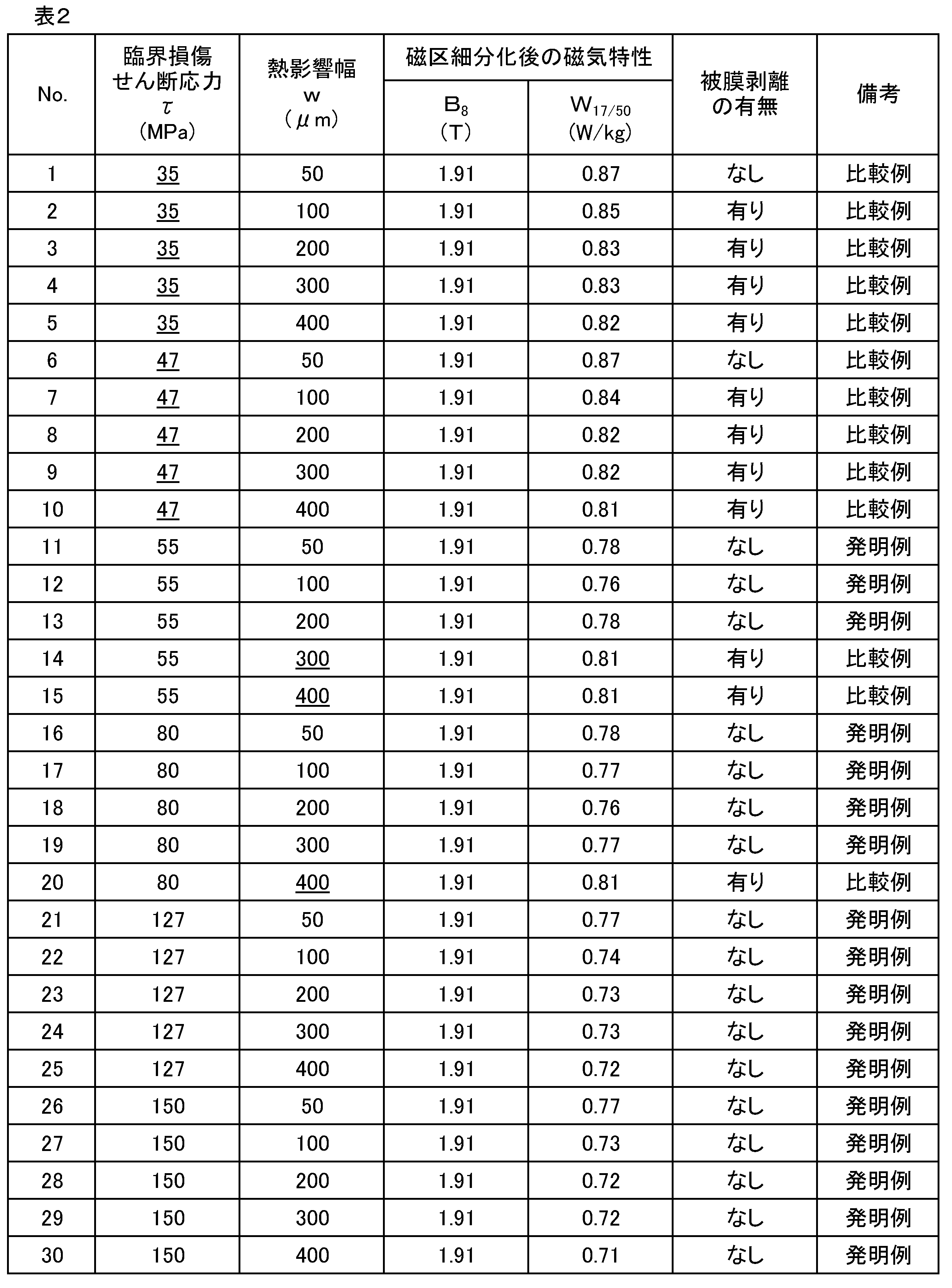
τ≧50MPa ---(1)
w≦2τ+150(μm) ---(2)
さらに、次式(3)(4)を満足する場合は、さらに良好な結果が得られた。
τ≧100MPa ---(3)
2τ+150≧w≧50(μm) ---(4)
C:0.065%、Si:3.4%およびMn:0.08%を含有する鋼を溶製し、連続鋳造法で鋼スラブとした。ついで、1410℃に加熱したのち、熱間圧延により板厚2.4mmの熱延板とし、ついで1050℃,60秒の熱延板焼鈍後、一次冷間圧延して中間板厚の1.8mmとし、1120℃,80秒の中間焼鈍後、200℃の温間圧延により最終板厚0.23mmの冷延板とした。ついで、表3に示すように雰囲気酸化度P(H2O)/P(H2)を0.02~0.6の範囲で変化させて、湿潤H2-N2雰囲気中にて820℃,50~150秒の一次再結晶焼鈍を兼ねた脱炭焼鈍を施した。
かくして得られた脱炭焼鈍板の一部を採取し、その赤外反射スペクトルからFe2SiO4(Af)とSiO2(As)のピークの比Af/Asを測定し、表面から0.5μmの深さから電解研磨により抽出される内部酸化物を5μm2の範囲で20箇所TEMで観察し、球状SiO2の平均粒径を計測した。その後、MgOを主体とし、CuO2、SnO2、MnO2、Fe3O4、Fe2O3、Cr2O3およびTiO2を0~25%の範囲で変化させて添加した焼鈍分離剤を鋼板表面に塗布し、乾燥後、950~1100℃の範囲の加熱にかかる時間を8hとした二次再結晶焼鈍と水素雰囲気下で1200℃,7hの純化処理を含む仕上げ焼鈍を施した。
さらに、先の磁気測定済の試験片に対し、レーザ光を圧延方向の間隔5mm、圧延直角方向で線状に照射する磁区細分化処理を行って、磁区細分化処理済みの方向性電磁鋼板とした。磁区細分化処理後の鋼板を、JISC2556に記載の方法で鉄損W17/50を測定し、平均値を求めた。
そして、鋼板のレーザ光照射後における、被膜の目視による外観検査を行った。
得られた結果を、表3に併記する。

Claims (4)
- セラミックス下地被膜と絶縁コーティングとを具える方向性電磁鋼板であって、該下地被膜と地鉄との間の臨界損傷せん断応力τが50MPa以上である方向性電磁鋼板。
- 非耐熱型磁区細分化領域有し、該磁区細分化領域における熱歪部の幅である熱影響幅wが50μm以上、(2τ+150)μm以下である請求項1記載の方向性電磁鋼板。
- C:0.10mass%以下、Si:2.0~4.5mass%およびMn:0.005~1.0mass%を含有する鋼素材を、熱間圧延して熱延板とし、必要に応じて熱延板焼鈍を施したのち、1回または中間焼鈍を挟む2回以上の冷間圧延して最終板厚の冷延板とし、ついで一次再結晶焼鈍を兼ねた脱炭焼鈍を施して脱炭焼鈍板としたのち、該脱炭焼鈍板の表面にMgOを主成分とする焼鈍分離剤を塗布してから、仕上げ焼鈍を施し、その後絶縁コーティング処理を施す方向性電磁鋼板の製造方法において、
上記した製造工程中、下記の条件を満足させる方向性電磁鋼板の製造方法。
記
(1)上記脱炭焼鈍板の表面内部酸化層中の酸化物を赤外反射スペクトルで評価したときFe2SiO4(Af)とSiO2(As)のピークの比Af/Asが0.4以下となる組成とすること。
(2)上記内部酸化層の表面側0.5μmから抽出した球状のシリカの直径平均が50~200nmであること。
(3)上記焼鈍分離剤中に、CuO2、SnO2、MnO2、Fe3O4、Fe2O3、Cr2O3およびTiO2のうちから選ばれる1種又は2種以上の金属酸化物を合計で2~30mass%添加すること。
(4)上記仕上げ焼鈍の加熱時に、950~1100℃間の加熱にかかる時間を10h以内とすること。 - 前記の絶縁コーティング処理後、非耐熱型磁区細分化処理を施し、その際、磁区細分化領域における熱歪部の幅である熱影響幅wを50μm以上、(2τ+150)μm以下とする請求項3記載の方向性電磁鋼板の製造方法。
Priority Applications (7)
| Application Number | Priority Date | Filing Date | Title |
|---|---|---|---|
| US15/549,742 US10988822B2 (en) | 2015-02-13 | 2016-02-12 | Grain-oriented electrical steel sheet and method for manufacturing same |
| KR1020197030793A KR102062182B1 (ko) | 2015-02-13 | 2016-02-12 | 방향성 전자 강판 및 그의 제조 방법 |
| JP2016574680A JP6344490B2 (ja) | 2015-02-13 | 2016-02-12 | 方向性電磁鋼板およびその製造方法 |
| EP16748936.8A EP3257960B1 (en) | 2015-02-13 | 2016-02-12 | Grain-oriented electrical steel sheet and method for manufacturing same |
| RU2017131867A RU2677561C1 (ru) | 2015-02-13 | 2016-02-12 | Лист из текстурированной электротехнической стали и способ его изготовления |
| CN201680009784.1A CN107208229B (zh) | 2015-02-13 | 2016-02-12 | 取向性电磁钢板及其制造方法 |
| KR1020177023335A KR20170106449A (ko) | 2015-02-13 | 2016-02-12 | 방향성 전자 강판 및 그의 제조 방법 |
Applications Claiming Priority (2)
| Application Number | Priority Date | Filing Date | Title |
|---|---|---|---|
| JP2015026385 | 2015-02-13 | ||
| JP2015-026385 | 2015-02-13 |
Publications (1)
| Publication Number | Publication Date |
|---|---|
| WO2016129291A1 true WO2016129291A1 (ja) | 2016-08-18 |
Family
ID=56614547
Family Applications (1)
| Application Number | Title | Priority Date | Filing Date |
|---|---|---|---|
| PCT/JP2016/000744 Ceased WO2016129291A1 (ja) | 2015-02-13 | 2016-02-12 | 方向性電磁鋼板およびその製造方法 |
Country Status (7)
| Country | Link |
|---|---|
| US (1) | US10988822B2 (ja) |
| EP (1) | EP3257960B1 (ja) |
| JP (1) | JP6344490B2 (ja) |
| KR (2) | KR20170106449A (ja) |
| CN (1) | CN107208229B (ja) |
| RU (1) | RU2677561C1 (ja) |
| WO (1) | WO2016129291A1 (ja) |
Cited By (4)
| Publication number | Priority date | Publication date | Assignee | Title |
|---|---|---|---|---|
| JP2019147980A (ja) * | 2018-02-26 | 2019-09-05 | 日本製鉄株式会社 | 方向性電磁鋼板の製造方法 |
| WO2020012666A1 (ja) * | 2018-07-13 | 2020-01-16 | 日本製鉄株式会社 | 方向性電磁鋼板及びその製造方法 |
| JP2022027234A (ja) * | 2020-07-31 | 2022-02-10 | Jfeスチール株式会社 | 方向性電磁鋼板 |
| US11505843B2 (en) * | 2015-12-18 | 2022-11-22 | Posco | Annealing separator for oriented electrical steel sheet, oriented electrical steel sheet, and manufacturing method of oriented electrical steel sheet |
Families Citing this family (9)
| Publication number | Priority date | Publication date | Assignee | Title |
|---|---|---|---|---|
| KR102091631B1 (ko) * | 2018-08-28 | 2020-03-20 | 주식회사 포스코 | 방향성 전기강판 및 그 자구미세화 방법 |
| RU2765976C1 (ru) * | 2018-09-27 | 2022-02-07 | ДжФЕ СТИЛ КОРПОРЕЙШН | Лист из текстурированной электротехнической стали и способ его изготовления |
| WO2020149356A1 (ja) * | 2019-01-16 | 2020-07-23 | 日本製鉄株式会社 | 方向性電磁鋼板、方向性電磁鋼板の絶縁被膜形成方法、及び方向性電磁鋼板の製造方法 |
| PL3913089T3 (pl) * | 2019-01-16 | 2024-08-05 | Nippon Steel Corporation | Blacha cienka ze stali elektrotechnicznej o ziarnach zorientowanych i sposób jej wytwarzania |
| KR102675615B1 (ko) | 2019-07-31 | 2024-06-14 | 제이에프이 스틸 가부시키가이샤 | 선상 홈 형성 방법 및 선상 홈 형성 장치 그리고 방향성 전기 강판의 제조 방법 |
| WO2021054371A1 (ja) * | 2019-09-19 | 2021-03-25 | 日本製鉄株式会社 | 方向性電磁鋼板 |
| CA3167818C (en) * | 2020-05-19 | 2023-12-12 | Jfe Steel Corporation | Grain-oriented electrical steel sheet and method of manufacturing same |
| US12486554B2 (en) | 2021-03-03 | 2025-12-02 | Jfe Steel Corporation | Method of determining final annealing conditions for grain-oriented electrical steel sheet and method of producing grain-oriented electrical steel sheet using method of determining thereof |
| KR20230095339A (ko) * | 2021-12-22 | 2023-06-29 | 주식회사 포스코 | 방향성 전기강판 및 방향성 전기강판의 제조 방법 |
Citations (6)
| Publication number | Priority date | Publication date | Assignee | Title |
|---|---|---|---|---|
| JP2004292834A (ja) * | 2003-03-25 | 2004-10-21 | Jfe Steel Kk | 被膜特性に優れる方向性電磁鋼板の製造方法 |
| JP2012012666A (ja) * | 2010-06-30 | 2012-01-19 | Jfe Steel Corp | 方向性電磁鋼板およびその製造方法 |
| JP2012214902A (ja) * | 2005-05-23 | 2012-11-08 | Nippon Steel Corp | 被膜密着性に優れる方向性電磁鋼板およびその製造方法 |
| JP2013057119A (ja) * | 2011-08-18 | 2013-03-28 | Jfe Steel Corp | 方向性電磁鋼板の製造方法 |
| WO2013046716A1 (ja) * | 2011-09-28 | 2013-04-04 | Jfeスチール株式会社 | 方向性電磁鋼板およびその製造方法 |
| JP2013072116A (ja) * | 2011-09-28 | 2013-04-22 | Jfe Steel Corp | 方向性電磁鋼板およびその製造方法 |
Family Cites Families (14)
| Publication number | Priority date | Publication date | Assignee | Title |
|---|---|---|---|---|
| JPS5518566A (en) | 1978-07-26 | 1980-02-08 | Nippon Steel Corp | Improving method for iron loss characteristic of directional electrical steel sheet |
| JPS5826409B2 (ja) | 1980-01-25 | 1983-06-02 | 新日本製鐵株式会社 | 鉄損特性にすぐれた電磁鋼板の製造方法 |
| JPS5850298B2 (ja) | 1980-01-25 | 1983-11-09 | 新日本製鐵株式会社 | 電磁鋼板の処理方法 |
| JPH0619112B2 (ja) | 1986-09-26 | 1994-03-16 | 新日本製鐵株式会社 | 電磁鋼板の鉄損値改善方法 |
| JP2654862B2 (ja) | 1990-10-27 | 1997-09-17 | 新日本製鐵株式会社 | 鉄心加工性および耐粉塵化性が優れた方向性電磁鋼板の絶縁皮膜形成方法 |
| JP2861702B2 (ja) * | 1993-01-19 | 1999-02-24 | 日本鋼管株式会社 | 加工性および耐熱性に優れた絶縁皮膜を有する方向性電磁鋼板およびその製造方法 |
| JP3361709B2 (ja) | 1997-01-24 | 2003-01-07 | 新日本製鐵株式会社 | 磁気特性の優れた方向性電磁鋼板の製造方法 |
| JP3482340B2 (ja) | 1998-03-26 | 2003-12-22 | 新日本製鐵株式会社 | 一方向性電磁鋼板とその製造方法 |
| JP3873489B2 (ja) | 1998-11-10 | 2007-01-24 | Jfeスチール株式会社 | 被膜特性および磁気特性に優れる方向性けい素鋼板の製造方法 |
| JP5098327B2 (ja) | 2005-12-28 | 2012-12-12 | Jfeスチール株式会社 | 絶縁被膜を有する電磁鋼板 |
| JP5194535B2 (ja) | 2006-07-26 | 2013-05-08 | 新日鐵住金株式会社 | 高強度無方向性電磁鋼板 |
| RU2496905C1 (ru) * | 2009-07-31 | 2013-10-27 | ДжФЕ СТИЛ КОРПОРЕЙШН | Лист электротехнической стали с ориентированными зернами |
| EP2602340B1 (en) * | 2010-08-06 | 2019-06-12 | JFE Steel Corporation | Oriented electromagnetic steel plate and production method for same |
| JP5949813B2 (ja) | 2013-03-07 | 2016-07-13 | Jfeスチール株式会社 | 方向性電磁鋼板の製造方法 |
-
2016
- 2016-02-12 KR KR1020177023335A patent/KR20170106449A/ko not_active Ceased
- 2016-02-12 US US15/549,742 patent/US10988822B2/en active Active
- 2016-02-12 JP JP2016574680A patent/JP6344490B2/ja active Active
- 2016-02-12 KR KR1020197030793A patent/KR102062182B1/ko active Active
- 2016-02-12 CN CN201680009784.1A patent/CN107208229B/zh active Active
- 2016-02-12 WO PCT/JP2016/000744 patent/WO2016129291A1/ja not_active Ceased
- 2016-02-12 EP EP16748936.8A patent/EP3257960B1/en active Active
- 2016-02-12 RU RU2017131867A patent/RU2677561C1/ru active
Patent Citations (6)
| Publication number | Priority date | Publication date | Assignee | Title |
|---|---|---|---|---|
| JP2004292834A (ja) * | 2003-03-25 | 2004-10-21 | Jfe Steel Kk | 被膜特性に優れる方向性電磁鋼板の製造方法 |
| JP2012214902A (ja) * | 2005-05-23 | 2012-11-08 | Nippon Steel Corp | 被膜密着性に優れる方向性電磁鋼板およびその製造方法 |
| JP2012012666A (ja) * | 2010-06-30 | 2012-01-19 | Jfe Steel Corp | 方向性電磁鋼板およびその製造方法 |
| JP2013057119A (ja) * | 2011-08-18 | 2013-03-28 | Jfe Steel Corp | 方向性電磁鋼板の製造方法 |
| WO2013046716A1 (ja) * | 2011-09-28 | 2013-04-04 | Jfeスチール株式会社 | 方向性電磁鋼板およびその製造方法 |
| JP2013072116A (ja) * | 2011-09-28 | 2013-04-22 | Jfe Steel Corp | 方向性電磁鋼板およびその製造方法 |
Cited By (8)
| Publication number | Priority date | Publication date | Assignee | Title |
|---|---|---|---|---|
| US11505843B2 (en) * | 2015-12-18 | 2022-11-22 | Posco | Annealing separator for oriented electrical steel sheet, oriented electrical steel sheet, and manufacturing method of oriented electrical steel sheet |
| JP2019147980A (ja) * | 2018-02-26 | 2019-09-05 | 日本製鉄株式会社 | 方向性電磁鋼板の製造方法 |
| JP7031364B2 (ja) | 2018-02-26 | 2022-03-08 | 日本製鉄株式会社 | 方向性電磁鋼板の製造方法 |
| WO2020012666A1 (ja) * | 2018-07-13 | 2020-01-16 | 日本製鉄株式会社 | 方向性電磁鋼板及びその製造方法 |
| JPWO2020012666A1 (ja) * | 2018-07-13 | 2021-08-05 | 日本製鉄株式会社 | 方向性電磁鋼板及びその製造方法 |
| RU2766228C1 (ru) * | 2018-07-13 | 2022-02-10 | Ниппон Стил Корпорейшн | Лист анизотропной электротехнической стали и способ его производства |
| JP2022027234A (ja) * | 2020-07-31 | 2022-02-10 | Jfeスチール株式会社 | 方向性電磁鋼板 |
| JP7331800B2 (ja) | 2020-07-31 | 2023-08-23 | Jfeスチール株式会社 | 方向性電磁鋼板 |
Also Published As
| Publication number | Publication date |
|---|---|
| CN107208229A (zh) | 2017-09-26 |
| KR102062182B1 (ko) | 2020-01-03 |
| CN107208229B (zh) | 2019-05-21 |
| RU2677561C1 (ru) | 2019-01-17 |
| JP6344490B2 (ja) | 2018-06-20 |
| EP3257960B1 (en) | 2020-11-04 |
| KR20190121416A (ko) | 2019-10-25 |
| US20180030559A1 (en) | 2018-02-01 |
| EP3257960A1 (en) | 2017-12-20 |
| US10988822B2 (en) | 2021-04-27 |
| KR20170106449A (ko) | 2017-09-20 |
| JPWO2016129291A1 (ja) | 2017-06-22 |
| EP3257960A4 (en) | 2018-01-03 |
Similar Documents
| Publication | Publication Date | Title |
|---|---|---|
| JP6344490B2 (ja) | 方向性電磁鋼板およびその製造方法 | |
| KR101620763B1 (ko) | 방향성 전기 강판 및 그 제조 방법 | |
| RU2595190C1 (ru) | Способ изготовления листа электротехнической текстурированной стали | |
| JP6168173B2 (ja) | 方向性電磁鋼板とその製造方法 | |
| RU2580776C1 (ru) | Способ изготовления листа из текстурированной электротехнической стали | |
| KR101921401B1 (ko) | 방향성 전기 강판의 제조 방법 | |
| WO2017006955A1 (ja) | 方向性電磁鋼板とその製造方法 | |
| WO2011105054A1 (ja) | 方向性電磁鋼板の製造方法 | |
| JP6825681B2 (ja) | 方向性電磁鋼板およびその製造方法 | |
| JP6436316B2 (ja) | 方向性電磁鋼板の製造方法 | |
| KR101973305B1 (ko) | 방향성 전자 강판 및 그 제조 방법 | |
| KR20160138253A (ko) | 방향성 전기 강판의 제조 방법 | |
| JP5871137B2 (ja) | 方向性電磁鋼板 | |
| JP2008285758A (ja) | 一方向性電磁鋼板 | |
| WO2016159349A1 (ja) | 一方向性電磁鋼板の製造方法 | |
| JP5839172B2 (ja) | 方向性電磁鋼板の製造方法 | |
| JP5287641B2 (ja) | 方向性電磁鋼板の製造方法 | |
| JP7099648B1 (ja) | 方向性電磁鋼板およびその製造方法 | |
| JP7329049B2 (ja) | 電磁鋼板およびその製造方法 | |
| JP2006274405A (ja) | 高磁束密度方向性電磁鋼板の製造方法 | |
| JP4276547B2 (ja) | 高磁場鉄損と被膜特性に優れる超高磁束密度一方向性電磁鋼板 | |
| JP5846390B2 (ja) | 方向性電磁鋼板の製造方法 | |
| JPWO2021085421A1 (ja) | 方向性電磁鋼板とその製造方法 | |
| JP2007262436A (ja) | 方向性電磁鋼板の製造方法 | |
| JP2002194433A (ja) | 被膜特性および磁気特性に優れた方向性電磁鋼板の製造方法 |
Legal Events
| Date | Code | Title | Description |
|---|---|---|---|
| 121 | Ep: the epo has been informed by wipo that ep was designated in this application |
Ref document number: 16748936 Country of ref document: EP Kind code of ref document: A1 |
|
| ENP | Entry into the national phase |
Ref document number: 2016574680 Country of ref document: JP Kind code of ref document: A |
|
| REEP | Request for entry into the european phase |
Ref document number: 2016748936 Country of ref document: EP |
|
| NENP | Non-entry into the national phase |
Ref country code: DE |
|
| ENP | Entry into the national phase |
Ref document number: 20177023335 Country of ref document: KR Kind code of ref document: A |
|
| ENP | Entry into the national phase |
Ref document number: 2017131867 Country of ref document: RU Kind code of ref document: A |