WO2016129900A1 - Procédé et appareil pour transmettre-recevoir un canal de diffusion physique dans un système d'accès sans fil prenant en charge une communication de type machine - Google Patents
Procédé et appareil pour transmettre-recevoir un canal de diffusion physique dans un système d'accès sans fil prenant en charge une communication de type machine Download PDFInfo
- Publication number
- WO2016129900A1 WO2016129900A1 PCT/KR2016/001324 KR2016001324W WO2016129900A1 WO 2016129900 A1 WO2016129900 A1 WO 2016129900A1 KR 2016001324 W KR2016001324 W KR 2016001324W WO 2016129900 A1 WO2016129900 A1 WO 2016129900A1
- Authority
- WO
- WIPO (PCT)
- Prior art keywords
- pbch
- subframe
- mtc
- csi
- transmitted
- Prior art date
- Legal status (The legal status is an assumption and is not a legal conclusion. Google has not performed a legal analysis and makes no representation as to the accuracy of the status listed.)
- Ceased
Links
Images




Classifications
-
- H—ELECTRICITY
- H04—ELECTRIC COMMUNICATION TECHNIQUE
- H04L—TRANSMISSION OF DIGITAL INFORMATION, e.g. TELEGRAPHIC COMMUNICATION
- H04L5/00—Arrangements affording multiple use of the transmission path
- H04L5/003—Arrangements for allocating sub-channels of the transmission path
- H04L5/0053—Allocation of signalling, i.e. of overhead other than pilot signals
-
- H—ELECTRICITY
- H04—ELECTRIC COMMUNICATION TECHNIQUE
- H04B—TRANSMISSION
- H04B7/00—Radio transmission systems, i.e. using radiation field
- H04B7/24—Radio transmission systems, i.e. using radiation field for communication between two or more posts
- H04B7/26—Radio transmission systems, i.e. using radiation field for communication between two or more posts at least one of which is mobile
- H04B7/2603—Arrangements for wireless physical layer control
-
- H—ELECTRICITY
- H04—ELECTRIC COMMUNICATION TECHNIQUE
- H04B—TRANSMISSION
- H04B7/00—Radio transmission systems, i.e. using radiation field
- H04B7/24—Radio transmission systems, i.e. using radiation field for communication between two or more posts
- H04B7/26—Radio transmission systems, i.e. using radiation field for communication between two or more posts at least one of which is mobile
- H04B7/2612—Arrangements for wireless medium access control, e.g. by allocating physical layer transmission capacity
-
- H—ELECTRICITY
- H04—ELECTRIC COMMUNICATION TECHNIQUE
- H04W—WIRELESS COMMUNICATION NETWORKS
- H04W4/00—Services specially adapted for wireless communication networks; Facilities therefor
- H04W4/30—Services specially adapted for particular environments, situations or purposes
- H04W4/38—Services specially adapted for particular environments, situations or purposes for collecting sensor information
-
- H—ELECTRICITY
- H04—ELECTRIC COMMUNICATION TECHNIQUE
- H04B—TRANSMISSION
- H04B7/00—Radio transmission systems, i.e. using radiation field
- H04B7/02—Diversity systems; Multi-antenna system, i.e. transmission or reception using multiple antennas
- H04B7/04—Diversity systems; Multi-antenna system, i.e. transmission or reception using multiple antennas using two or more spaced independent antennas
- H04B7/06—Diversity systems; Multi-antenna system, i.e. transmission or reception using multiple antennas using two or more spaced independent antennas at the transmitting station
- H04B7/0613—Diversity systems; Multi-antenna system, i.e. transmission or reception using multiple antennas using two or more spaced independent antennas at the transmitting station using simultaneous transmission
- H04B7/0615—Diversity systems; Multi-antenna system, i.e. transmission or reception using multiple antennas using two or more spaced independent antennas at the transmitting station using simultaneous transmission of weighted versions of same signal
- H04B7/0619—Diversity systems; Multi-antenna system, i.e. transmission or reception using multiple antennas using two or more spaced independent antennas at the transmitting station using simultaneous transmission of weighted versions of same signal using feedback from receiving side
- H04B7/0621—Feedback content
- H04B7/0626—Channel coefficients, e.g. channel state information [CSI]
-
- H—ELECTRICITY
- H04—ELECTRIC COMMUNICATION TECHNIQUE
- H04L—TRANSMISSION OF DIGITAL INFORMATION, e.g. TELEGRAPHIC COMMUNICATION
- H04L5/00—Arrangements affording multiple use of the transmission path
- H04L5/003—Arrangements for allocating sub-channels of the transmission path
- H04L5/0048—Allocation of pilot signals, i.e. of signals known to the receiver
-
- H—ELECTRICITY
- H04—ELECTRIC COMMUNICATION TECHNIQUE
- H04W—WIRELESS COMMUNICATION NETWORKS
- H04W4/00—Services specially adapted for wireless communication networks; Facilities therefor
- H04W4/02—Services making use of location information
- H04W4/021—Services related to particular areas, e.g. point of interest [POI] services, venue services or geofences
Definitions
- the present invention relates to a wireless access system supporting Machine Type Communication (MTC), and more particularly, to a method and apparatus for repeatedly transmitting and receiving a physical broadcast channel (PBCH) for an MTC terminal.
- MTC Machine Type Communication
- PBCH physical broadcast channel
- Wireless access systems are widely deployed to provide various kinds of communication services such as voice and data.
- a wireless access system is a multiple access system capable of supporting communication with multiple users by sharing available system resources (bandwidth, transmission power, etc.).
- multiple access systems include code division multiple access (CDMA) systems, frequency division multiple access (FDMA) systems, time division multiple access (TDMA) systems, orthogonal frequency division multiple access (OFDMA) systems, and single carrier frequency (SC-FDMA). division multiple access) system.
- CDMA code division multiple access
- FDMA frequency division multiple access
- TDMA time division multiple access
- OFDMA orthogonal frequency division multiple access
- SC-FDMA single carrier frequency division multiple access
- An object of the present invention is to provide a method for configuring a PBCH for the MTC terminal.
- Another object of the present invention is to provide a method for repeatedly transmitting control information transmitted through a PBCH for an MTC terminal.
- Another object of the present invention is to provide an apparatus supporting these methods.
- the present invention relates to a radio access system supporting machine type communication (MTC), and more particularly, to a method of repeatedly transmitting a physical broadcast channel (PBCH) for an MTC and to provide apparatuses for supporting the same.
- MTC radio access system supporting machine type communication
- PBCH physical broadcast channel
- a method of repeatedly transmitting a physical broadcast channel (PBCH) for an MTC terminal in a wireless access system supporting machine type communication includes: a first PBCH through a legacy PBCH transmission region of a first subframe; And transmitting the second PBCH repeatedly in the first subframe and transmitting the third PBCH repeatedly in the second subframe.
- the control region of the first subframe and the second subframe may be configured such that repetitive transmission of the second PBCH and the third PBCH is not performed.
- a base station for repeatedly transmitting a physical broadcast channel (PBCH) for an MTC terminal in a wireless access system supporting machine type communication may include a transmitter and a processor for supporting repeated transmission of the PBCH.
- the processor controls the transmitter to transmit the first PBCH through the legacy PBCH transmission region of the first subframe; Repeatedly transmitting the second PBCH in the first subframe; It may be configured to repeatedly transmit the third PBCH in the second subframe.
- the control region of the first subframe and the second subframe may be configured such that repetitive transmission of the second PBCH and the third PBCH is not performed.
- the control region may be allocated from the first symbol to the third or fourth symbol of the first slot of the first subframe and the second subframe.
- the third PBCH may not be allocated to the resource element RE to which the reference signal RS is allocated in the second subframe.
- RS is a channel state information reference signal (CSI-RS), and RE is mapped to a CSI-RS configuration commonly used in a frequency division multiplexing scheme (FDD) and a time division multiplexing scheme (TDD) among CSI-RS configurations. It may be an RE to which the CSI-RS is allocated.
- the RE may be allocated to the sixth and seventh symbols in the first slot and the third and fourth or the sixth and seventh symbols in the second slot.
- the second PBCH may be transmitted through the MTC transmission region for the MTC terminal in the first subframe
- the third PBCH may be transmitted through the MTC transmission region for the MTC terminal in the second subframe.
- the first subframe and the second subframe may be consecutive subframes.
- the PBCH can be reliably transmitted to MTC terminals located in poor environments.
- a phase difference value is constant so that the base station and / or the MTC terminal can efficiently and accurately perform frequency tracking and / or frequency offset estimation.
- 1 is a diagram illustrating a physical channel and a signal transmission method using the same.
- FIG. 2 is a diagram illustrating an example of a structure of a radio frame.
- 3 is a diagram illustrating a resource grid for a downlink slot.
- FIG. 4 is a diagram illustrating an example of a structure of an uplink subframe.
- 5 is a diagram illustrating an example of a structure of a downlink subframe.
- FIG. 6 illustrates a subframe structure of an LTE-A system according to cross carrier scheduling used in embodiments of the present invention.
- FIG. 7 is a diagram illustrating an example of an initial access procedure used in an LTE / LTE-A system.
- FIG. 8 is a diagram illustrating one method of transmitting a broadcast channel signal.
- FIG. 9 is a conceptual diagram of a CoMP system operating based on a CA environment.
- FIG. 10 is a diagram illustrating an example of a subframe to which a cell specific reference signal (CRS) is allocated, which can be used in embodiments of the present invention.
- CRS cell specific reference signal
- FIG. 11 is a diagram illustrating an example of subframes in which CSI-RSs that can be used in embodiments of the present invention are allocated according to the number of antenna ports.
- FIG. 12 is a diagram illustrating an example in which legacy PDCCH, PDSCH, and E-PDCCH used in an LTE / LTE-A system are multiplexed.
- FIG. 13 is a diagram for describing a method of repeatedly transmitting a PBCH to an MTC terminal by a base station.
- FIG. 14 is a diagram for describing a method of repeatedly transmitting an MTC PBCH to an MTC terminal.
- FIG. 15 is a means in which the methods described in FIGS. 1 to 14 may be implemented.
- Embodiments of the present invention described in detail below provide methods and apparatuses using heterogeneous network signals to measure the position of a terminal.
- each component or feature may be considered to be optional unless otherwise stated.
- Each component or feature may be embodied in a form that is not combined with other components or features.
- some components and / or features may be combined to form an embodiment of the present invention.
- the order of the operations described in the embodiments of the present invention may be changed. Some components or features of one embodiment may be included in another embodiment or may be replaced with corresponding components or features of another embodiment.
- the base station is meant as a terminal node of a network that directly communicates with a mobile station.
- the specific operation described as performed by the base station in this document may be performed by an upper node of the base station in some cases.
- various operations performed for communication with a mobile station in a network consisting of a plurality of network nodes including a base station may be performed by the base station or network nodes other than the base station.
- the 'base station' may be replaced by terms such as a fixed station, a Node B, an eNode B (eNB), an advanced base station (ABS), or an access point.
- a terminal may be a user equipment (UE), a mobile station (MS), a subscriber station (SS), or a mobile subscriber station (MSS). It may be replaced with terms such as a mobile terminal or an advanced mobile station (AMS).
- UE user equipment
- MS mobile station
- SS subscriber station
- MSS mobile subscriber station
- AMS advanced mobile station
- the transmitting end refers to a fixed and / or mobile node that provides a data service or a voice service
- the receiving end refers to a fixed and / or mobile node that receives a data service or a voice service. Therefore, in uplink, a mobile station may be a transmitting end and a base station may be a receiving end. Similarly, in downlink, a mobile station may be a receiving end and a base station may be a transmitting end.
- Embodiments of the present invention may be supported by standard documents disclosed in at least one of the IEEE 802.xx system, the 3rd Generation Partnership Project (3GPP) system, the 3GPP LTE system, and the 3GPP2 system, which are wireless access systems, and in particular, the present invention.
- Embodiments of the may be supported by 3GPP TS 36.211, 3GPP TS 36.212, 3GPP TS 36.213, 3GPP TS 36.321 and 3GPP TS 36.331 documents. That is, obvious steps or portions not described among the embodiments of the present invention may be described with reference to the above documents.
- all terms disclosed in the present document can be described by the above standard document.
- 3GPP LTE / LTE-A system will be described as an example of a wireless access system in which embodiments of the present invention can be used.
- CDMA code division multiple access
- FDMA frequency division multiple access
- TDMA time division multiple access
- OFDMA orthogonal frequency division multiple access
- SC-FDMA single carrier frequency division multiple access
- CDMA may be implemented with a radio technology such as Universal Terrestrial Radio Access (UTRA) or CDMA2000.
- TDMA may be implemented with wireless technologies such as Global System for Mobile communications (GSM) / General Packet Radio Service (GPRS) / Enhanced Data Rates for GSM Evolution (EDGE).
- GSM Global System for Mobile communications
- GPRS General Packet Radio Service
- EDGE Enhanced Data Rates for GSM Evolution
- OFDMA may be implemented in a wireless technology such as IEEE 802.11 (Wi-Fi), IEEE 802.16 (WiMAX), IEEE 802-20, Evolved UTRA (E-UTRA).
- UTRA is part of the Universal Mobile Telecommunications System (UMTS).
- 3GPP Long Term Evolution (LTE) is part of an Evolved UMTS (E-UMTS) using E-UTRA, and employs OFDMA in downlink and SC-FDMA in uplink.
- LTE-A (Advanced) system is an improved system of the 3GPP LTE system.
- embodiments of the present invention will be described based on the 3GPP LTE / LTE-A system, but can also be applied to IEEE 802.16e / m system and the like.
- a terminal receives information from a base station through downlink (DL) and transmits information to the base station through uplink (UL).
- the information transmitted and received by the base station and the terminal includes general data information and various control information, and various physical channels exist according to the type / use of the information they transmit and receive.
- FIG. 1 is a diagram for explaining physical channels that can be used in embodiments of the present invention and a signal transmission method using the same.
- the initial cell search operation such as synchronizing with the base station is performed in step S11.
- the UE receives a Primary Synchronization Channel (P-SCH) and a Secondary Synchronization Channel (S-SCH) from the base station, synchronizes with the base station, and obtains information such as a cell ID.
- P-SCH Primary Synchronization Channel
- S-SCH Secondary Synchronization Channel
- the terminal may receive a physical broadcast channel (PBCH) signal from the base station to obtain broadcast information in a cell.
- PBCH physical broadcast channel
- the terminal may receive a downlink reference signal (DL RS) in the initial cell search step to confirm the downlink channel state.
- DL RS downlink reference signal
- the UE After completing the initial cell search, the UE receives a physical downlink control channel (PDCCH) and a physical downlink control channel (PDSCH) according to the physical downlink control channel information in step S12. Specific system information can be obtained.
- PDCCH physical downlink control channel
- PDSCH physical downlink control channel
- the terminal may perform a random access procedure as in steps S13 to S16 to complete the access to the base station.
- the UE transmits a preamble through a physical random access channel (PRACH) (S13), a response message to the preamble through a physical downlink control channel and a corresponding physical downlink shared channel. Can be received (S14).
- PRACH physical random access channel
- the UE may perform contention resolution such as transmitting an additional physical random access channel signal (S15) and receiving a physical downlink control channel signal and a corresponding physical downlink shared channel signal (S16). Procedure).
- the UE After performing the above-described procedure, the UE subsequently receives a physical downlink control channel signal and / or a physical downlink shared channel signal (S17) and a physical uplink shared channel (PUSCH) as a general uplink / downlink signal transmission procedure.
- a transmission (Uplink Shared Channel) signal and / or a Physical Uplink Control Channel (PUCCH) signal may be transmitted (S18).
- UCI uplink control information
- HARQ-ACK / NACK Hybrid Automatic Repeat and reQuest Acknowledgement / Negative-ACK
- SR Scheduling Request
- CQI Channel Quality Indication
- PMI Precoding Matrix Indication
- RI Rank Indication
- UCI is generally transmitted periodically through the PUCCH, but may be transmitted through the PUSCH when control information and traffic data should be transmitted at the same time.
- the UCI may be aperiodically transmitted through the PUSCH by the request / instruction of the network.
- FIG. 2 shows a structure of a radio frame used in embodiments of the present invention.
- the type 1 frame structure can be applied to both full duplex Frequency Division Duplex (FDD) systems and half duplex FDD systems.
- FDD Frequency Division Duplex
- One subframe is defined as two consecutive slots, and the i-th subframe includes slots corresponding to 2i and 2i + 1. That is, a radio frame consists of 10 subframes.
- the time taken to transmit one subframe is called a transmission time interval (TTI).
- the slot includes a plurality of OFDM symbols or SC-FDMA symbols in the time domain and a plurality of resource blocks in the frequency domain.
- One slot includes a plurality of orthogonal frequency division multiplexing (OFDM) symbols in the time domain. Since 3GPP LTE uses OFDMA in downlink, the OFDM symbol is for representing one symbol period. The OFDM symbol may be referred to as one SC-FDMA symbol or symbol period.
- a resource block is a resource allocation unit and includes a plurality of consecutive subcarriers in one slot.
- 10 subframes may be used simultaneously for downlink transmission and uplink transmission during each 10ms period. At this time, uplink and downlink transmission are separated in the frequency domain.
- the terminal cannot transmit and receive at the same time.
- the structure of the radio frame described above is just one example, and the number of subframes included in the radio frame, the number of slots included in the subframe, and the number of OFDM symbols included in the slot may be variously changed.
- Type 2 frame structure is applied to the TDD system.
- the type 2 frame includes a special subframe consisting of three fields: a downlink pilot time slot (DwPTS), a guard period (GP), and an uplink pilot time slot (UpPTS).
- DwPTS downlink pilot time slot
- GP guard period
- UpPTS uplink pilot time slot
- the DwPTS is used for initial cell search, synchronization or channel estimation in the terminal.
- UpPTS is used for channel estimation at the base station and synchronization of uplink transmission of the terminal.
- the guard period is a period for removing interference generated in the uplink due to the multipath delay of the downlink signal between the uplink and the downlink.
- Table 1 below shows the structure of the special frame (length of DwPTS / GP / UpPTS).
- FIG. 3 is a diagram illustrating a resource grid for a downlink slot that can be used in embodiments of the present invention.
- one downlink slot includes a plurality of OFDM symbols in the time domain.
- one downlink slot includes seven OFDM symbols, and one resource block includes 12 subcarriers in a frequency domain, but is not limited thereto.
- Each element on the resource grid is a resource element, and one resource block includes 12 ⁇ 7 resource elements.
- the number N DL of resource blocks included in the downlink slot depends on the downlink transmission bandwidth.
- the structure of the uplink slot may be the same as the structure of the downlink slot.
- FIG. 4 shows a structure of an uplink subframe that can be used in embodiments of the present invention.
- an uplink subframe may be divided into a control region and a data region in the frequency domain.
- the control region is allocated a PUCCH carrying uplink control information.
- a PUSCH carrying user data is allocated.
- one UE does not simultaneously transmit a PUCCH and a PUSCH.
- the PUCCH for one UE is allocated an RB pair in a subframe. RBs belonging to the RB pair occupy different subcarriers in each of the two slots.
- the RB pair assigned to this PUCCH is said to be frequency hopping at the slot boundary.
- FIG. 5 shows a structure of a downlink subframe that can be used in embodiments of the present invention.
- up to three OFDM symbols from the OFDM symbol index 0 in the first slot in the subframe are control regions to which control channels are allocated, and the remaining OFDM symbols are data regions to which the PDSCH is allocated. to be.
- a downlink control channel used in 3GPP LTE includes a Physical Control Format Indicator Channel (PCFICH), a PDCCH, and a Physical Hybrid-ARQ Indicator Channel (PHICH).
- PCFICH Physical Control Format Indicator Channel
- PDCCH Physical Hybrid-ARQ Indicator Channel
- PHICH Physical Hybrid-ARQ Indicator Channel
- the PCFICH is transmitted in the first OFDM symbol of a subframe and carries information about the number of OFDM symbols (ie, the size of the control region) used for transmission of control channels within the subframe.
- the PHICH is a response channel for the uplink and carries an ACK (Acknowledgement) / NACK (Negative-Acknowledgement) signal for a hybrid automatic repeat request (HARQ).
- Control information transmitted through the PDCCH is called downlink control information (DCI).
- the downlink control information includes uplink resource allocation information, downlink resource allocation information or an uplink transmission (Tx) power control command for a certain terminal group.
- CA Carrier Aggregation
- LTE system 3rd Generation Partnership Project Long Term Evolution (Rel-8 or Rel-9) system
- MCM multi-carrier modulation
- CC component carrier
- Multi-Carrier Modulation is used.
- LTE-A system a method such as Carrier Aggregation (CA) may be used in which one or more component carriers are combined to support a wider system bandwidth than the LTE system.
- CA Carrier Aggregation
- Carrier aggregation may be replaced with the words carrier aggregation, carrier matching, multi-component carrier environment (Multi-CC) or multicarrier environment.
- the multi-carrier means the aggregation of carriers (or carrier aggregation), wherein the aggregation of carriers means not only merging between contiguous carriers but also merging between non-contiguous carriers.
- the number of component carriers aggregated between downlink and uplink may be set differently.
- the case where the number of downlink component carriers (hereinafter referred to as 'DL CC') and the number of uplink component carriers (hereinafter referred to as 'UL CC') is the same is called symmetric merging. This is called asymmetric merging.
- Such carrier aggregation may be used interchangeably with terms such as carrier aggregation, bandwidth aggregation, spectrum aggregation, and the like.
- Carrier aggregation in which two or more component carriers are combined, aims to support up to 100 MHz bandwidth in an LTE-A system.
- the bandwidth of the combining carrier may be limited to the bandwidth used by the existing system to maintain backward compatibility with the existing IMT system.
- the existing 3GPP LTE system supports ⁇ 1.4, 3, 5, 10, 15, 20 ⁇ MHz bandwidth
- the 3GPP LTE-advanced system i.e., LTE-A
- LTE-A 3GPP LTE-advanced system
- the carrier aggregation system used in the present invention may support carrier aggregation by defining a new bandwidth regardless of the bandwidth used in the existing system.
- the carrier aggregation may be divided into an intra-band CA and an inter-band CA.
- Intra-band carrier merging means that a plurality of DL CCs and / or UL CCs are located adjacent to or in proximity to frequency. In other words, it may mean that the carrier frequencies of the DL CCs and / or UL CCs are located in the same band.
- an environment far from the frequency domain may be referred to as an inter-band CA.
- the terminal may use a plurality of radio frequency (RF) terminals to perform communication in a carrier aggregation environment.
- RF radio frequency
- the LTE-A system uses the concept of a cell to manage radio resources.
- the carrier aggregation environment described above may be referred to as a multiple cell environment.
- a cell is defined as a combination of a downlink resource (DL CC) and an uplink resource (UL CC), but the uplink resource is not an essential element. Accordingly, the cell may be configured with only downlink resources or with downlink resources and uplink resources.
- a specific UE when a specific UE has only one configured serving cell, it may have one DL CC and one UL CC. However, when a specific terminal has two or more configured serving cells, it may have as many DL CCs as the number of cells and the number of UL CCs may be the same or smaller than that. Alternatively, the DL CC and the UL CC may be configured on the contrary. That is, when a specific UE has a plurality of configured serving cells, a carrier aggregation environment in which a UL CC has more than the number of DL CCs may be supported.
- Carrier coupling may also be understood as the merging of two or more cells, each having a different carrier frequency (center frequency of the cell).
- the term 'cell' in terms of carrier combining is described in terms of frequency, and should be distinguished from 'cell' as a geographical area covered by a commonly used base station.
- intra-band carrier merging is referred to as an intra-band multi-cell
- inter-band carrier merging is referred to as an inter-band multi-cell.
- the cell used in the LTE-A system includes a primary cell (P cell) and a secondary cell (S cell).
- the PCell and the SCell may be used as serving cells.
- the UE that is in the RRC_CONNECTED state but the carrier aggregation is not configured or does not support the carrier aggregation, there is only one serving cell composed of the PCell.
- one or more serving cells may exist, and the entire serving cell includes a PCell and one or more SCells.
- Serving cells may be configured through an RRC parameter.
- PhyS cell Id is a cell's physical layer identifier and has an integer value from 0 to 503.
- SCell Index is a short identifier used to identify SCell and has an integer value from 1 to 7.
- ServCellIndex is a short identifier used to identify a serving cell (P cell or S cell) and has an integer value from 0 to 7. A value of 0 is applied to the P cell, and the S cell Index is given in advance to apply to the S cell. That is, a cell having the smallest cell ID (or cell index) in ServCellIndex becomes a P cell.
- P cell refers to a cell operating on a primary frequency (or primary CC).
- the UE may be used to perform an initial connection establishment process or to perform a connection re-establishment process, and may also refer to a cell indicated in a handover process.
- the P cell refers to a cell serving as a center of control-related communication among serving cells configured in a carrier aggregation environment. That is, the terminal may receive and transmit a PUCCH only in its own Pcell, and may use only the Pcell to acquire system information or change a monitoring procedure.
- E-UTRAN Evolved Universal Terrestrial Radio Access
- RRC ConnectionReconfigutaion message of a higher layer including mobility control information to a UE supporting a carrier aggregation environment. It may be.
- the S cell may refer to a cell operating on a secondary frequency (or, secondary CC). Only one PCell may be allocated to a specific UE, and one or more SCells may be allocated.
- the SCell is configurable after the RRC connection is established and may be used to provide additional radio resources.
- PUCCH does not exist in the remaining cells excluding the P cell, that is, the S cell, among the serving cells configured in the carrier aggregation environment.
- the E-UTRAN may provide all system information related to the operation of the related cell in the RRC_CONNECTED state through a dedicated signal.
- the change of the system information may be controlled by the release and addition of the related SCell, and at this time, an RRC connection reconfigutaion message of a higher layer may be used.
- the E-UTRAN may transmit specific signaling having different parameters for each terminal, rather than broadcasting in the related SCell.
- the E-UTRAN may configure a network including one or more Scells in addition to the Pcells initially configured in the connection establishment process.
- the Pcell and the SCell may operate as respective component carriers.
- the primary component carrier (PCC) may be used in the same sense as the PCell
- the secondary component carrier (SCC) may be used in the same sense as the SCell.
- Cross carrier scheduling may be referred to as Cross Component Carrier Scheduling or Cross Cell Scheduling.
- Self-scheduling is transmitted through a DL CC in which a PDCCH (DL Grant) and a PDSCH are transmitted in the same DL CC, or a PUSCH transmitted according to a PDCCH (UL Grant) transmitted in a DL CC is linked to a DL CC in which a UL Grant has been received. It means to be.
- a DL CC in which a PDCCH (DL Grant) and a PDSCH are transmitted to different DL CCs or a UL CC in which a PUSCH transmitted according to a PDCCH (UL Grant) transmitted in a DL CC is linked to a DL CC having received an UL grant This means that it is transmitted through other UL CC.
- Whether to perform cross-carrier scheduling may be activated or deactivated UE-specifically and may be known for each UE semi-statically through higher layer signaling (eg, RRC signaling).
- higher layer signaling eg, RRC signaling
- a carrier indicator field (CIF: Carrier Indicator Field) indicating a PDSCH / PUSCH indicated by the corresponding PDCCH is transmitted to the PDCCH.
- the PDCCH may allocate PDSCH resource or PUSCH resource to one of a plurality of component carriers using CIF. That is, when the PDCCH on the DL CC allocates PDSCH or PUSCH resources to one of the multi-aggregated DL / UL CC, CIF is set.
- the DCI format of LTE Release-8 may be extended according to CIF.
- the set CIF may be fixed as a 3 bit field or the position of the set CIF may be fixed regardless of the DCI format size.
- the PDCCH structure (same coding and resource mapping based on the same CCE) of LTE Release-8 may be reused.
- the PDCCH on the DL CC allocates PDSCH resources on the same DL CC or PUSCH resources on a single linked UL CC, CIF is not configured.
- the same PDCCH structure (same coding and resource mapping based on the same CCE) and DCI format as in LTE Release-8 may be used.
- the UE When cross carrier scheduling is possible, the UE needs to monitor the PDCCHs for the plurality of DCIs in the control region of the monitoring CC according to the transmission mode and / or bandwidth for each CC. Therefore, it is necessary to configure the search space and PDCCH monitoring that can support this.
- the terminal DL CC set represents a set of DL CCs scheduled for the terminal to receive a PDSCH
- the terminal UL CC set represents a set of UL CCs scheduled for the terminal to transmit a PUSCH.
- the PDCCH monitoring set represents a set of at least one DL CC that performs PDCCH monitoring.
- the PDCCH monitoring set may be the same as the terminal DL CC set or may be a subset of the terminal DL CC set.
- the PDCCH monitoring set may include at least one of DL CCs in the terminal DL CC set. Alternatively, the PDCCH monitoring set may be defined separately regardless of the UE DL CC set.
- the DL CC included in the PDCCH monitoring set may be configured to always enable self-scheduling for the linked UL CC.
- the UE DL CC set, the UE UL CC set, and the PDCCH monitoring set may be configured UE-specifically, UE group-specifically, or cell-specifically.
- cross-carrier scheduling When cross-carrier scheduling is deactivated, it means that the PDCCH monitoring set is always the same as the UE DL CC set. In this case, an indication such as separate signaling for the PDCCH monitoring set is not necessary.
- a PDCCH monitoring set is defined in the terminal DL CC set. That is, in order to schedule PDSCH or PUSCH for the UE, the base station transmits the PDCCH through only the PDCCH monitoring set.
- FIG. 6 illustrates a subframe structure of an LTE-A system according to cross carrier scheduling used in embodiments of the present invention.
- DL CC 'A' represents a case in which a PDCCH monitoring DL CC is configured.
- each DL CC may transmit a PDCCH for scheduling its PDSCH without CIF.
- the CIF is used through higher layer signaling, only one DL CC 'A' may transmit a PDCCH for scheduling its PDSCH or PDSCH of another CC using the CIF.
- DL CCs 'B' and 'C' that are not configured as PDCCH monitoring DL CCs do not transmit the PDCCH.
- the initial access procedure may consist of a cell search process, a system information acquisition process, and a random access procedure.
- FIG. 7 is a diagram illustrating an example of an initial access procedure used in an LTE / LTE-A system.
- the terminal may obtain downlink synchronization information by receiving synchronization signals (for example, primary synchronization signal (PSS) and secondary synchronization signal (SSS)) transmitted from the base station.
- synchronization signals for example, primary synchronization signal (PSS) and secondary synchronization signal (SSS)
- PSS primary synchronization signal
- SSS secondary synchronization signal
- the synchronization signals are transmitted twice every frame (10 ms units). That is, the synchronization signals are transmitted every 5 ms (S710).
- the downlink synchronization information obtained in step S710 may include a physical cell identifier (PCID), downlink time and frequency synchronization, and cyclic prefix (CP) length information.
- PCID physical cell identifier
- CP cyclic prefix
- the terminal receives a PBCH signal transmitted through a physical broadcast channel (PBCH).
- PBCH physical broadcast channel
- the PBCH signal is repeatedly transmitted four times in different scrambling sequences for four frames (that is, 40 ms) (S720).
- the PBCH signal includes a master information block (MIB) as one of system information.
- MIB master information block
- One MIB has a total size of 24 bits, of which 14 bits represent physical HARQ indication channel (PHICH) configuration information, downlink cell bandwidth (dl-bandwidth) information, and a system frame number (SFN). Used to bet. The remaining 10 bits consist of extra bits.
- PHICH physical HARQ indication channel
- dl-bandwidth downlink cell bandwidth
- SFN system frame number
- the terminal may acquire the remaining system information by receiving different system information blocks (SIBs) transmitted from the base station.
- SIBs are transmitted on the DL-SCH, and the presence or absence of the SIB is confirmed as a PDCCH signal masked with SI-RNTI (System Information Radio Network Temporary Identities) (S730).
- SI-RNTI System Information Radio Network Temporary Identities
- the system information block type 1 (SIB1) of the SIBs includes parameters necessary for determining whether a corresponding cell is a cell suitable for cell selection and information on time axis scheduling for other SIBs.
- the system information block type 2 (SIB2) includes common channel information and shared channel information.
- SIB3 to SIB8 include information on cell reselection, inter-frequency, intra-frequency, and the like.
- SIB9 is used to convey the name of the Home eNodeB (HeNB), and SIB10-SIB12 is the Earthquake and Tsunami Warning Service (ETWS) Notification and Disaster Warning System (CMAS). Contains a warning message.
- SIB13 includes MBMS related control information.
- the terminal may perform a random access procedure when performing steps S710 to S730.
- the UE may acquire parameters for transmitting a Physical Random Access Channel (PRACH) signal. Therefore, the terminal may perform a random access procedure with the base station by generating and transmitting a PRACH signal using the parameters included in the SIB2 (S740).
- PRACH Physical Random Access Channel
- PBCH Physical Broadcast Channel
- PBCH is used for MIB transmission.
- a method of configuring a PBCH will be described.
- Bit block ( ) Is a scrambled bit block (scrambled with a cell-specific sequence before modulation) Is calculated.
- M bit means the number of bits transmitted on the PBCH, 1920 bits for the normal cyclic prefix, 1728 bits are used for the extended cyclic prefix.
- Equation 1 shows one of methods of scrambling a bit block.
- Equation 1 c (i) represents a scrambling sequence.
- Block of scrambled bits Is modulated to yield complex value modulation symbol blocks d (0), ..., d (M symb -1).
- a modulation scheme applicable to the physical broadcast channel is quadrature phase shift keying (QPSK).
- Resource element indices are given by Equation 2 below.
- Resource elements for reference signals are excluded from the mapping.
- the mapping operation assumes that there are cell specific reference signals for antenna ports 0-3 regardless of the actual configuration.
- the UE assumes that reference signals are reserved, but resource elements that are not used for transmission of the reference signal are not available for PDSCH transmission. The terminal makes no other assumptions about these resource elements.
- MIB is system information transmitted through the PBCH.
- the MIB includes system information transmitted through the BCH.
- Signaling radio bearer is not applied to MIB, RLC-SAP (Radio Link Control-Service Access Point) is TM (Transparent Mode), logical channel is Broadcast Control Channel (BCCH), and is transmitted from E-UTRAN to UE .
- Table 2 below shows an example of the MIB format.
- the MIB includes a downlink bandwidth (dl-Bandwidth) parameter, a PHICH-Config parameter, a system frame number parameter, and an extra bit.
- the downlink bandwidth parameter represents 16 different transmission bandwidth configurations (N RB ). For example, n6 corresponds to 6 resource blocks and n15 corresponds to 15 resource blocks.
- the PHICH configuration parameter indicates a PHICH configuration required for receiving a control signal on a PDCCH necessary for receiving a DL-SCH.
- the system frame number (SFN) parameter defines the most significant (MSB) eight bits of the SFN. At this time, the least significant 2 bits of the SFN are obtained indirectly through decoding of the PBCH. For example, the 40 ms timing of the PBCH TTI may indicate 2 bits of LSB. This will be described in detail with reference to FIG. 8.
- FIG. 8 is a diagram illustrating one method of transmitting a broadcast channel signal.
- the MIB transmitted through BCCH which is a logical channel
- BCH which is a transport channel
- the MIB is mapped to the transport block
- the CRC is added to the MIB transport block, and is transferred to the physical channel PBCH through channel coding and rate matching.
- the MIB is mapped to the resource element RE through scrambling, modulation, layer mapping, and precoding. That is, the same PBCH signal is scrambled with different scrambling sequences for 40 ms period (ie, 4 frames) and then transmitted.
- the UE may detect one PBCH for 40 ms through blind decoding, and may estimate the remaining 2 bits of the SFN through this.
- the LSB of the SFN is set to '00'; if it is transmitted in the second radio frame, the LSB is set to '01' and the third radio
- the LSB may be set to '10', and when transmitted in the last radio frame, the LSB may mean '11'.
- the PBCH may be allocated to 72 subcarriers in the middle of the first four OFDM symbols of the second slot (slot # 1) of the first subframe (subframe # 0) of each frame.
- the subcarrier region to which the PBCH is allocated is always 72 subcarrier regions in the middle regardless of the cell bandwidth. This is to enable the UE to detect the PBCH even if the UE does not know the size of the downlink cell bandwidth.
- the primary synchronization channel (PSC) to which the primary synchronization signal (PSS) is transmitted has a TTI of 5 ms and is applied to the last symbol of the first slot (slot # 0) of subframes # 0 and # 5 in each frame. Is assigned.
- the Secondary Synchronization Channel (SSC) through which the secondary synchronization signal (SSS) is transmitted has a TTI of 5 ms and is allocated to the second symbol (ie, the symbol immediately before the PSS) at the end of the same slot.
- the PSC and the SSC always occupy the middle 72 subcarriers regardless of the cell bandwidth and are allocated to the 62 subcarriers.
- CoMP transmission may be implemented using a carrier aggregation (CA) function in LTE.
- CA carrier aggregation
- a carrier operating as a PCell and a carrier operating as an SCell may use the same frequency band as the frequency axis, and are allocated to two geographically separated eNBs.
- the serving eNB of the UE1 may be allocated to the Pcell, and the neighboring cell which gives a lot of interference may be allocated to the Scell. That is, the base station of the P cell and the base station of the S cell may perform various DL / UL CoMP operations such as joint transmission (JT), CS / CB, and dynamic cell selection with respect to one UE.
- FIG. 9 shows an example of combining cells managed by two eNBs for one UE (e.g. UE1) as a Pcell and an Scell, respectively.
- one UE e.g. UE1
- three or more cells may be combined.
- some of the three or more cells may be configured to perform a CoMP operation on one terminal in the same frequency band, and other cells to perform a simple CA operation in another frequency band.
- the Pcell does not necessarily participate in CoMP operation.
- FIG. 10 is a diagram illustrating an example of a subframe to which a cell specific reference signal (CRS) is allocated, which can be used in embodiments of the present invention.
- CRS cell specific reference signal
- CRS 10 shows an allocation structure of a CRS when a system supports four antennas.
- CRS is used for decoding and channel state measurement. Accordingly, the CRS is transmitted over the entire downlink bandwidth in all downlink subframes in a cell supporting PDSCH transmission, and is transmitted in all antenna ports configured in the eNB.
- the CRS sequence is mapped to complex-valued modulation symbols used as reference symbols for antenna port p in slot n s .
- the UE can measure the CSI using the CRS, and can decode the downlink data signal received through the PDSCH in a subframe including the CRS using the CRS. That is, the eNB transmits the CRS at a predetermined position in each RB in all RBs, and the UE detects the PDSCH after performing channel estimation based on the CRS. For example, the UE measures the signal received at the CRS RE. The UE may detect the PDSCH signal from the PD to which the PDSCH is mapped by using a ratio of the reception energy for each CRS RE to the reception energy for each RE to which the PDSCH is mapped.
- the 3GPP LTE-A system further defines a UE-specific RS (hereinafter, UE-RS) and a channel state information reference signal (CSI-RS) in addition to the CRS.
- UE-RS is used for demodulation and CSI-RS is used to derive channel state information.
- UE-RS and CRS are used for demodulation, they can be referred to as demodulation RS in terms of use. That is, the UE-RS may be regarded as a kind of DM-RS (DeModulation Reference Signal).
- DM-RS Demodulation Reference Signal
- the CSI-RS and the CRS are used for channel measurement or channel estimation, the CSI-RS and CRS may be referred to as RS for channel state measurement in terms of use.
- FIG. 11 is a diagram illustrating an example of subframes in which CSI-RSs that can be used in embodiments of the present invention are allocated according to the number of antenna ports.
- the CSI-RS is a downlink reference signal introduced in the 3GPP LTE-A system not for demodulation purposes but for measuring a state of a wireless channel.
- the 3GPP LTE-A system defines a plurality of CSI-RS settings for CSI-RS transmission. In subframes in which CSI-RS transmission is configured, the CSI-RS sequence is mapped according to complex modulation symbols used as reference symbols on antenna port p.
- FIG. 11 (a) shows 20 CSI-RS configurations 0 to 19 available for CSI-RS transmission by two CSI-RS ports among CSI-RS configurations
- FIG. 11 (b) shows CSI-RS configurations. Of the configurations, 10 CSI-RS configurations available through four CSI-RS ports 0 through 9 are shown, and FIG. 11 (c) shows 5 available by eight CSI-RS ports among the CSI-RS configurations. Branch CSI-RS configuration 0-4 are shown.
- the CSI-RS port means an antenna port configured for CSI-RS transmission. Since the CSI-RS configuration varies depending on the number of CSI-RS ports, even if the CSI-RS configuration numbers are the same, different CSI-RS configurations are obtained when the number of antenna ports configured for CSI-RS transmission is different.
- the CSI-RS is configured to be transmitted every predetermined transmission period corresponding to a plurality of subframes. Therefore, the CSI-RS configuration depends not only on the positions of REs occupied by the CSI-RS in a resource block pair but also on the subframe in which the CSI-RS is configured.
- the CSI-RS configuration may be regarded as different. For example, if the CSI-RS transmission period (T CSI-RS ) is different or the start subframe ( ⁇ CSI-RS ) configured for CSI-RS transmission in one radio frame is different, the CSI-RS configuration may be different.
- the CSI-RS configuration depends on (1) the CSI-RS configuration to which the CSI-RS configuration number is assigned, and (2) the CSI-RS configuration number, the number of CSI-RS ports, and / or subframes in which the CSI-RS is configured.
- the configuration of the latter 2 is called a CSI-RS resource configuration.
- the setting of the former 1 is also referred to as CSI-RS configuration or CSI-RS pattern.
- eNB informs UE of CSI-RS resource configuration
- the number of antenna ports, CSI-RS pattern, CSI-RS subframe configuration I CSI-RS , CSI used for transmission of CSI-RSs UE assumption on reference PDSCH transmitted power for feedback (CSI) can be informed about P c , zero power CSI-RS configuration list, zero power CSI-RS subframe configuration, etc. .
- I CSI-RS is information for specifying the subframe configuration period T CSI-RS and subframe offset ⁇ CSI-RS for the presence of CSI-RSs .
- Table 3 illustrates CSI-RS subframe configuration index I CSI-RS according to T CSI-RS and ⁇ CSI-RS .
- CSI-RS-SubframeConfig I CSI-RS CSI-RS periodicity T CSI-RS (subframes) CSI-RS subframe offset ⁇ CSI-RS (subframes) 0-4 5 I CSI-RS 5-14 10 I CSI-RS -5 15-34 20 I CSI-RS -15 35-74 40 I CSI-RS -35 75-154 80 I CSI-RS -75
- subframes satisfying Equation 3 below are subframes including the CSI-RS.
- UE set to a transmission mode defined after 3GPP LTE-A system performs channel measurement using CSI-RS and PDSCH using UE-RS Can be decoded.
- UE set to a transmission mode defined after 3GPP LTE-A system performs channel measurement using CSI-RS and PDSCH using UE-RS Can be decoded.
- a cross carrier scheduling (CCS) operation in a combined situation for a plurality of component carrier (CC) cells
- CC cross carrier scheduling
- the scheduled CC may be preset to receive DL / UL scheduling only from another scheduling CC (ie, to receive a DL / UL grant PDCCH for the scheduled CC).
- the scheduling CC may basically perform DL / UL scheduling on itself.
- the number of OFDM symbols used for transmission of control channels in each subframe may be delivered to the UE dynamically through a physical channel such as PCFICH or in a semi-static manner through RRC signaling.
- the PDCCH which is a physical channel for transmitting DL / UL scheduling and various control information, has a limitation such as being transmitted through limited OFDM symbols.
- the PDCCH is transmitted through an OFDM symbol separate from the PDSCH, such as a PDCCH.
- An extended PDCCH ie E-PDCCH
- FIG. 12 is a diagram illustrating an example in which legacy PDCCH, PDSCH, and E-PDCCH used in an LTE / LTE-A system are multiplexed.
- LTE-A system (after Rel-12) is the next wireless communication system, considering the configuration of low-cost / low-end terminals mainly for data communication such as meter reading, water level measurement, surveillance camera utilization, and vending machine inventory reporting. have.
- a terminal In the embodiments of the present invention, such a terminal will be referred to as a machine type communication (MTC) terminal for convenience.
- MTC machine type communication
- MTC is a communication method that performs communication between devices without human intervention. Smart metering may be considered as a typical application of MTC. This is an application technology that attaches a communication module to a meter such as electricity, gas, or water to periodically transmit measurement information to a central control center or data collection center.
- the terminal supporting the MTC is considered to be generated and distributed at a low price, so that only a narrower bandwidth (for example, 1RB, 2RB, 3RB, 4RB, 5RB or 6RB size or less) than the general cellular system is supported. Can be designed.
- the MTC terminal cannot decode the downlink control channel region transmitted through the entire band of the system as in a general cellular system, and cannot transmit control information for the MTC terminal. For this reason, the amount of control information for the MTC terminal is reduced, and the amount of resources for data transmission to the MTC terminal is also reduced.
- MTC terminal used for smart metering may be difficult to communicate with the base station because it is likely to be installed in the shadow area, such as the basement. Therefore, in order to overcome this difficulty, data transmitted through the downlink channel and / or the uplink channel may be repeatedly transmitted. For example, all of PDCCH / EPDCCH, PDSCH, PUSCH, and PUCCH may be repeatedly transmitted.
- the bandwidth of the MTC terminal may be limited. That is, even if the system bandwidth is 10 MHz, the MTC terminal may perform transmission and reception using only the 1.4 MHz band.
- the present invention proposes a method of transmitting and receiving a PRS, a method of transmitting and receiving a PDSCH, and an operation of an MTC terminal in a PRS subframe in which a PRS is transmitted. Exemplary embodiments of the present invention described below may be performed based on the contents described in Sections 1 to 3, except for limitations.
- the existing TTI bundling and HARQ retransmission scheme in the data channel may be effective for the MTC terminal. Since the maximum number of retransmissions of the UL HARQ is 28 and the TTI bundling is up to four consecutive subframes, a larger size TTI bundling may be considered for better performance, and the maximum number of HARQ retransmissions may also be increased. Except for TTI bundling and HARQ retransmission, the same or different RVs may be applied to the retransmitted data for repetitive transmission. In addition, code spreading in the time domain may also be considered to improve coverage.
- MTC traffic packets can be RLC split into smaller packets, with very low coding rates, low modulation orders (eg BPSK) and shorter length CRCs applied.
- very low coding rates eg BPSK
- low modulation orders eg BPSK
- shorter length CRCs applied.
- New decoding schemes (e.g., correlation or reduced search space decoding, etc.) take into account the coverage of the MTC terminal taking into account the characteristics of certain channels (e.g., channel periodicity, parameter change rate, channel structure, limited content, etc.). Can be considered for improvement.
- characteristics of certain channels e.g., channel periodicity, parameter change rate, channel structure, limited content, etc.
- the base station may transmit DL data to the MTC UE at more power (ie, power boosting) or at a given power in the reduced bandwidth (ie, PDS boosting).
- power boosting or PDS boosting may be applied depending on the channel or signal.
- the performance required for some channels may be mitigated in consideration of the characteristics of the MTC UE (eg, allowing for greater delay) in extreme situations.
- MTC UEs may accumulate energy by combining the PSS or SSS many times, but this may delay the acquisition time.
- PRACH a relaxed PRACH detection threshold and a large error alarm rate may be considered at the base station.
- Coverage enhancement using link enhancement is preferably provided in situations where small cells are not deployed by the operator. That is, the operator can provide a traditional coverage enhancement solution using small cells (eg, pico, femto, RRH, relay, repeater, etc.) to provide coverage enhancement for MTC and non-MTC terminals. If small cells are arranged, the path loss for the cells closest to the terminal can be reduced. As a result, for the MTC terminal, the required link budget can be reduced for all channels. However, depending on the small cell location / density, coverage improvement may still be required.
- small cells eg, pico, femto, RRH, relay, repeater, etc.
- the best serving cell can be selected based on the minimum coupling loss.
- the best serving cell can be selected as the cell with the maximum received signal power.
- this UL / DL decouple association may be particularly useful for services that do not require strict delay requirements.
- the macro serving cell and potential LPNs may exchange information about the channel (eg, RACH, PUSCH, SRS, etc.) configuration or set an appropriate LPN. Need to identify Non-decoupled DL / UL and other RACH configurations may be required for decoupled UL / DL.
- Table 4 below shows possible link-level solutions for coverage enhancement of physical channels and signals.
- the LTE-A system is considering a low-cost / low-end terminal for data communication such as meter reading, water level measurement, surveillance camera utilization, and vending machine inventory reporting as the next wireless communication system.
- a terminal will be referred to as a machine type communication (MTC) terminal for convenience.
- MTC machine type communication
- MTC terminal since the amount of transmission data is small and up / down link data transmission and reception occur occasionally, it is efficient to lower the unit cost and reduce battery consumption in accordance with such a low data rate.
- the MTC terminal is characterized by low mobility, and thus has a characteristic that the channel environment is hardly changed.
- LTE-A considers such an MTC terminal to have wider coverage than the conventional one, and various coverage enhancement techniques for the MTC terminal are discussed for this purpose.
- the MTC terminal may perform MIB (Physical Broadcasting Channel (PBCH)) from the eNodeB (eNB) that operates / controls the cell.
- MIB Physical Broadcasting Channel
- eNB eNodeB
- a master information block may be received and system information block (SIB) information and radio resource control (RRC) parameters may be received through a PDSCH.
- SIB system information block
- RRC radio resource control
- the MTC terminal since the MTC terminal may be installed in an area (eg, basement, etc.) in which the transmission environment is worse than that of the legacy UE (ie, the general terminal), when the eNodeB transmits the SIB to the MTC terminal in the same manner as the legacy terminal, The MTC terminal may have difficulty receiving it.
- eNB transmits a scheme for improving coverage, such as subframe repetition and subframe bundling, when a PBCH or SIB is transmitted through a PDSCH to an MTC UE having such a coverage issue. You can apply and send.
- the eNB may introduce a scheme of repeatedly transmitting the PDSCH to the MTC terminal having the coverage issue.
- the payload of the PBCH consists of downlink system bandwidth, PHICH configuration information and / or system frame number (SFN) information.
- the base station adds CRC to the PBCH payload to perform 1/3 tail-biting convolutional coding to transmit.
- the PBCH is transmitted in four radio frame units (40 ms units). For example, the PBCH is transmitted on four OFDM symbols in the second slot of subframe # 0 of radio frame # 0.
- the encoding bit of the PBCH transmitted at each PBCH transmission instant i.e., OFDM symbol
- OFDM symbol a total of 1920 bits of encoding bits are transmitted four times.
- PBCH (k mod 4) means a PBCH encoded bit having a size of 480 bits transmitted in radio frame #k, and PBCH encoded bits transmitted in one OFDM symbol.
- the base station may select any one of four PBCH encoded bit blocks.
- One encoding bit block may be selected and transmitted.
- a cell reference signal CRS
- CSI-RS channel status information reference signal
- PDCCH PDCCH
- PHICH PHICH
- / or the number of resource elements (REs) capable of transmitting the selected PBCH encoded bit block varies according to whether or not the PCFICH is transmitted.
- the information on the transmission region for transmitting the PBCH encoding bit block may be set in advance on the system or may be set to a position linked with a PCID obtained from the synchronization channel.
- a method of configuring a PBCH encoded bit block is as follows. However, for convenience of description, it is assumed that PBCH 1 is selected and transmitted from four PBCH encoding bit blocks. The same method can be applied to selecting another PBCH encoding bit block.
- the available REs may be left transmitting all of the 480 bit PBCHs 1.
- the base station can transmit the first part of the PBCH 1 again in a cyclical manner to the remaining available REs.
- the available REs may be left transmitting all of the 480 bit PBCHs 1. Accordingly, the base station may transmit the first portion of the PBCH 2, which is the next PBCH encoded bit block, to the remaining available RE.
- the base station If there are more than 240 REs for transmitting the PBCH encoding bit block in the corresponding subframe, the base station transmits all of the 480 bit PBCH 1 in the corresponding subframe. The base station may transmit nothing to the available REs remaining in the corresponding subframe.
- the base station transmits PBCH (1) and the remaining available REs have a specific preset PBCH encoded bit block (for example, regardless of the selected PBCH encoded bit block). For example, it may be configured to transmit the first part of PBCH (0)).
- the MTC PBCH transmitted through the resource region different from the legacy PBCH transmission region may be configured as in the above-described methods 1 to 5 according to the size of the resource region allocated to each subframe.
- the legacy PBCH transmission region is composed of six resource blocks (RBs) centered on the frequency axis of the second slot of the first subframe of each frame, and the MTC PBCH transmission region is the second, third, and / or It may be allocated in the fourth subframe.
- the size of the transmission region of the MTC PBCH may be changed according to the CSI-RS and the CRS configured in each cell. That is, when the size of the transmission area of the MTC PBCH is less than 240RE, the PBCH may be configured using the first method, and when the MTC PBCH is larger than 240RE, the PBCH may be configured by combining one or more of the second to fifth methods. .
- an MTC PBCH encoded bit block for an MTC terminal is repeated a plurality of times at a time / frequency resource different from a position (see FIG. 8) where a legacy PBCH for a general terminal is transmitted (see FIG. 8). Can be sent. That is, in the embodiments of the present invention described below, a method of transmitting a legacy PBCH and an MTC PBCH together will be described. In this case, it is assumed that the legacy PBCH and the MTC PBCH include basically the same MIB. However, the legacy PBCH is transmitted through a resource region (that is, a legacy resource region) defined in the LTE / LTE-A system as described in FIG. 8, but the MTC PBCH is repeatedly transmitted for the MTC terminal in addition to the legacy resource region. It means to be.
- a resource region that is, a legacy resource region
- the first subframe (subframe # 0) of each radio frame transmits legacy PBCH encoded bit blocks and MTC PBCH encoded bit blocks repeatedly transmitted for the MTC UE in the second subframe (subframe # 1). Can be. By doing so, the base station can transmit all of the entire PBCH encoded bit blocks as soon as possible.
- the base station may transmit the PBCH encoded bit block again, such as the PBCH encoded bit block transmitted in the resource region of the legacy PBCH transmitted immediately before.
- the first subframe (subframe # 0) of each radio frame is transmitted with legacy PBCH encoding bit blocks, and the same as the PBCH transmitted in the first subframe for the MTC UE in the second subframe (subframe # 1). It can be seen that the PBCH encoded bit block is repeatedly transmitted. In the case of transmitting the PBCH in the manner as shown in Table 6, it is possible to increase the reliability and reception rate for the PBCH transmission.
- Table 6 shows that the same PBCH encoded bit block is repeated in the same radio frame. This is because frequency tracking can be facilitated by using repeated symbols. In other words, the base station can perform frequency tracking more efficiently by sending the same PBCH encoded bit block in the same radio frame. Therefore, if the same PBCH encoded bit block is repeatedly transmitted in the same frame, a phase difference value may be constant to help frequency offset estimation.
- Table 7 shows a scheme in which the method described in Table 5 or Table 6 is applied when the MTC PBCH is repeatedly transmitted twice in a location different from the transmission region for transmitting the legacy PBCH.
- the first subframe (subframe # 0) of each radio frame is transmitted with legacy PBCH encoding bit blocks, and for the MTC UE in the second subframe (subframe # 1) and the third subframe (subframe # 2).
- MTC PBCH encoded bit blocks may be transmitted.
- the MTC terminal can stably receive the PBCH by decoding both the legacy region and the region in which the MTC PBCH encoding bit blocks are transmitted.
- the region in which the MTC PBCH is transmitted may be notified to the terminal through a higher layer signal in advance or may be predetermined on the system.
- the MIB may be obtained by decoding only the legacy PBCH transmission region.
- the MTC PBCH encoding bit block may be transmitted in the fourth subframe.
- four PBCH encoding bit blocks may be transmitted in the first to fourth subframes of one frame. All can be sent.
- the PBCH is repeatedly transmitted over four frames, but one bit block is converted into four PBCH encoded bit blocks through processing such as modulation, scrambling, and cyclic prefix.
- the MTC PBCH repeatedly transmitted to the MTC terminal means that all or some of the four PBCH encoded bit blocks are repeatedly transmitted a predetermined number of times.
- the legacy PBCH transmission region is set to the center 6RB of the second slot of subframe # 0 of each frame.
- PBCH repetitive transmission for the MTC UE may be performed in the same subframe but outside the legacy PBCH transmission region, or may be performed in another subframe.
- the base station may be configured to repeatedly transmit the PBCH for the MTC terminal in subframe # 0 (SF # 0) including the legacy PBCH transmission region. For example, if the base station repeatedly transmits PBCH (0), which is a PBCH encoding bit block for the MTC terminal, in the legacy PBCH transmission region of SF # 0, the base station is a PBCH (0) in a region other than the legacy PBCH transmission region of SF # 0. Other than PBCH (eg, PBCH (1), PBCH (2) or PBCH (3)) is repeatedly transmitted.
- PBCH (1), PBCH (2) or PBCH (3) is repeatedly transmitted.
- the base station may be configured to repeatedly transmit the PBCH (0) for the MTC terminal in the SF and other SF # 0 transmitting the legacy PBCH.
- the base station transmits the PBCH repetition transmitted in SF different from SF # 0 starting from the point where the transmission of the specific PBCH encoding block (for example, PBCH (1)) ends, and then the PBCH encoding block according to the number of REs capable of PBCH repetitive transmission. (Eg, PBCH (2) and PBCH (3)) can be repeatedly transmitted.
- the point at which repetitive transmission of the PBCH 1 ends may vary according to the number of REs allocated for PBCH repetition. Accordingly, this may be a point at which a part of the PBCH 1 cannot be transmitted or a point in time at which a part of the PBCH 2 is transmitted.
- PBCH (1) is transmitted for repeated PBCH transmission in the same SF, and the PBCH encoding bit block repeatedly transmitted in SF # 0 and another SF
- the PBCH 3 can be transmitted in the order of the PBCH 3 and the PBCH 0 according to the number of REs that can be repeatedly transmitted.
- the base station transmits PBCH (0) for the MTC terminal in the legacy PBCH transmission region of SF # 0
- the base station immediately in the region other than the legacy PBCH transmission region of SF # 0 is the next PBCH index of PBCH (0)
- the PBCH 1, which is a ding bit block, may be repeatedly transmitted.
- FIG. 13 is a diagram for describing a method of repeatedly transmitting a PBCH to an MTC terminal by a base station.
- the base station may repeatedly transmit the PBCH encoding bit block PBCH (0) to the MTC terminal in the legacy PBCH region.
- the legacy PBCH region is allocated over 4 OFDM symbols and subframes corresponding to 6RB of the center frequency in the second slot slot 1 of the first subframe SF # 0 belonging to each frame.
- the PBCH encoded bit block transmitted in the legacy PBCH region and the PBCH encoded bit block transmitted in the other region are different from each other.
- PBCH (0) which is a PBCH encoding bit block
- the base station transmits PBCH (1) and PBCH in other regions.
- (2) or PBCH (3) can be repeatedly transmitted.
- the MTC terminal is allocated only the center 6RB in the frequency domain. That is, the area where the base station transmits the PBCH to the MTC terminal may be limited to the center 6RB.
- the base station may repeatedly transmit the remaining PBCH encoded bit blocks in SF # 0 different from the SF # 0 to which the legacy PBCH transmission region is allocated.
- the PBCH 2 and / or the PBCH 3 may be repeatedly transmitted in SF # 1.
- the transmission order of PBCH encoded bit blocks transmitted in the legacy PBCH transmission region and PBCH encoded bit blocks repeatedly transmitted in the other region may be arbitrarily set.
- PBCH encoded bit blocks are transmitted in a certain order. For example, when PBCH (0) is transmitted in the legacy PBCH transmission region, PBCH (1), PBCH (2), and PBCH (3) may be sequentially and repeatedly transmitted in other regions.
- the PBCH transmission structure described with reference to FIG. 13 may be used in an environment in which legacy terminals and MTC terminals coexist.
- the PBCH transmitted in the legacy PBCH transmission region may decode both the legacy terminal and the MTC terminal
- the PBCH transmitted outside the legacy PBCH region may be configured to decode only the MTC terminal.
- the PBCH transmission structure described with reference to FIG. 13 may be used only for the MTC terminal.
- the PBCH for the MTC terminal may be repeatedly transmitted in the legacy PBCH transmission region. Since the PBCH for the MTC terminal may transmit less information than the PBCH for the legacy terminal, repeated transmission of the PBCH to the MTC terminal may be performed even in the legacy PBCH transmission region.
- the repeated transmission of the PBCH is OFDM symbols other than the OFDM symbols used for PDCCH transmission. It can be performed in.
- the MTC terminal since the MTC terminal cannot decode the legacy PDCCH, it cannot know information about an OFDM symbol used for transmission of the legacy PDCCH. Therefore, assuming that a certain number of OFDM symbols are used for PDCCH transmission, the MTC terminal preferably receives PBCH encoded bit blocks repeatedly transmitted.
- the MTC terminal assumes that the legacy PDCCH is transmitted in a predetermined number of OFDM symbols (eg, 3 OFDM symbols). Assuming that the PBCH is repeatedly transmitted from the fourth OFDM symbol, the PBCH can be decoded and received. In this case, it is preferable that the number of OFDM symbols used for legacy PDCCH transmission is a natural number of 4 or less.
- a control region to which a legacy PDCCH is allocated may be excluded from a region in which the PBCH is repeatedly transmitted. Can be. That is, the MTC terminal may assume that PBCH is not transmitted in a predetermined number of OFDM symbols considered as a control region, and may decode PBCH encoding bit blocks repeatedly transmitted in other data regions.
- the RE to which the CSI-RS can be transmitted according to the CSI-RS configuration it may be restricted so that repeated transmission of the PBCH is not performed.
- the CSI-RS configuration may assume a CSI-RS RE corresponding to a configuration commonly used for FDD and TDD.
- CSI-RS configuration indexes 0 to 19 of a general CP system are commonly used for FDD and TDD.
- the CSI-RS is transmitted in the 6th and 7th OFDM symbols in the first slot of SF, and the CSI-RS is transmitted in the 3rd and 4th or 6th and 7th OFDM symbols in the second slot.
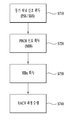
- FIG. 14 is a diagram for describing a method of repeatedly transmitting an MTC PBCH to an MTC terminal.
- a base station may repeatedly transmit a first PBCH (eg, PBCH (0)), which is a PBCH encoding bit block, to a MTC terminal in a legacy PBCH transmission region of a first subframe (eg, SF # 0). (S1410).
- PBCH (0) a PBCH encoding bit block
- the base station may repeatedly transmit a second PBCH (eg, PBCH (1), PBCH (2) or PBCH (3)), which is a PBCH encoding bead block, in the MTC transmission region of the first subframe to the MTC terminal ( S1420).
- a second PBCH eg, PBCH (1), PBCH (2) or PBCH (3)
- PBCH (1), PBCH (2) or PBCH (3) which is a PBCH encoding bead block
- step S1420 the base station performs remaining PBCH encoding bit blocks in a second subframe different from the first subframe (for example, SF # 1).
- a second subframe different from the first subframe for example, SF # 1.
- PBCH (1), PBCH (2) or PBCH (3) may be repeatedly transmitted to the MTC terminal (S1430).
- the MTC transmission area may mean a transmission area allocated for the MTC terminal.
- the MTC transmission region may be configured of a specific subframe or the center 6RB of each subframe.
- Sections 1 to 5 described above may be applied to the method described in FIG. 14.
- the methods described in section 5 may be applied.
- the legacy PBCH transmission region and the MTC transmission region may be referred to.
- the control region and the RE to which the RS is transmitted may be configured not to transmit the PBCH. have.
- FIG. 15 is a means in which the methods described in FIGS. 1 to 14 may be implemented.
- a UE may operate as a transmitting end in uplink and a receiving end in downlink.
- an e-Node B eNB
- eNB e-Node B
- the terminal and the base station may include transmitters 1540 and 1550 and receivers 1550 and 1570 to control transmission and reception of information, data and / or messages, respectively.
- the antenna may include antennas 1500 and 1510 for transmitting and receiving messages.
- the terminal and the base station may each include a processor 1520 and 1530 for performing the above-described embodiments of the present invention, and memories 1580 and 1590 for temporarily or continuously storing the processing of the processor. Can be.
- Embodiments of the present invention can be performed using the components and functions of the above-described terminal and base station apparatus.
- the processor of the base station may control the transmitter to perform PBCH repetitive transmission.
- the processor of the base station may repeatedly transmit the PBCH to the MTC terminal in the same subframe and other subframes to which the legacy PBCH transmission region and the legacy PBCH transmission region belong to repeatedly transmit the MTC PBCH to the MTC terminal.
- the processor of the base station transmits the PBCH in the control regions in which the PDCCH is transmitted and in REs in which a reference signal (for example, cell-specific and / or UE-specific reference signals) are transmitted. It can be configured not to.
- the processor of the UE may decode the corresponding subframes and receive the PBCH assuming that the PBCH is not repeatedly transmitted in these restricted areas. Such operations may be performed by applying the embodiments of the present invention described in Sections 1 to 5.
- the transmitter and the receiver included in the terminal and the base station include a packet modulation and demodulation function, a high speed packet channel coding function, an orthogonal frequency division multiple access (OFDMA) packet scheduling, and a time division duplex (TDD) for data transmission. Packet scheduling and / or channel multiplexing may be performed.
- the terminal and base station of FIG. 15 may further include a low power radio frequency (RF) / intermediate frequency (IF) unit.
- RF radio frequency
- IF intermediate frequency
- the terminal is a personal digital assistant (PDA), a cellular phone, a personal communication service (PCS) phone, a GSM (Global System for Mobile) phone, a WCDMA (Wideband CDMA) phone, an MBS.
- PDA personal digital assistant
- PCS personal communication service
- GSM Global System for Mobile
- WCDMA Wideband CDMA
- MBS Multi Mode-Multi Band
- a smart phone is a terminal that combines the advantages of a mobile communication terminal and a personal portable terminal, and may mean a terminal incorporating data communication functions such as schedule management, fax transmission and reception, which are functions of a personal mobile terminal, in a mobile communication terminal.
- a multimode multiband terminal can be equipped with a multi-modem chip to operate in both portable Internet systems and other mobile communication systems (e.g., code division multiple access (CDMA) 2000 systems, wideband CDMA (WCDMA) systems, etc.). Speak the terminal.
- CDMA code division multiple access
- WCDMA wideband CDMA
- Embodiments of the invention may be implemented through various means.
- embodiments of the present invention may be implemented by hardware, firmware, software, or a combination thereof.
- the method according to embodiments of the present invention may include one or more application specific integrated circuits (ASICs), digital signal processors (DSPs), digital signal processing devices (DSPDs), programmable logic devices (PLDs). Field programmable gate arrays (FPGAs), processors, controllers, microcontrollers, microprocessors, and the like.
- ASICs application specific integrated circuits
- DSPs digital signal processors
- DSPDs digital signal processing devices
- PLDs programmable logic devices
- FPGAs Field programmable gate arrays
- processors controllers, microcontrollers, microprocessors, and the like.
- the method according to the embodiments of the present invention may be implemented in the form of a module, a procedure, or a function that performs the functions or operations described above.
- software code may be stored in the memory units 1580 and 1590 and driven by the processors 1520 and 1530.
- the memory unit may be located inside or outside the processor, and may exchange data with the processor by various known means.
- Embodiments of the present invention can be applied to various wireless access systems.
- various radio access systems include 3rd Generation Partnership Project (3GPP), 3GPP2 and / or IEEE 802.xx (Institute of Electrical and Electronic Engineers 802) systems.
- Embodiments of the present invention can be applied not only to the various radio access systems, but also to all technical fields to which the various radio access systems are applied.
Landscapes
- Engineering & Computer Science (AREA)
- Signal Processing (AREA)
- Computer Networks & Wireless Communication (AREA)
- Mobile Radio Communication Systems (AREA)
Abstract
La présente invention concerne un système d'accès sans fil prenant en charge une communication de type machine (MTC), et, en particulier, un procédé pour transmettre de manière répétée un canal de diffusion physique (PBCH) pour une MTC, et des appareils pour prendre en charge ledit procédé. Le procédé pour transmettre de manière répétée un PBCH pour un terminal de MTC dans un système d'accès sans fil prenant en charge une MTC selon un mode de réalisation de la présente invention peut comprendre les étapes consistant à : transmettre un premier PBCH au moyen d'une région de transmission de PBCH patrimoniale d'une première sous-trame; transmettre de manière répétée un deuxième PBCH à partir de la première sous-trame; et transmettre de manière répétée un troisième PBCH à partir d'une seconde sous-trame. Ici, la présente invention peut être structurée de telle sorte que le deuxième PBCH et le troisième PBCH ne sont pas transmis de manière répétée dans les régions de commande de la première sous-trame et de la seconde sous-trame.
Priority Applications (1)
| Application Number | Priority Date | Filing Date | Title |
|---|---|---|---|
| US15/550,248 US20180054289A1 (en) | 2015-02-10 | 2016-02-05 | Method and apparatus for transceiving physical broadcast channel in wireless access system supporting machine-type communication |
Applications Claiming Priority (4)
| Application Number | Priority Date | Filing Date | Title |
|---|---|---|---|
| US201562114085P | 2015-02-10 | 2015-02-10 | |
| US62/114,085 | 2015-02-10 | ||
| US201562161911P | 2015-05-15 | 2015-05-15 | |
| US62/161,911 | 2015-05-15 |
Publications (1)
| Publication Number | Publication Date |
|---|---|
| WO2016129900A1 true WO2016129900A1 (fr) | 2016-08-18 |
Family
ID=56614542
Family Applications (1)
| Application Number | Title | Priority Date | Filing Date |
|---|---|---|---|
| PCT/KR2016/001324 Ceased WO2016129900A1 (fr) | 2015-02-10 | 2016-02-05 | Procédé et appareil pour transmettre-recevoir un canal de diffusion physique dans un système d'accès sans fil prenant en charge une communication de type machine |
Country Status (2)
| Country | Link |
|---|---|
| US (1) | US20180054289A1 (fr) |
| WO (1) | WO2016129900A1 (fr) |
Cited By (4)
| Publication number | Priority date | Publication date | Assignee | Title |
|---|---|---|---|---|
| CN110768752A (zh) * | 2019-10-30 | 2020-02-07 | 紫光展锐(重庆)科技有限公司 | 通信方式确定方法及装置 |
| US11218236B2 (en) | 2016-06-01 | 2022-01-04 | Qualcomm Incorporated | Time division multiplexing of synchronization channels |
| AU2017273612B2 (en) * | 2016-06-01 | 2022-01-27 | Qualcomm Incorporated | Time division multiplexing of synchronization channels |
| US11563505B2 (en) | 2016-06-01 | 2023-01-24 | Qualcomm Incorporated | Time division multiplexing of synchronization channels |
Families Citing this family (9)
| Publication number | Priority date | Publication date | Assignee | Title |
|---|---|---|---|---|
| US10292176B2 (en) * | 2015-07-16 | 2019-05-14 | Qualcomm Incorporated | Subframe availability for machine type communications (MTC) |
| CN111786765B (zh) * | 2016-05-09 | 2023-07-18 | 展讯通信(上海)有限公司 | 用户设备、网络侧设备及用户设备的控制方法 |
| US10887035B2 (en) | 2016-06-01 | 2021-01-05 | Qualcomm Incorporated | Time division multiplexing of synchronization channels |
| US10498437B2 (en) | 2016-06-01 | 2019-12-03 | Qualcomm Incorporated | Conveying hypotheses through resource selection of synchronization and broadcast channels |
| US10470191B2 (en) * | 2016-12-09 | 2019-11-05 | Samsung Electronics Co., Ltd. | Method and apparatus of broadcast signals and channels for system information transmission |
| WO2018145107A1 (fr) * | 2017-02-06 | 2018-08-09 | Motorola Mobility Llc | Transmission et réception d'un bloc de signaux de synchronisation |
| WO2019017751A1 (fr) * | 2017-07-21 | 2019-01-24 | 엘지전자 주식회사 | Procédé d'émission et de réception de signal de référence d'informations d'état de canal dans un système de communications sans fil, et appareil à cet effet |
| US10694480B2 (en) | 2017-08-11 | 2020-06-23 | Lenovo (Singapore) Pte. Ltd. | Determining synchronization signal block positions |
| CN110474705B (zh) * | 2018-05-11 | 2021-09-24 | 锐迪科(重庆)微电子科技有限公司 | 一种物理广播信道接收方法及装置 |
Citations (4)
| Publication number | Priority date | Publication date | Assignee | Title |
|---|---|---|---|---|
| US20140086111A1 (en) * | 2012-09-26 | 2014-03-27 | Samsung Electronics Co., Ltd. | Methods and devices for transmitting and receiving synchronous channels and broadcasting channels |
| WO2014069945A1 (fr) * | 2012-11-01 | 2014-05-08 | 엘지전자 주식회사 | Procédé et appareil d'émission-réception de signal de référence dans un système de communication sans fil |
| WO2014161630A1 (fr) * | 2013-04-05 | 2014-10-09 | Alcatel Lucent | Communication en liaison descendante à émissions répétées |
| WO2014204285A1 (fr) * | 2013-06-21 | 2014-12-24 | Lg Electronics Inc. | Procédé d'amélioration de la couverture d'un équipement utilisateur et appareil utilisant ce procédé |
-
2016
- 2016-02-05 WO PCT/KR2016/001324 patent/WO2016129900A1/fr not_active Ceased
- 2016-02-05 US US15/550,248 patent/US20180054289A1/en not_active Abandoned
Patent Citations (4)
| Publication number | Priority date | Publication date | Assignee | Title |
|---|---|---|---|---|
| US20140086111A1 (en) * | 2012-09-26 | 2014-03-27 | Samsung Electronics Co., Ltd. | Methods and devices for transmitting and receiving synchronous channels and broadcasting channels |
| WO2014069945A1 (fr) * | 2012-11-01 | 2014-05-08 | 엘지전자 주식회사 | Procédé et appareil d'émission-réception de signal de référence dans un système de communication sans fil |
| WO2014161630A1 (fr) * | 2013-04-05 | 2014-10-09 | Alcatel Lucent | Communication en liaison descendante à émissions répétées |
| WO2014204285A1 (fr) * | 2013-06-21 | 2014-12-24 | Lg Electronics Inc. | Procédé d'amélioration de la couverture d'un équipement utilisateur et appareil utilisant ce procédé |
Non-Patent Citations (1)
| Title |
|---|
| INTEL CORPORATION: "SCH and PBCH Enhancement for MTC", R1-144663, 3GPP TSG RAN WG1 MEETING #79, 8 November 2014 (2014-11-08), San Francisco, USA * |
Cited By (6)
| Publication number | Priority date | Publication date | Assignee | Title |
|---|---|---|---|---|
| US11218236B2 (en) | 2016-06-01 | 2022-01-04 | Qualcomm Incorporated | Time division multiplexing of synchronization channels |
| AU2017273612B2 (en) * | 2016-06-01 | 2022-01-27 | Qualcomm Incorporated | Time division multiplexing of synchronization channels |
| US11563505B2 (en) | 2016-06-01 | 2023-01-24 | Qualcomm Incorporated | Time division multiplexing of synchronization channels |
| US11616674B2 (en) | 2016-06-01 | 2023-03-28 | Qualcomm Incorporated | Time division multiplexing of synchronization channels |
| CN110768752A (zh) * | 2019-10-30 | 2020-02-07 | 紫光展锐(重庆)科技有限公司 | 通信方式确定方法及装置 |
| CN110768752B (zh) * | 2019-10-30 | 2022-01-28 | 紫光展锐(重庆)科技有限公司 | 通信方式确定方法及装置 |
Also Published As
| Publication number | Publication date |
|---|---|
| US20180054289A1 (en) | 2018-02-22 |
Similar Documents
| Publication | Publication Date | Title |
|---|---|---|
| WO2016129900A1 (fr) | Procédé et appareil pour transmettre-recevoir un canal de diffusion physique dans un système d'accès sans fil prenant en charge une communication de type machine | |
| WO2016114626A1 (fr) | Procédé et dispositif de transmission et de réception de message de commande partagé dans un système d'accès sans fil prenant en charge une communication de type machine | |
| WO2016122268A1 (fr) | Procédé et appareil d'émission-réception de message de commande commun dans un système d'accès sans fil prenant en charge l'internet des choses en bande étroite | |
| WO2017052199A1 (fr) | Procédé et équipement utilisateur permettant la réception d'informations de commande de liaison descendante, et procédé et station de base permettant l'émission d'informations de commande de liaison descendante | |
| WO2017057870A1 (fr) | Procédé et équipement utilisateur pour recevoir des informations de commande de liaison descendante, et procédé et station de base pour émettre des informations de commande de liaison descendante | |
| WO2014185673A1 (fr) | Procédé de communications prenant en considération le type de support et appareil associé | |
| WO2020145769A1 (fr) | Procédé de transmission de canal partagé de liaison montante dans un système de communication sans fil et dispositif faisant appel à celui-ci | |
| WO2017043878A1 (fr) | Procédé et appareil pour recevoir un canal physique de diffusion de liaison descendante dans un système d'accès radio qui prend en charge un internet des objets à bande étroite | |
| WO2016085295A1 (fr) | Procédé et appareil pour réaliser une communication de dispositif à dispositif directe dans un système de communication sans fil prenant en charge une bande non autorisée | |
| WO2016163802A1 (fr) | Procédé d'exécution de cca dans un système d'accès sans fil supportant une bande sans licence, et appareil le supportant | |
| WO2018128341A1 (fr) | Procédé de codage et d'émission d'un pbch et dispositif de communication associé | |
| WO2017018761A1 (fr) | Procédé de réception d'informations de commande et équipement d'utilisateur, et procédé de réception d'informations de commande et station de base | |
| WO2014123379A1 (fr) | Procédé d'émission-réception de signaux et appareil associé | |
| WO2017135696A1 (fr) | Procédé permettant de recevoir des données par un terminal dans un système de communication sans fil | |
| WO2018016923A1 (fr) | Procédé et équipement utilisateur permettant de recevoir un canal de liaison descendante, et procédé et station de base permettant de transmettre un canal de liaison descendante | |
| WO2017160100A2 (fr) | Procédé d'émission et de réception d'informations de commande dans un système de communication sans fil et appareil correspondant | |
| WO2013147532A1 (fr) | Procédé de mesure de canal à l'aide d'un signal de référence de suivi dans un système de communication sans fil et dispositif l'utilisant | |
| WO2017018759A1 (fr) | Procédé de réception de signal de liaison descendante, équipement d'utilisateur, procédé d'émission de signal de liaison descendante et station de base | |
| WO2016036097A1 (fr) | Procédé de mesure et de rapport d'état de canal dans un système d'accès sans fil prenant en charge une bande sans licence | |
| WO2017018758A1 (fr) | Procédé de réception d'informations de commande en liaison descendante et équipement d'utilisateur et procédé de transmission d'informations de commande en liaison descendante et station de base | |
| WO2013112032A1 (fr) | Équipement utilisateur et procédé de réception de signaux de synchronisation, et station de base et procédé de transmission de signaux de synchronisation | |
| WO2016167606A1 (fr) | Procédé pour réaliser une rétroaction par un terminal dans un système de communication sans fil et appareil associé | |
| WO2016093662A1 (fr) | Procédé et appareil pour émettre un signal de référence de positionnement dans un système d'accès sans fil prenant en charge la communication de type machine | |
| WO2016018079A1 (fr) | Procédé de réception de signaux en liaison descendante et équipement d'utilisateur, et procédé d'émission de signaux en liaison descendante et station de base | |
| WO2016021979A1 (fr) | Procédé et appareil d'utilisateur de réception de signal de synchronisation et procédé et station de base de transmission de signal de synchronisation |
Legal Events
| Date | Code | Title | Description |
|---|---|---|---|
| 121 | Ep: the epo has been informed by wipo that ep was designated in this application |
Ref document number: 16749440 Country of ref document: EP Kind code of ref document: A1 |
|
| WWE | Wipo information: entry into national phase |
Ref document number: 15550248 Country of ref document: US |
|
| NENP | Non-entry into the national phase |
Ref country code: DE |
|
| 122 | Ep: pct application non-entry in european phase |
Ref document number: 16749440 Country of ref document: EP Kind code of ref document: A1 |