WO2016132404A1 - Dispositif d'alimentation électrique - Google Patents
Dispositif d'alimentation électrique Download PDFInfo
- Publication number
- WO2016132404A1 WO2016132404A1 PCT/JP2015/003406 JP2015003406W WO2016132404A1 WO 2016132404 A1 WO2016132404 A1 WO 2016132404A1 JP 2015003406 W JP2015003406 W JP 2015003406W WO 2016132404 A1 WO2016132404 A1 WO 2016132404A1
- Authority
- WO
- WIPO (PCT)
- Prior art keywords
- power supply
- supply device
- storage member
- pouch
- pair
- Prior art date
- Legal status (The legal status is an assumption and is not a legal conclusion. Google has not performed a legal analysis and makes no representation as to the accuracy of the status listed.)
- Ceased
Links
Images


Classifications
-
- H—ELECTRICITY
- H01—ELECTRIC ELEMENTS
- H01M—PROCESSES OR MEANS, e.g. BATTERIES, FOR THE DIRECT CONVERSION OF CHEMICAL ENERGY INTO ELECTRICAL ENERGY
- H01M50/00—Constructional details or processes of manufacture of the non-active parts of electrochemical cells other than fuel cells, e.g. hybrid cells
- H01M50/30—Arrangements for facilitating escape of gases
-
- H—ELECTRICITY
- H01—ELECTRIC ELEMENTS
- H01M—PROCESSES OR MEANS, e.g. BATTERIES, FOR THE DIRECT CONVERSION OF CHEMICAL ENERGY INTO ELECTRICAL ENERGY
- H01M50/00—Constructional details or processes of manufacture of the non-active parts of electrochemical cells other than fuel cells, e.g. hybrid cells
- H01M50/20—Mountings; Secondary casings or frames; Racks, modules or packs; Suspension devices; Shock absorbers; Transport or carrying devices; Holders
- H01M50/204—Racks, modules or packs for multiple batteries or multiple cells
- H01M50/207—Racks, modules or packs for multiple batteries or multiple cells characterised by their shape
- H01M50/211—Racks, modules or packs for multiple batteries or multiple cells characterised by their shape adapted for pouch cells
-
- H—ELECTRICITY
- H01—ELECTRIC ELEMENTS
- H01M—PROCESSES OR MEANS, e.g. BATTERIES, FOR THE DIRECT CONVERSION OF CHEMICAL ENERGY INTO ELECTRICAL ENERGY
- H01M50/00—Constructional details or processes of manufacture of the non-active parts of electrochemical cells other than fuel cells, e.g. hybrid cells
- H01M50/20—Mountings; Secondary casings or frames; Racks, modules or packs; Suspension devices; Shock absorbers; Transport or carrying devices; Holders
- H01M50/289—Mountings; Secondary casings or frames; Racks, modules or packs; Suspension devices; Shock absorbers; Transport or carrying devices; Holders characterised by spacing elements or positioning means within frames, racks or packs
- H01M50/291—Mountings; Secondary casings or frames; Racks, modules or packs; Suspension devices; Shock absorbers; Transport or carrying devices; Holders characterised by spacing elements or positioning means within frames, racks or packs characterised by their shape
-
- H—ELECTRICITY
- H01—ELECTRIC ELEMENTS
- H01M—PROCESSES OR MEANS, e.g. BATTERIES, FOR THE DIRECT CONVERSION OF CHEMICAL ENERGY INTO ELECTRICAL ENERGY
- H01M50/00—Constructional details or processes of manufacture of the non-active parts of electrochemical cells other than fuel cells, e.g. hybrid cells
- H01M50/30—Arrangements for facilitating escape of gases
- H01M50/342—Non-re-sealable arrangements
- H01M50/3425—Non-re-sealable arrangements in the form of rupturable membranes or weakened parts, e.g. pierced with the aid of a sharp member
-
- H—ELECTRICITY
- H01—ELECTRIC ELEMENTS
- H01M—PROCESSES OR MEANS, e.g. BATTERIES, FOR THE DIRECT CONVERSION OF CHEMICAL ENERGY INTO ELECTRICAL ENERGY
- H01M50/00—Constructional details or processes of manufacture of the non-active parts of electrochemical cells other than fuel cells, e.g. hybrid cells
- H01M50/30—Arrangements for facilitating escape of gases
- H01M50/35—Gas exhaust passages comprising elongated, tortuous or labyrinth-shaped exhaust passages
- H01M50/358—External gas exhaust passages located on the battery cover or case
-
- H—ELECTRICITY
- H01—ELECTRIC ELEMENTS
- H01M—PROCESSES OR MEANS, e.g. BATTERIES, FOR THE DIRECT CONVERSION OF CHEMICAL ENERGY INTO ELECTRICAL ENERGY
- H01M50/00—Constructional details or processes of manufacture of the non-active parts of electrochemical cells other than fuel cells, e.g. hybrid cells
- H01M50/30—Arrangements for facilitating escape of gases
- H01M50/35—Gas exhaust passages comprising elongated, tortuous or labyrinth-shaped exhaust passages
- H01M50/367—Internal gas exhaust passages forming part of the battery cover or case; Double cover vent systems
-
- H—ELECTRICITY
- H01—ELECTRIC ELEMENTS
- H01M—PROCESSES OR MEANS, e.g. BATTERIES, FOR THE DIRECT CONVERSION OF CHEMICAL ENERGY INTO ELECTRICAL ENERGY
- H01M2220/00—Batteries for particular applications
- H01M2220/20—Batteries in motive systems, e.g. vehicle, ship, plane
-
- Y—GENERAL TAGGING OF NEW TECHNOLOGICAL DEVELOPMENTS; GENERAL TAGGING OF CROSS-SECTIONAL TECHNOLOGIES SPANNING OVER SEVERAL SECTIONS OF THE IPC; TECHNICAL SUBJECTS COVERED BY FORMER USPC CROSS-REFERENCE ART COLLECTIONS [XRACs] AND DIGESTS
- Y02—TECHNOLOGIES OR APPLICATIONS FOR MITIGATION OR ADAPTATION AGAINST CLIMATE CHANGE
- Y02E—REDUCTION OF GREENHOUSE GAS [GHG] EMISSIONS, RELATED TO ENERGY GENERATION, TRANSMISSION OR DISTRIBUTION
- Y02E60/00—Enabling technologies; Technologies with a potential or indirect contribution to GHG emissions mitigation
- Y02E60/10—Energy storage using batteries
Definitions
- the present invention relates to a power supply device.
- a power supply device that is used in a power storage system combined with a power generation device such as a solar cell and stores power generated by the power generation device is also known.
- a chargeable / dischargeable secondary battery such as a lithium ion battery or a nickel metal hydride battery is used.
- Known battery cells include a prismatic battery having an outer package constituted by a metal outer can, and a pouch battery formed of a thin laminate film and having a low rigidity outer package.
- the internal pressure of the battery cell rises and gas is generated in the exterior body.
- the exterior body of the prismatic battery is composed of a bottomed metal can that is open on one side and a sealing body that closes the release surface of the metal can.
- the sealing body is provided with a safety valve, and when the pressure in the outer can rises, the safety valve opens and gas can be discharged.
- the exterior body of the pouch battery is composed of a single laminate film. Specifically, a power generation element such as an electrode plate is wrapped with a laminate film, and the laminated film is heat-welded to seal four sides to form an exterior body. In the case of the battery cell having such a configuration, when the internal pressure of the battery cell exterior body increases, the heat-welded portion of the laminate film peels off or breaks, and the gas generated in the exterior body is discharged. Therefore, in the case of a pouch battery, there is a problem that it is difficult to specify the position where the gas is discharged.
- the pouch battery disclosed in the following patent document is provided with a place where the adhesive strength of the thermal welding is intentionally reduced by a method such as changing the area to be thermally welded when the laminate film is thermally welded.
- a gas discharge part is formed in a part of the heat welding part of the film.
- the gas discharged from the battery cell can be led to a predetermined place.
- a configuration including a duct arranged in close contact with a safety valve is known.
- the exterior body can be deformed. It is difficult to connect the discharge part and the duct in an airtight manner.
- the present invention has been made in view of such a situation, and a main object thereof is to provide a power supply device having a structure capable of airtightly connecting a gas discharge portion of a pouch battery and a duct. It is in.
- a power supply device includes one or a plurality of pouch batteries having a laminate film outer package, and a storage member that surrounds the one or more pouch batteries.
- Each of the one or more pouch batteries includes a thermal welding part formed by thermally welding the laminate film, and a gas discharge part provided in at least a part of the thermal welding part. It is out.
- the storage member has an outlet that communicates with the gas outlet of the one or more pouch batteries.
- the gas discharged from the outer body of the pouch battery is discharged from the discharge port of the storage member surrounding the pouch battery.
- the housing member can connect the gas discharge part of the pouch battery and the duct by connecting the duct to the discharge port.
- FIG. 6 is a rear perspective view of the power supply device of FIG. 5.
- FIG. 5 is a disassembled perspective view of the power supply device of FIG.
- 2nd embodiment of this invention it is a perspective view for demonstrating the connection structure of the connection part of a several power supply device.
- It is a disassembled perspective view of the unit module of FIG. It is sectional drawing of the unit module of the other Example in 2nd embodiment of this invention. It is a disassembled perspective view of the unit module of FIG.
- the power supply device 1 according to the first embodiment of the present invention will be described in detail below with reference to FIGS.
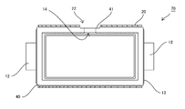
- the power supply device 1 shown in FIGS. 1 to 3 includes a plurality of pouch batteries 10, a storage member 20 having a cylindrical outer shape, and a pair of resin members 30 fitted into the storage member 20.
- the plurality of pouch batteries 10 are arranged inside the storage member 20.
- As the pouch battery 10 various secondary batteries such as a lithium ion battery and a nickel metal hydride battery can be used.
- the pouch battery 10 is a pair of an exterior body 11 formed of a deformable laminate film, a power generation element enclosed in the exterior body 11, and a power for outputting power generated by the power generation element.
- the power generation element includes an electrode body and an electrolytic solution.
- the electrode tab 12 is an output terminal of the pouch battery 10, and is led out from the inside of the exterior body 11 to the outside of the exterior body 11.
- This type of pouch battery is known to have a flat wound electrode body or a laminated electrode body as an electrode body.
- the wound electrode body is an electrode body formed in a flat shape by winding a positive electrode plate and a negative electrode plate through a separator, and then pressing them.
- the laminated electrode body is an electrode body formed by laminating a sheet-like positive electrode plate and a negative electrode plate via a separator.
- a sheet-like composite film having a five-layer structure of resin layer (polypropylene) / adhesive layer / aluminum alloy layer / adhesive layer / resin layer (polypropylene) is known. Yes.
- the electrode body is not necessarily limited to the above-described configuration as long as the power generation element can be enclosed in the exterior body 11.
- the laminate film composite films having various structures can be used.
- the pouch battery 10 illustrated in FIG. 4 is formed by disposing an electrode body on a single laminate film, folding the laminate film, and thermally welding the laminated films that overlap each other on the folded side.
- the exterior body 11 has the heat-welded portion 13 formed on at least a part of the periphery of the exterior body. Specifically, in FIG. 3, the hatched region corresponds to the heat welded portion 13.
- the heat welding part 13 includes a pair of lead-out parts 15 provided at both ends of the exterior body 11 and a gas discharge part 14 provided between the pair of lead-out parts 15.
- the lead-out portion 15 is formed by heat welding with the electrode tab 12 interposed between two laminate films.
- the electrode tabs 12 are led out from the respective lead-out portions 15, and the power generated by the power generation element in the exterior body 11 can be taken out via the electrode tabs 12.
- the gas discharge part 14 is configured so that the bonding strength is weaker than the other areas of the heat weld part 13.
- the gas discharge part 14 is formed by making the width of the area of the portion to be thermally welded narrower than that of the other regions and thermally welding the laminate film. According to this configuration, when the internal pressure of the exterior body 11 is increased, first, the thermally welded portion of the gas discharge portion 14 is peeled off or broken, so that the gas generation location of the pouch battery is specified. can do.
- the cylindrical storage member 20 has openings 21 at both ends. Further, the storage member 20 is provided with a discharge port 22 in addition to the openings provided in the openings 21 at both ends.
- the discharge port 22 is provided on the side surface of the cylindrical storage member 20.
- the storage member 20 is preferably formed of a hard material such as metal and is configured to have relatively high rigidity.
- the storage member 20 can also be formed by combining a pair of plates 20a.
- the pair of plates 20a are fitted so as to overlap each other, so that the plurality of pouch batteries 10 disposed between the plates 20a are accommodated.
- the pair of plates 20a are each provided with a notch, and the discharge port 22 is formed when the housing member 20 is formed by being combined.
- a labyrinth structure may be formed in the fitting portion of the pair of plates 20 a to improve the airtightness in the storage member 20.
- airtightness can also be improved by welding the overlapping part of the two plates 20a.
- the plurality of pouch batteries 10 stored in the storage member 20 are stacked with their wide surfaces facing each other.
- the plurality of pouch batteries 10 are stacked in a predetermined posture, and the electrode tabs 12 of the adjacent pouch batteries 10 are close to each other, and the gas discharge portions 14 of the adjacent pouch batteries 10 are close to each other.
- the plurality of pouch batteries 10 in a stacked state are stored in the storage member 20 in a predetermined posture so that the gas discharge portions 14 of the respective pouch batteries are in positions corresponding to the discharge ports 22 of the storage member 20.
- the pair of resin members 30 are fitted into the openings 21 of the storage member 20 so as to cover the openings of the openings 21.
- the resin member 30 has a through hole for inserting the electrode tab 12 of the pouch battery 10.
- Part of the pouch battery 10 including the electrode tab 12 and the lead-out portion 15 is inserted into the through hole.
- a seal member such as an elastic body may be disposed between each resin member 30 and the inner wall of the storage member 20 or between the inner wall of the through hole of each resin member 30 and the pouch battery 10.
- the sealing member disposed on the inner wall of the through hole of the resin member 30 is preferably provided at a position where the thermal welding portion 13 of the pouch battery 10 is held. With this configuration, the adhesive strength of the laminate film constituting the lead-out portion 15 can be increased.
- the thermally welded portion of the lead-out unit 15 may peel off. Although it may break, it can prevent that gas is discharged from fields other than gas discharge part 14 of heat welding part 13 by setting it as the above-mentioned composition.
- the power supply device 1 having the above configuration is arranged such that the gas discharge portions 14 of the plurality of pouch batteries 10 correspond to the positions of the discharge ports 22 of the storage member 20. According to this configuration, the gas discharged from the pouch battery is discharged toward the discharge port 22. The gas discharged from the pouch battery 10 can be guided into the duct by airtightly connecting the storage member 20 and the duct on the vehicle side. Although it is difficult to airtightly connect a low-rigidity body such as an exterior body formed of a laminate film and a duct, it is relatively easy to airtightly connect a high-rigidity storage member and a duct. Therefore, the above-described power supply apparatus can guide the gas discharged from the pouch battery 10 into the duct, while having a relatively simple structure.
- the gas discharge portion 14 is not necessarily connected to the discharge port 22 of the storage member 20. It is not necessary to correspond to the position.
- the configuration of the gas discharge unit can be simplified.
- a pouch battery including an exterior body in which a laminate film is heat-welded with a uniform width can be employed.
- the adhesive strength of the heat welded portion is also uniform, the entire heat welded portion becomes the gas discharge portion 14.
- the airtightness in the housing member 20 is high, it occurs inside the housing member 20. The discharged gas is discharged from the discharge port 22 to the outside of the storage member 20.
- the storage member 20 stores a plurality of pouch batteries 10 therein, and can discharge the gas discharged from the pouch battery 10 from the discharge port 22 of the storage member 20.
- the storage member 20 has higher shape stability than the exterior body 11 of the pouch battery 10, and can easily connect a duct for guiding the gas discharged from the pouch battery to a predetermined position.
- the power supply apparatus shown in FIGS. 5 to 8 includes a case 60 for housing a plurality of pouch batteries 10.
- the case 60 includes a first case body 61 having an opening that opens on the upper surface, and a second case body 62 that closes the opening of the first case body 61.
- the second case body 62 is provided with a duct portion 63 at the top. The duct portion 63 extends along the stacking direction of the plurality of pouch batteries 10 housed in the case 60.
- the second case body 62 is provided with connecting portions 64 on both end surfaces in the extending direction of the duct portion 63.
- Each of the connecting portions 64 has a connecting hole that communicates with the duct portion 63, but the outer shape is different.
- the pair of connecting portions 64 are formed in a shape in which the respective connecting portions 64 can be fitted so that the duct portions 63 of the plurality of second case bodies 62 can be connected.
- FIG. 9 illustrates a state in which the connecting portions 64 of the plurality of power supply devices 1 are connected. As shown in FIG. 9, by arranging a plurality of power supply devices 1 including cases 60 adjacent to each other, the duct portions 63 of the respective power supply devices 1 can be directly connected. Therefore, the member for connecting the duct part 63 of each power supply device 1 can be made unnecessary.
- each unit module 70 includes a plurality of pouch batteries 10.
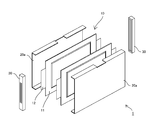
- a unit module 70 illustrated in FIG. 7 includes a plurality of pouch batteries 10, a holding body 40 that covers the gas discharge portion 14 of the pouch battery 10, and a storage member 20 that stores the plurality of pouch batteries 10 and the plurality of holding bodies 40. And.
- the holding body 40 is made of two resin members and holds at least a part of the heat welding part 13 excluding the gas discharge part 14.
- the holding body 40 has a through-hole portion 41 provided at a position corresponding to the gas discharge portion 14.
- the discharge port 22 of the storage member 20 is provided at a position corresponding to the gas discharge portion 14 of the pouch battery stored in the storage member 20. Therefore, as shown in FIG. 7, the through-hole portion 41 of the holding body 40 is exposed from the discharge port 22 of the storage member 20 by arranging the pouch battery 10 with the holding body 40 mounted in the storage member 20. It has come to be.
- the thickness of the holding body 40 is such that the holding body abuts against the inner wall of the storage member 20 when a plurality of pouch batteries held by the holding body 40 are stored inside the storage member 20. It is preferable to do. According to this configuration, in the state in which the holding body 40 is stored in the storage member 20, it is possible to suppress a shift in the relative position between the through-hole portion 41 and the discharge port 22 of the storage member 20.
- FIG. 12 and 13 is a modification of the holding body 40 shown in FIGS. 10 and 11.
- the holding body 40 illustrated in FIGS. 12 and 13 extends along the periphery of the pouch battery 10, and holds the heat welding part 13 excluding the gas discharge part 14. According to this structure, the adhesive strength of the heat welding part 13 except the gas discharge part 14 can be improved, and it can prevent that gas is discharged
- the power supply device 1 includes a first case body 61, a second case body 62, a plurality of unit modules 70, and a second case body 62. And an elastic member 50 disposed between the unit modules 70.
- the plurality of unit modules 70 are inserted from the opening of the first case body 61 so that the through hole 41 of the holding body 40 faces the upper surface.
- the elastic member 50 is disposed in the through hole portion 41 so as to extend along the opening edge of the through hole of the through hole portion 41.
- the elastic member 50 illustrated in FIG. 7 corresponds to a sheet-like member in which an opening is formed.
- the second case body 62 is connected to the first case body 61 in which a plurality of unit modules 70 are arranged.
- the second case body 62 is provided with a duct portion 63 at a position corresponding to the through hole portion 41 of the holding body 40.
- the elastic member 50 is located between the through hole 41 of the holding body 40 and the second case body 62.
- the holding body 40 can form a flat surface at the periphery of the through hole of the through hole portion 41 located above the gas discharge portion 14 of the pouch battery 10 by the above-described configuration. Further, the holding body 40 has higher rigidity than the exterior body 11 of the pouch battery 10. Therefore, by arranging the duct so as to press the elastic member 50 toward the holding body 40, the duct and the through-hole portion 41 of the holding body 40 can be easily connected in an airtight manner.
- the gas discharged from the gas discharge portion 14 of the pouch battery 10 is guided to the duct portion 63 of the second case body 62 through the discharge port 22 of the storage member 20.
- the gas that has flowed into the duct portion 63 is discharged from the connecting hole of the connecting portion 64 that is also received by the duct portion 63. Therefore, the gas discharged from the pouch battery can be easily guided to a predetermined position by connecting a connecting hose or the like to the connecting portion 64.
Landscapes
- Chemical & Material Sciences (AREA)
- Chemical Kinetics & Catalysis (AREA)
- Electrochemistry (AREA)
- General Chemical & Material Sciences (AREA)
- Sealing Battery Cases Or Jackets (AREA)
- Gas Exhaust Devices For Batteries (AREA)
- Battery Mounting, Suspending (AREA)
Abstract
Priority Applications (2)
| Application Number | Priority Date | Filing Date | Title |
|---|---|---|---|
| JP2017500478A JP6376273B2 (ja) | 2015-02-16 | 2015-07-07 | 電源装置 |
| US15/527,321 US10446818B2 (en) | 2015-02-16 | 2015-07-07 | Power source device |
Applications Claiming Priority (2)
| Application Number | Priority Date | Filing Date | Title |
|---|---|---|---|
| JP2015-027159 | 2015-02-16 | ||
| JP2015027159 | 2015-02-16 |
Publications (1)
| Publication Number | Publication Date |
|---|---|
| WO2016132404A1 true WO2016132404A1 (fr) | 2016-08-25 |
Family
ID=56692036
Family Applications (1)
| Application Number | Title | Priority Date | Filing Date |
|---|---|---|---|
| PCT/JP2015/003406 Ceased WO2016132404A1 (fr) | 2015-02-16 | 2015-07-07 | Dispositif d'alimentation électrique |
Country Status (3)
| Country | Link |
|---|---|
| US (1) | US10446818B2 (fr) |
| JP (1) | JP6376273B2 (fr) |
| WO (1) | WO2016132404A1 (fr) |
Cited By (29)
| Publication number | Priority date | Publication date | Assignee | Title |
|---|---|---|---|---|
| CN108539248A (zh) * | 2018-06-12 | 2018-09-14 | 华霆(合肥)动力技术有限公司 | 软包电池模组及膨胀检测方法 |
| JP2019012604A (ja) * | 2017-06-29 | 2019-01-24 | 株式会社村田製作所 | 電池ホルダおよび電池パック |
| JP2019186039A (ja) * | 2018-04-10 | 2019-10-24 | カルソニックカンセイ株式会社 | 組電池 |
| JP2020119765A (ja) * | 2019-01-24 | 2020-08-06 | Tdk株式会社 | 電池パック |
| JP2021174579A (ja) * | 2020-04-20 | 2021-11-01 | 日本特殊陶業株式会社 | 電池 |
| CN114361677A (zh) * | 2020-10-14 | 2022-04-15 | 株式会社Lg新能源 | 电池模块和包括该电池模块的电池组 |
| CN114497830A (zh) * | 2020-10-28 | 2022-05-13 | 大众汽车股份公司 | 电池单元模块以及用于制造这样的模块的方法 |
| WO2022249538A1 (fr) * | 2021-05-26 | 2022-12-01 | 株式会社豊田自動織機 | Module de stockage d'énergie électrique |
| JP2022551237A (ja) * | 2020-04-29 | 2022-12-08 | エルジー エナジー ソリューション リミテッド | 電池パックおよびこれを含むデバイス |
| JP2023510555A (ja) * | 2020-01-13 | 2023-03-14 | ビーワイディー カンパニー リミテッド | 電池、電池モジュール、電池パック及び電気自動車 |
| JP2023533738A (ja) * | 2021-03-04 | 2023-08-04 | エルジー エナジー ソリューション リミテッド | 火事防止性能が向上したバッテリーモジュール |
| WO2023176568A1 (fr) * | 2022-03-17 | 2023-09-21 | 株式会社Gsユアサ | Élément de stockage d'énergie et dispositif de stockage d'énergie |
| JP2024508121A (ja) * | 2021-12-24 | 2024-02-22 | エルジー エナジー ソリューション リミテッド | 安全性が強化されたバッテリーモジュール |
| JP2024512930A (ja) * | 2022-01-07 | 2024-03-21 | エルジー エナジー ソリューション リミテッド | 火炎遮断部材が付加されたバスバーを含む電池セルアセンブリ及びこれを含む電池セルアセンブリ構造体 |
| JP2024528637A (ja) * | 2022-01-12 | 2024-07-30 | 寧徳時代新能源科技股▲分▼有限公司 | 電池、電力消費機器、電池の製造方法及び機器 |
| JP2024531807A (ja) * | 2022-07-20 | 2024-08-29 | エルジー エナジー ソリューション リミテッド | バッテリーアセンブリ及びこれを含むバッテリーパック、並びに車両 |
| EP4175040A4 (fr) * | 2021-06-21 | 2024-09-18 | LG Energy Solution, Ltd. | Bloc-batterie et dispositif le comprenant |
| JP2024534401A (ja) * | 2022-07-20 | 2024-09-20 | エルジー エナジー ソリューション リミテッド | バッテリパックおよびこれを含むデバイス |
| JP2024546057A (ja) * | 2022-07-20 | 2024-12-17 | エルジー エナジー ソリューション リミテッド | 電池パックおよびこれを含むデバイス |
| JP2024546809A (ja) * | 2022-08-31 | 2024-12-26 | エルジー エナジー ソリューション リミテッド | バッテリーパック、バッテリーモジュール及びこれを含む自動車 |
| JP2025500817A (ja) * | 2022-07-20 | 2025-01-15 | エルジー エナジー ソリューション リミテッド | バッテリーパック及びこれを含む自動車 |
| JP2025503666A (ja) * | 2022-04-15 | 2025-02-04 | エルジー エナジー ソリューション リミテッド | 安全性が強化されたバッテリーモジュール |
| JP2025512941A (ja) * | 2022-12-09 | 2025-04-22 | エルジー エナジー ソリューション リミテッド | バッテリーセル、該バッテリーセルを含むバッテリーパック及び車両 |
| JP2025524605A (ja) * | 2022-07-20 | 2025-07-30 | エルジー エナジー ソリューション リミテッド | バッテリーパックおよびバッテリーモジュール |
| JP2025524889A (ja) * | 2022-08-02 | 2025-08-01 | エルジー エナジー ソリューション リミテッド | 二次電池モジュール |
| JP7722550B1 (ja) * | 2024-12-26 | 2025-08-13 | 大日本印刷株式会社 | 蓄電デバイス、蓄電モジュール及び移動体 |
| JP2025528885A (ja) * | 2022-09-30 | 2025-09-02 | エルジー エナジー ソリューション リミテッド | バッテリーパック及びこれを含む自動車 |
| JP2025538248A (ja) * | 2022-11-25 | 2025-11-26 | エルジー エナジー ソリューション リミテッド | 電池モジュール |
| JP7853522B2 (ja) | 2022-11-25 | 2026-04-28 | エルジー エナジー ソリューション リミテッド | 電池モジュール |
Families Citing this family (14)
| Publication number | Priority date | Publication date | Assignee | Title |
|---|---|---|---|---|
| CA2976877C (fr) | 2015-02-18 | 2022-06-21 | Ttb Holding Company Limited | Module de batterie lithium-ion a systeme de refroidissement |
| US10243186B2 (en) | 2015-03-06 | 2019-03-26 | Ttb Holding Company Limited | Battery module with thermal runaway and gas exhaust management system |
| US11121426B2 (en) * | 2017-11-30 | 2021-09-14 | William Koetting | Battery module including nodal cell compression and heat rejection |
| US11296386B2 (en) | 2019-02-06 | 2022-04-05 | GS Yuasa Lithium Power Inc. | Expandable electrochemical cell effluent containment device and corresponding systems and methods |
| DE102020216383A1 (de) * | 2020-12-21 | 2022-06-23 | Volkswagen Aktiengesellschaft | Batteriezellenmodul und Batterie |
| US12255348B2 (en) | 2021-04-15 | 2025-03-18 | Lg Energy Solution, Ltd. | Secondary battery |
| US20230043355A1 (en) * | 2021-08-04 | 2023-02-09 | Lg Energy Solution, Ltd. | Battery pack and vehicle including the same |
| US11984611B2 (en) * | 2021-08-17 | 2024-05-14 | Beta Air, Llc | Stack battery pack for electric vertical take-off and landing aircraft |
| KR102734328B1 (ko) * | 2021-11-12 | 2024-11-27 | 주식회사 엘지에너지솔루션 | 배터리 모듈 및 이를 포함한 배터리 팩 |
| EP4407774B1 (fr) * | 2022-07-20 | 2026-03-04 | LG Energy Solution, Ltd. | Unité cellule de batterie, et bloc-batterie et véhicule la comprenant |
| WO2024019459A1 (fr) * | 2022-07-20 | 2024-01-25 | 주식회사 엘지에너지솔루션 | Bloc-batterie et véhicule le comprenant |
| WO2024019400A1 (fr) * | 2022-07-20 | 2024-01-25 | 주식회사 엘지에너지솔루션 | Bloc-batterie et véhicule le comprenant |
| CN120266324A (zh) * | 2022-11-25 | 2025-07-04 | 株式会社Lg新能源 | 电池模块 |
| KR20260048006A (ko) * | 2024-10-02 | 2026-04-09 | 주식회사 엘지에너지솔루션 | 이차 전지 |
Citations (4)
| Publication number | Priority date | Publication date | Assignee | Title |
|---|---|---|---|---|
| JP2005302501A (ja) * | 2004-04-12 | 2005-10-27 | Uchiyama Mfg Corp | バッテリーセル用ケース |
| JP2006236605A (ja) * | 2005-02-22 | 2006-09-07 | Nec Lamilion Energy Ltd | フィルム外装電気デバイス集合体 |
| JP2011054420A (ja) * | 2009-09-02 | 2011-03-17 | Nissan Motor Co Ltd | 電池モジュール、組電池、および電池モジュールの製造方法 |
| JP2012028353A (ja) * | 2004-03-31 | 2012-02-09 | Nec Corp | フィルム外装電気デバイスおよびフィルム外装電気デバイス収納システム |
Family Cites Families (6)
| Publication number | Priority date | Publication date | Assignee | Title |
|---|---|---|---|---|
| KR100932227B1 (ko) * | 2005-09-02 | 2009-12-16 | 주식회사 엘지화학 | 이차전지 및 이를 포함하는 전지모듈 |
| WO2008026854A1 (fr) * | 2006-08-28 | 2008-03-06 | Lg Chem, Ltd. | Accumulateur comprenant une soupape d'échappement de non retour |
| JP5331517B2 (ja) * | 2008-04-14 | 2013-10-30 | 日産自動車株式会社 | 組電池、および組電池を搭載した車両 |
| KR101680709B1 (ko) * | 2010-11-12 | 2016-12-12 | 에스케이이노베이션 주식회사 | 배터리 모듈 케이스 |
| KR20130052892A (ko) | 2011-11-14 | 2013-05-23 | 에스케이이노베이션 주식회사 | 배터리셀, 및 이를 포함하는 배터리 모듈 |
| JP5925220B2 (ja) * | 2012-02-14 | 2016-05-25 | 住友重機械工業株式会社 | ショベル |
-
2015
- 2015-07-07 WO PCT/JP2015/003406 patent/WO2016132404A1/fr not_active Ceased
- 2015-07-07 US US15/527,321 patent/US10446818B2/en active Active
- 2015-07-07 JP JP2017500478A patent/JP6376273B2/ja active Active
Patent Citations (4)
| Publication number | Priority date | Publication date | Assignee | Title |
|---|---|---|---|---|
| JP2012028353A (ja) * | 2004-03-31 | 2012-02-09 | Nec Corp | フィルム外装電気デバイスおよびフィルム外装電気デバイス収納システム |
| JP2005302501A (ja) * | 2004-04-12 | 2005-10-27 | Uchiyama Mfg Corp | バッテリーセル用ケース |
| JP2006236605A (ja) * | 2005-02-22 | 2006-09-07 | Nec Lamilion Energy Ltd | フィルム外装電気デバイス集合体 |
| JP2011054420A (ja) * | 2009-09-02 | 2011-03-17 | Nissan Motor Co Ltd | 電池モジュール、組電池、および電池モジュールの製造方法 |
Cited By (47)
| Publication number | Priority date | Publication date | Assignee | Title |
|---|---|---|---|---|
| JP2019012604A (ja) * | 2017-06-29 | 2019-01-24 | 株式会社村田製作所 | 電池ホルダおよび電池パック |
| JP2019186039A (ja) * | 2018-04-10 | 2019-10-24 | カルソニックカンセイ株式会社 | 組電池 |
| CN108539248A (zh) * | 2018-06-12 | 2018-09-14 | 华霆(合肥)动力技术有限公司 | 软包电池模组及膨胀检测方法 |
| CN108539248B (zh) * | 2018-06-12 | 2023-11-21 | 华霆(合肥)动力技术有限公司 | 软包电池模组及膨胀检测方法 |
| JP2020119765A (ja) * | 2019-01-24 | 2020-08-06 | Tdk株式会社 | 電池パック |
| JP7180407B2 (ja) | 2019-01-24 | 2022-11-30 | Tdk株式会社 | 電池パック |
| JP2023510555A (ja) * | 2020-01-13 | 2023-03-14 | ビーワイディー カンパニー リミテッド | 電池、電池モジュール、電池パック及び電気自動車 |
| JP2021174579A (ja) * | 2020-04-20 | 2021-11-01 | 日本特殊陶業株式会社 | 電池 |
| JP7473383B2 (ja) | 2020-04-20 | 2024-04-23 | 日本特殊陶業株式会社 | 電池 |
| JP2022551237A (ja) * | 2020-04-29 | 2022-12-08 | エルジー エナジー ソリューション リミテッド | 電池パックおよびこれを含むデバイス |
| US12294106B2 (en) | 2020-04-29 | 2025-05-06 | Lg Energy Solution, Ltd. | Battery pack and device including the same |
| JP7482996B2 (ja) | 2020-04-29 | 2024-05-14 | エルジー エナジー ソリューション リミテッド | 電池パックおよびこれを含むデバイス |
| JP2023521703A (ja) * | 2020-10-14 | 2023-05-25 | エルジー エナジー ソリューション リミテッド | 電池モジュールおよびこれを含む電池パック |
| JP7625318B2 (ja) | 2020-10-14 | 2025-02-03 | エルジー エナジー ソリューション リミテッド | 電池モジュールおよびこれを含む電池パック |
| CN114361677A (zh) * | 2020-10-14 | 2022-04-15 | 株式会社Lg新能源 | 电池模块和包括该电池模块的电池组 |
| CN114497830A (zh) * | 2020-10-28 | 2022-05-13 | 大众汽车股份公司 | 电池单元模块以及用于制造这样的模块的方法 |
| JP2023533738A (ja) * | 2021-03-04 | 2023-08-04 | エルジー エナジー ソリューション リミテッド | 火事防止性能が向上したバッテリーモジュール |
| JP7660184B2 (ja) | 2021-03-04 | 2025-04-10 | エルジー エナジー ソリューション リミテッド | 火事防止性能が向上したバッテリーモジュール |
| JP2022181524A (ja) * | 2021-05-26 | 2022-12-08 | 株式会社豊田自動織機 | 蓄電モジュール |
| WO2022249538A1 (fr) * | 2021-05-26 | 2022-12-01 | 株式会社豊田自動織機 | Module de stockage d'énergie électrique |
| JP7571661B2 (ja) | 2021-05-26 | 2024-10-23 | 株式会社豊田自動織機 | 蓄電モジュール |
| EP4175040A4 (fr) * | 2021-06-21 | 2024-09-18 | LG Energy Solution, Ltd. | Bloc-batterie et dispositif le comprenant |
| JP7551942B2 (ja) | 2021-12-24 | 2024-09-17 | エルジー エナジー ソリューション リミテッド | 安全性が強化されたバッテリーモジュール |
| JP2024508121A (ja) * | 2021-12-24 | 2024-02-22 | エルジー エナジー ソリューション リミテッド | 安全性が強化されたバッテリーモジュール |
| JP7670849B2 (ja) | 2022-01-07 | 2025-04-30 | エルジー エナジー ソリューション リミテッド | 火炎遮断部材が付加されたバスバーを含む電池セルアセンブリ及びこれを含む電池セルアセンブリ構造体 |
| JP2024512930A (ja) * | 2022-01-07 | 2024-03-21 | エルジー エナジー ソリューション リミテッド | 火炎遮断部材が付加されたバスバーを含む電池セルアセンブリ及びこれを含む電池セルアセンブリ構造体 |
| JP2024528637A (ja) * | 2022-01-12 | 2024-07-30 | 寧徳時代新能源科技股▲分▼有限公司 | 電池、電力消費機器、電池の製造方法及び機器 |
| WO2023176568A1 (fr) * | 2022-03-17 | 2023-09-21 | 株式会社Gsユアサ | Élément de stockage d'énergie et dispositif de stockage d'énergie |
| JP2025503666A (ja) * | 2022-04-15 | 2025-02-04 | エルジー エナジー ソリューション リミテッド | 安全性が強化されたバッテリーモジュール |
| JP7761770B2 (ja) | 2022-04-15 | 2025-10-28 | エルジー エナジー ソリューション リミテッド | 安全性が強化されたバッテリーモジュール |
| JP2025524605A (ja) * | 2022-07-20 | 2025-07-30 | エルジー エナジー ソリューション リミテッド | バッテリーパックおよびバッテリーモジュール |
| JP2024534401A (ja) * | 2022-07-20 | 2024-09-20 | エルジー エナジー ソリューション リミテッド | バッテリパックおよびこれを含むデバイス |
| JP2024546057A (ja) * | 2022-07-20 | 2024-12-17 | エルジー エナジー ソリューション リミテッド | 電池パックおよびこれを含むデバイス |
| JP2024531807A (ja) * | 2022-07-20 | 2024-08-29 | エルジー エナジー ソリューション リミテッド | バッテリーアセンブリ及びこれを含むバッテリーパック、並びに車両 |
| JP7819322B2 (ja) | 2022-07-20 | 2026-02-24 | エルジー エナジー ソリューション リミテッド | バッテリーパック及びこれを含む自動車 |
| JP7723201B2 (ja) | 2022-07-20 | 2025-08-13 | エルジー エナジー ソリューション リミテッド | 電池パックおよびこれを含むデバイス |
| JP2025500817A (ja) * | 2022-07-20 | 2025-01-15 | エルジー エナジー ソリューション リミテッド | バッテリーパック及びこれを含む自動車 |
| JP7749816B2 (ja) | 2022-07-20 | 2025-10-06 | エルジー エナジー ソリューション リミテッド | バッテリパックおよびこれを含むデバイス |
| JP7755728B2 (ja) | 2022-07-20 | 2025-10-16 | エルジー エナジー ソリューション リミテッド | バッテリーアセンブリ及びこれを含むバッテリーパック、並びに車両 |
| JP7831920B2 (ja) | 2022-08-02 | 2026-03-17 | エルジー エナジー ソリューション リミテッド | 二次電池モジュール |
| JP2025524889A (ja) * | 2022-08-02 | 2025-08-01 | エルジー エナジー ソリューション リミテッド | 二次電池モジュール |
| JP2024546809A (ja) * | 2022-08-31 | 2024-12-26 | エルジー エナジー ソリューション リミテッド | バッテリーパック、バッテリーモジュール及びこれを含む自動車 |
| JP2025528885A (ja) * | 2022-09-30 | 2025-09-02 | エルジー エナジー ソリューション リミテッド | バッテリーパック及びこれを含む自動車 |
| JP2025538248A (ja) * | 2022-11-25 | 2025-11-26 | エルジー エナジー ソリューション リミテッド | 電池モジュール |
| JP7853522B2 (ja) | 2022-11-25 | 2026-04-28 | エルジー エナジー ソリューション リミテッド | 電池モジュール |
| JP2025512941A (ja) * | 2022-12-09 | 2025-04-22 | エルジー エナジー ソリューション リミテッド | バッテリーセル、該バッテリーセルを含むバッテリーパック及び車両 |
| JP7722550B1 (ja) * | 2024-12-26 | 2025-08-13 | 大日本印刷株式会社 | 蓄電デバイス、蓄電モジュール及び移動体 |
Also Published As
| Publication number | Publication date |
|---|---|
| JP6376273B2 (ja) | 2018-08-22 |
| JPWO2016132404A1 (ja) | 2017-08-10 |
| US20170331089A1 (en) | 2017-11-16 |
| US10446818B2 (en) | 2019-10-15 |
Similar Documents
| Publication | Publication Date | Title |
|---|---|---|
| JP6376273B2 (ja) | 電源装置 | |
| JP5022031B2 (ja) | フィルム外装電気デバイス、枠部材およびフィルム外装電気デバイス収納システム | |
| US10734632B2 (en) | Pouch type secondary battery and method of manufacturing the same | |
| KR101216422B1 (ko) | 실링부의 절연성이 향상된 이차전지 | |
| JP6713547B2 (ja) | マルチキャビティのバッテリモジュール | |
| JP5000107B2 (ja) | フィルム外装電気デバイス集合体 | |
| KR101472178B1 (ko) | 비노출 실링부를 구비한 파우치형 전지 | |
| US10446819B2 (en) | Apparatus and method for directed vent gas expulsion in battery cells | |
| JP6952900B2 (ja) | 角型‐パウチ型ハイブリッドバッテリモジュール | |
| KR20190042215A (ko) | 가스 배출구를 포함하는 이차전지용 파우치형 케이스 | |
| CN106997933B (zh) | 电化学单元及电化学单元的制造方法 | |
| JP4977615B2 (ja) | フィルム外装電気デバイス収納システム | |
| JP4977475B2 (ja) | フィルム外装電気デバイス用ケース | |
| JP5770836B2 (ja) | 二次電池 | |
| WO2016067487A1 (fr) | Dispositif d'alimentation électrique | |
| JP2005071673A (ja) | 電池 | |
| JP6047632B2 (ja) | 二次電池 | |
| US20220367967A1 (en) | Power storage module | |
| JP7567161B2 (ja) | 電源ユニットおよびその製造方法 | |
| WO2016084273A1 (fr) | Dispositif de source d'alimentation | |
| KR102917020B1 (ko) | 엣지 커버가 구비된 전지 셀 | |
| JP4876481B2 (ja) | ラミネート型電池とラミネート型電池モジュール | |
| WO2016063434A1 (fr) | Dispositif d'alimentation électrique | |
| JP2010238481A (ja) | ラミネート外装蓄電デバイス |
Legal Events
| Date | Code | Title | Description |
|---|---|---|---|
| 121 | Ep: the epo has been informed by wipo that ep was designated in this application |
Ref document number: 15882510 Country of ref document: EP Kind code of ref document: A1 |
|
| ENP | Entry into the national phase |
Ref document number: 2017500478 Country of ref document: JP Kind code of ref document: A |
|
| WWE | Wipo information: entry into national phase |
Ref document number: 15527321 Country of ref document: US |
|
| NENP | Non-entry into the national phase |
Ref country code: DE |
|
| 122 | Ep: pct application non-entry in european phase |
Ref document number: 15882510 Country of ref document: EP Kind code of ref document: A1 |