WO2016132437A1 - Structure de fixation de terminal pour corps striés composites - Google Patents
Structure de fixation de terminal pour corps striés composites Download PDFInfo
- Publication number
- WO2016132437A1 WO2016132437A1 PCT/JP2015/054143 JP2015054143W WO2016132437A1 WO 2016132437 A1 WO2016132437 A1 WO 2016132437A1 JP 2015054143 W JP2015054143 W JP 2015054143W WO 2016132437 A1 WO2016132437 A1 WO 2016132437A1
- Authority
- WO
- WIPO (PCT)
- Prior art keywords
- composite
- wedge
- wedge body
- divided
- fixing structure
- Prior art date
- Legal status (The legal status is an assumption and is not a legal conclusion. Google has not performed a legal analysis and makes no representation as to the accuracy of the status listed.)
- Ceased
Links
Images


Classifications
-
- F—MECHANICAL ENGINEERING; LIGHTING; HEATING; WEAPONS; BLASTING
- F16—ENGINEERING ELEMENTS AND UNITS; GENERAL MEASURES FOR PRODUCING AND MAINTAINING EFFECTIVE FUNCTIONING OF MACHINES OR INSTALLATIONS; THERMAL INSULATION IN GENERAL
- F16G—BELTS, CABLES, OR ROPES, PREDOMINANTLY USED FOR DRIVING PURPOSES; CHAINS; FITTINGS PREDOMINANTLY USED THEREFOR
- F16G11/00—Means for fastening cables or ropes to one another or to other objects; Caps or sleeves for fixing on cables or ropes
- F16G11/04—Means for fastening cables or ropes to one another or to other objects; Caps or sleeves for fixing on cables or ropes with wedging action, e.g. friction clamps
- F16G11/044—Means for fastening cables or ropes to one another or to other objects; Caps or sleeves for fixing on cables or ropes with wedging action, e.g. friction clamps friction clamps deforming the cable, wire, rope or cord
- F16G11/048—Means for fastening cables or ropes to one another or to other objects; Caps or sleeves for fixing on cables or ropes with wedging action, e.g. friction clamps friction clamps deforming the cable, wire, rope or cord by moving a surface into the cable
-
- D—TEXTILES; PAPER
- D07—ROPES; CABLES OTHER THAN ELECTRIC
- D07B—ROPES OR CABLES IN GENERAL
- D07B1/00—Constructional features of ropes or cables
- D07B1/005—Composite ropes, i.e. ropes built-up from fibrous or filamentary material and metal wires
-
- D—TEXTILES; PAPER
- D07—ROPES; CABLES OTHER THAN ELECTRIC
- D07B—ROPES OR CABLES IN GENERAL
- D07B1/00—Constructional features of ropes or cables
- D07B1/18—Grommets
Definitions
- the present invention relates to a terminal fixing structure of a composite wire body used for terminal fixing when a composite wire body used to reinforce a structure body in the field of civil engineering, bridges and the like is tensioned.
- Composite wire is known as a substitute for PC steel strands.
- the composite filament is a composite of continuous fibers such as carbon fibers, and a thermosetting resin such as an epoxy resin, which is formed into a 1 ⁇ 7 stranded wire shape. Similar to PC steel stranded wire, the composite wire body has a high tensile strength and a high elastic modulus, and is lightweight and does not rust. Utilizing these features, it is used as a cable for repairing existing bridges, tension materials for reinforcing prestressed concrete girders and piles, and post-tension type bridge girder reinforcing materials in the fields of civil engineering and bridges. When using a composite filament for such an application, in order to tension the composite filament, it is necessary to fix the terminal to hold both ends thereof.
- a technique related to a wire end portion having a resin-reinforced carbon fiber as a core is known (for example, Japanese Patent Publication No. 8-237840). That is, a buffer sleeve having a cylindrical split structure, which is formed of a metal material mainly composed of zinc or the like and has an engagement surface that engages with the outer periphery of the resin-reinforced carbon fiber, is formed on the twisted electric wire. Used at the end of the retention. This is a wire in which a resin reinforced carbon fiber is used as a tension member, and a conductive metal wire is twisted around it.
- a buffer sleeve is provided between the tension member and the twisted layer of the conductive metal wire, and a metal sleeve is provided outside these. Is attached, and the metal sleeve is compression-fixed to form the retention end.
- the buffer sleeve has an engagement surface that engages with the outer periphery of the resin-reinforced carbon fiber on the inner peripheral surface, and has a split structure, so that it can be easily attached to the resin-reinforced carbon fiber and is molded into a cylindrical shape. Therefore, since the local compressive force is not applied when the metal sleeve is compressed, it has an effect of preventing damage such as crushing and cracking of the resin-reinforced carbon fiber.
- a terminal fixing structure of a composite filament a structure is known in which a composite sheet is covered with an abrasive sheet, a metal blade is covered thereon, this part is sandwiched between wedges, and fixed (for example, Japanese Patent No. 5426678).
- This is an external force generated in the wedge when tensioning the composite filament, and when the wedge tightens the composite filament, the polishing sheet and blade at the bottom of the wedge are in accordance with the irregularities of the composite filament. It has a function of gripping the composite striated body under high tension without causing damage due to deformation due to deformation and the buffering action and frictional force generated by the thickening sheet.
- the above-mentioned composite fixing body terminal fixing structure has the following problems. That is, in order to form the retaining end portion of the electric wire formed by twisting conductive metal wires, the above-described technique requires a mechanical device for compression processing. Use of a mechanical device is expensive. In addition, the 20% buffer sleeve shown in the above-mentioned technique needs to be made of metal mainly composed of zinc or the like in order to prevent the carbon fiber core from being crushed and damaged by compressing force being concentrated locally. There is.
- this method has a problem that it requires a limited number of skilled workers and is complicated and requires a lot of time.
- the working time can be shortened to about 10 minutes.
- the working time is as short as about 1 minute. There was a need for shortening.
- the resin may be deformed / damaged so that it cannot be used for a long period of time.
- the resin composite cushioning material has a large amount of creep and is not suitable for fixing for a long period of time. Furthermore, since the composite buffer material resin undergoes creep deformation, it cannot withstand long-term use.
- the present invention does not require a compression mechanical device, and does not use a hardened sheet or a composite cushioning material that is difficult to work, and the fixing work is easily performed by a terminal fixing structure that maintains a sufficient gripping force.
- An object of the present invention is to provide a terminal fixing structure of a composite filament that can be used for a long period of time.
- An end fixing structure for a composite linear body comprising a plurality of formed wedges, wherein the inner wall surface of each of the divided wedges is formed of a fine uneven surface.
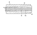
- FIG. 1 is a longitudinal sectional view showing a fixing structure of a composite filament according to an embodiment of the present invention.
- FIG. 2 is a longitudinal sectional view showing a divided wedge body and a sleeve in the identification structure.
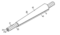
- FIG. 3 is a perspective view showing a composite linear body and a wedge body in the identification structure.
- FIG. 4 is an exploded perspective view showing the composite linear body and the wedge body.
- FIG. 5 is a cross-sectional view showing the identification structure.
- FIG. 6 is an enlarged view showing a main part of the identification wearing structure.
- FIG. 7 is an explanatory diagram showing the relationship between the surface roughness, the wedge length, and the fixing efficiency in the identification structure.
- FIG. 1 is a longitudinal sectional view showing a fixing structure of a composite linear body according to an embodiment of the present invention
- FIG. 2 is a longitudinal sectional view showing a split wedge body and a sleeve in the identification wearing structure
- FIG. 3 is a composite in the identification wearing structure.
- FIG. 4 is an exploded perspective view showing the composite linear body and the wedge body
- FIG. 5 is a cross-sectional view showing the identification wearing structure
- FIG. 6 is a main part of the identification wearing structure. It is an enlarged view shown.
- the axial direction indicates the extending (length) direction of the composite linear body 20.
- the composite linear body terminal fixing structure 10 is composed of a composite linear body 20 in which continuous fibers are composited with a resin material and formed into a stranded wire shape, and a wedge 30 made of a metal material covering the composite linear body 20; And a metal sleeve 50 provided on the outer peripheral side of the wedge body 30.
- tensile force acts from the left direction in FIG. 1, and a right end part is a free end.
- the small diameter side of the wedge body 30 is referred to as a leading end portion, and the large diameter side of the fixed side is referred to as a rear end portion.
- the composite filament 20 has a structure in which a plurality of strands 21 are twisted together.
- the strand 21 is mainly composed of carbon fiber (continuous fiber) and matrix resin (typically thermosetting resin such as epoxy resin).
- a composite wire body 20 having a 1 ⁇ 7 twist structure with an outer diameter of 15.2 mm is formed by twisting six side strands 21b around the core strand 21a as the strand 21. It is configured. Both the core strands 21a and the side strands 21b have a diameter of 5.1 mm.
- the angle between the core strand 21a and the side strand 21b, that is, the twist angle is typically 9 °, and the twist angle is preferably 18 ° or less.
- the inner diameter of the wedge body 30 is determined by the shape of the composite striate body 20 which is a fixing body. Therefore, it is necessary to ensure a sufficient length in order to obtain sufficient fixing efficiency with a pressure that does not cause the composite filament 20 to be crushed.
- the specific length is determined based on one pitch at which the side wire 21b returns to the same position in the circumferential direction. The determination process will be described later.
- the wedge body 30 is formed in a hollow truncated cone shape by combining the divided wedge bodies 40 divided into two in the circumferential direction.
- the split wedge body 40 has a semi-cylindrical main body 41 and an uneven portion 42 a that is provided on the inner wall surface (engagement portion) 42 of the main body 41 and fits with the outer shape of the composite linear body 20.
- the concavo-convex portion 42a has concavo-convex portions obtained by external transfer of the strands 21 constituting the composite linear body 20, and has a so-called rope shape.
- fine irregularities 42b are formed on the inner wall surface as shown in FIG.
- the fine irregularities 42b have an effect of increasing the frictional force in the cross-sectional direction of the composite linear body 20 that is easily deformed, while increasing the contact area with each strand 21 of the composite linear body 20.
- the fine unevenness 42b realizes high gripping force and stable fixing over a long period of time.
- FIG. 7 shows the surface roughness, wedge length, fixing load, fixing efficiency, breaking condition of the composite filament 20 when the tensile test was performed with the fixing structure with the wedge body when the surface roughness and the wedge length were changed. , Shows the relationship with evaluation.
- Fixing efficiency is the ratio between the fixing load and the standard breaking load of the composite filament. In the evaluation, a case where the fixing efficiency exceeds 75% is evaluated as “Good”.
- the surface roughness Rz (ten-point average roughness) of the inner surface forming the fine irregularities 42b is preferably 60 to 500 ⁇ m, and the fine irregularities 42b having an appropriate size are formed, so that the frictional force is increased as described above. A high fixing load was obtained.
- One pitch of the composite filament 20 is 209 mm.
- 150 mm, 210 mm, and 280 mm were acceptable.
- the composite linear body 20 was damaged by the side pressure due to the tightening of the wedge body 30, and thus it was broken at a low fixing load.
- the friction area becomes large, and thus a higher fixing load was obtained.
- it exceeds 280 mm corresponding to 134% of one pitch the practicality is poor. As a result of this test, it was found that 72% to 134% of one pitch is appropriate.
- a split surface 43 is formed on the end surface in the circumferential direction of the main body 41.
- a diameter-expanding portion 44 that increases in diameter as it approaches the mouth is provided on the tip side.
- the wedge body 30 has a split structure as described above, the wedge body 30 can be attached to an arbitrary position of the composite linear body 20, and after the installation, the entire circumference of the composite linear body 20 is covered and is substantially truncated cone.
- the outer shape of the shape is substantially truncated cone.
- the split wedge body 40 is formed as follows. In other words, 3D CAD data based on the composite wire body having the same structure as the composite wire body 20 having the 1 ⁇ 7 twisted structure having the outer diameter of 15.2 mm described above is created, or the external shape is scanned by a 3D scanner or the like. To data. A matrix is created from this data. A sand mold is formed from the mother mold, and the divided wedge body 40 is manufactured by casting. The material is spheroidal graphite cast iron with excellent moldability, strength, toughness, and fatigue strength. Spheroidal graphite cast iron has a high dimensional accuracy because its shrinkage is 1%, which is smaller than 3% of steel.
- gray cast iron in which graphite is flakes has low fatigue strength because fatigue cracks propagate between layers, while spheroidal graphite cast iron has high fatigue strength because fatigue cracks stop with spherical graphite.
- the surface of the inner wall surface of the wedge body is made to have fine irregularities in the range of 60 to 500 ⁇ m in Rz.
- the surface roughness of the inner wall surface 42 of the divided wedge body 40 is measured by using a stylus type surface roughness meter.
- the inner surface of the split wedge body 40 specifically has the following twisted ropes.
- the strand-shaped rope formed by the outer shape transfer of the strand 21 is a circular arc having a diameter of 5.1 mm and an angle of 18 ° or less with respect to the core strand 21a. Furthermore, there are fine irregularities 42b on the inner wall surface.
- the concave and convex portion 42a on the inner surface of the divided wedge body 40 has a shape imitating the shape of the composite linear body 20, when the composite linear body 20 is mounted, the composite linear body 20 and the ropes coincide with each other.
- the wedge body 40 that divides the surface rope by the twisted structure of the filament 20 is filled.
- the pair of split wedges 40 are adjacent to each other with the split surfaces 43 facing each other, but a gap S having a predetermined dimension is formed.
- This predetermined dimension is, for example, 3 to 6 mm.
- the wedge body 30 has a structure in which the outer diameter is increased from the front end portion to the rear end portion, and the composite linear body 20 is engaged with the hollow portion.
- the terminal fixing structure 10 of such a composite filament is assembled as follows. That is, the sleeve 50 is passed through the outer periphery of the composite linear body 20. Next, the pair of wedge bodies 40 are fitted into the composite wire body 20 with the tip portions thereof facing the sleeves 50 to form the wedge bodies 30. Then, the sleeve 50 is moved toward the wedge body 30 and fitted.
- the composite wire body 20 acts as follows when the composite wire body 20 is pulled. That is, since the composite filament 20 and the wedge 30 are integrated, the wedge 30 is pulled into the sleeve 50 at the same time as the composite filament 20 is pulled. When the wedge body 30 is pulled into the sleeve 50, the wedge body 30 tightens the composite linear body 20 due to the gradient. By this tightening, the frictional forces of the wedge body 30 and the composite linear body 20 are further increased, and the integration of the two becomes stronger.
- the composite wire body 20 is used as a prototype, and the inner surface of the divided wedge body 40 obtained by the above-described method has irregularities obtained by transferring the outer shape of the wire 21 constituting the composite wire body 20.
- the wedge body 30 is firmly engaged with the composite linear body 20, and a high gripping force can be obtained over a long period of time because no resin cushioning material or the like is used.
- the sleeve 50 is made of a metal material, has a conical hollow internal structure in which the inner diameter expands from the front end portion to the rear end portion, and is formed in a cylindrical shape having a constant outer diameter.
- the expansion angle of the outer diameter of the wedge body 30 is slightly increased with respect to the expansion angle C of the inner diameter of the sleeve 50.
- the side pressure on the mouth side (the tip portion on the side where the tensile force acts) can be reduced, the stress concentration at the mouth can be reduced, and a high gripping force can be obtained.
- the mouth is rounded, or the vicinity of the mouth is tapered (expanded) toward the tip portion side, so the effect is further enhanced.
- the wedge body 30 is a cylindrical, split, simple molded body, it is not particularly necessary to prepare for attachment, and the wedge body 30 can be easily attached to the composite wire body 20 in a short time.
- the inner surface of the wedge body 30 has a shape that fits with the composite linear body 20, the wedge body 30 is naturally fitted to the composite linear body 20 by pressing the wedge body 30 against the composite linear body 20 during the mounting operation. . For this reason, special skill is not required, and a general worker can easily realize a predetermined quality.
- the fixing force is generated not by the compression force by the compression device but by the tightening force by the wedge body 30 and the sleeve 50.
- the composite linear body 20 is firmly tightened by tightening the wedge body 30, and a high fixing force can be exhibited.
- the wedge body 30 is formed in a shape that fits with the outer shape of the composite linear body 20, it only needs to be covered, and the desired quality can be obtained without depending on the work of a skilled worker. And fixing work can be easily performed.
- the wedge body may be divided into three or four.
- various modifications can be made without departing from the scope of the present invention.
Landscapes
- Engineering & Computer Science (AREA)
- General Engineering & Computer Science (AREA)
- Mechanical Engineering (AREA)
- Ropes Or Cables (AREA)
- Reinforcement Elements For Buildings (AREA)
- Manufacturing Of Tubular Articles Or Embedded Moulded Articles (AREA)
Abstract
Priority Applications (10)
| Application Number | Priority Date | Filing Date | Title |
|---|---|---|---|
| CA2976625A CA2976625A1 (fr) | 2015-02-16 | 2015-02-16 | Structure de fixation de terminal pour corps stries composites |
| DE112015006177.0T DE112015006177T5 (de) | 2015-02-16 | 2015-02-16 | Endenbefestigungsanordnung eines Verbunddrahtseils |
| PCT/JP2015/054143 WO2016132437A1 (fr) | 2015-02-16 | 2015-02-16 | Structure de fixation de terminal pour corps striés composites |
| JP2017500156A JPWO2016132437A1 (ja) | 2015-02-16 | 2015-02-16 | 複合線条体の端末定着構造 |
| US14/673,088 US9562321B2 (en) | 2015-02-16 | 2015-03-30 | End fixing structure of composite wire rod |
| DE112015006179.7T DE112015006179T5 (de) | 2015-02-16 | 2015-12-28 | Endenbefestigungsanordnung eines Verbunddrahtseils |
| JP2017500307A JP6482640B2 (ja) | 2015-02-16 | 2015-12-28 | 複合線条体の端末定着構造 |
| CA2976622A CA2976622C (fr) | 2015-02-16 | 2015-12-28 | Structure de fixation de terminal destinee a des corps stries composites |
| PCT/JP2015/086517 WO2016132657A1 (fr) | 2015-02-16 | 2015-12-28 | Structure de fixation de terminal destinée à des corps striés composites |
| US15/676,827 US10240661B2 (en) | 2015-02-16 | 2017-08-14 | End fixing structure of composite wire rod |
Applications Claiming Priority (1)
| Application Number | Priority Date | Filing Date | Title |
|---|---|---|---|
| PCT/JP2015/054143 WO2016132437A1 (fr) | 2015-02-16 | 2015-02-16 | Structure de fixation de terminal pour corps striés composites |
Related Child Applications (1)
| Application Number | Title | Priority Date | Filing Date |
|---|---|---|---|
| US14/673,088 Continuation US9562321B2 (en) | 2015-02-16 | 2015-03-30 | End fixing structure of composite wire rod |
Publications (1)
| Publication Number | Publication Date |
|---|---|
| WO2016132437A1 true WO2016132437A1 (fr) | 2016-08-25 |
Family
ID=56620877
Family Applications (2)
| Application Number | Title | Priority Date | Filing Date |
|---|---|---|---|
| PCT/JP2015/054143 Ceased WO2016132437A1 (fr) | 2015-02-16 | 2015-02-16 | Structure de fixation de terminal pour corps striés composites |
| PCT/JP2015/086517 Ceased WO2016132657A1 (fr) | 2015-02-16 | 2015-12-28 | Structure de fixation de terminal destinée à des corps striés composites |
Family Applications After (1)
| Application Number | Title | Priority Date | Filing Date |
|---|---|---|---|
| PCT/JP2015/086517 Ceased WO2016132657A1 (fr) | 2015-02-16 | 2015-12-28 | Structure de fixation de terminal destinée à des corps striés composites |
Country Status (5)
| Country | Link |
|---|---|
| US (2) | US9562321B2 (fr) |
| JP (2) | JPWO2016132437A1 (fr) |
| CA (2) | CA2976625A1 (fr) |
| DE (2) | DE112015006177T5 (fr) |
| WO (2) | WO2016132437A1 (fr) |
Cited By (1)
| Publication number | Priority date | Publication date | Assignee | Title |
|---|---|---|---|---|
| JPWO2016132657A1 (ja) * | 2015-02-16 | 2017-10-12 | 東京製綱株式会社 | 複合線条体の端末定着構造 |
Families Citing this family (16)
| Publication number | Priority date | Publication date | Assignee | Title |
|---|---|---|---|---|
| US9828724B2 (en) * | 2013-12-02 | 2017-11-28 | Schlage Lock Company Llc | Multi-pass crimp collar for a looped cable |
| USD809907S1 (en) | 2015-02-17 | 2018-02-13 | Tokyo Rope Mfg. Co., Ltd. | Tool for fixing a tension member of composite strand for prestressed concrete reinforcement and post tensioning concrete structure |
| USD814279S1 (en) * | 2015-12-21 | 2018-04-03 | Tokyo Rope Mfg. Co., Ltd. | Tool for fixing a tension member of composite strand for prestressed concrete reinforcement and post tensioning concrete structure |
| USD815940S1 (en) * | 2015-12-21 | 2018-04-24 | Tokyo Rope Mfg. Co., Ltd. | Tool for fixing a tension member of composite strand for prestressed concrete reinforcement and post tensioning concrete structure |
| SE1600315A1 (sv) * | 2016-10-11 | 2018-04-12 | Rolf Bertil Wall Med Firma Airstone Acad | Concrete pre-stressed with fiber reinforced polymers |
| USD873116S1 (en) * | 2017-01-30 | 2020-01-21 | Tokyo Rope Manufacturing Co., Ltd. | Cable clamp shaped with a wave form |
| WO2018167849A1 (fr) * | 2017-03-14 | 2018-09-20 | 東京製綱株式会社 | Coin de fil toronné |
| CN108571566A (zh) * | 2017-03-14 | 2018-09-25 | 东京制纲株式会社 | 绞线楔 |
| US10780817B2 (en) * | 2019-01-08 | 2020-09-22 | Sebastian Wolstencroft | Metal wrapped bungee assembly |
| US11174639B2 (en) * | 2019-02-28 | 2021-11-16 | Post Tensioning Solutions LLC | Anchor block method for reanchoring live tendons |
| US11530112B2 (en) * | 2019-04-24 | 2022-12-20 | Wurtec, Incorporated | Wire rope clamp assembly |
| CN110042686B (zh) * | 2019-05-08 | 2021-07-30 | 淮南矿业(集团)有限责任公司 | 一种尾绳头制作工艺 |
| US11597124B1 (en) * | 2019-05-20 | 2023-03-07 | Gregory Alan Hunsicker | Method of treating post-tensioning strand wedges with induction heating |
| US11577894B2 (en) * | 2020-11-24 | 2023-02-14 | Idea Makers, LLC | Self-binding equipment ties |
| US11982086B2 (en) * | 2020-12-16 | 2024-05-14 | Iowa State University Research Foundation, Inc. | Ultra high-performance concrete bond anchor |
| US11391344B1 (en) * | 2021-03-12 | 2022-07-19 | C. Sherman Johnson Company, Inc. | Swageless cable terminal |
Citations (2)
| Publication number | Priority date | Publication date | Assignee | Title |
|---|---|---|---|---|
| JPH03229042A (ja) * | 1990-01-31 | 1991-10-11 | Tokyo Seiko Co Ltd | 握索用グリッパー |
| JP2001165245A (ja) * | 1999-12-08 | 2001-06-19 | Mitsubishi Electric Corp | 楔式ロープ留め装置 |
Family Cites Families (25)
| Publication number | Priority date | Publication date | Assignee | Title |
|---|---|---|---|---|
| US3163902A (en) * | 1961-07-28 | 1965-01-05 | Malodan As Copenhagen | Rope clamps |
| US3220074A (en) * | 1963-09-03 | 1965-11-30 | Esco Corp | Self-swaging ferrule |
| US3254383A (en) * | 1964-12-28 | 1966-06-07 | Esco Corp | Self-swaging ferrule |
| JPS4512981Y1 (fr) * | 1966-12-27 | 1970-06-04 | ||
| US3676900A (en) * | 1969-04-19 | 1972-07-18 | Ricardo De Valenzuela | System of fixing braided cables and rods subjected to stress |
| US3676899A (en) * | 1971-03-05 | 1972-07-18 | Delbert D Ehlert | Cable shackle |
| DE7127206U (de) | 1971-07-12 | 1971-10-07 | Siemens Ag | Elektrischer Schalter, insbesondere Hochspannungsschalter |
| ES185731Y (es) * | 1972-11-06 | 1974-07-01 | Manufacturas De Acero | Cuna para anclaje de cables en construccion. |
| ES199828Y (es) * | 1974-01-25 | 1975-12-16 | Manufacturas De Acero | Dispositivo para el anclaje de trenzas y cordones de arma- duras de construccion. |
| US4615532A (en) * | 1984-09-14 | 1986-10-07 | The United States Of America As Represented By The Secretary Of Agriculture | Locking balls for logging carriage |
| FR2586076B1 (fr) * | 1985-08-12 | 1987-12-04 | Freyssinet Int Stup | Perfectionnements aux mors tronconiques d'ancrage pour cables et a leurs procedes de fabrication |
| JPH0512981Y2 (fr) | 1987-12-08 | 1993-04-06 | ||
| JPH01272889A (ja) | 1988-04-22 | 1989-10-31 | Tokyo Seiko Co Ltd | 高強力低伸度繊維を用いた複合撚合体の端末定着方法 |
| US5308026A (en) * | 1992-03-09 | 1994-05-03 | Esmet, Inc. | Midline cable clamp construction |
| DE69311302T2 (de) * | 1993-03-26 | 1998-01-08 | Fuji Valve | Verfahren zur Oberflächenbehandlung eines Ventilatorstössels |
| JPH08237840A (ja) | 1995-02-24 | 1996-09-13 | Tohoku Electric Power Co Inc | 緩衝スリーブおよびこれを用いた撚合せ電線の引留端部 |
| JP2003105551A (ja) * | 2001-09-28 | 2003-04-09 | Polyplastics Co | プラスチックメッキ品の製造方法 |
| JP4818649B2 (ja) | 2005-07-06 | 2011-11-16 | 吉田プラ工業株式会社 | 化粧料容器 |
| CN102482845B (zh) * | 2009-08-12 | 2014-11-12 | 东京制纲株式会社 | 用于纤维增强塑料线绳体的端部锚固结构及方法 |
| GB2474861A (en) * | 2009-10-28 | 2011-05-04 | Paradigm B V | Wedging clamp for cable end |
| CA2785362C (fr) * | 2009-12-23 | 2018-04-17 | Geotech Pty Ltd | Systeme d'ancrage |
| WO2014188469A1 (fr) * | 2013-05-20 | 2014-11-27 | 極東鋼弦コンクリート振興株式会社 | Dispositif d'ancrage pour filament en plastique renforcé par des fibres |
| US9828724B2 (en) * | 2013-12-02 | 2017-11-28 | Schlage Lock Company Llc | Multi-pass crimp collar for a looped cable |
| JP5697292B1 (ja) * | 2014-02-18 | 2015-04-08 | Rtb株式会社 | ロープ装着具 |
| WO2016132437A1 (fr) * | 2015-02-16 | 2016-08-25 | 東京製綱株式会社 | Structure de fixation de terminal pour corps striés composites |
-
2015
- 2015-02-16 WO PCT/JP2015/054143 patent/WO2016132437A1/fr not_active Ceased
- 2015-02-16 JP JP2017500156A patent/JPWO2016132437A1/ja active Pending
- 2015-02-16 DE DE112015006177.0T patent/DE112015006177T5/de not_active Ceased
- 2015-02-16 CA CA2976625A patent/CA2976625A1/fr not_active Abandoned
- 2015-03-30 US US14/673,088 patent/US9562321B2/en not_active Expired - Fee Related
- 2015-12-28 CA CA2976622A patent/CA2976622C/fr active Active
- 2015-12-28 JP JP2017500307A patent/JP6482640B2/ja not_active Expired - Fee Related
- 2015-12-28 WO PCT/JP2015/086517 patent/WO2016132657A1/fr not_active Ceased
- 2015-12-28 DE DE112015006179.7T patent/DE112015006179T5/de not_active Withdrawn
-
2017
- 2017-08-14 US US15/676,827 patent/US10240661B2/en active Active
Patent Citations (2)
| Publication number | Priority date | Publication date | Assignee | Title |
|---|---|---|---|---|
| JPH03229042A (ja) * | 1990-01-31 | 1991-10-11 | Tokyo Seiko Co Ltd | 握索用グリッパー |
| JP2001165245A (ja) * | 1999-12-08 | 2001-06-19 | Mitsubishi Electric Corp | 楔式ロープ留め装置 |
Cited By (2)
| Publication number | Priority date | Publication date | Assignee | Title |
|---|---|---|---|---|
| JPWO2016132657A1 (ja) * | 2015-02-16 | 2017-10-12 | 東京製綱株式会社 | 複合線条体の端末定着構造 |
| US10240661B2 (en) | 2015-02-16 | 2019-03-26 | Tokyo Rope Mfg. Co., Ltd. | End fixing structure of composite wire rod |
Also Published As
| Publication number | Publication date |
|---|---|
| DE112015006177T5 (de) | 2017-11-02 |
| US9562321B2 (en) | 2017-02-07 |
| CA2976622C (fr) | 2019-08-27 |
| JP6482640B2 (ja) | 2019-03-13 |
| CA2976622A1 (fr) | 2016-08-25 |
| US20160237615A1 (en) | 2016-08-18 |
| WO2016132657A1 (fr) | 2016-08-25 |
| JPWO2016132437A1 (ja) | 2017-08-10 |
| JPWO2016132657A1 (ja) | 2017-10-12 |
| US10240661B2 (en) | 2019-03-26 |
| DE112015006179T5 (de) | 2017-11-09 |
| CA2976625A1 (fr) | 2016-08-25 |
| US20170343078A1 (en) | 2017-11-30 |
Similar Documents
| Publication | Publication Date | Title |
|---|---|---|
| WO2016132437A1 (fr) | Structure de fixation de terminal pour corps striés composites | |
| JP5514966B1 (ja) | 繊維強化プラスチック製線条体の定着具 | |
| CA2769575C (fr) | Structure et procede pour fixer un terminal de corps lineaire realise en matiere plastique renforcee par des fibres | |
| CN109797910B (zh) | 一种frp筋锚固用夹片、加工方法及锚固方法 | |
| CN101967867A (zh) | 通用型碳纤维筋夹片式锚具 | |
| Han et al. | Experimental research on mechanical properties of transverse enhanced and high-temperature-resistant CFRP tendons for prestressed structure | |
| US11268280B2 (en) | Anchorage of continuous fiber-reinforced polymer strands | |
| JPWO2015083214A1 (ja) | ロープの端末定着方法および端末定着具付きロープ、ロープの端末定着方法に用いる端末金具 | |
| CN107708948B (zh) | 连续纤维增强材料张紧装置、连续纤维增强材料的张紧方法及楔体 | |
| CN116290576B (zh) | 自应力frp筋锚固系统及锚固方法 | |
| CN104126045A (zh) | 将力导入由多个纤维增强的塑料扁带薄片制成的受拉构件的装置 | |
| CN210529517U (zh) | 一种分体式预应力碳纤维板锚具 | |
| JP6339486B2 (ja) | 緊張材の接続具及び定着具 | |
| CN104963286B (zh) | 一种释放套箍作用的frp拉索锚固装置及其安装方法 | |
| CN204531181U (zh) | 复合线状体的末端固定结构 | |
| CN201943260U (zh) | 通用型碳纤维筋夹片式锚具 | |
| JP7327158B2 (ja) | 定着具 | |
| JP2020153187A (ja) | 繊維強化プラスチック製線条体の端末定着構造および方法,ならびに繊維強化プラスチック製線条体用緩衝材 | |
| JP6022997B2 (ja) | 緊張材の定着体及び引張部材 | |
| CN105887699A (zh) | 复合线状体的末端固定结构 | |
| JP3510356B2 (ja) | 高強力繊維複合緊張材の端末定着部形成方法 | |
| CN102251474A (zh) | 应用于纤维增强复合材料筋拉索的摩擦式锚具 | |
| JP2006176957A (ja) | 高張力繊維複合緊張材の定着方法及びその定着構造 | |
| CN114214938B (zh) | 一种碳纤维拉索的锚固强度提升方法 | |
| CN103591215B (zh) | 用于碳纤维复合材料电缆芯的联接锚固装置 |
Legal Events
| Date | Code | Title | Description |
|---|---|---|---|
| 121 | Ep: the epo has been informed by wipo that ep was designated in this application |
Ref document number: 15882541 Country of ref document: EP Kind code of ref document: A1 |
|
| ENP | Entry into the national phase |
Ref document number: 2017500156 Country of ref document: JP Kind code of ref document: A |
|
| ENP | Entry into the national phase |
Ref document number: 2976625 Country of ref document: CA |
|
| WWE | Wipo information: entry into national phase |
Ref document number: 112015006177 Country of ref document: DE |
|
| 122 | Ep: pct application non-entry in european phase |
Ref document number: 15882541 Country of ref document: EP Kind code of ref document: A1 |