WO2016132496A1 - Climatiseur - Google Patents
Climatiseur Download PDFInfo
- Publication number
- WO2016132496A1 WO2016132496A1 PCT/JP2015/054500 JP2015054500W WO2016132496A1 WO 2016132496 A1 WO2016132496 A1 WO 2016132496A1 JP 2015054500 W JP2015054500 W JP 2015054500W WO 2016132496 A1 WO2016132496 A1 WO 2016132496A1
- Authority
- WO
- WIPO (PCT)
- Prior art keywords
- unit
- control unit
- change
- air
- indoor units
- Prior art date
- Legal status (The legal status is an assumption and is not a legal conclusion. Google has not performed a legal analysis and makes no representation as to the accuracy of the status listed.)
- Ceased
Links
Images


Classifications
-
- F—MECHANICAL ENGINEERING; LIGHTING; HEATING; WEAPONS; BLASTING
- F24—HEATING; RANGES; VENTILATING
- F24F—AIR-CONDITIONING; AIR-HUMIDIFICATION; VENTILATION; USE OF AIR CURRENTS FOR SCREENING
- F24F11/00—Control or safety arrangements
- F24F11/70—Control systems characterised by their outputs; Constructional details thereof
- F24F11/72—Control systems characterised by their outputs; Constructional details thereof for controlling the supply of treated air, e.g. its pressure
- F24F11/74—Control systems characterised by their outputs; Constructional details thereof for controlling the supply of treated air, e.g. its pressure for controlling air flow rate or air velocity
-
- F—MECHANICAL ENGINEERING; LIGHTING; HEATING; WEAPONS; BLASTING
- F24—HEATING; RANGES; VENTILATING
- F24F—AIR-CONDITIONING; AIR-HUMIDIFICATION; VENTILATION; USE OF AIR CURRENTS FOR SCREENING
- F24F11/00—Control or safety arrangements
- F24F11/70—Control systems characterised by their outputs; Constructional details thereof
- F24F11/72—Control systems characterised by their outputs; Constructional details thereof for controlling the supply of treated air, e.g. its pressure
- F24F11/74—Control systems characterised by their outputs; Constructional details thereof for controlling the supply of treated air, e.g. its pressure for controlling air flow rate or air velocity
- F24F11/77—Control systems characterised by their outputs; Constructional details thereof for controlling the supply of treated air, e.g. its pressure for controlling air flow rate or air velocity by controlling the speed of ventilators
-
- F—MECHANICAL ENGINEERING; LIGHTING; HEATING; WEAPONS; BLASTING
- F24—HEATING; RANGES; VENTILATING
- F24F—AIR-CONDITIONING; AIR-HUMIDIFICATION; VENTILATION; USE OF AIR CURRENTS FOR SCREENING
- F24F2110/00—Control inputs relating to air properties
- F24F2110/30—Velocity
-
- Y—GENERAL TAGGING OF NEW TECHNOLOGICAL DEVELOPMENTS; GENERAL TAGGING OF CROSS-SECTIONAL TECHNOLOGIES SPANNING OVER SEVERAL SECTIONS OF THE IPC; TECHNICAL SUBJECTS COVERED BY FORMER USPC CROSS-REFERENCE ART COLLECTIONS [XRACs] AND DIGESTS
- Y02—TECHNOLOGIES OR APPLICATIONS FOR MITIGATION OR ADAPTATION AGAINST CLIMATE CHANGE
- Y02B—CLIMATE CHANGE MITIGATION TECHNOLOGIES RELATED TO BUILDINGS, e.g. HOUSING, HOUSE APPLIANCES OR RELATED END-USER APPLICATIONS
- Y02B30/00—Energy efficient heating, ventilation or air conditioning [HVAC]
- Y02B30/70—Efficient control or regulation technologies, e.g. for control of refrigerant flow, motor or heating
Definitions
- the present invention relates to an air conditioner capable of automatically controlling a blower so that a predetermined air volume is obtained when it deviates from an initial static wind pressure value during operation.
- a damper may be installed in the duct to adjust to a predetermined air volume. In the above-described method, even if the required air volume decreases, the power load of the blower hardly changes, so that energy loss occurs.
- the present invention is for solving the above-described problems, and in the case of an installation configuration in which a plurality of indoor units are connected to a single duct, the entire air volume can be efficiently reduced without measuring static pressure and air volume.
- An object is to provide an air conditioner to be controlled.
- An air conditioner includes a plurality of indoor units each having a fan and a control unit, and a duct connected to the plurality of indoor units and sending out air conditioned by the plurality of indoor units,
- One of the plurality of indoor units is a master unit, the other is a slave unit, and the control unit of the master unit and the control unit of the slave unit each determine the amount of air blown by the own unit, and the control unit of the master unit is , Taking in the blast volume of the slave unit, obtaining the overall blast volume of the plurality of indoor units including its own unit, determining whether the overall blast volume is excessive or insufficient with respect to the reference air volume, When it is determined that there is a shortage, the fan of the indoor unit that can be driven most efficiently among the plurality of indoor units including the own unit is selected, and a change in the rotation speed of the fan is commanded.
- the indoor unit fan that can be driven most efficiently among all the indoor units is selected and the rotation speed of the fan is instructed, it approaches the predetermined air volume.
- the entire air volume can be efficiently controlled without measuring the static pressure and the air volume.
- FIG. 1 is a diagram illustrating an installation mode of indoor units 1, 2, and 3 of an air conditioner 100 according to Embodiment 1 of the present invention.
- Two or more indoor units 1, 2, and 3 of the air conditioner 100 shown in FIG. Here, a case where three units are installed will be described as an example.
- the indoor units 1, 2, and 3 are connected to the duct 4, and the indoor units 1, 2, and 3 are communicably connected via the communication line 5.
- the communication line 5 may be wired or wireless.
- one of the indoor units 1, 2, and 3 is set as a master unit, and other indoor units other than the master unit are set as slave units.
- the indoor unit 1 is assumed to be a master unit.
- the indoor units 2 and 3 are set as slave units.
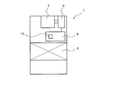
- FIG. 2 is a schematic diagram illustrating the configuration of the indoor unit 1 of the air conditioner 100 according to Embodiment 1 of the present invention.
- the indoor unit 1 controls a heat exchanger 6 that exchanges heat between refrigerant and room air, a fan 7 that causes room air to flow out into the duct 4, a motor 8 that imparts rotational driving force to the fan 7, and the motor 8.
- An inverter 9 and a microcomputer 10 that issues a control command to the inverter 9 are provided.
- the indoor units 2 and 3 have the same configuration as the indoor unit 1. Therefore, the configuration of only the indoor unit 1 will be described.
- the indoor unit 1 of the air conditioner 100 harmonizes the air by the heat exchanger 6, drives the fan 7 by the motor 8 controlled by the inverter 9 having the microcomputer 10, and conditioned air (outdoors) Blow out air).
- the microcomputer 10 included in the indoor unit 1 of the air conditioner 100 stores fan characteristics such as the rotational speed of the fan 7, the air volume, the static pressure, and the current.
- the inverter 9 equipped with the microcomputer 10 includes a mechanism that can detect the rotation speed and current of the fan 7, and can change the rotation speed of the fan 7 by changing the current to the motor 8 that drives the fan 7.
- the microcomputers 10 of the indoor units 1, 2 and 3 can communicate with each other via the communication line 5.
- the microcomputer 10 provided in the indoor unit 1 constitutes a control unit of the master unit of the air conditioner 100.
- the microcomputer 10 with which the indoor units 2 and 3 are provided comprises the control part of the subunit
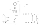
- FIG. 3 is a refrigerant circuit diagram illustrating a schematic configuration of the air conditioner 100 according to Embodiment 1 of the present invention.
- the microcomputer 10 switches the four-way valve 103 to the cooling operation, the refrigerant is compressed by the compressor 101 to become a high-temperature and high-pressure gas refrigerant, and flows into the outdoor heat exchanger 104 through the four-way valve 103.
- the high-temperature and high-pressure gas refrigerant that has flowed into the outdoor heat exchanger 104 undergoes heat exchange (heat radiation) with outdoor air that passes through the outdoor heat exchanger 104 and flows out as high-pressure liquid refrigerant.
- the high-pressure liquid refrigerant that has flowed out of the outdoor heat exchanger 104 is depressurized by the capillary tube 105 and the electronically controlled expansion valve 106, becomes a low-pressure gas-liquid two-phase refrigerant, and flows into the heat exchanger 6.
- the gas-liquid two-phase refrigerant that has flowed into the heat exchanger 6 is heat-exchanged with the room air passing through the heat exchanger 6, cools the room air, and is sucked into the compressor 101 as a low-temperature and low-pressure gas refrigerant. .
- the refrigerant is compressed by the compressor 101 in the same manner as described above to become a high-temperature and high-pressure gas refrigerant and flows into the heat exchanger 6 through the four-way valve 103.
- the high-temperature and high-pressure gas refrigerant that has flowed into the heat exchanger 6 is heat-exchanged with the room air that passes through the heat exchanger 6, and warms the room air to become a high-pressure liquid refrigerant.
- the high-pressure liquid refrigerant that has flowed out of the heat exchanger 6 is depressurized by the electronic control type expansion valve 106 and the capillary tube 105, becomes a low-pressure gas-liquid two-phase refrigerant, and flows into the outdoor heat exchanger 104.
- the low-pressure gas-liquid two-phase refrigerant that has flowed into the outdoor heat exchanger 104 is heat-exchanged with outdoor air that passes through the outdoor heat exchanger 104 and is sucked into the compressor 101 as a low-temperature and low-pressure gas refrigerant.
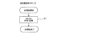
- FIG. 4 is a diagram showing a flow during a trial operation of the indoor units 1, 2, and 3 of the air conditioner 100 according to Embodiment 1 of the present invention. First, the control flow at the time of trial operation of the indoor units 1, 2, and 3 of the air conditioner 100 will be described with reference to FIG.
- step S1 the microcomputer 10 of each indoor unit 1, 2, 3 operates at a predetermined air volume Q0 in which the air volume of the duct 4 is constant during a trial operation such as construction, and the current value A0 of the fan 7 and rotation at that time
- the number N0 is stored in the microcomputer 10.
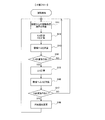
- FIG. 5 is a diagram showing a flow during operation of the master unit of the air-conditioning apparatus 100 according to Embodiment 1 of the present invention. Next, the master unit control flow during operation of the master unit set in the indoor unit 1 of the air conditioner 100 will be described with reference to FIG.
- step ST ⁇ b> 1 the microcomputer 10 of the parent device transmits a calculation command for the air flow rate Q from the parent device to the child device through the communication line 5 during the operation start.
- the master unit also calculates the air flow rate Q.
- the air flow rate Q is calculated by measuring the operating current value A and the operating rotational speed N and using the relationship stored in the microcomputer 10.
- step ST ⁇ b> 2 the microcomputer 10 of the parent device receives the data of the blowing amount Q of the child device through the communication line 5.
- step ST3 when the microcomputer 10 of the master unit receives the information on the air flow rate Q from the slave unit via the communication line 5, the predetermined air volume Q0 (reference air volume) that makes the duct 4 a constant air volume and all the indoor units 1 and 2 are set.
- step ST4 the microcomputer 10 of the master unit determines whether or not there is an excess / shortage amount ⁇ Q of the air flow. If the excess air shortage amount ⁇ Q exists in step ST4 (YES), the process proceeds to step ST5. When there is no excess air shortage ⁇ Q (NO), the process proceeds to step ST1.
- step ST5 the microcomputer 10 of the master unit sends a command to the slave unit to calculate the change amount ⁇ A between the current value A1 and the current value A when the blower amount is changed by the excess or shortage amount ⁇ Q. Send by.
- the master unit also calculates the change amount ⁇ A.
- step ST ⁇ b> 6 the microcomputer 10 of the parent device receives the change amount ⁇ A from the child device via the communication line 5.
- step ST7 the microcomputer 10 of the parent device compares the change amount ⁇ A of each child device transmitted through the communication line 5 with the change amount ⁇ A of the parent device.
- step ST8 the microcomputer 10 of the master unit performs the most efficient driving (the amount of current can be changed most efficiently) for the indoor unit that satisfies the amount of ventilation excess / deficiency ⁇ Q by the change amount ⁇ A.
- a command for changing the rotational speed N of the fan 7 by the amount of change ⁇ A is transmitted through the communication line 5.
- the most efficient driving by the change amount ⁇ A means that when the excess air shortage amount ⁇ Q is insufficient, the air amount is increased to increase the current value by ⁇ A in the indoor unit having the minimum change amount ⁇ A, This refers to minimizing the increase in the total amount of current.
- step ST9 the microcomputer 10 of the parent device determines whether or not there is a command to change the rotational speed N of the fan 7. If there is a command to change the rotation speed N of the fan 7 in step ST9 (YES), the process proceeds to step ST10. If there is no command to change the rotational speed N of the fan 7 (NO), the process proceeds to step ST1.
- step ST10 the microcomputer 10 of the master unit changes the rotational speed N of the fan 7 by the amount of change of the change amount ⁇ A by controlling the inverter 9 in accordance with a command for changing the rotational speed N of the fan 7. From step ST10, the process returns to step ST1.
- FIG. 6 is a diagram showing a flow during operation of the slave unit of the air conditioner 100 according to Embodiment 1 of the present invention.
- movement of the indoor units 2 and 3 of the air conditioner 100 is demonstrated using FIG.
- step SH1 the microcomputer 10 of the slave unit receives an information transmission command (command of step ST1) from the master unit via the communication line 5 after the start of normal operation.
- step SH ⁇ b> 2 the microcomputer 10 of the slave unit measures the operating current value A and the operating rotational speed N for the indoor units 2 and 3, and calculates the air flow rate Q using the relationship stored in the microcomputer 10.
- step SH ⁇ b> 3 the microcomputer 10 of the child device transmits the calculated air flow rate Q to the parent device via the communication line 5.
- step SH4 the microcomputer 10 of the slave unit changes the current value A1 when the air flow rate is changed by the air flow excess / shortage amount ⁇ Q calculated from the predetermined air flow rate Q0 and the entire air flow rate Q via the communication line 5. It is determined whether or not there is a command (command in step ST5) for calculating the amount of change ⁇ A from the current value A. If there is a command to calculate the change amount ⁇ A in step SH4 (YES), the process proceeds to step SH5. If there is no command to calculate the change amount ⁇ A (NO), the process proceeds to step SH1.
- step SH5 the microcomputer 10 of the slave unit calculates the change amount ⁇ A from the difference between the current value A1 and the current value A when the air flow rate is changed by the air flow excess / deficiency amount ⁇ Q.
- step SH6 the microcomputer 10 of the child device transmits the change amount ⁇ A to the parent device via the communication line 5.
- step SH7 the microcomputer 10 of the slave unit determines whether or not there is a command for changing the rotational speed N of the fan 7 (command in step ST8) via the communication line 5. If there is a command to change the rotational speed N of the fan 7 in step SH7 (YES), the process proceeds to step SH8. If there is no command to change the rotational speed N of the fan 7 (NO), the process proceeds to step SH1.
- step SH8 the microcomputer 10 of the slave unit changes the rotational speed N of the fan 7 by the amount of change ⁇ A by controlling the inverter 9 in accordance with a command to change the rotational speed N of the fan 7 via the communication line 5. To do. From step SH8, the process returns to step SH1.
- FIG. 5 and FIG. 6 the flow of FIG. 5 and FIG. 6 is executed during operation, so that the microcomputer 10 of the slave unit calculates the air flow rate Q in accordance with the command of the microcomputer 10 of the master unit and transfers it to the microcomputer 10 of the master unit. It transmits by the communication line 5.
- the microcomputer 10 of the master unit that has received the air flow rate Q from the microcomputer 10 of the slave unit via the communication line 5 uses the air flow excess / shortage amount ⁇ Q from the predetermined air volume Q0 and the total air volume Q of all the indoor units 1, 2, and 3.
- the microcomputer 10 of the master unit determines that there is an excess / shortage amount ⁇ Q of the blower, it issues a command to the microcomputer 10 of the slave unit via the communication line 5 to change the blower amount by the excess / shortage amount ⁇ Q of the slave unit.
- the amount of change ⁇ A between the current value A1 and the current value A is calculated and transmitted to the microcomputer 10 of the parent machine via the communication line 5.
- the change amount ⁇ A is also calculated by the microcomputer 10 of the parent machine.
- the microcomputer 10 of the master unit compares the transmitted change ⁇ A of the master unit and each slave unit, and can be driven most efficiently by the change amount ⁇ A of all indoor units 1, 2, and 3 of the master unit and the slave units.
- a command to control the rotational speed N of the fan 7 is transmitted through the communication line 5 to a simple indoor unit.
- the microcomputer 10 of the indoor unit that has received the command changes the rotational speed of the fan 7 by the change amount of the change amount ⁇ A. By repeating this, the air flow rate Q can be adjusted to a predetermined air flow rate Q0.
- the first embodiment it is possible to adjust the entire air flow rate Q so that the air flow rate Q0 (set value) becomes a predetermined air volume even if the air path pressure loss such as filter clogging increases or decreases during operation.
- the information of the indoor units 1, 2, and 3 in operation is communicated among a plurality of indoor units, and the microcomputer 10 of the master unit is the most efficient indoor unit that can be driven by the change amount ⁇ A among all the indoor units.
- the current value is efficiently changed to approach a predetermined air volume Q 0 (set value), and a plurality of indoor units 1, 2 for a single duct 4. 3 can be efficiently controlled without measuring static pressure and air volume.
- the master unit since the master unit transmits a command to the slave unit and performs overall control, it is possible to achieve adjustment of the air volume and optimization of the power load in the plurality of indoor units 1, 2, and 3 as a whole.
- the change in the current value is the least increased.
- the current value is efficiently changed so as to decrease a lot, and can be brought close to a predetermined air volume Q0 (set value).
- the microcomputer 10 of the parent device when it is determined that there is an excess or deficiency, the microcomputer 10 of the parent device can be driven most efficiently among the plurality of indoor units 1, 2, and 3 including the own device.
- the fan 7 of the indoor unit is selected, and the change of the rotation speed of the fan 7 is instructed.
- Q0 set value
- a plurality of indoor units 1 In the case of the installation configuration in which two and three are connected, the entire air volume can be efficiently controlled without measuring the static pressure and the air volume.
- the microcomputer 10 of the slave unit obtains the air flow rate Q of its own unit based on a command from the microcomputer 10 of the master unit and transmits it to the microcomputer 10 of the master unit. According to this, comprehensive control by the microcomputer 10 of the master unit can be realized, and adjustment of the air volume and optimization of the power load in the plurality of indoor units 1, 2, and 3 can be achieved.
- the microcomputer 10 of the master unit acquires the change amount ⁇ A of the current of the slave unit, and is the indoor unit that can be driven most efficiently based on the change amount ⁇ A of the current of the plurality of indoor units 1, 2, and 3 including its own unit
- the fan 7 is selected, and a change in the rotational speed of the fan 7 is commanded so as to satisfy the excess / deficiency air volume.
- Q0 set value
- the entire air volume can be controlled efficiently without measuring the static pressure and the air volume.
- the microcomputer 10 of the master unit obtains the change amount ⁇ A of the current of the slave unit, and is the smallest change amount ⁇ A of the current among the change amounts ⁇ A of the plurality of indoor units 1, 2, and 3 including the self unit.
- the indoor unit is selected as the fan of the indoor unit that can be driven most efficiently, and an increase in the number of rotations of the fan 7 is commanded so as to satisfy the insufficient air volume. According to this, in the case of an installation configuration in which a plurality of indoor units 1, 2, 3 are connected to a single duct 4 while the current value efficiently increases to the minimum necessary and approaches the predetermined air volume Q 0 (set value). In addition, the entire air volume can be efficiently controlled without measuring the static pressure and the air volume.
- the slave microcomputer 10 obtains the current change amount ⁇ A of the own machine based on a command from the master microcomputer 10 and transmits it to the master microcomputer 10. According to this, comprehensive control by the microcomputer 10 of the master unit can be realized, and adjustment of the air volume and optimization of the power load in the plurality of indoor units 1, 2, and 3 can be achieved.
Landscapes
- Engineering & Computer Science (AREA)
- Physics & Mathematics (AREA)
- Fluid Mechanics (AREA)
- Chemical & Material Sciences (AREA)
- Combustion & Propulsion (AREA)
- Mechanical Engineering (AREA)
- General Engineering & Computer Science (AREA)
- Air Conditioning Control Device (AREA)
Abstract
Priority Applications (3)
| Application Number | Priority Date | Filing Date | Title |
|---|---|---|---|
| PCT/JP2015/054500 WO2016132496A1 (fr) | 2015-02-18 | 2015-02-18 | Climatiseur |
| JP2017500209A JP6320617B2 (ja) | 2015-02-18 | 2015-02-18 | 空気調和機 |
| GB1711447.1A GB2552896B (en) | 2015-02-18 | 2015-02-18 | Air-conditioning apparatus |
Applications Claiming Priority (1)
| Application Number | Priority Date | Filing Date | Title |
|---|---|---|---|
| PCT/JP2015/054500 WO2016132496A1 (fr) | 2015-02-18 | 2015-02-18 | Climatiseur |
Publications (1)
| Publication Number | Publication Date |
|---|---|
| WO2016132496A1 true WO2016132496A1 (fr) | 2016-08-25 |
Family
ID=56692498
Family Applications (1)
| Application Number | Title | Priority Date | Filing Date |
|---|---|---|---|
| PCT/JP2015/054500 Ceased WO2016132496A1 (fr) | 2015-02-18 | 2015-02-18 | Climatiseur |
Country Status (3)
| Country | Link |
|---|---|
| JP (1) | JP6320617B2 (fr) |
| GB (1) | GB2552896B (fr) |
| WO (1) | WO2016132496A1 (fr) |
Cited By (2)
| Publication number | Priority date | Publication date | Assignee | Title |
|---|---|---|---|---|
| JP2021009021A (ja) * | 2019-04-15 | 2021-01-28 | ダイキン工業株式会社 | 空気調和システム |
| JP2021032444A (ja) * | 2019-08-21 | 2021-03-01 | 株式会社日立産機システム | ファンフィルタユニット監視制御システムおよびファンフィルタユニット監視制御方法 |
Citations (4)
| Publication number | Priority date | Publication date | Assignee | Title |
|---|---|---|---|---|
| JP3004607U (ja) * | 1994-05-25 | 1994-11-22 | 東洋熱工業株式会社 | 空調制御システム |
| JP2003035447A (ja) * | 2001-07-23 | 2003-02-07 | Sanki Eng Co Ltd | 空気調和機の省エネルギシステム |
| JP2012189268A (ja) * | 2011-03-11 | 2012-10-04 | Hitachi Appliances Inc | 空気調和装置 |
| JP2013204859A (ja) * | 2012-03-27 | 2013-10-07 | Toshiba Carrier Corp | コンテナ用空調システム |
Family Cites Families (2)
| Publication number | Priority date | Publication date | Assignee | Title |
|---|---|---|---|---|
| JP3004607B2 (ja) * | 1997-07-01 | 2000-01-31 | ナビタス株式会社 | 転写紙の製造装置 |
| JP2013160446A (ja) * | 2012-02-06 | 2013-08-19 | Daikin Industries Ltd | 外気処理システム |
-
2015
- 2015-02-18 WO PCT/JP2015/054500 patent/WO2016132496A1/fr not_active Ceased
- 2015-02-18 JP JP2017500209A patent/JP6320617B2/ja active Active
- 2015-02-18 GB GB1711447.1A patent/GB2552896B/en active Active
Patent Citations (4)
| Publication number | Priority date | Publication date | Assignee | Title |
|---|---|---|---|---|
| JP3004607U (ja) * | 1994-05-25 | 1994-11-22 | 東洋熱工業株式会社 | 空調制御システム |
| JP2003035447A (ja) * | 2001-07-23 | 2003-02-07 | Sanki Eng Co Ltd | 空気調和機の省エネルギシステム |
| JP2012189268A (ja) * | 2011-03-11 | 2012-10-04 | Hitachi Appliances Inc | 空気調和装置 |
| JP2013204859A (ja) * | 2012-03-27 | 2013-10-07 | Toshiba Carrier Corp | コンテナ用空調システム |
Cited By (4)
| Publication number | Priority date | Publication date | Assignee | Title |
|---|---|---|---|---|
| JP2021009021A (ja) * | 2019-04-15 | 2021-01-28 | ダイキン工業株式会社 | 空気調和システム |
| JP7181477B2 (ja) | 2019-04-15 | 2022-12-01 | ダイキン工業株式会社 | 空気調和システム |
| JP2021032444A (ja) * | 2019-08-21 | 2021-03-01 | 株式会社日立産機システム | ファンフィルタユニット監視制御システムおよびファンフィルタユニット監視制御方法 |
| JP7249240B2 (ja) | 2019-08-21 | 2023-03-30 | 株式会社日立産機システム | ファンフィルタユニット監視制御システムおよびファンフィルタユニット監視制御方法 |
Also Published As
| Publication number | Publication date |
|---|---|
| JP6320617B2 (ja) | 2018-05-09 |
| GB201711447D0 (en) | 2017-08-30 |
| GB2552896B (en) | 2020-07-22 |
| GB2552896A (en) | 2018-02-14 |
| JPWO2016132496A1 (ja) | 2017-08-31 |
Similar Documents
| Publication | Publication Date | Title |
|---|---|---|
| US10989429B2 (en) | Air conditioning system | |
| US9677780B2 (en) | Controller and air conditioning processing system | |
| US9995517B2 (en) | Operation control apparatus of air-conditioning apparatus and air-conditioning apparatus comprising same | |
| JP5182358B2 (ja) | 冷凍装置 | |
| AU2012392673B2 (en) | Air conditioning apparatus | |
| CN102460029B (zh) | 空气调节器及其运行方法 | |
| EP2527754A1 (fr) | Système de commande et procédé de commande de confort et d'économie d'énergie dans un système de conditionnement d'air | |
| AU2012392672B2 (en) | Air conditioning apparatus | |
| CN106765563A (zh) | 空调节能控制方法 | |
| EP3336443A1 (fr) | Système de conditionnement d'air | |
| CN102213470A (zh) | 一种辐射及新风混合空调系统 | |
| JP7181477B2 (ja) | 空気調和システム | |
| CN106765910A (zh) | 空调节能控制方法 | |
| EP1684030B1 (fr) | Procédé de commande d'un système de conditionnement d'air | |
| JP6320617B2 (ja) | 空気調和機 | |
| KR101991561B1 (ko) | 공기 조화 시스템의 제어 방법 및 장치 | |
| JPWO2017212571A1 (ja) | 空調システム及び中継機 | |
| US9464835B2 (en) | Remote software loading for refrigerant system | |
| WO2019215813A1 (fr) | Appareil de climatisation | |
| JP2000186864A (ja) | 電動膨張弁の制御方法 | |
| KR101229345B1 (ko) | 멀티형 공기조화기의 제어방법 | |
| KR20100019162A (ko) | 멀티형 공기조화기 | |
| CN107477683A (zh) | 屋顶式空调器 | |
| KR20240070399A (ko) | Ai 기반 변풍량 공조 송풍기 시스템 | |
| WO2025204751A1 (fr) | Dispositif à cycle frigorifique |
Legal Events
| Date | Code | Title | Description |
|---|---|---|---|
| 121 | Ep: the epo has been informed by wipo that ep was designated in this application |
Ref document number: 15882599 Country of ref document: EP Kind code of ref document: A1 |
|
| ENP | Entry into the national phase |
Ref document number: 2017500209 Country of ref document: JP Kind code of ref document: A |
|
| ENP | Entry into the national phase |
Ref document number: 201711447 Country of ref document: GB Kind code of ref document: A Free format text: PCT FILING DATE = 20150218 |
|
| NENP | Non-entry into the national phase |
Ref country code: DE |
|
| 122 | Ep: pct application non-entry in european phase |
Ref document number: 15882599 Country of ref document: EP Kind code of ref document: A1 |