WO2016132795A1 - 油分濃度計測装置及び油分濃度計測方法 - Google Patents
油分濃度計測装置及び油分濃度計測方法 Download PDFInfo
- Publication number
- WO2016132795A1 WO2016132795A1 PCT/JP2016/051369 JP2016051369W WO2016132795A1 WO 2016132795 A1 WO2016132795 A1 WO 2016132795A1 JP 2016051369 W JP2016051369 W JP 2016051369W WO 2016132795 A1 WO2016132795 A1 WO 2016132795A1
- Authority
- WO
- WIPO (PCT)
- Prior art keywords
- concentration
- oil
- absorbance
- predetermined
- calibration curve
- Prior art date
- Legal status (The legal status is an assumption and is not a legal conclusion. Google has not performed a legal analysis and makes no representation as to the accuracy of the status listed.)
- Ceased
Links
Images



Classifications
-
- G—PHYSICS
- G01—MEASURING; TESTING
- G01N—INVESTIGATING OR ANALYSING MATERIALS BY DETERMINING THEIR CHEMICAL OR PHYSICAL PROPERTIES
- G01N21/00—Investigating or analysing materials by the use of optical means, i.e. using sub-millimetre waves, infrared, visible or ultraviolet light
- G01N21/17—Systems in which incident light is modified in accordance with the properties of the material investigated
- G01N21/25—Colour; Spectral properties, i.e. comparison of effect of material on the light at two or more different wavelengths or wavelength bands
- G01N21/27—Colour; Spectral properties, i.e. comparison of effect of material on the light at two or more different wavelengths or wavelength bands using photo-electric detection ; circuits for computing concentration
- G01N21/274—Calibration, base line adjustment, drift correction
-
- G—PHYSICS
- G01—MEASURING; TESTING
- G01N—INVESTIGATING OR ANALYSING MATERIALS BY DETERMINING THEIR CHEMICAL OR PHYSICAL PROPERTIES
- G01N21/00—Investigating or analysing materials by the use of optical means, i.e. using sub-millimetre waves, infrared, visible or ultraviolet light
- G01N21/17—Systems in which incident light is modified in accordance with the properties of the material investigated
- G01N21/25—Colour; Spectral properties, i.e. comparison of effect of material on the light at two or more different wavelengths or wavelength bands
- G01N21/31—Investigating relative effect of material at wavelengths characteristic of specific elements or molecules, e.g. atomic absorption spectrometry
- G01N21/33—Investigating relative effect of material at wavelengths characteristic of specific elements or molecules, e.g. atomic absorption spectrometry using ultraviolet light
-
- G—PHYSICS
- G01—MEASURING; TESTING
- G01N—INVESTIGATING OR ANALYSING MATERIALS BY DETERMINING THEIR CHEMICAL OR PHYSICAL PROPERTIES
- G01N33/00—Investigating or analysing materials by specific methods not covered by groups G01N1/00 - G01N31/00
- G01N33/26—Oils; Viscous liquids; Paints; Inks
- G01N33/28—Oils, i.e. hydrocarbon liquids
- G01N33/2835—Specific substances contained in the oils or fuels
-
- G—PHYSICS
- G01—MEASURING; TESTING
- G01N—INVESTIGATING OR ANALYSING MATERIALS BY DETERMINING THEIR CHEMICAL OR PHYSICAL PROPERTIES
- G01N33/00—Investigating or analysing materials by specific methods not covered by groups G01N1/00 - G01N31/00
- G01N33/26—Oils; Viscous liquids; Paints; Inks
- G01N33/28—Oils, i.e. hydrocarbon liquids
- G01N33/2894—Oils, i.e. hydrocarbon liquids for metal working or machining
Definitions
- the present invention relates to an apparatus and method for measuring the concentration of oil in a liquid.
- This oil concentration measuring device and oil concentration measuring method is used for industrial cleaning machines that remove organic dirt such as cutting oil, press / punching oil, machine oil, grease, flux, etc. adhering to workpieces. It is suitably used for measuring the concentration of oil contained in the.
- the cleaning liquid used in industrial cleaning machines is mainly hydrocarbon cleaning liquid. Since the hydrocarbon-based cleaning liquid does not contain an ozone-depleting substance or chlorine, it has a feature that it has little influence on the environment and the human body.
- the hydrocarbon-based cleaning liquid can be regenerated by distillation using the difference in boiling point from the oil, and clean steam generated during the regeneration process is washed and dried (hereinafter referred to as “steam cleaning / drying”). It is also possible to use it for " In steam cleaning / drying, the work is stored in a steam cleaning / drying cleaning tank, the surface of the work is cleaned with the steam by introducing the steam into the tank, and then the inside of the tank is rapidly depressurized.
- a workpiece is stored in a liquid cleaning tank in which a hydrocarbon-based cleaning liquid is stored and liquid cleaning is performed, and then steam cleaning and drying are performed for finishing. Rinse with a hydrocarbon-based cleaning liquid may be performed between liquid cleaning and steam cleaning / drying.
- the cleaning ability of hydrocarbon cleaning liquid depends on the oil concentration in the liquid and steam. Also, when the oil concentration in the steam is increased during drying, there is a risk that a stain will remain.
- the oil removed by the distillation regeneration of the hydrocarbon-based cleaning liquid used for the liquid cleaning accumulates in the distillation tank. If it does so, the oil-type density
- boiling refers to heating the residual liquid in the distillation tank while the supply of hydrocarbon-based cleaning liquid to the distillation tank and the supply of steam from the distillation tank to the steam cleaning / drying cleaning tank are stopped. This means that the hydrocarbon-based cleaning liquid in the liquid is evaporated to concentrate the residual oil.
- the timing of simmering and draining oil has been set by manufacturers of industrial cleaning machines according to the type and frequency of use of the oils cleaned by individual industrial cleaning machines.
- the oil concentration in the liquid washing tank is measured, and the timing of boiling and draining oil is changed based on the result.
- Patent Document 1 the absorbance of a cleaning liquid used for cleaning a workpiece is measured using ultraviolet light having a predetermined wavelength in the range of 200 to 380 nm, and the concentration of a known dirt component prepared in advance is measured. It describes that the concentration of a soil component dissolved in the cleaning liquid is obtained based on a calibration curve of absorbance.
- Patent Document 1 further describes a second storage in which the rinsing liquid is stored in order to automatically measure the concentration of the oil remaining in the rinsing liquid for rinsing the workpiece after being cleaned with the cleaning liquid.
- a cleaning device provided with a circulation path for a rinsing liquid that returns from the tank to the second storage tank through a glass cell of an ultraviolet absorptiometer.
- the absorbance of the rinsing liquid that is, the concentration of oil in the rinsing liquid is constantly measured.
- setting and changing the timing of boiling and draining oil in the distillation tank is based on the result of measuring the oil concentration of the hydrocarbon-based cleaning liquid in the liquid cleaning tank, so the oil concentration in the liquid cleaning tank is always automatically If it can be measured automatically, the timing can be set and changed automatically. It is also possible to change the conditions of the cleaning operation based on the concentration of the oil content of the cleaning liquid and perform cleaning under optimum conditions at each time point. For example, since the cleaning efficiency is high when the oil concentration of the cleaning liquid is low, the cleaning is completed in a short time, and when the oil concentration of the cleaning liquid is high, the cleaning efficiency is low, so that the cleaning time can be extended. .
- Patent Document 1 Although the oil concentration is constantly measured for the rinsing liquid, the cleaning liquid cannot always be measured. This is because the concentration of the oil in the cleaning liquid is much wider than that in the case of the rinsing liquid and reaches a maximum of about 20000 ppm. In the apparatus described in Patent Document 1, it is not possible to directly measure a cleaning solution having a high oil concentration exceeding 1000 ppm, and the concentration is reduced to 1000 ppm or less by diluting with an unused cleaning solution as described above. It is necessary to measure it after reducing it. Thus, since the necessity of the dilution operation differs depending on the concentration, it is difficult to always measure the oil concentration of the cleaning liquid with the apparatus of Patent Document 1.
- the oil concentration in the residual liquid in the distillation tank can be automatically measured, the timing of boiling and draining oil can be determined more directly.
- the concentration of oil in the residual liquid in the distillation tank reaches about 50000 ppm. Therefore, automatic measurement of the oil concentration in the distillation tank by the apparatus of Patent Document 1 is more difficult than the case of measuring the oil concentration of the hydrocarbon-based cleaning liquid.
- the problem to be solved by the present invention is to provide an oil concentration measuring device and an oil concentration measuring method that can measure the oil concentration over a wide concentration range, and can be applied to the continuous measurement of the oil concentration. That is.
- An oil concentration measuring apparatus which has been made to solve the above problems, comprises an oil component containing a molecule having a carbon atom polyvalent bond as a main component and a molecule having a carbon atom polyvalent bond.
- a device for measuring the concentration of the oil in the measurement target liquid mixed with a) an absorbance measuring means for measuring an absorbance spectrum in a predetermined wavelength band between 270 and 400 nm at which light absorption is observed for the measurement target liquid; b) Oil concentration determination means for low concentration that obtains the concentration value of the oil based on the absorbance at the predetermined wavelength within the predetermined wavelength band and the first calibration curve indicating the relationship between the concentration of the component and the absorbance at the predetermined wavelength.
- Oil concentration determination means for high concentration to obtain a concentration value; d) comprising an oil concentration determination method selection means for selecting, based on a predetermined standard, a means for determining the oil concentration value from the low concentration oil concentration determination means and the high concentration oil concentration determination means.
- the concentration of oil can be measured by measuring the absorbance of the liquid to be measured within a predetermined wavelength band between 270 and 400 nm. Therefore, an oil component containing a molecule having a polyvalent bond of carbon atoms in a liquid to be measured whose main component is a molecule not having a polyvalent bond of carbon atoms, such as a hydrocarbon-based cleaning solution, a glycol ether-based cleaning solution, or water.
- the predetermined wavelength band only needs to include part or all of the wavelength between 270 and 400 nm. That is, a wavelength other than 270 to 400 nm may be included, or a part of the wavelength between 270 and 400 nm may not be included.
- the “known oil” is sufficient if the manufacturer and model number of the oil are known, and it is not necessary to know the components of the oil.
- the low-concentration oil concentration determination means performs the same process as the determination of the oil concentration based on the measured value of absorbance at a predetermined wavelength, which is performed in a conventional oil concentration measurement device.
- concentration of oil in the liquid to be measured is high, the amount of transmitted light at the predetermined wavelength is too small (absorbance is too high), and there is a possibility that accurate measurement cannot be performed. If the measured value of the amount of transmitted light is inaccurate, the correct absorbance cannot be obtained, and the oil concentration cannot be obtained accurately.
- the oil concentration measuring device together with the oil concentration determining means for low concentration, shows the relationship between the wavelength at which the calculated absorbance becomes the predetermined absorbance and the concentration and wavelength of the component at the predetermined absorbance.
- High-concentration oil content determination means for determining the concentration of the oil content of the liquid to be measured based on the calibration curve is provided.
- the high-concentration oil concentration determination means is a predetermined unit that obtains an accurate value without using high absorbance that has become inaccurate due to the effect of a decrease in the amount of transmitted light when the concentration of the oil in the measurement target liquid is high The concentration can be determined based on the absorbance.
- the oil concentration measuring device includes two means, ie, a low concentration oil concentration determining means and a high concentration oil concentration determining means. Then, the oil concentration determination method selection means determines which of these two means is used to obtain the oil concentration value based on a predetermined standard.
- the oil concentration determination method selection means selects the oil concentration determination means for low concentration when the absorbance is less than or equal to a predetermined value (or less than the predetermined value), and the absorbance is greater than or equal to the predetermined value (or a predetermined value). If it exceeds, the oil concentration determination means for high concentration is selected.
- the oil concentration determination method selection unit is configured to measure which measurement target liquid the flow path measures. It is good also considering the point whether it is done as the said predetermined reference
- the oil concentration in the cleaning liquid in the rinsing tank is 1000 ppm. Since it is rarely exceeded, there is no practical problem even if measurement is performed using only the oil concentration determination means for low concentration.
- Absorbance is obtained by a common logarithm of a fraction with the intensity of transmitted light as a denominator and the intensity of a predetermined reference light as a numerator.
- the intensity of the reference light the intensity of the light transmitted through the sample cell containing the liquid to be measured that does not contain oil is used. Thereby, when creating a calibration curve, the influence of light absorption by the original measurement target liquid (other than oil) can be suppressed. If the light source has deteriorated or if the light source has not been used for a long time, the intensity of the irradiated light may differ from the value measured so far, so measure the intensity of the reference light periodically or when resuming use. It is desirable to do.
- the first calibration curve and the second calibration curve may be prepared in advance using a standard sample whose oil content (manufacturer and model number) and concentration are known.
- the predetermined wavelength is set to a plurality of wavelengths within the predetermined wavelength band, and the low concentration oil concentration determining means is measured by the absorbance measuring means for each of the plurality of predetermined wavelengths. Further, a temporary concentration value of the oil is obtained based on the absorbance at the predetermined wavelength and the first calibration curve indicating the relationship between the concentration of the oil and the absorbance prepared at the predetermined wavelength, and the obtained temporary concentration values are obtained. Based on this, the concentration value of the oil may be obtained. When obtaining the oil concentration value from a plurality of temporary concentration values, an average value or a median value of the temporary concentration values can be used.
- the predetermined absorbance is a plurality of absorbances
- the high-concentration oil concentration determining means creates, for each of the plurality of predetermined absorbances, the wavelength at the predetermined absorbance measured by the absorbance measuring means and the predetermined absorbance.
- a temporary concentration value of the oil is determined based on the second calibration curve indicating the relationship between the concentration of the oil and the wavelength at which the predetermined absorbance is obtained, and the concentration value of the oil is determined based on the obtained plurality of temporary concentration values. May be adopted.
- the predetermined wavelength in the low-concentration oil concentration determination means for example, a wavelength at which the intensity of transmitted light of the reference light is maximum (peak top) can be used.
- the reason is as follows.
- the increase in absorbance due to the increase in concentration in the oil to be measured is small and the concentration of the oil is low, the spectrum of the transmitted light amount of the liquid to be measured is dominated by the original liquid to be measured other than the oil and the sample cell. It becomes.
- the spectrum of the amount of light transmitted by materials such as quartz used in the sample cell is greatly changed by the temperature rise compared to the oil content and the original liquid to be measured, and changes with temperature as the temperature rises. Indicates.
- the oil concentration measuring apparatus When the oil concentration measuring apparatus according to the present invention is used in an industrial cleaning machine that repeatedly cleans workpieces that have been subjected to the same kind of machining, it is usually used for cutting oil, press / punching oil, etc. contained in the liquid to be measured. Since the oil type (manufacturer and model number) is fixed, the first calibration curve and the second calibration curve corresponding to the oil content may be used. On the other hand, when there is a possibility that the type of oil contained in the liquid to be measured is changed, the first calibration curve and the second calibration curve can be prepared for each type of oil, but if so, Since there are many types of oil, a large amount of calibration curve must be created.
- these processing oils include: (1) cutting oil in which the object to be processed is limited to metals that are softer than iron such as aluminum; (2) not only soft objects that are to be processed but also iron, stainless steel, etc.
- Cutting oil which may be a hard metal, (3) Cutting oil used when making a deep hole in a hard metal such as stainless steel, and press / punching oil with a relatively small amount of additive such as an anti-seizure agent, (4) It can be divided into four groups: press and punching oil with a large amount of additive.
- the oil concentration measuring device is Storage means for storing a plurality of first calibration curves and second calibration curves according to the use of the oil component; An input means for a user to input the application; Based on the use input by the input means, from the first calibration curve and the second calibration curve stored in the storage means, the first calibration curve used in the low concentration oil concentration determination means and the high concentration use A calibration curve selection means for selecting a second calibration curve used in the oil concentration determination means.
- the oil concentration measuring device is A flow path through which the liquid to be measured flows;
- the light irradiation means irradiates the measurement target liquid in the flow path with the continuous light, and the transmitted light amount measurement means measures the light quantity of the light that has passed through the measurement target liquid in the flow path. it can.
- concentration of the oil component of the measuring object liquid which passes a flow path can always be measured.
- a measurement target liquid switching unit that switches the measurement target liquid flowing into the flow path can be provided.
- the oil concentration of both is measured by switching the liquid to be measured between the cleaning liquid in the liquid cleaning tank and the residual liquid in the distillation tank. be able to.
- a molecule not having a polyvalent bond of carbon atoms is a main component, and the oil content in a measurement target liquid mixed with an oil containing a molecule having a polyvalent bond of carbon atoms is mixed.
- a method for measuring concentration Measuring the absorbance spectrum in a predetermined wavelength band between 270 and 400 nm where the absorption of light is observed for the liquid to be measured;
- the concentration value of the oil is determined based on the absorbance at the predetermined wavelength within the predetermined wavelength band, and the first calibration curve indicating the relationship between the concentration of the component and the absorbance at the predetermined wavelength, If the predetermined standard is not satisfied, a wavelength at which the absorbance is a predetermined absorbance in the absorbance spectrum in the predetermined wavelength band, and a second calibration curve indicating a relationship between the concentration of the component and the wavelength at the predetermined absorbance. Based on the above, the concentration value of the oil is obtained.
- the absorbance at the predetermined wavelength is measured (thus, at this stage, the absorbance at a wavelength other than the predetermined wavelength is measured). It is not necessary to measure), when the absorbance satisfies the predetermined standard, the concentration value of the oil is obtained based on the absorbance and the first calibration curve, and when the absorbance does not satisfy the predetermined standard. Then, after measuring the absorbance spectrum in the predetermined wavelength band other than the predetermined wavelength, the concentration value of the oil is determined based on the wavelength at which the absorbance is the predetermined absorbance in the spectrum and the second calibration curve. It may be.
- the present invention it is possible to measure the oil concentration over a wide concentration range, thereby obtaining an oil concentration measuring device and an oil concentration measuring method applicable to the continuous measurement of the oil concentration.
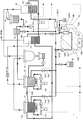
- the schematic block diagram which shows the industrial washing machine which has one Example of the oil concentration measuring apparatus which concerns on this invention as a component.
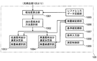
- the block diagram which shows the function of PC in the oil concentration measuring apparatus of a present Example.
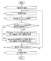
- the flowchart which shows operation
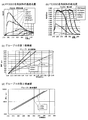
- the graph which shows the 1st calibration curve (c) and the 2nd calibration curve (d) which were created based on the spectrum of the absorbance.
- FIG. 1 shows a schematic configuration of an industrial washer 1 having an oil concentration measuring device 10 of this embodiment as a component.
- the industrial cleaning machine 1 is a device for removing oil adhering to a workpiece.
- the first cleaning tank 11, the second cleaning tank 12, the steam cleaning / drying tank 13, and the temporary It has a storage tank 14, a distillation tank 15, a heat exchanger 16, an ejector 17, a post-regeneration cleaning liquid storage tank 18, and a sample cell cleaning liquid tank 19.
- a thick solid line indicates a liquid flow path
- a thick broken line indicates a gas flow path
- a thin straight broken line indicates an electric signal path.
- the first cleaning tank 11 and the second cleaning tank 12 are provided with an ultrasonic vibrator that applies ultrasonic vibration to the cleaning liquid stored in the tank. Moreover, in order to make it easy to produce cavitation by an ultrasonic wave, the inside of the 1st washing tank 11 and the 2nd washing tank 12 is pressure-reduced with a vacuum pump, and deaeration of a washing
- the oil content of the cleaning liquid in the second cleaning tank 12 is smaller than the cleaning liquid in the first cleaning tank 11, the work is first cleaned in the first cleaning tank 11. Then, by cleaning the workpiece in the second cleaning tank 12, it is possible to minimize the oil in the cleaning liquid from reattaching to the workpiece.
- the post-regeneration cleaning liquid from which oil has been removed by the distillation tank 15 flows from the post-regeneration cleaning liquid storage tank 18 into the second cleaning tank 12 as will be described later.
- the first cleaning tank 11 and the second cleaning tank 12 are connected by a second overflow pipe 122.
- the second overflow pipe 122 has a higher connection position with the second cleaning tank 12 than a connection position with the first cleaning tank 11, and the cleaning liquid in the second cleaning tank 12 flows due to the inflow of the cleaning liquid after regeneration.
- the liquid level becomes higher than the latter connection position a part of the cleaning liquid in the second cleaning tank 12 naturally moves to the first cleaning tank 11. Therefore, as described above, the oil content of the cleaning liquid in the second cleaning tank 12 is smaller than that of the cleaning liquid in the first cleaning tank 11.
- first cleaning tank 11 and the temporary storage tank 14 are connected by a first overflow pipe 112, and the liquid level of the cleaning liquid in the first cleaning tank 11 is caused by the inflow of the cleaning liquid from the second cleaning tank 12. If it becomes higher than the connection position of the pipe
- the distillation tank 15 is provided with a float valve 151, and when the liquid in the distillation tank 15 becomes a predetermined amount or less by distillation, the cleaning liquid is introduced from the temporary storage tank 14 into the distillation tank 15.
- the distillation tank 15 is heated by a heater (not shown) and depressurized by an ejector 17. As a result, the cleaning liquid evaporates leaving the oil as a liquid, is condensed in the heat exchanger 16, is stored in the cleaning liquid storage tank 18 after regeneration, and is returned to the second cleaning tank 12 as described above.
- the steam cleaning / drying tank 13 is a tank for performing steam cleaning and drying on the workpiece cleaned in the second cleaning tank 12 as described above.
- the steam used for the steam cleaning and the cleaning liquid from which the material remaining on the surface of the workpiece has been removed are returned to the second cleaning tank 12. Further, the gas generated by the decompression of the first cleaning tank 11 and the second cleaning tank 12 and the evaporation of the cleaning liquid is recovered into the used cleaning liquid in the temporary storage tank 14.
- the sample cell cleaning liquid tank 19 is a tank in which a cleaning liquid for cleaning a sample cell 103 described later (different from a cleaning liquid that is a target of oil concentration measurement) is stored.
- the 1st washing tank 11 has the 1st circulation filtration system 111 which takes out cleaning fluid from a tank, and returns it in a tank through a filter.
- a similar second circulation filtration system 121 is also provided in the second cleaning tank 12. These circulating filtration systems remove particles having a particle size of about 10 ⁇ m or more, and cannot remove oil.
- the oil concentration measuring apparatus 10 includes a flow path 101 connected to a tank such as a first cleaning tank 11 and a second cleaning tank 12, a liquid feed pump 102 provided in the flow path 101, and a flow path. 101, a sample cell 103 provided on the downstream side of the liquid feed pump 102, a reference cell 1031 for reference measurement, a light irradiation unit 104, a light detection unit 105, and a personal computer that performs calculations and the like described later. PC) 106.
- the inflow portion 1011 of the flow path 101 is connected to the first cleaning tank 11 via the first relay pipe 113 and is connected to the second cleaning tank 12 via the second relay pipe 123.
- the first relay pipe 113 is provided with a first relay on-off valve 11V
- the second relay pipe 123 is provided with a second relay on-off valve 12V.
- the inflow portion 1011 of the flow path 101 is also connected to the distillation tank 15 and the post-regeneration cleaning liquid storage tank 18.
- the distillation tank 15 has a distillation tank on / off valve 15V and the post-regeneration cleaning liquid storage tank 18 has A post-regeneration cleaning liquid storage tank opening / closing valve 18V is provided.
- the outflow part 1012 of the flow channel 101 is connected to the temporary storage tank 14. Therefore, the cleaning liquid used for the measurement in the oil concentration measuring device 10 is distilled by the distillation tank 15 through the temporary storage tank 14, and finally returned to the second cleaning tank 12 in a state where the oil is removed. In addition, you may make it return the washing
- Both the sample cell 103 and the reference cell 1031 are quartz cells that absorb less ultraviolet light.
- the sample cell 103 is connected to the channel 101 during normal measurement, and the reference cell 1031 is connected when measuring the reference.
- the reference cell 1031 contains a cleaning liquid that does not contain oil.
- the light irradiation unit 104 irradiates the cleaning liquid (measurement target liquid) in the sample cell 103 with the ultraviolet continuous light, and enters the light source that generates the ultraviolet continuous light and the ultraviolet continuous light generated by the light source. It has an optical fiber that inputs from the end and irradiates the cleaning liquid in the sample cell 103 from the output end.
- the light detection unit 105 detects the intensity of transmitted light transmitted through the cleaning liquid in the sample cell 103 in the ultraviolet continuous light for each wavelength, and corresponds to the above-described transmitted light amount measuring unit.
- the light detection unit 105 includes a spectroscope that splits the transmitted light, an optical fiber that inputs the transmitted light from the incident end and exits from the output end to the spectroscope, and the intensity of transmitted light for each wavelength detected by the spectroscope.
- a signal conversion unit for converting the signal into a digital signal.
- the PC 106 has an absorbance calculation unit 1061, an oil concentration determination method selection unit 1062, a low concentration oil concentration determination unit 1063, a high concentration oil concentration determination unit 1064, a reference data recording unit 1065, and a calibration curve recording.
- details of the absorbance calculation unit 1061, the low concentration oil concentration determination unit 1063, the high concentration oil concentration determination unit 1064, and the oil concentration determination unit 1064 will be described later together with the operation of the oil concentration measurement device 10 of the present embodiment. To do.
- the reference data recording unit 1065 records spectrum data (reference data) of transmitted light amount measured in advance for a cleaning agent that does not contain oil.
- the calibration curve recording unit 1066 includes a first calibration curve and a second calibration curve created on the basis of data measured in advance using a sample having a known oil concentration for each group of oil components that can be used for workpiece processing. The line is housed. Examples of the first calibration curve and the second calibration curve will be described later.
- the reference value recording unit 1067 stores reference value data used in the oil concentration determination unit 1064.
- the condition input unit 1068 is used by the measurer to input measurement conditions described later using an input device such as a keyboard or a mouse.
- the measurement control unit 1069 controls the start and end of light irradiation from the light source in the light irradiation unit 104 and the start and end of the processing of each unit.
- measurement is started when the measurer inputs a predetermined measurement condition in the condition input unit 1068 and then inputs a measurement start instruction.
- the measurement condition input is information regarding the use of the processing oil for specifying the group to which the processing oil attached to the workpiece to be cleaned using the cleaning liquid to be measured belongs, for example, the material of the workpiece (A soft material such as aluminum or a hard material such as stainless steel) and a processing method (cutting or punching / pressing).
- the manufacturer and model number of the processing oil adhering to the workpiece may be input.
- a predetermined measurement start operation is performed (step S1).
- the measurement start operation includes opening the first relay opening / closing valve 11V connected to the first cleaning tank 11 selected by the condition input unit 1068. Thereby, a part of the cleaning liquid in the first cleaning tank 11 reaches the sample cell 103 through the first relay pipe 113 and the flow path 101.
- the capacity of the cleaning liquid in the first cleaning tank 11 is 120 L, whereas the flow rate of the cleaning liquid in the flow channel 101 is only about 0.1 L / min, and finally the cleaning liquid is first distilled after the distillation. Since it is returned to the washing tank 11, this measurement has no influence on the washing.
- the light irradiation unit 104 irradiates the cleaning liquid in the sample cell 103 with ultraviolet continuous light, and the light detection unit 105 detects the transmitted light that has passed through the cleaning liquid (step S2).
- the light detection unit 105 splits the transmitted light and converts the intensity of the transmitted light amount for each wavelength ⁇ , that is, the spectrum I ( ⁇ ) of the transmitted light amount into a digital signal.
- a digital signal of the spectrum I ( ⁇ ) of the transmitted light amount is input to the PC 106, and the absorbance calculation unit 1061 calculates the absorbance spectrum (step S3).
- the oil concentration determination method selection unit 1062 includes the peak wavelength (predetermined wavelength) of the transmitted light amount measured in advance using the cleaning liquid that does not contain oil, out of the absorbance A ( ⁇ ) of the obtained cleaning liquid. ) absorbance a at ⁇ p ( ⁇ p) is determined to or less than a predetermined value. If the absorbance A ( ⁇ p ) is less than or equal to a predetermined value, the process proceeds to step S51, and if greater than the predetermined value, the process proceeds to step S52.
- the oil concentration determination unit 1063 for low concentration determines the oil concentration as follows.
- the low-concentration oil concentration determination unit 1063 has a calibration curve selection unit.
- the calibration curve selection unit corresponds to an oil group that matches the conditions input from the calibration curve recording unit 1066 by the condition input unit 1068.
- the first calibration curve shows the relationship between the absorbance of the cleaning liquid containing oil and the concentration of oil at the predetermined wavelength ⁇ p .
- the oil concentration determination unit 1063 for low concentration uses the concentration value in the first calibration curve corresponding to the absorbance A ( ⁇ p ) value of the cleaning liquid that is the measurement target liquid at the predetermined wavelength ⁇ p . Determine as value.
- the oil concentration determination unit 1064 for high concentration determines the oil concentration as follows.
- the high-concentration oil concentration determination unit 1064 has a calibration curve selection unit similar to the low-concentration oil concentration determination unit 1063.
- the calibration curve selection unit is changed from the calibration curve recording unit 1066 to the condition input unit 1068.
- Data on the second calibration curve corresponding to the oil group that matches the input condition is acquired.
- the second calibration curve shows the relationship between the wavelength at which the absorbance becomes a predetermined value (predetermined absorbance) and the oil concentration.
- the predetermined absorbance is appropriately determined from the absorbance spectrum in consideration of measurement accuracy.
- the oil concentration determination unit 1064 for high concentration uses the concentration value in the second calibration curve corresponding to the wavelength value when the absorbance A ( ⁇ ) of the cleaning liquid that is the measurement target liquid becomes the predetermined absorbance. Is determined as the concentration value.
- step S6 it is confirmed in step S6 whether or not a measurement end signal instructing the end of the measurement operation is input from the condition input unit 1068. If the signal is not input, the process returns to step S2. If the signal is input, an end operation such as closing the first relay on-off valve 11V is performed (step S7), and then the measurement is ended. Thus, the measurement of the sample concentration is repeatedly performed until the measurement end signal is input.
- Only one type of first calibration curve may be prepared for one oil group, but one type may be prepared for each of a plurality of predetermined wavelengths having different values.
- the low-concentration oil concentration determination unit 1063 obtains the absorbance obtained by the measurement and the concentration value corresponding to the predetermined wavelength one by one from the first calibration curve at each of the plurality of predetermined wavelengths. Is determined as the concentration value of the liquid to be measured.
- the second calibration curve only one type may be prepared for one oil component group, but one type is prepared for each of a plurality of predetermined absorbances having different values. Also good.
- the oil concentration determination unit 1064 for high concentration uses the second calibration value for the concentration value corresponding to the value of the wavelength when the absorbance A ( ⁇ ) obtained by the measurement becomes the predetermined absorbance at each of the plurality of predetermined absorbances. Obtain one by one from the line, and determine the average value of the obtained concentration values as the concentration value of the liquid to be measured.
- the method has been described as a method for measuring the concentration of oil in the cleaning liquid in the first cleaning tank 11.
- the liquid flowing into the flow path 101 is switched by operating each valve provided in the industrial cleaning machine 1. Accordingly, the concentration of oil in the liquid stored in the second cleaning tank 12, the distillation tank 15, or the post-regeneration cleaning liquid storage tank 18 can be measured by the same method.
- the concentration of oil in the liquid stored in the second cleaning tank 12, the distillation tank 15, or the post-regeneration cleaning liquid storage tank 18 can be measured by the same method.
- the cleaning time in the first cleaning tank 11 or the second cleaning tank 12 is lengthened.
- the oil concentration in the regenerated liquid in the post-regeneration cleaning liquid storage tank 18 approaches a predetermined upper limit value, it is assumed that the ability of distillation is reduced. The remaining liquid is boiled and drained.
- the temperature during distillation is assumed to be too high, and thus the temperature is lowered.
- the concentration of oil in the residual liquid in the distillation tank 15 can be measured by the same method, and the timing of boiled / drained oil may be determined based on the concentration of oil obtained thereby.
- Example of absorbance and data of the first and second calibration curves For each of the 10 oil components shown in Table 1, a plurality of samples were prepared by mixing them with different concentrations in the same component cleaning solution. The first calibration curve and the second calibration curve were prepared after obtaining the absorbance spectrum with the oil concentration measuring apparatus of the example. These ten types of oil are classified into four groups shown in Table 1.
- the first group is a cutting oil in which the object to be processed is limited to a metal softer than iron such as aluminum
- the second group is a cutting oil in which the object to be processed may be a hard metal such as iron or stainless steel.
- Group 3 is a cutting oil used for drilling deep holes in hard metals such as stainless steel, and is also used for press and punching oils.
- Group 4 has an additive added more than Group 3 There are many press and punching oils.
- FIGS. 4 to 7 show, for each group, a spectrum of transmitted light (a) and a spectrum of absorbance (b) obtained from a sample containing one typical oil component with double circles in Table 1 for each group. Indicates.
- the spectrum of the amount of transmitted light (absorbance) was measured many times while changing the oil concentration within the range of about 100 ppm to about 50,000 ppm for each sample.
- the spectrum was shown.
- (a) and (b) in each of FIGS. 4 to 7 show only representative four types of oil samples, the spectrum of transmitted light amount is similarly applied to the other six types of oil samples.
- an absorbance spectrum Absorbance has a peak in the vicinity of a wavelength of 290 to 330 nm in any sample.
- the obtained first calibration curve of each group is shown in FIGS. 4 to 7 (c), and the second calibration curve is shown in FIGS. 4 to 7 (d).
- the calibration curve for each group shows not only the samples containing the typical oils shown in FIGS. 4 to 7 (a) and (b), but also the absorbance spectra obtained from the samples containing other oils. Created using.
- the first calibration curve was prepared by approximating the relationship between the absorbance value and the concentration at a predetermined wavelength by a function in the concentration range of 5000 ppm or less for group 1, 2600 ppm or less for groups 2 and 4, and 3500 ppm or less for group 3.
- the first calibration curve was prepared for two predetermined wavelengths for each group, with wavelengths of 290 nm and 295 nm for groups 1 to 3 and wavelengths of 330 nm and 335 nm for group 4.
- the reason why the absorbance values at wavelengths 290 nm and 295 nm are not used only for group 4 is that the absorbance is high when the concentration is about 2000 ppm, and the amount of transmitted light is very low, so it is determined that the error is large.
- the function to be approximated is a linear function in principle, but in Group 1, since the error is large, it is a quadratic function.
- the second calibration curve was created by approximating the relationship between wavelength and concentration at a predetermined absorbance determined for each of groups 1 to 4 with a function.
- the predetermined absorbance is determined so as to include the absorbance of a sample having a concentration of about 10,000 ppm or more, and to include the absorbance of a sample having a concentration of about 2000 ppm as much as possible.
- the function to be approximated was an exponential function.
- the first calibration curve and the second calibration curve can be determined using a sample with a known concentration, and a measurement with respect to a sample with an unknown concentration can be performed using these calibration curves.
- the predetermined value of the absorbance A ( ⁇ p ) used in step S4 is 4000 ppm for group 1, 2000 ppm for groups 2 and 4, and 3000 ppm for group 3.
- the experimental results are shown in the graph of FIG.
- the calculated value is plotted on the horizontal axis and the experimental value is plotted on the vertical axis.
- a data point falls between two dashed lines in the graph if the experimental value falls within ⁇ 20% of the calculated value.
- data for all samples are shown in one graph. As shown in this graph, it can be said that most of the experimental data is within ⁇ 20% of the calculated value.
- An accuracy of about ⁇ 20% is sufficient for use in setting cleaning conditions for industrial cleaning machines and conditions for distillation of cleaning liquids.
- first relay pipe 11V ... first relay on-off valve 12 ... second cleaning tank 121 ... first 2-circulation filtration system 122 ... second overflow pipe 123 ... second relay pipe 12V ... second relay on-off valve 13 ... steam cleaning / drying tank 14 ... temporary storage tank 15 ... distillation tank 15V ... distillation tank on-off valve 16 ... heat exchanger 17 ... Ejector 18 ... Post-regeneration cleaning liquid reservoir 18V ... Post-regeneration cleaning liquid storage tank on-off valve 19 ... Sample cell cleaning liquid tank
Landscapes
- Physics & Mathematics (AREA)
- Chemical & Material Sciences (AREA)
- Health & Medical Sciences (AREA)
- Life Sciences & Earth Sciences (AREA)
- Engineering & Computer Science (AREA)
- Pathology (AREA)
- Biochemistry (AREA)
- General Health & Medical Sciences (AREA)
- General Physics & Mathematics (AREA)
- Immunology (AREA)
- Analytical Chemistry (AREA)
- Spectroscopy & Molecular Physics (AREA)
- Chemical Kinetics & Catalysis (AREA)
- General Chemical & Material Sciences (AREA)
- Oil, Petroleum & Natural Gas (AREA)
- Food Science & Technology (AREA)
- Medicinal Chemistry (AREA)
- Mathematical Physics (AREA)
- Theoretical Computer Science (AREA)
- Investigating Or Analysing Materials By Optical Means (AREA)
Abstract
Description
a) 前記測定対象液につき光の吸収が観測される270~400nmの間の所定波長帯内の吸光度のスペクトルを測定する吸光度測定手段と、
b) 前記所定波長帯内の所定波長における吸光度と、前記成分の濃度と該所定波長における吸光度の関係を示す第1検量線とに基づいて前記油分の濃度値を求める低濃度用油分濃度決定手段と、
c) 前記所定波長帯のうち、前記吸光度のスペクトルにおいて吸光度が所定吸光度となる波長と、前記成分の濃度と該所定吸光度となる波長の関係を示す第2検量線とに基づいて、前記油分の濃度値を求める高濃度用油分濃度決定手段と、
d) 所定基準に基づいて、前記低濃度用油分濃度決定手段と前記高濃度用油分濃度決定手段から前記油分の濃度値を求める手段を選択する油分濃度決定方法選択手段と
を備えることを特徴とする。
前記油分の用途に応じた複数の第1検量線及び第2検量線を記憶する記憶手段と、
使用者が前記用途を入力する入力手段と、
前記入力手段により入力された用途に基づいて、前記記憶手段に記憶された第1検量線及び第2検量線から、前記低濃度用油分濃度決定手段において使用する第1検量線及び前記高濃度用油分濃度決定手段において使用する第2検量線を選択する検量線選択手段と
を備えることができる。このようにグループ分けされた検量線を用いることにより、用意すべき第1検量線及び第2検量線の種類を少なくすることができると共に、使用者が測定対象液に混入した油分のメーカや型番を調べる必要がなくなる。
前記測定対象液が流れる流路を更に備え、
前記光照射手段が該流路内の測定対象液に前記連続光を照射し、前記透過光量測定手段が該流路内の測定対象液を透過した光の光量を測定する
という構成を取ることができる。これにより、流路を通過する測定対象液の油分の濃度を常時計測することができる。あるいは、この構成において更に、前記流路に流入する測定対象液を切り替える測定対象液切替手段を備えることもできる。この場合には、例えば、炭化水素系洗浄液を用いた工業用洗浄機において液体洗浄槽内の洗浄液と蒸留槽内の残液の間で測定対象液を切り替えることで、両者の油分濃度を計測することができる。
前記測定対象液につき光の吸収が観測される270~400nmの間の所定波長帯内の吸光度のスペクトルを測定し、
所定基準を満たす場合には、前記所定波長帯内の所定波長における吸光度と、前記成分の濃度と該所定波長における吸光度の関係を示す第1検量線とに基づいて前記油分の濃度値を求め、
前記所定基準を満たさない場合には、前記所定波長帯のうち、前記吸光度のスペクトルにおいて吸光度が所定吸光度となる波長と、前記成分の濃度と該所定吸光度における波長の関係を示す第2検量線とに基づいて、前記油分の濃度値を求める
ことを特徴とする。
本実施例の油分濃度計測装置10について説明する前に、まず、工業用洗浄機1の全体構成及びワークの洗浄の動作を説明する。第1洗浄槽11及び第2洗浄槽12には、槽内に貯留される洗浄液に超音波振動を付与する超音波振動子が設けられている。また、超音波によるキャビテーションを生じ易くするために、第1洗浄槽11及び第2洗浄槽12内は真空ポンプにより減圧され、洗浄液の脱気が行われる。これら第1洗浄槽11及び第2洗浄槽12に洗浄液を貯留したうえで、ワークを洗浄液に浸漬し、超音波振動を付与することにより、ワークが洗浄される。ここで、後述の理由により、第1洗浄槽11内の洗浄液よりも第2洗浄槽12内の洗浄液の方が油分の含有量が少なくなることから、まず第1洗浄槽11でワークを洗浄し、次にそのワークを第2洗浄槽12で洗浄することにより、洗浄液中の油分がワークに再付着することを最小限に抑えることができる。
次に、工業用洗浄機1中の油分濃度計測装置10の構成について詳細に説明する。油分濃度計測装置10は、後述のように第1洗浄槽11や第2洗浄槽12等の槽と接続される流路101と、流路101中に設けられた送液ポンプ102と、流路101中の送液ポンプ102よりも下流側に設けられた試料セル103と、リファレンス測定用のリファレンスセル1031と、光照射部104と、光検出部105と、後述の計算等を行うパーソナルコンピュータ(PC)106を有する。
図3のフローチャートを用いて、本実施例の油分濃度計測装置10の動作を説明する。以下では一例として、第1洗浄槽11に貯留されている洗浄液を測定する場合について説明するが、第2洗浄槽12、蒸留槽15、再生後洗浄液貯留槽18に貯留されている液を測定する場合も同様である。
A(λ)=log10(I0(λ)/I(λ))
により求める。
表1に示した10種類の油分についてそれぞれ、同じ成分の洗浄液に異なる濃度で混合した複数の試料を作製し、本実施例の油分濃度計測装置により吸光度のスペクトルを取得したうえで第1検量線及び第2検量線を作成した。これら10種類の油分は表1に示す4つのグループに分類される。第1グループは、加工対象物がアルミニウム等の鉄よりも軟らかい金属に限定される切削油、第2グループは、加工対象物が鉄やステンレス鋼等の硬い金属であってもよい切削油、第3グループは、ステンレス鋼等の硬い金属に深い穴を空ける際に用いる切削油であると共に、プレス・打抜き油にも使用されるもの、第4グループは、第3グループよりも添加剤の添加量が多いプレス・打抜き油である。

101…流路
1011…流路の流入部
1012…流路の流出部
102…送液ポンプ
103…試料セル
1031…リファレンスセル
104…光照射部
105…光検出部
106…PC
1061…吸光度算出部
1062…油分濃度決定方法選択部
1063…低濃度用油分濃度決定部
1064…高濃度用油分濃度決定部
1065…リファレンスデータ記録部
1066…検量線記録部
1067…基準値記録部
1068…条件入力部
1069…測定制御部
11…第1洗浄槽
111…第1循環濾過系
112…第1オーバーフロー管
113…第1中継管
11V…第1中継開閉弁
12…第2洗浄槽
121…第2循環濾過系
122…第2オーバーフロー管
123…第2中継管
12V…第2中継開閉弁
13…蒸気洗浄・乾燥槽
14…一時貯留槽
15…蒸留槽
15V…蒸留槽開閉弁
16…熱交換器
17…エゼクタ
18…再生後洗浄液貯留槽
18V…再生後洗浄液貯留槽開閉弁
19…試料セル洗浄液槽
Claims (10)
- 炭素原子の多価結合を有しない分子が主成分であって、炭素原子の多価結合を有する分子を含有する油分が混入した測定対象液における該油分の濃度を計測する装置であって、
a) 前記測定対象液につき光の吸収が観測される270~400nmの間の所定波長帯内の吸光度のスペクトルを測定する吸光度測定手段と、
b) 前記所定波長帯内の所定波長における吸光度と、前記成分の濃度と該所定波長における吸光度の関係を示す第1検量線とに基づいて前記油分の濃度値を求める低濃度用油分濃度決定手段と、
c) 前記所定波長帯のうち、前記吸光度のスペクトルにおいて吸光度が所定吸光度となる波長と、前記成分の濃度と該所定吸光度となる波長の関係を示す第2検量線とに基づいて、前記油分の濃度値を求める高濃度用油分濃度決定手段と、
d) 所定基準に基づいて、前記低濃度用油分濃度決定手段と前記高濃度用油分濃度決定手段から前記油分の濃度値を求める手段を選択する油分濃度決定方法選択手段と
を備えることを特徴とする油分濃度計測装置。 - 前記所定基準が、前記所定波長における吸光度であることを特徴とする請求項1に記載の油分濃度計測装置。
- 前記所定波長が前記所定波長帯内の複数の波長であり、
前記低濃度用油分濃度決定手段が、複数の所定波長の各々について、前記吸光度測定手段により測定された該所定波長における吸光度と該所定波長において作成された前記油分の濃度と吸光度の関係を示す第1検量線とに基づいて前記油分の仮濃度値を求め、得られた複数の仮濃度値に基づいて前記油分の濃度値を求める
ことを特徴とする請求項1又は2に記載の油分濃度計測装置。 - 前記所定吸光度が複数の吸光度であり、
前記高濃度用油分濃度決定手段が、複数の所定吸光度の各々について、前記吸光度測定手段により測定された該所定吸光度における波長と該所定吸光度において作成された前記油分の濃度と該所定吸光度となる波長の関係を示す第2検量線とに基づいて前記油分の仮濃度値を求め、得られた複数の仮濃度値に基づいて前記油分の濃度値を求める
ことを特徴とする請求項1~3のいずれかに記載の油分濃度計測装置。 - 前記所定波長が、前記成分を含有しない標準試料により得られる透過光量の強度が最大となる波長であることを特徴とする請求項1~4のいずれかに記載の油分濃度計測装置。
- 前記油分の用途に応じた複数の第1検量線及び第2検量線を記憶する記憶手段と、
前記用途を入力する入力手段と、
前記入力手段により入力された用途に基づいて、前記記憶手段に記憶された第1検量線及び第2検量線から、前記低濃度用油分濃度決定手段において使用する第1検量線及び前記高濃度用油分濃度決定手段において使用する第2検量線を選択する検量線選択手段と
を備えることを特徴とする請求項1~5のいずれかに記載の油分濃度計測装置。 - 前記測定対象液が流れる流路を更に備え、
前記光照射手段が該流路内の測定対象液に前記連続光を照射し、前記透過光量測定手段が該流路内の測定対象液を透過した光の光量を測定する
ことを備えることを特徴とする請求項1~6のいずれかに記載の油分濃度計測装置。 - 前記流路に流入する測定対象液を切り替える測定対象液切替手段を備えることを特徴とする請求項7に記載の油分濃度計測装置。
- 炭素原子の多価結合を有しない分子が主成分であって、炭素原子の多価結合を有する分子を含有する油分が混入した測定対象液における該油分の濃度を計測する方法であって、
前記測定対象液につき光の吸収が観測される270~400nmの間の所定波長帯内の吸光度のスペクトルを測定し、
所定基準を満たす場合には、前記所定波長帯内の所定波長における吸光度と、前記成分の濃度と該所定波長における吸光度の関係を示す第1検量線とに基づいて前記油分の濃度値を求め、
前記所定基準を満たさない場合には、前記所定波長帯のうち、前記吸光度のスペクトルにおいて吸光度が所定吸光度となる波長と、前記成分の濃度と該所定吸光度における波長の関係を示す第2検量線とに基づいて、前記油分の濃度値を求める
ことを特徴とする油分濃度計測方法。 - 炭素原子の多価結合を有しない分子が主成分であって、炭素原子の多価結合を有する分子を含有する油分が混入した測定対象液における該油分の濃度を計測する方法であって、
前記測定対象液につき光の吸収が観測される270~400nmの間の所定波長帯内の所定波長における吸光度を測定し、
前記吸光度が所定基準を満たす場合には、該吸光度と、前記成分の濃度と該所定波長における吸光度の関係を示す第1検量線とに基づいて前記油分の濃度値を求め、
前記所定基準を満たさない場合には、前記測定対象液につき前記所定波長帯内の吸光度のスペクトルを測定したうえで、該スペクトルにおいて吸光度が所定吸光度となる波長と、前記成分の濃度と該所定吸光度における波長の関係を示す第2検量線とに基づいて、前記油分の濃度値を求める
ことを特徴とする油分濃度計測方法。
Priority Applications (4)
| Application Number | Priority Date | Filing Date | Title |
|---|---|---|---|
| JP2016530031A JP5981083B1 (ja) | 2015-02-17 | 2016-01-19 | 油分濃度計測装置及び油分濃度計測方法 |
| US15/314,813 US9739707B2 (en) | 2015-02-17 | 2016-01-19 | Oil concentration measurement system and oil concentration measurement method |
| EP16752184.8A EP3139151B1 (en) | 2015-02-17 | 2016-01-19 | Oil concentration measurement device and oil concentration measurement method |
| CN201680001539.6A CN106461541B (zh) | 2015-02-17 | 2016-01-19 | 油分浓度测量装置和油分浓度测量方法 |
Applications Claiming Priority (2)
| Application Number | Priority Date | Filing Date | Title |
|---|---|---|---|
| JP2015028202 | 2015-02-17 | ||
| JP2015-028202 | 2015-02-17 |
Publications (1)
| Publication Number | Publication Date |
|---|---|
| WO2016132795A1 true WO2016132795A1 (ja) | 2016-08-25 |
Family
ID=56688936
Family Applications (1)
| Application Number | Title | Priority Date | Filing Date |
|---|---|---|---|
| PCT/JP2016/051369 Ceased WO2016132795A1 (ja) | 2015-02-17 | 2016-01-19 | 油分濃度計測装置及び油分濃度計測方法 |
Country Status (5)
| Country | Link |
|---|---|
| US (1) | US9739707B2 (ja) |
| EP (1) | EP3139151B1 (ja) |
| JP (1) | JP5981083B1 (ja) |
| CN (1) | CN106461541B (ja) |
| WO (1) | WO2016132795A1 (ja) |
Cited By (3)
| Publication number | Priority date | Publication date | Assignee | Title |
|---|---|---|---|---|
| WO2018025813A1 (ja) * | 2016-08-04 | 2018-02-08 | アクトファイブ株式会社 | 油分濃度計測装置及び油分濃度計測方法 |
| JPWO2019043858A1 (ja) * | 2017-08-31 | 2020-04-16 | 株式会社島津製作所 | 原子吸光分光光度計及び原子吸光測定方法 |
| CN111208079A (zh) * | 2018-11-22 | 2020-05-29 | 天津工业大学 | 一种基于紫外可见光谱的四元掺伪葡萄籽油的定量检测方法 |
Families Citing this family (6)
| Publication number | Priority date | Publication date | Assignee | Title |
|---|---|---|---|---|
| CN108469472A (zh) * | 2017-12-19 | 2018-08-31 | 江苏康达检测技术股份有限公司 | 固体废弃物中甲醛浓度的测定方法 |
| EP3783275A1 (en) * | 2019-08-21 | 2021-02-24 | Grundfos Holding A/S | Pump system |
| CN111735788B (zh) * | 2020-07-21 | 2021-01-05 | 赛默飞世尔(上海)仪器有限公司 | 在水质分析仪中用于确定样品浓度的方法和水质分析仪 |
| FR3132770B1 (fr) * | 2022-02-11 | 2024-02-02 | Ifp Energies Now | Procédé pour le suivi dans le temps de la concentration en un composé chimique d’un fluide, au moyen d’un système de mesure optique |
| CN116341764B (zh) * | 2023-05-24 | 2023-09-26 | 中国石油大学(华东) | 基于历史数据的成品油管道混油浓度分布预测方法及系统 |
| FR3151399B1 (fr) * | 2023-07-18 | 2025-07-11 | Ifp Energies Now | Procédé pour le suivi dans le temps de la concentration en un composé chimique d’un fluide, au moyen d’un système de mesure optique et d’un capteur de température |
Citations (6)
| Publication number | Priority date | Publication date | Assignee | Title |
|---|---|---|---|---|
| JPS56147042A (en) * | 1980-04-17 | 1981-11-14 | Olympus Optical Co Ltd | Method for conversion of concentration |
| JPH07294519A (ja) * | 1994-03-04 | 1995-11-10 | Kyoto Daiichi Kagaku:Kk | 尿中成分の測定方法 |
| JPH0961349A (ja) * | 1995-08-28 | 1997-03-07 | Tosoh Corp | 洗浄剤中の汚れ量測定方法及び装置 |
| JPH09292328A (ja) * | 1996-04-25 | 1997-11-11 | Corona Denki Kk | 濁度計 |
| US7616316B1 (en) * | 2006-02-27 | 2009-11-10 | Southwest Sciences Incorporated | Gas measurement over extreme dynamic range of concentrations |
| JP2011220941A (ja) * | 2010-04-13 | 2011-11-04 | Tokuyama Corp | フッ化カルシウム単結晶の評価方法、及び光学部材用の硝材の製造方法 |
Family Cites Families (9)
| Publication number | Priority date | Publication date | Assignee | Title |
|---|---|---|---|---|
| US5411558A (en) * | 1992-09-08 | 1995-05-02 | Kao Corporation | Heavy oil emulsion fuel and process for production thereof |
| CN1087429C (zh) | 1994-03-04 | 2002-07-10 | 株式会社京都第一科学 | 同时定量分析数种尿中成分的测定方法及测定装置 |
| FR2845013B1 (fr) | 2002-09-30 | 2004-12-24 | Totalfinaelf France | Procede et dispositif pour la conduite en continu d'un processus de preparation d'un carburant, notamment pour moteur diesel, par melange en ligne de ses constituants |
| US8023690B2 (en) * | 2005-02-04 | 2011-09-20 | Baker Hughes Incorporated | Apparatus and method for imaging fluids downhole |
| JPWO2008133281A1 (ja) * | 2007-04-24 | 2010-07-29 | キヤノンセミコンダクターエクィップメント株式会社 | 流動状態における屈折率分布を用いた濃度測定法及びそのシステム |
| US8899107B2 (en) * | 2009-03-11 | 2014-12-02 | Schlumberger Technology Corporation | Downhole determination of asphaltene content |
| CN101943662A (zh) * | 2010-09-16 | 2011-01-12 | 爱阔特(上海)清洗设备制造有限公司 | 清洗液油分浓度测定方法及装置 |
| FR2970082B1 (fr) * | 2011-01-05 | 2013-01-11 | Total Sa | Methode de dosage des huiles lourdes |
| CA2867779C (en) | 2012-03-19 | 2021-06-15 | Banu ORMECI BECKERS | Measurement of treatment agent in a process stream using ultraviolet-visible (uv-vis) spectroscopy, and related systems and processes |
-
2016
- 2016-01-19 WO PCT/JP2016/051369 patent/WO2016132795A1/ja not_active Ceased
- 2016-01-19 US US15/314,813 patent/US9739707B2/en active Active
- 2016-01-19 CN CN201680001539.6A patent/CN106461541B/zh active Active
- 2016-01-19 JP JP2016530031A patent/JP5981083B1/ja active Active
- 2016-01-19 EP EP16752184.8A patent/EP3139151B1/en active Active
Patent Citations (6)
| Publication number | Priority date | Publication date | Assignee | Title |
|---|---|---|---|---|
| JPS56147042A (en) * | 1980-04-17 | 1981-11-14 | Olympus Optical Co Ltd | Method for conversion of concentration |
| JPH07294519A (ja) * | 1994-03-04 | 1995-11-10 | Kyoto Daiichi Kagaku:Kk | 尿中成分の測定方法 |
| JPH0961349A (ja) * | 1995-08-28 | 1997-03-07 | Tosoh Corp | 洗浄剤中の汚れ量測定方法及び装置 |
| JPH09292328A (ja) * | 1996-04-25 | 1997-11-11 | Corona Denki Kk | 濁度計 |
| US7616316B1 (en) * | 2006-02-27 | 2009-11-10 | Southwest Sciences Incorporated | Gas measurement over extreme dynamic range of concentrations |
| JP2011220941A (ja) * | 2010-04-13 | 2011-11-04 | Tokuyama Corp | フッ化カルシウム単結晶の評価方法、及び光学部材用の硝材の製造方法 |
Non-Patent Citations (1)
| Title |
|---|
| See also references of EP3139151A4 * |
Cited By (3)
| Publication number | Priority date | Publication date | Assignee | Title |
|---|---|---|---|---|
| WO2018025813A1 (ja) * | 2016-08-04 | 2018-02-08 | アクトファイブ株式会社 | 油分濃度計測装置及び油分濃度計測方法 |
| JPWO2019043858A1 (ja) * | 2017-08-31 | 2020-04-16 | 株式会社島津製作所 | 原子吸光分光光度計及び原子吸光測定方法 |
| CN111208079A (zh) * | 2018-11-22 | 2020-05-29 | 天津工业大学 | 一种基于紫外可见光谱的四元掺伪葡萄籽油的定量检测方法 |
Also Published As
| Publication number | Publication date |
|---|---|
| CN106461541A (zh) | 2017-02-22 |
| JPWO2016132795A1 (ja) | 2017-04-27 |
| US20170199118A1 (en) | 2017-07-13 |
| EP3139151A1 (en) | 2017-03-08 |
| EP3139151B1 (en) | 2020-05-27 |
| US9739707B2 (en) | 2017-08-22 |
| EP3139151A4 (en) | 2017-06-21 |
| JP5981083B1 (ja) | 2016-08-31 |
| CN106461541B (zh) | 2018-04-10 |
Similar Documents
| Publication | Publication Date | Title |
|---|---|---|
| JP5981083B1 (ja) | 油分濃度計測装置及び油分濃度計測方法 | |
| CN102224288B (zh) | 浑浊度传感器 | |
| JP6468916B2 (ja) | 基板処理装置および基板処理方法 | |
| WO2018061445A1 (ja) | 基板処理装置 | |
| KR102511986B1 (ko) | 기판 처리 장치 및 기판 처리 방법 | |
| JP5470409B2 (ja) | 洗浄装置、洗浄設備および洗浄方法 | |
| Ying et al. | High efficiency regeneration performance of exhausted activated carbon by superheated steam and comparison with conventional chemical regeneration method | |
| US8863763B1 (en) | Sonication cleaning with a particle counter | |
| JP7153923B2 (ja) | 油分濃度計測装置及び油分濃度計測方法 | |
| KR101165190B1 (ko) | 저농도 총인 자동 측정 장치 | |
| JP5267429B2 (ja) | 赤外線吸収分析方法 | |
| JP2019192864A (ja) | 基板処理装置および基板処理方法 | |
| JP5813417B2 (ja) | 酸洗液の管理方法及び装置 | |
| JP6306546B2 (ja) | 真空蒸留装置 | |
| KR100441249B1 (ko) | 반도체 제조 공정에서의 티오씨 측정 장치 및 그 측정 방법 | |
| JP6390351B2 (ja) | 分析装置 | |
| JPH0961349A (ja) | 洗浄剤中の汚れ量測定方法及び装置 | |
| CN104511451B (zh) | 一种核主泵制造过程中所用耗材的清洁度的控制方法及其检测方法 | |
| CN106150490A (zh) | 钻井实时监测用自动捞砂和光谱测定仪 | |
| KR101641736B1 (ko) | 혼산농도 자동측정장치 및 그 방법 | |
| Silva et al. | Underwater determination of calcium and strontium ions in oilfield produced water by laser-induced breakdown spectroscopy (LIBS) | |
| Himma et al. | In-situ monitoring and understanding of wetting in membrane distillation by means of optical coherence tomography | |
| Shi et al. | Optimizing oily wastewater treatment via wet peroxide oxidation using response surface methodology | |
| JP2024017876A (ja) | 超純水製造装置の運転管理方法および運転管理システム | |
| JP2006194874A (ja) | ケミカル溶液の汚染分析方法及びその汚染分析システム |
Legal Events
| Date | Code | Title | Description |
|---|---|---|---|
| ENP | Entry into the national phase |
Ref document number: 2016530031 Country of ref document: JP Kind code of ref document: A |
|
| 121 | Ep: the epo has been informed by wipo that ep was designated in this application |
Ref document number: 16752184 Country of ref document: EP Kind code of ref document: A1 |
|
| REEP | Request for entry into the european phase |
Ref document number: 2016752184 Country of ref document: EP |
|
| WWE | Wipo information: entry into national phase |
Ref document number: 15314813 Country of ref document: US Ref document number: 2016752184 Country of ref document: EP |
|
| NENP | Non-entry into the national phase |
Ref country code: DE |