WO2016132811A1 - ニッケル合金多孔体の製造方法 - Google Patents
ニッケル合金多孔体の製造方法 Download PDFInfo
- Publication number
- WO2016132811A1 WO2016132811A1 PCT/JP2016/051784 JP2016051784W WO2016132811A1 WO 2016132811 A1 WO2016132811 A1 WO 2016132811A1 JP 2016051784 W JP2016051784 W JP 2016051784W WO 2016132811 A1 WO2016132811 A1 WO 2016132811A1
- Authority
- WO
- WIPO (PCT)
- Prior art keywords
- nickel
- nickel alloy
- metal
- porous body
- powder
- Prior art date
- Legal status (The legal status is an assumption and is not a legal conclusion. Google has not performed a legal analysis and makes no representation as to the accuracy of the status listed.)
- Ceased
Links
Images






Classifications
-
- C—CHEMISTRY; METALLURGY
- C25—ELECTROLYTIC OR ELECTROPHORETIC PROCESSES; APPARATUS THEREFOR
- C25D—PROCESSES FOR THE ELECTROLYTIC OR ELECTROPHORETIC PRODUCTION OF COATINGS; ELECTROFORMING; APPARATUS THEREFOR
- C25D1/00—Electroforming
- C25D1/08—Perforated or foraminous objects, e.g. sieves
-
- B—PERFORMING OPERATIONS; TRANSPORTING
- B22—CASTING; POWDER METALLURGY
- B22F—WORKING METALLIC POWDER; MANUFACTURE OF ARTICLES FROM METALLIC POWDER; MAKING METALLIC POWDER; APPARATUS OR DEVICES SPECIALLY ADAPTED FOR METALLIC POWDER
- B22F1/00—Metallic powder; Treatment of metallic powder, e.g. to facilitate working or to improve properties
- B22F1/12—Metallic powder containing non-metallic particles
-
- C—CHEMISTRY; METALLURGY
- C22—METALLURGY; FERROUS OR NON-FERROUS ALLOYS; TREATMENT OF ALLOYS OR NON-FERROUS METALS
- C22C—ALLOYS
- C22C1/00—Making non-ferrous alloys
- C22C1/08—Alloys with open or closed pores
-
- C—CHEMISTRY; METALLURGY
- C23—COATING METALLIC MATERIAL; COATING MATERIAL WITH METALLIC MATERIAL; CHEMICAL SURFACE TREATMENT; DIFFUSION TREATMENT OF METALLIC MATERIAL; COATING BY VACUUM EVAPORATION, BY SPUTTERING, BY ION IMPLANTATION OR BY CHEMICAL VAPOUR DEPOSITION, IN GENERAL; INHIBITING CORROSION OF METALLIC MATERIAL OR INCRUSTATION IN GENERAL
- C23C—COATING METALLIC MATERIAL; COATING MATERIAL WITH METALLIC MATERIAL; SURFACE TREATMENT OF METALLIC MATERIAL BY DIFFUSION INTO THE SURFACE, BY CHEMICAL CONVERSION OR SUBSTITUTION; COATING BY VACUUM EVAPORATION, BY SPUTTERING, BY ION IMPLANTATION OR BY CHEMICAL VAPOUR DEPOSITION, IN GENERAL
- C23C10/00—Solid state diffusion of only metal elements or silicon into metallic material surfaces
- C23C10/28—Solid state diffusion of only metal elements or silicon into metallic material surfaces using solids, e.g. powders, pastes
-
- C—CHEMISTRY; METALLURGY
- C25—ELECTROLYTIC OR ELECTROPHORETIC PROCESSES; APPARATUS THEREFOR
- C25D—PROCESSES FOR THE ELECTROLYTIC OR ELECTROPHORETIC PRODUCTION OF COATINGS; ELECTROFORMING; APPARATUS THEREFOR
- C25D5/00—Electroplating characterised by the process; Pretreatment or after-treatment of workpieces
- C25D5/48—After-treatment of electroplated surfaces
- C25D5/50—After-treatment of electroplated surfaces by heat-treatment
-
- C—CHEMISTRY; METALLURGY
- C25—ELECTROLYTIC OR ELECTROPHORETIC PROCESSES; APPARATUS THEREFOR
- C25D—PROCESSES FOR THE ELECTROLYTIC OR ELECTROPHORETIC PRODUCTION OF COATINGS; ELECTROFORMING; APPARATUS THEREFOR
- C25D5/00—Electroplating characterised by the process; Pretreatment or after-treatment of workpieces
- C25D5/54—Electroplating of non-metallic surfaces
- C25D5/56—Electroplating of non-metallic surfaces of plastics
-
- B—PERFORMING OPERATIONS; TRANSPORTING
- B22—CASTING; POWDER METALLURGY
- B22F—WORKING METALLIC POWDER; MANUFACTURE OF ARTICLES FROM METALLIC POWDER; MAKING METALLIC POWDER; APPARATUS OR DEVICES SPECIALLY ADAPTED FOR METALLIC POWDER
- B22F2301/00—Metallic composition of the powder or its coating
- B22F2301/15—Nickel or cobalt
-
- B—PERFORMING OPERATIONS; TRANSPORTING
- B22—CASTING; POWDER METALLURGY
- B22F—WORKING METALLIC POWDER; MANUFACTURE OF ARTICLES FROM METALLIC POWDER; MAKING METALLIC POWDER; APPARATUS OR DEVICES SPECIALLY ADAPTED FOR METALLIC POWDER
- B22F2304/00—Physical aspects of the powder
- B22F2304/10—Micron size particles, i.e. above 1 micrometer up to 500 micrometer
Definitions
- the present invention relates to a method for producing a nickel alloy porous body that can be used as a current collector for a battery, a filter, a catalyst carrier, etc., has excellent strength and toughness, is low in cost, and corresponds to a wide range of materials.
- Patent Document 1 Japanese Patent Application Laid-Open No. 07-150270 (Patent Document 1), reinforcing fine particles such as oxides, carbides and nitrides of elements belonging to groups II to VI of the periodic table are formed on the skeleton surface of a three-dimensional network resin having communication holes. Obtained by applying a paint containing Ni, and providing a Ni alloy or Cu alloy metal plating layer on the paint film, followed by heat treatment to disperse the fine particles in the metal plating layer. Strong metal porous bodies have been proposed.
- the porous metal body since the reinforcing fine particles are dispersed in the metal plating layer which is the base layer, the porous metal body has a high breaking strength but a small breaking elongation, and is suitable for processing involving plastic deformation such as bending and crushing. Is weak and has the problem of breaking.
- Patent Document 2 Japanese Patent Publication No. 38-17554
- Patent Document 3 Japanese Patent Application Laid-Open No. 09-017432
- Patent Document 4 Japanese Patent Application Laid-Open No. 2001-226723
- a slurry of metal or metal oxide powder and resin is disclosed.
- a porous metal body obtained by applying or spraying to a three-dimensional network resin and performing a drying treatment after drying.
- the porous metal body produced by the sintering method forms a skeleton by sintering metal or metal oxide powders, even if the particle size of the powder is reduced, not a few pores are generated in the skeleton cross section. Resulting in.
- Patent Document 5 Japanese Patent Laid-Open No. 08-0112929 (Patent Document 5) and Japanese Patent Laid-Open No. 08-232033 (Patent Document 6), a Ni porous film formed by a plating method using a three-dimensional network resin imparted with conductivity as a support.
- a porous metal body obtained by a diffusion permeation method in which a body is embedded in Cr or Al and NH 4 Cl powder and subjected to heat treatment in an Ar or H 2 gas atmosphere has been proposed.
- the diffusion permeation method is expensive because of low productivity, and there is a problem that the elements that can be alloyed with the Ni porous body are limited to Cr and Al.
- Patent Document 7 when the surface of a resin molded body having a three-dimensional network structure is subjected to a conductive treatment, a metal powder is mixed and applied to the carbon paint, and then the desired shape is applied. There has been proposed a method of obtaining a homogeneous alloy porous body by electroplating a metal and heat-treating it.
- Patent Document 7 a porous metal body suitable for battery current collectors, filters, catalyst carriers, etc., excellent in strength and toughness, low in cost, and compatible with a wide range of materials is manufactured. Can do.
- the method described in Patent Document 7 makes it easy to control the concentration when the content of the metal to be added is small (for example, about 5% by mass or less). It was found that there was room for improvement. As a result of further investigation about this cause, when the resin molded body is burned and removed, the phenomenon that the metal particles remain attached to the surface of the resin molded body and cannot be taken into the metal plating layer is partially seen. I found it to be the cause.
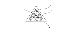
- FIGS. 3A to 3C are conceptual diagrams showing the state of the cross section of the resin molded body skeleton in each step when a porous metal body is produced by the method described in Patent Document 7.
- FIG. 1 in order to make the surface of the resin molded body 1 conductive, a carbon paint containing the metal powder 2 is applied to the surface of the resin molded body 1 (see FIG. 3A). Thereby, the surface of the resin molding 1 becomes conductive. Subsequently, a desired metal is coated by electrolytic plating. Thereby, as shown in FIG. 3B, the metal plating layer 3 is formed on the surface of the resin molded body 1.
- the present invention provides a method for producing a nickel alloy porous body that can easily control the concentration and can uniformly diffuse the added metal into the porous body even when the concentration of the metal added to nickel is low.
- the purpose is to provide.
- the method for producing a nickel alloy porous body includes: (1) applying a paint containing nickel alloy powder of nickel and an additive metal to the surface of the skeleton of a resin molded body having a three-dimensional network structure; A step of plating nickel on the surface of the skeleton of the resin molded body to which the paint is applied; Removing the resin molded body; Diffusing the additive metal into the nickel by heat treatment; The manufacturing method of the nickel alloy porous body which has this.
- a paint containing nickel alloy powder of nickel and an additive metal is applied to the surface of a skeleton of a resin molded body having a three-dimensional network structure. And a process of A step of plating nickel on the surface of the skeleton of the resin molded body to which the paint is applied; Removing the resin molded body; Diffusing the additive metal into the nickel by heat treatment; The manufacturing method of the nickel alloy porous body which has this. According to the invention described in (1) above, even when the concentration of the metal added to nickel is low, the concentration can be easily controlled and the added metal can be uniformly diffused into the porous body. A method for producing a nickel alloy porous body can be provided.
- the additive metal is selected from the group consisting of Cr, Sn, Co, Cu, Al, Ti, Mn, Fe, Mo, and W. Any one or more metals are preferable. According to the invention described in (2) above, any one or more additive metals selected from the group consisting of Al, Ti, Cr, Mn, Fe, Co, Cu, Mo, Sn, and W in the nickel porous body Can be uniformly distributed, and the concentration can be easily controlled.
- the particle diameter of the nickel alloy powder can be reduced to facilitate the diffusion of the additive metal into the nickel layer.
- the paint containing the nickel alloy powder preferably further contains carbon powder. According to the invention as described in said (4), the electroconductivity of the surface of a resin molding can be improved more and nickel plating can be performed easily.
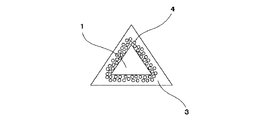
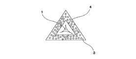
- FIGS. 1A to 1C are conceptual diagrams showing the state of the cross section of a resin molded body skeleton in each step when a nickel alloy porous body is manufactured by a method for manufacturing a nickel alloy porous body according to an embodiment of the present invention.
- the resin molding 1 used as the base material of a nickel alloy porous body is prepared.
- a paint containing conductive powder is applied to the surface of the skeleton of the resin molded body 1.
- an alloy powder 4 of metal and nickel added to the nickel porous body is used (see FIG. 1A).
- the nickel plating layer 3 is formed on the surface of the skeleton of the resin molded body 1. Since the surface of the skeleton of the resin molded body 1 is conductive, the nickel plating layer 3 can be formed by electrolytic plating. Thereby, as shown to FIG. 1B, the layer by the nickel alloy powder 4 and the nickel plating layer 3 are formed in the surface of the frame
- the method for producing a nickel alloy porous body includes a step of applying a paint containing nickel alloy powder on the surface of a skeleton of a resin molded body, a step of plating nickel, and the resin A step of removing the formed body and a step of diffusing the nickel alloy powder into nickel.
- a step of applying a paint containing nickel alloy powder on the surface of a skeleton of a resin molded body includes a step of plating nickel, and the resin A step of removing the formed body and a step of diffusing the nickel alloy powder into nickel.
- a resin foam, a nonwoven fabric, a felt, a woven fabric, or the like is used, but these may be used in combination as necessary.
- a sheet-like material is preferably a flexible material because it breaks when the rigidity is high.
- a resin foam as a resin molded body having a three-dimensional network structure.
- the resin foam any known or commercially available resin may be used as long as it is porous. Examples thereof include urethane foam and foamed styrene. Among these, urethane foam is preferable from the viewpoint of particularly high porosity.
- the thickness, porosity, and average pore diameter of the foamed resin are not limited, and can be appropriately set according to the application.
- the nickel alloy powder used for conducting the conductive treatment on the surface of the skeleton of the resin molded body has a volume average particle diameter of 10 ⁇ m or less.
- the volume average particle size is preferably smaller and more preferably 3 ⁇ m or less. Moreover, what is necessary is just to select suitably according to the diameter of frame
- the additive metal alloyed with nickel is not particularly limited, and a desired metal may be selected according to the purpose.
- a desired metal may be selected according to the purpose.
- the nickel alloy powder may form a completely homogeneous alloy of nickel and an additive metal, a mixed type, a core-shell type, or a composite type. It may be a composite powder of the type. In the present invention, all the powders of these embodiments are called nickel alloy powders.
- the mixed powder refers to a powder in which a plurality of single particles of additive metal are present inside nickel particles or a layered additive metal is present inside nickel particles.
- the core-shell type means that the surface of a single additive metal is coated with nickel.
- the composite type refers to, for example, a core-shell structure of an additive metal and a nickel alloy, or a state in which the additive metal is partially present in the form of particles or layers in the core-shell structure.
- a material in which most of the surface of the nickel alloy particles is nickel or a homogeneous nickel alloy is used so that the nickel alloy particles are easily diffused in the nickel plating layer.
- Such a nickel alloy powder can be obtained by a pulverization method for pulverizing a nickel alloy, an atomization method, or the like.
- the nickel alloy powder is oxidized.
- a nickel alloy powder having a smaller volume average particle diameter is easier to pulverize when the nickel alloy as a material is oxidized.
- the additive metal can be easily diffused into the nickel.
- the nickel alloy powder obtained by pulverizing the oxidized nickel alloy has at least a surface oxidized state, but can be reduced in a heat treatment step in which the additive metal is diffused into nickel.
- a step of reducing the metal oxide by performing a heat treatment in a reducing atmosphere may be performed.
- the volume average particle size of the carbon powder is preferably 10 ⁇ m or less, and more preferably 3 ⁇ m or less, like the nickel alloy porous body. Moreover, what is necessary is just to select suitably according to the diameter of the frame
- the material of the carbon powder include crystalline graphite and amorphous carbon black. Among these, graphite is particularly preferable in that the particle diameter generally tends to be small.
- a conductive paint can be produced by adding the nickel alloy powder and, if necessary, carbon powder to a binder and mixing them.
- the paint may be applied to the surface of the skeleton of the resin molded body.
- the application method is not particularly limited, and examples thereof include a dipping method and a method using a brush.
- a conductive coating layer is formed on the surface of the skeleton of the resin molded body.
- the conductive coating layer may be formed continuously on the surface of the skeleton of the resin molded body.
- the basis weight of the conductive coating layer is not particularly limited, and is usually about 0.1 g / m 2 or more and 300 g / m 2 or less, and about 1 g / m 2 or more and 100 g / m 2 or less. It is preferable.
- Nickel plating process In the step of plating nickel, a known plating method can be used, and an electroplating method is preferably used. In addition to the electroplating treatment, if the thickness of the plating film is increased by electroless plating treatment and / or sputtering treatment, there is no need for electroplating treatment, but it is not preferable from the viewpoint of productivity and cost. For this reason, as described above, the resin molded body is first subjected to a conductive treatment, and then a method of forming a nickel plating layer by an electroplating method can be used to produce the resin molded body with high productivity and low cost. Further, a highly stable nickel alloy porous body having a skeleton cross-sectional porosity of less than 1% can be obtained.
- the plating layer may be a multilayer, but the first plating layer is a nickel plating layer. Thereby, the nickel alloy particles can be easily diffused into the nickel plating layer.
- a metal plating layer may be appropriately formed on the nickel plating layer according to the purpose.
- the nickel plating layer should just be formed on the said conductive coating layer to such an extent that the said conductive coating layer is not exposed.
- the basis weight of the nickel plating layer is not limited and may be appropriately selected depending on the thickness of the nickel alloy porous body. However, in order to achieve both strength and porosity, the basis weight per 1 mm thickness is usually 100 g / m 2 or more. About 600 g / m 2 or less, and more preferably about 200 g / m 2 or more and 500 g / m 2 or less.
- the resin molded body can be removed by heat-treating the resin-metal composite obtained in the above steps in the air.
- the heat treatment temperature is preferably 700 ° C. or higher and 1200 ° C. or lower. When the temperature is 700 ° C. or higher, the resin molded body can be removed and the nickel alloy powder can be easily diffused into the nickel plating layer. Moreover, it can suppress that nickel oxidizes too much by being 1200 degrees C or less. From these viewpoints, the heat treatment temperature is more preferably 750 ° C. or more and 1100 ° C. or less, and further preferably 800 ° C. or more and 1050 ° C. or less. Moreover, what is necessary is just to change heat processing time suitably according to heat processing temperature. For example, when the heat treatment is performed at 800 ° C., the resin molded body can be removed satisfactorily in about 10 minutes to 30 minutes.
- This step is a step for further uniformly diffusing the additive metal taken into the nickel plating layer. What is necessary is just to select the heat processing temperature and heat processing time suitably according to the added metal. For example, when producing a nickel alloy porous body using nickel chromium alloy powder or nickel tungsten powder, heat treatment may be performed at 1100 ° C. for 30 minutes or more. If an alloy powder of tin, cobalt, copper, aluminum, titanium, manganese, iron, molybdenum and nickel is used, heat treatment may be performed at 1000 ° C. for 15 minutes or more.
- the nickel alloy powder or the nickel alloy oxide powder and the nickel plating layer can be reduced by performing the heat treatment in a reducing atmosphere using H 2 gas or the like.
- the carbon powder contained in the conductive coating layer acts as a strong reducing agent at a high temperature to reduce the nickel alloy powder or the nickel alloy oxide powder and the nickel plating layer.
- heat treatment is performed at an optimum temperature and time according to the added metal species.
- reduction of nickel alloy reduction of oxygen concentration in the metal
- alloying by thermal diffusion crystal grains Can be coarsened.
- the strength and toughness of the nickel alloy porous body are improved, and a tough nickel alloy porous body that does not break even with processing involving plastic deformation such as bending or crushing is obtained.
- Example 1 (Conductive treatment of resin molding) First, as a resin molded body having a three-dimensional network structure, a 1.5 mm thick foamed polyurethane sheet (pore diameter 0.45 mm) was prepared. Subsequently, 100 g of graphite having a volume average particle diameter of 10 ⁇ m, 20 g of carbon black having a volume average particle diameter of 0.1 ⁇ m, and 100 g of nickel alloy oxide powder having a volume average particle diameter shown in Table 1 of 0.5 L of 10% acrylic ester Dispersed in an aqueous resin solution, an adhesive paint was prepared at this ratio.
- nickel alloy oxide powder nickel-chromium alloy oxide powder, nickel-cobalt alloy oxide powder, nickel-tin alloy oxide powder, and nickel-copper alloy oxide powder were used.
- Each nickel alloy oxide powder was used by pulverizing and classifying oxidized nickel alloy powder and setting the volume average particle size to 0.5 ⁇ m to 1.5 ⁇ m.
- the foamed polyurethane sheet is continuously dipped in the paint, squeezed with a roll and then dried to form a conductive coating layer on the surface of the resin molded body having a three-dimensional network structure.
- the viscosity of the conductive coating was adjusted with a thickener, and the coating weight per unit area of the coating was 20 g / m 2 in terms of alloy powder. Table 1 shows the coating weight per unit area.
- Nickel plating process A nickel plating layer was formed to 300 g / m 2 by electroplating on the surface of the skeleton of the resin molded body having a three-dimensional network structure subjected to the conductive treatment.
- the plating solution a nickel sulfamate plating solution was used.
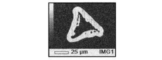
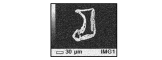
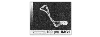
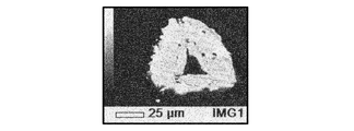
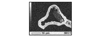
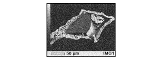
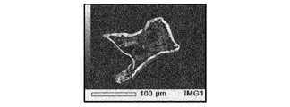
- ⁇ Evaluation> 2A to 2D show the results of observing the cross sections of the skeletons of the nickel alloy porous bodies 1 to 4 obtained above with an electron microscope (SEM). As shown in FIGS. 2A to 2D, in the nickel alloy porous bodies 1 to 4, no additive metal particles remain on the inner surface of the skeleton of the nickel alloy porous body, and the additive metal diffuses uniformly in the nickel. It was confirmed that
- Example 2 In Example 1, instead of nickel-chromium alloy oxide powder, nickel-cobalt alloy oxide powder, nickel-tin alloy oxide powder, and nickel-copper alloy oxide powder, nickel-chromium alloy powder, nickel-cobalt Nickel alloy porous bodies 5 to 8 were produced in the same manner as in Example 1 except that alloy powder, nickel-tin alloy powder, and nickel-copper alloy powder were used. Table 1 shows the volume average particle diameter and the coating weight of each nickel alloy powder. When the cross section of the skeleton of the nickel alloy porous bodies 5 to 8 was observed with an electron microscope in the same manner as in Example 1, no additional metal particles remained on the inner surface of the skeleton of the nickel alloy porous body, and the added metal was nickel. It was confirmed that it diffused uniformly.
- Example 1 In Example 1, instead of nickel-chromium alloy oxide powder, nickel-cobalt alloy oxide powder, nickel-tin alloy oxide powder, and nickel-copper alloy oxide powder, chromium oxide powder, cobalt oxide powder, oxidation Nickel alloy porous bodies 9 to 12 were produced in the same manner as in Example 1 except that tin powder and copper oxide powder were used. In addition, each metal oxide powder used what oxidized and grind
- Example 2 In Example 1, instead of nickel-chromium alloy oxide powder, nickel-cobalt alloy oxide powder, nickel-tin alloy oxide powder, and nickel-copper alloy oxide powder, chromium powder, cobalt powder, tin powder, Further, nickel alloy porous bodies 13 to 16 were produced in the same manner as in Example 1 except that copper powder was used. When the cross section of the skeleton of the nickel alloy porous bodies 13 to 16 was observed with an electron microscope in the same manner as in Example 1, it was confirmed that some of the added metal particles remained on the inner surface of the skeleton of the nickel alloy porous body. It was.
- the metal porous body which is the nickel alloy porous body of the present invention can be suitably used for hydrogen production by water electrolysis in addition to the fuel cell.
- FIG. 4 is a conceptual diagram showing a conventional water splitting apparatus.
- Current collectors 6 are provided at both ends of the ion permeable membrane 5.
- the ion permeable membrane 5 mainly transmits hydrogen or oxygen, and the current collector 6 has a gas flow path composed of a stainless corrugated plate or a grooved carbon structure on the side in contact with the ion permeable membrane. ing. Water vapor is introduced into the gas flow path.
- decomposed hydrogen ions pass through the ion permeable membrane 5 and are discharged from the gas flow path on the opposite side, and the decomposed oxygen remains as it is together with the undecomposed water vapor. Discharged.
- FIG. 5 is a conceptual diagram showing a water splitting apparatus using a porous metal body according to one embodiment of the present invention. Although it differs from the conventional water splitting device of FIG. 4 in that the gas flow path is formed of the porous metal body 7, it has the same configuration in other respects. By forming the gas flow path of the current collector 6 with the metal porous body 7 in this way, hydrogen can be produced by water splitting more efficiently than before.
- the anode and the cathode are immersed in a strong alkaline aqueous solution, and water is electrolyzed by applying a voltage.
- a metal porous body as an electrode, the contact area between water and the electrode is increased, and the efficiency of water electrolysis can be increased.
- the pore diameter of the metal porous body is preferably 100 ⁇ m or more and 5000 ⁇ m or less. If it is smaller than 100 ⁇ m, the generated hydrogen / oxygen bubbles are not easily removed, and the area where water contacts the electrode is reduced, resulting in a reduction in efficiency. On the other hand, if it is larger than 5000 ⁇ m, the surface area of the electrode becomes small, and the efficiency is lowered. From the same viewpoint, it is more preferably 400 ⁇ m or more and 4000 ⁇ m or less.
- the thickness and the amount of metal of the metal porous body may be appropriately selected depending on the scale of the equipment because it causes a deflection or the like when the electrode area increases.
- a plurality of porous metal bodies having different pore diameters can be used in combination in order to achieve both the elimination of bubbles and the securing of the surface area.
- the PEM method (2) is a method in which water is electrolyzed using a solid polymer electrolyte membrane.
- An anode and a cathode are arranged on both sides of the solid polymer electrolyte membrane, and a voltage is applied while flowing water on the anode side.
- hydrogen ions generated by electrolysis of water are moved to the cathode side through the solid polymer electrolyte membrane and taken out as hydrogen on the cathode side.
- the operating temperature is about 100 ° C.
- the polymer electrolyte fuel cell that generates electricity with hydrogen and oxygen and discharges water is operated in exactly the reverse manner with the same configuration. Since the anode side and the cathode side are completely separated, there is an advantage that high purity hydrogen can be taken out. Since both the anode and the cathode must pass through the electrode and allow water and hydrogen gas to pass through, the electrode needs a conductive porous body.
- the metal porous body of the present invention has a high porosity and good electrical conductivity, it can be suitably used for PEM water electrolysis as well as a polymer electrolyte fuel cell. .
- the pore diameter of the metal porous body is preferably 100 ⁇ m or more and 5000 ⁇ m or less. If it is smaller than 100 ⁇ m, the generated hydrogen / oxygen bubbles are not easily removed, and the area where water comes into contact with the solid polymer electrolyte is reduced, thereby lowering the efficiency. On the other hand, if it is larger than 5000 ⁇ m, the water retention property is deteriorated, so that water passes through before sufficiently reacting and the efficiency is lowered. From the same viewpoint, 400 ⁇ m or more and 4000 ⁇ m or less are more preferable.
- the thickness and the amount of metal of the metal porous body may be appropriately selected depending on the scale of the equipment. However, if the porosity is too small, the pressure loss for introducing water increases, so that the porosity is 30% or more. It is preferable to adjust the thickness and the amount of metal. Further, in this method, the electrical connection between the solid polymer electrolyte and the electrode is a pressure bonding. Therefore, it is necessary to adjust the amount of metal so that the increase in electric resistance due to deformation and creep during pressurization is within a practically acceptable range.
- the amount of metal is preferably 400 g / m 2 or more.
- a plurality of porous metal bodies having different pore diameters can be used in combination for ensuring porosity and electrical connection.
- the SOEC method (3) is a method in which water is electrolyzed using a solid oxide electrolyte membrane, and the configuration differs depending on whether the electrolyte membrane is proton conduction or oxygen ion conduction.
- oxygen ion conductive membrane hydrogen is generated on the cathode side where water vapor is introduced, so that the hydrogen purity is lowered. Therefore, a proton conductive membrane is preferable from the viewpoint of hydrogen production.
- the operating temperature is about 600 ° C to 800 ° C.
- a solid oxide fuel cell that generates electricity with hydrogen and oxygen and discharges water is operated in exactly the reverse manner with the same configuration. Since both the anode and the cathode need to pass through the electrode and allow water vapor / hydrogen gas to pass through, the electrode needs to be conductive and have a porous body that can withstand a high-temperature oxidizing atmosphere, particularly on the anode side.
- the porous metal body of the present invention has high porosity, good electrical conductivity, and high oxidation resistance and heat resistance, it can be used in a solid oxide fuel cell as in the SOEC system. It can also be suitably used for water electrolysis. It is preferable to use a Ni alloy to which a metal having high oxidation resistance such as Cr is added for the electrode on the side that becomes an oxidizing atmosphere.
- the pore diameter of the metal porous body is preferably 100 ⁇ m or more and 5000 ⁇ m or less. If it is smaller than 100 ⁇ m, the passage of water vapor and generated hydrogen becomes worse, the area where the water vapor contacts the solid oxide electrolyte is reduced, and the efficiency is lowered. Moreover, since pressure loss will become low too much when it is larger than 5000 micrometers, before water vapor
- the thickness of the metal porous body and the amount of metal may be appropriately selected depending on the scale of the equipment. However, if the porosity is too small, the pressure loss for introducing water vapor increases, so that the porosity is 30% or more. It is preferable to adjust the thickness and the amount of metal. Further, in this method, since the electrical connection between the solid oxide electrolyte and the electrode is a pressure bonding, it is necessary to adjust the amount of metal so that the increase in electric resistance due to deformation and creep during pressurization is within a practical range.
- the amount of metal is preferably 400 g / m 2 or more.
- a plurality of porous metal bodies having different pore diameters can be used in combination for ensuring porosity and electrical connection.
- -Additional notes- Applying a paint containing nickel alloy powder of nickel and an additive metal to the surface of the skeleton of the resin molded body having a three-dimensional network structure; A step of plating nickel on the surface of the skeleton of the resin molded body to which the paint is applied; Removing the resin molded body; Diffusing the additive metal into the nickel by heat treatment; A current collector comprising a nickel alloy porous body manufactured by: A water splitting device comprising an ion permeable membrane having the current collector at both ends.
- the nickel alloy porous body is: Applying a paint containing nickel alloy powder of nickel and an additive metal to the surface of the skeleton of the resin molded body having a three-dimensional network structure; A step of plating nickel on the surface of the skeleton of the resin molded body to which the paint is applied; Removing the resin molded body; Diffusing the additive metal into the nickel by heat treatment, and A step of forming an ion permeable membrane having the current collector at both ends; A step of introducing water vapor into the current collector and taking out hydrogen that has permeated through the ion permeable membrane.
- the nickel alloy porous body of the present invention is excellent in mechanical properties and corrosion resistance, and can be kept low in cost. Therefore, it can be suitably used for a current collector of a secondary battery such as a lithium ion battery, a capacitor, or a fuel cell, and a water splitting device.
- a secondary battery such as a lithium ion battery, a capacitor, or a fuel cell
Landscapes
- Chemical & Material Sciences (AREA)
- Engineering & Computer Science (AREA)
- Materials Engineering (AREA)
- Metallurgy (AREA)
- Organic Chemistry (AREA)
- Chemical Kinetics & Catalysis (AREA)
- Electrochemistry (AREA)
- Mechanical Engineering (AREA)
- Powder Metallurgy (AREA)
- Inert Electrodes (AREA)
- Fuel Cell (AREA)
- Electroplating Methods And Accessories (AREA)
Priority Applications (5)
| Application Number | Priority Date | Filing Date | Title |
|---|---|---|---|
| US15/550,474 US20180030607A1 (en) | 2015-02-18 | 2016-01-22 | Method for producing nickel alloy porous body |
| KR1020177019564A KR20170118701A (ko) | 2015-02-18 | 2016-01-22 | 니켈 합금 다공체의 제조 방법 |
| JP2017500565A JP6653313B2 (ja) | 2015-02-18 | 2016-01-22 | ニッケル合金多孔体の製造方法 |
| CN201680010206.XA CN107208294B (zh) | 2015-02-18 | 2016-01-22 | 镍合金多孔体的制造方法 |
| EP16752200.2A EP3260579B1 (de) | 2015-02-18 | 2016-01-22 | Verfahren zur herstellung von porösem nickellegierungskörper |
Applications Claiming Priority (2)
| Application Number | Priority Date | Filing Date | Title |
|---|---|---|---|
| JP2015029654 | 2015-02-18 | ||
| JP2015-029654 | 2015-02-18 |
Publications (1)
| Publication Number | Publication Date |
|---|---|
| WO2016132811A1 true WO2016132811A1 (ja) | 2016-08-25 |
Family
ID=56688791
Family Applications (1)
| Application Number | Title | Priority Date | Filing Date |
|---|---|---|---|
| PCT/JP2016/051784 Ceased WO2016132811A1 (ja) | 2015-02-18 | 2016-01-22 | ニッケル合金多孔体の製造方法 |
Country Status (6)
| Country | Link |
|---|---|
| US (1) | US20180030607A1 (de) |
| EP (1) | EP3260579B1 (de) |
| JP (1) | JP6653313B2 (de) |
| KR (1) | KR20170118701A (de) |
| CN (1) | CN107208294B (de) |
| WO (1) | WO2016132811A1 (de) |
Cited By (4)
| Publication number | Priority date | Publication date | Assignee | Title |
|---|---|---|---|---|
| WO2019244480A1 (ja) * | 2018-06-21 | 2019-12-26 | 住友電気工業株式会社 | 多孔体、それを含む集電体および燃料電池 |
| WO2020235266A1 (ja) * | 2019-05-22 | 2020-11-26 | 住友電気工業株式会社 | 多孔体、それを含む燃料電池、およびそれを含む水蒸気電解装置 |
| JPWO2021130849A1 (de) * | 2019-12-24 | 2021-07-01 | ||
| CN114761593A (zh) * | 2019-12-24 | 2022-07-15 | 住友电气工业株式会社 | 多孔体和包含所述多孔体的燃料电池 |
Families Citing this family (4)
| Publication number | Priority date | Publication date | Assignee | Title |
|---|---|---|---|---|
| CN113474493B (zh) * | 2019-03-01 | 2024-07-05 | 田中贵金属工业株式会社 | 多孔体、电化学电池和多孔体的制造方法 |
| US20220320530A1 (en) * | 2019-05-22 | 2022-10-06 | Sumitomo Electric Industries, Ltd. | Porous body, fuel cell including the same, and steam electrolysis apparatus including the same |
| CN116037958B (zh) * | 2022-12-30 | 2024-08-16 | 吉林大学 | 仿鱼鳍高强高韧航空壳体、航空材料及其制备方法 |
| CN117926304B (zh) * | 2023-06-30 | 2024-12-17 | 国家能源投资集团有限责任公司 | 一种碱性电解水膜电极及其制备方法和电解槽 |
Citations (3)
| Publication number | Priority date | Publication date | Assignee | Title |
|---|---|---|---|---|
| JPH07150270A (ja) * | 1993-11-30 | 1995-06-13 | Sumitomo Electric Ind Ltd | 金属多孔質材、その製造方法およびそれを用いた電池用電極 |
| JP2003147570A (ja) * | 2001-11-08 | 2003-05-21 | Sumitomo Electric Ind Ltd | 微細金属部品の製造方法 |
| JP2013133504A (ja) * | 2011-12-27 | 2013-07-08 | Toyama Sumitomo Denko Kk | 金属多孔体の製造方法及び金属多孔体 |
Family Cites Families (1)
| Publication number | Priority date | Publication date | Assignee | Title |
|---|---|---|---|---|
| JP5952149B2 (ja) * | 2012-09-27 | 2016-07-13 | 住友電気工業株式会社 | 金属多孔体及びその製造方法 |
-
2016
- 2016-01-22 JP JP2017500565A patent/JP6653313B2/ja not_active Expired - Fee Related
- 2016-01-22 KR KR1020177019564A patent/KR20170118701A/ko not_active Withdrawn
- 2016-01-22 WO PCT/JP2016/051784 patent/WO2016132811A1/ja not_active Ceased
- 2016-01-22 US US15/550,474 patent/US20180030607A1/en not_active Abandoned
- 2016-01-22 CN CN201680010206.XA patent/CN107208294B/zh not_active Expired - Fee Related
- 2016-01-22 EP EP16752200.2A patent/EP3260579B1/de not_active Not-in-force
Patent Citations (3)
| Publication number | Priority date | Publication date | Assignee | Title |
|---|---|---|---|---|
| JPH07150270A (ja) * | 1993-11-30 | 1995-06-13 | Sumitomo Electric Ind Ltd | 金属多孔質材、その製造方法およびそれを用いた電池用電極 |
| JP2003147570A (ja) * | 2001-11-08 | 2003-05-21 | Sumitomo Electric Ind Ltd | 微細金属部品の製造方法 |
| JP2013133504A (ja) * | 2011-12-27 | 2013-07-08 | Toyama Sumitomo Denko Kk | 金属多孔体の製造方法及び金属多孔体 |
Non-Patent Citations (1)
| Title |
|---|
| See also references of EP3260579A4 * |
Cited By (12)
| Publication number | Priority date | Publication date | Assignee | Title |
|---|---|---|---|---|
| WO2019244480A1 (ja) * | 2018-06-21 | 2019-12-26 | 住友電気工業株式会社 | 多孔体、それを含む集電体および燃料電池 |
| JPWO2019244480A1 (ja) * | 2018-06-21 | 2021-05-13 | 住友電気工業株式会社 | 多孔体、それを含む集電体および燃料電池 |
| US11329295B2 (en) | 2018-06-21 | 2022-05-10 | Sumitomo Electric Industries, Ltd. | Porous body, current collector including the same, and fuel cell |
| JP7230826B2 (ja) | 2018-06-21 | 2023-03-01 | 住友電気工業株式会社 | 多孔体、それを含む集電体および燃料電池 |
| WO2020235266A1 (ja) * | 2019-05-22 | 2020-11-26 | 住友電気工業株式会社 | 多孔体、それを含む燃料電池、およびそれを含む水蒸気電解装置 |
| JPWO2021130849A1 (de) * | 2019-12-24 | 2021-07-01 | ||
| WO2021130849A1 (ja) * | 2019-12-24 | 2021-07-01 | 住友電気工業株式会社 | 多孔体、およびそれを含む燃料電池 |
| CN113383100A (zh) * | 2019-12-24 | 2021-09-10 | 住友电气工业株式会社 | 多孔体以及包括该多孔体的燃料电池 |
| CN114761593A (zh) * | 2019-12-24 | 2022-07-15 | 住友电气工业株式会社 | 多孔体和包含所述多孔体的燃料电池 |
| CN113383100B (zh) * | 2019-12-24 | 2022-10-25 | 住友电气工业株式会社 | 多孔体以及包括该多孔体的燃料电池 |
| JP7314940B2 (ja) | 2019-12-24 | 2023-07-26 | 住友電気工業株式会社 | 多孔体、およびそれを含む燃料電池 |
| US11757106B2 (en) | 2019-12-24 | 2023-09-12 | Sumitomo Electric Industries, Ltd. | Porous body and fuel cell including the same |
Also Published As
| Publication number | Publication date |
|---|---|
| CN107208294A (zh) | 2017-09-26 |
| EP3260579A4 (de) | 2018-01-24 |
| US20180030607A1 (en) | 2018-02-01 |
| EP3260579B1 (de) | 2018-10-17 |
| CN107208294B (zh) | 2019-07-30 |
| KR20170118701A (ko) | 2017-10-25 |
| EP3260579A1 (de) | 2017-12-27 |
| JPWO2016132811A1 (ja) | 2017-11-24 |
| JP6653313B2 (ja) | 2020-02-26 |
Similar Documents
| Publication | Publication Date | Title |
|---|---|---|
| JP6653313B2 (ja) | ニッケル合金多孔体の製造方法 | |
| EP2666890B1 (de) | Poröses metall mit hoher korrosionsbeständigkeit und verfahren zu seiner herstellung | |
| EP2600968B1 (de) | Verwendung eines Platinlegierungskatalysators für Brennstoffzellen | |
| JP6614131B2 (ja) | 多孔質集電体、燃料電池及び多孔質集電体の製造方法 | |
| JP6300315B2 (ja) | 燃料電池用集電体及び燃料電池 | |
| WO2013099532A1 (ja) | 金属多孔体の製造方法及び金属多孔体 | |
| JP6628057B2 (ja) | 金属多孔体、燃料電池、及び金属多孔体の製造方法 | |
| JP2017054797A (ja) | 金属多孔体、燃料電池、及び金属多孔体の製造方法 | |
| JP2017033917A (ja) | 金属多孔体、燃料電池、及び金属多孔体の製造方法 | |
| JPWO2020049851A1 (ja) | 金属多孔体、燃料電池および金属多孔体の製造方法 | |
| CN110870117B (zh) | 金属多孔体、固体氧化物型燃料电池以及金属多孔体的制造方法 | |
| WO2017043365A1 (ja) | 金属多孔体、燃料電池、及び金属多孔体の製造方法 | |
| WO2017022542A1 (ja) | 金属多孔体、燃料電池、及び金属多孔体の製造方法 | |
| JP4066154B2 (ja) | すぐれた接面通電性を長期に亘って発揮する固体高分子形燃料電池の多孔質金属ガス拡散シート | |
| CN110870116A (zh) | 金属多孔体、固体氧化物型燃料电池以及金属多孔体的制造方法 | |
| JP2004047125A (ja) | すぐれた接面通電性を長期に亘って発揮する固体高分子形燃料電池の多孔質金属ガス拡散シート | |
| JP2004047126A (ja) | すぐれた接面通電性を長期に亘って発揮する固体高分子形燃料電池の多孔質金属ガス拡散シート | |
| JP4066155B2 (ja) | すぐれた接面通電性を長期に亘って発揮する固体高分子形燃料電池の多孔質金属ガス拡散シート |
Legal Events
| Date | Code | Title | Description |
|---|---|---|---|
| 121 | Ep: the epo has been informed by wipo that ep was designated in this application |
Ref document number: 16752200 Country of ref document: EP Kind code of ref document: A1 |
|
| ENP | Entry into the national phase |
Ref document number: 2017500565 Country of ref document: JP Kind code of ref document: A |
|
| ENP | Entry into the national phase |
Ref document number: 20177019564 Country of ref document: KR Kind code of ref document: A |
|
| REEP | Request for entry into the european phase |
Ref document number: 2016752200 Country of ref document: EP |
|
| NENP | Non-entry into the national phase |
Ref country code: DE |