WO2016132848A1 - Dispositif d'aide à la conduite et procédé d'aide à la conduite - Google Patents
Dispositif d'aide à la conduite et procédé d'aide à la conduite Download PDFInfo
- Publication number
- WO2016132848A1 WO2016132848A1 PCT/JP2016/052506 JP2016052506W WO2016132848A1 WO 2016132848 A1 WO2016132848 A1 WO 2016132848A1 JP 2016052506 W JP2016052506 W JP 2016052506W WO 2016132848 A1 WO2016132848 A1 WO 2016132848A1
- Authority
- WO
- WIPO (PCT)
- Prior art keywords
- driver
- override
- driving
- vehicle
- switching
- Prior art date
- Legal status (The legal status is an assumption and is not a legal conclusion. Google has not performed a legal analysis and makes no representation as to the accuracy of the status listed.)
- Ceased
Links
Images


Classifications
-
- B—PERFORMING OPERATIONS; TRANSPORTING
- B60—VEHICLES IN GENERAL
- B60W—CONJOINT CONTROL OF VEHICLE SUB-UNITS OF DIFFERENT TYPE OR DIFFERENT FUNCTION; CONTROL SYSTEMS SPECIALLY ADAPTED FOR HYBRID VEHICLES; ROAD VEHICLE DRIVE CONTROL SYSTEMS FOR PURPOSES NOT RELATED TO THE CONTROL OF A PARTICULAR SUB-UNIT
- B60W50/00—Details of control systems for road vehicle drive control not related to the control of a particular sub-unit, e.g. process diagnostic or vehicle driver interfaces
- B60W50/08—Interaction between the driver and the control system
- B60W50/12—Limiting control by the driver depending on vehicle state, e.g. interlocking means for the control input for preventing unsafe operation
-
- G—PHYSICS
- G08—SIGNALLING
- G08G—TRAFFIC CONTROL SYSTEMS
- G08G1/00—Traffic control systems for road vehicles
- G08G1/16—Anti-collision systems
Definitions
- This disclosure relates to a driving support technology for switching between automatic driving and manual driving.
- a technology for automatically driving a vehicle is known.
- a technology is known in which automatic driving is canceled and switched to manual driving by a driving operation (hereinafter referred to as “override”) by a driver during automatic driving.
- Patent Document 1 discloses a technique for switching from automatic driving to manual driving when an override such as a steering operation, a brake operation, or an accelerator operation by a driver is detected during automatic driving.
- This disclosure is intended to provide a driving support technology that suppresses switching from automatic driving to manual driving by an override that is not suitable for the situation in which the vehicle is placed.
- the driving support device of the present disclosure is mounted on a vehicle that performs automatic driving, and includes driving switching means for switching from automatic driving to manual driving, and override detection means for detecting an override by a driver, and the override detection means detects an override.
- the operation switching unit is a driving support device that switches from automatic operation to manual operation, and includes a driver state determination unit that sequentially determines whether or not the driver lacks concentration. Even if the override is detected by the override detection means, if the driver state determination means determines that the driver lacks concentration, the automatic operation is not switched to the manual operation.
- the driving support device of the present disclosure does not switch from the automatic driving to the manual driving if it is determined that the driver lacks concentration even if the driver override is detected. Therefore, even when the driver of the vehicle lacks concentration, even if an override that is not suitable for the situation in which the vehicle is placed is performed, it is not necessary to switch from automatic operation to manual operation. As a result, the driving support device according to the present disclosure can suppress switching from automatic driving to manual driving due to an override that is not suitable for the situation where the vehicle is placed.
- FIG. 1 is a block diagram illustrating an example of a schematic configuration of the driving support system according to the first embodiment.
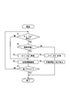
- FIG. 2 is a flowchart illustrating an example of a flow of override-related processing by the driving support apparatus according to the first embodiment.
- FIG. 3 is a block diagram illustrating an example of a schematic configuration of a driving support system according to a modification.
- FIG. 1 is a block diagram illustrating an example of a schematic configuration of a driving support system 100 to which the driving support device according to the present disclosure is applied.
- the driving support system 100 includes a driving support device 1, a surrounding environment recognition device 2, a vehicle behavior related sensor 3, and a brake switch 4.
- the driving support system 100 includes an accelerator switch 5, a steering torque sensor 6, a vehicle interior camera 7, and a vehicle control ECU 8, and is mounted on the vehicle.
- a vehicle equipped with the driving support system 100 is referred to as a host vehicle.
- the surrounding environment recognition device 2 includes a sensor such as a camera or a laser radar that images a predetermined range around the host vehicle.
- the surrounding environment recognition device 2 recognizes the surrounding environment of the host vehicle based on the detection information of the sensor. Examples of the surrounding environment to be recognized include a road shape around the host vehicle, a preceding vehicle located in front of the host vehicle, and an obstacle around the host vehicle.
- the surrounding environment recognition device 2 performs image recognition processing such as edge detection on the captured image of the camera. Thereby, the surrounding environment recognition apparatus 2 recognizes the lane of a road.
- the surrounding environment recognition device 2 calculates the lane width of the recognized lane, the radius of curvature of the lane, the offset amount of the host vehicle from the lane center, and the like. Thereby, the surrounding environment recognition apparatus 2 recognizes the road shape around the own vehicle.
- the surrounding environment recognition device 2 performs image recognition processing such as edge detection and template matching on the image captured by the camera. Thereby, the surrounding environment recognition device 2 specifies the size of the preceding vehicle, the size of the obstacle around the host vehicle, and the relative position with the host vehicle. And the surrounding environment recognition apparatus 2 specifies the moving speed and moving direction of a preceding vehicle or an obstruction based on the temporal change rate of the relative position of the own vehicle with respect to the specified preceding vehicle or an obstruction. In addition, when the surrounding environment recognition device 2 uses a laser radar, a millimeter wave radar, or a sonar, the surrounding environment recognition device 2 detects a preceding vehicle or an obstacle based on the received intensity of the reflected wave generated by reflecting the transmitted exploration wave on the object. What is necessary is just to detect.
- the surrounding environment recognition device 2 When the exploration wave can be scanned, the surrounding environment recognition device 2 identifies the direction of the preceding vehicle and the obstacle with respect to the own vehicle from the transmission direction of the exploration wave corresponding to the reflected wave. And the surrounding environment recognition apparatus 2 determines the distance from the own vehicle to a preceding vehicle and an obstruction based on the specified direction and the time from when the exploration wave is transmitted until the reflected wave is received. Further, in the case of a radar, the surrounding environment recognition device 2 may be configured to determine the relative position of a preceding vehicle or an obstacle with respect to the own vehicle using an amplitude comparison monopulse type radar or a phase comparison monopulse type radar.
- the relative speed of the preceding vehicle and the obstacle with respect to the host vehicle may be determined by a predetermined method based on the Doppler shift between the exploration wave and the reflected wave. Moreover, it is good also as a structure determined based on the temporal change rate of the relative position with respect to the own vehicle of the preceding vehicle and obstacle which are determined sequentially.
- the vehicle behavior related sensor 3 detects information related to the behavior of the host vehicle (hereinafter referred to as “vehicle behavior information”).
- vehicle behavior information includes a vehicle speed sensor, an acceleration sensor, and a gyro sensor.
- the vehicle speed sensor detects the vehicle speed of the host vehicle.
- the acceleration sensor detects the acceleration of the host vehicle.
- the gyro sensor detects the angular velocity of the host vehicle.
- Other vehicle behavior related sensors 3 include a receiver that receives information capable of calculating the position of the vehicle from a positioning satellite of a positioning satellite system.
- the brake switch 4 is a switch that is turned on when the brake pedal of the host vehicle is depressed, and turned off when the brake pedal is not depressed.
- the brake switch 4 outputs a signal corresponding to on / off.
- the accelerator switch 5 is a switch that is turned on when the accelerator pedal of the host vehicle is depressed, and turned off when the accelerator pedal is not depressed.
- the accelerator switch 5 outputs a signal corresponding to on / off.
- the steering torque sensor 6 detects the steering torque applied to the steering wheel of the host vehicle by the driving operation of the driver.
- the vehicle interior camera 7 corresponds to a biological information sensor, and is a sensor that senses a driver to determine whether or not the driver who is in the vehicle is in a state of lacking concentration (a state in which concentration is reduced). Function as.
- the vehicle interior camera 7 sequentially captures a predetermined range (predetermined imaging region) including the face of the driver who is in the host vehicle at predetermined time intervals (for example, at 100 msec intervals).
- the vehicle interior camera 7 may be installed at a position where a predetermined range including the driver's face, such as the upper surface of the steering column cover, can be imaged.
- the vehicle interior camera 7 may be an optical camera or an infrared camera that can capture images even in an environment with little visible light.
- the vehicle control ECU 8 is an electronic control device that performs speed control (acceleration / deceleration control) and steering control of the host vehicle.
- Examples of the vehicle control ECU 8 include a steering ECU, an engine ECU, and a brake ECU.
- the steering ECU performs steering control of the host vehicle.
- the engine ECU and the brake ECU perform speed control of the host vehicle including acceleration / deceleration.
- the driving support device 1 includes a CPU, a memory (ROM, RAM, etc.), and an I / O, which are connected via a bus.
- the CPU executes a program stored in the memory.
- the driving assistance apparatus 1 the process for implement
- the driving support device 1 is provided with a driving support function for switching between automatic driving and manual driving.
- an instruction signal is output to the vehicle control ECU 8 to instruct execution of automatic driving.
- the driving support device 1 switches from automatic driving to manual driving based on the detection result of the driving operation (hereinafter referred to as “override”) by the driver during automatic driving. Details of these driving support devices 1 will be described later.
- the driving support apparatus 1 may be configured to realize part or all of the functions provided by the execution of the program by one or a plurality of hardware (for example, ICs).
- the driving support apparatus 1 includes an automatic driving control unit 11, an override detection unit 12, a driver state determination unit 13, an availability determination unit 14, and a driving switching unit 15.
- the automatic driving control unit 11 Based on the detection information of the surrounding environment of the host vehicle recognized by the surrounding environment recognition device 2 and the vehicle behavior information of the host vehicle detected by the vehicle behavior related sensor 3, the automatic driving control unit 11 performs the target travel at the time of automatic driving. Determine the course and target speed. Then, the automatic operation control unit 11 outputs an instruction signal for automatic operation to the vehicle control ECU 8 based on the determined target travel route and target travel speed. As a result, the vehicle control ECU 8 changes the vehicle steering angle, the brake pressure, the intake air amount, the gear ratio, etc. according to the input instruction signal, and automatically operates so that the host vehicle travels at the target travel path and the target travel speed. Control. As an example of automatic driving, there are automatic driving that keeps the traveling lane of the own vehicle on an expressway, automatic driving that retreats to the road shoulder when the own vehicle is abnormal, automatic driving that follows the preceding vehicle, etc. is there.
- the override detection unit 12 detects an override during automatic operation. That is, the override detection unit 12 functions as an override detection unit that detects an override by the driver.
- the override detection unit 12 according to the present embodiment detects the following driving operation by the driver as an override. For example, the override detection unit 12 detects a brake operation by the driver as an override when the brake switch 4 is on.
- the override detection unit 12 detects an accelerator operation by the driver as an override when the accelerator switch 5 is on.
- the override detection unit 12 detects a steering operation by the driver as an override based on the steering torque detected by the steering torque sensor 6.
- the detection of the brake operation and the accelerator operation by the driver is not limited to the detection method based on the on / off state of the brake switch 4 and the accelerator switch 5.
- the brake operation by the driver may be detected based on a signal from a brake stroke sensor that detects the depression amount of the brake pedal.
- the accelerator operation by the driver may be detected based on a signal from an accelerator stroke sensor that detects the amount of depression of the accelerator pedal.
- the driver state determination unit 13 sequentially determines at predetermined time intervals whether or not the driver who is in the vehicle is in a state where the driver lacks concentration (a state where concentration is reduced). That is, the driver state determination unit 13 functions as a driver state determination unit that sequentially determines whether or not the driver lacks concentration.
- the driver state determination unit 13 is based on a captured image including the driver's face of the host vehicle captured by the in-vehicle camera 7 (hereinafter referred to as “face image”). It is sequentially determined whether or not.
- face image a captured image including the driver's face of the host vehicle captured by the in-vehicle camera 7
- the driver state determination unit 13 detects the pupil and corneal reflection of the driver through image recognition processing of the face image captured by the vehicle interior camera 7.
- the driver state determination unit 13 detects the direction of the driver's line of sight based on the positional relationship between the detected pupil and corneal reflection.
- the driver state determination unit 13 determines that the driver is looking aside when the direction of the detected line of sight deviates more than a predetermined angle from the front of the traveling direction of the host vehicle.
- the predetermined angle mentioned here is a value that can be determined that the driver is looking aside and can be arbitrarily set.
- the driver state determination unit 13 detects the direction of the driver's face, not the direction of the driver's line of sight, by image recognition processing of the face image captured by the vehicle interior camera 7.
- the driver state determination unit 13 may determine that the driver is looking aside when the detected face orientation deviates more than a predetermined angle from the front in the traveling direction of the host vehicle. Good.
- the driver state determination unit 13 performs predetermined image processing on the face image captured by the vehicle interior camera 7, and based on the image processing result (face image after image processing), the degree of eye opening of the driver's eyes (For example, the ratio of the period when the eyes are closed) is detected.
- the driver state determination unit 13 may determine that the driver is in a sleepy state based on the detected degree of eye opening.
- the degree of eye opening (threshold for determination) determined to be a sloppy state may be a value that can determine the drowsiness of the driver, and can be arbitrarily set.
- the availability determination unit 14 determines the validity (valid or invalid) of the override detected during the automatic operation.
- the override detection unit 12 detects an override
- the propriety determination unit 14 determines that the detected override is invalid if the driver state determination unit 13 determines that the state is a random state.
- the override detection unit 12 detects an override
- the propriety determination unit 14 determines that the detected override is valid if the driver state determination unit 13 does not determine that it is in a random state. That is, when the override is detected, the availability determination unit 14 determines whether the override is valid (valid or invalid) depending on whether or not the driver has determined that the driver is in a loose state (a state that lacks concentration). It functions as an availability determination means.
- the operation switching unit 15 switches between automatic operation and manual operation. That is, the operation switching unit 15 functions as an operation switching unit that switches from automatic operation to manual operation.
- the driving switching unit 15 receives a switching instruction between automatic driving and manual driving from a driver via, for example, an operation input unit provided on the steering of the host vehicle.
- the driving switching unit 15 outputs an instruction signal for switching from manual driving to automatic driving to the vehicle control ECU 8 when an operation input for instructing automatic driving is received from the driver.
- the driving switching unit 15 outputs an instruction signal for switching from automatic driving to manual driving to the vehicle control ECU 8 when receiving an operation input for instructing manual driving from the driver.
- operation switching part 15 outputs the instruction
- the override related process is a process related to an override during automatic driving of the host vehicle.
- FIG. 2 for example, when the automatic driving control unit 11 starts automatic driving of the host vehicle, an example of processing in the case of starting execution of the override related processing is shown.
- the driving support device 1 detects the override by the driver during automatic driving by the override detection unit 12 (step S1). As a result, when the override detection unit 12 detects an override (step S1: YES), the driving support device 1 proceeds to the process of step S2. On the other hand, when the override detection unit 12 has not detected an override (step S1: NO), the driving support device 1 proceeds to the process of step S4.
- step S1 the driving assistance device 1 acquires the determination result of the driver's indecent state (a state lacking concentration) that is sequentially determined by the driver state determination unit 13 (step S2). ).
- step S2 the driver state determination unit 13 determines that the driver's state is a loose state
- step S3 the driving support device 1 proceeds to the process of step S3.
- step S2 NO
- step S3 When the driving support device 1 makes an affirmative determination in the process of step S2, the availability determination unit 14 determines that the override detected by the override detection unit 12 is invalid (step S3). And the driving assistance apparatus 1 continues an automatic driving
- the driving support device 1 determines whether it is the end timing of the override related process after the process of step S4 (step S7). As a result, when it is determined that it is the end timing (step S7: YES), the driving support device 1 ends the override related process. On the other hand, when it determines with the driving assistance apparatus 1 not being the completion
- the end timing of the override-related processing include when the ignition power of the host vehicle is turned off or when an operation input for instructing manual driving is received from the driver via the operation input unit. .
- the driver state determination unit 13 determines whether or not the driver's state is loose.
- the availability determination unit 14 does not determine the validity (valid or invalid) of the detected override.
- the propriety determination unit 14 is based on the determination result of the driver's random state that is sequentially determined by the driver state determination unit 13. Determines the validity of the detected override. In other words, in this embodiment, every time an override is detected, it is not determined whether or not the driver is in a random state.
- the driving assistance apparatus 1 when an override is detected, the latest determination result as to whether or not the driver is in a random state is obtained. Therefore, in the driving assistance apparatus 1 according to the present embodiment, it is possible to reduce a delay in timing from when the override detection unit 12 detects the override until the automatic driving is switched to the manual driving.
- the driver state determination unit 13 sequentially determines the presence or absence of a sloppy state such as a driver's side-view or doze.
- the driver state determination unit 13 determines that the driver state is in a loose state. If it is, switch from automatic operation to manual operation. More specifically, in the driving support device 1, the availability determination unit 14 determines that the detected override is invalid, and does not cause the driving switching unit 15 to switch from automatic driving to manual driving. Thereby, in the driving assistance apparatus 1 which concerns on this embodiment, it becomes possible to suppress the switch from the automatic driving
- the driver state determination unit 13 determines whether or not the driver's state is indiscriminate.
- the method for determining the driver's mood state is not limited to this.
- a configuration in which it is determined whether or not the driver is in a sloppy state using a detection result of a biological information sensor other than the vehicle interior camera 7 hereinafter, this configuration is referred to as “variation 1”. It is good also as.
- the driving support system 200 according to the first modification includes a driving support device 1a, a surrounding environment recognition device 2, a vehicle behavior related sensor 3, and a brake switch 4.
- the driving support system 200 includes an accelerator switch 5, a steering torque sensor 6, a vehicle interior camera 7, a vehicle control ECU 8, and a heart rate sensor 9.
- the driving support system 200 according to the first modification includes the driving support system 200 according to the first embodiment, except that the driving support system 200 includes the heart rate sensor 9 and the driving support apparatus 1a instead of the driving support apparatus 1. 100.
- the heart rate sensor 9 measures the heart rate of the driver.
- the modification 1 shows an example in which the heart rate sensor 9 is used in addition to the in-vehicle camera 7 as a biological information sensor for determining the driver's mood state
- the configuration of the biological information sensor to be used is not limited to this.
- a pulse sensor that measures a pulse rate, a respiratory sensor that measures a respiration rate, or the like may be used.
- the driving support apparatus 1 a according to the first modification includes an automatic driving control unit 11, an override detection unit 12, a driver state determination unit 13 a, an availability determination unit 14, and a driving switching unit 15.
- the driving support device 1a according to the first modification is the same as the driving support device 1 according to the first embodiment, except that a driver state determination unit 13a is provided instead of the driver state determination unit 13.
- the driver state determination unit 13a according to Modification 1 determines whether or not the driver state is a loose state based on the driver's heart rate sequentially detected by the heart rate sensor 9 in addition to the driver's face image captured by the vehicle interior camera 7. Determine whether. Except for this point, the driver state determination unit 13a according to the first modification is the same as the driver state determination unit 13 according to the first embodiment. For example, the driver state determination unit 13a according to the first modification determines whether or not the driver state is an ambiguous state as follows. Based on the driver's face image captured by the vehicle interior camera 7, the driver state determination unit 13a determines a casual state such as an aside look. In addition, the driver state determination unit 13a determines a casual state such as falling asleep based on the heart rate of the driver measured by the heart rate sensor 9.
- the driver's casual state is determined based on the detection results of a plurality of types of biological information sensors.
- the driving assistance device 1a according to the first modification it is possible to determine the driver's casual state that cannot be determined by only one type of biological information sensor.
- Modification 2 Further, as another modified example (modified example 2), it is determined whether or not the driver is in a loose state using the detection result of the biological information sensor other than the vehicle interior camera 7 without using the vehicle interior camera 7. It is good also as a structure which the part 13 determines. More specifically, in the second modification, for example, the direction of the driver's face is estimated based on the detection result of an acceleration sensor or a gyro sensor provided in an instrument attached to the driver's face. And in the modification 2, it is determined based on an estimation result whether a driver is in an abusive state.
- Modification 3 As another modified example (modified example 3), based on the determination result of the consistency between the override detected by the override detection unit 12 and the state of the driver detected by the biological information sensor, the driver state determination unit 13, 13a is good also as a structure which determines the driver's vague state of the own vehicle.
- the override detection unit 12 detects a steering operation of the host vehicle by the driver as an override. Therefore, in the third modification, the driver's line-of-sight direction or face direction recognized by the image recognition processing of the face image captured by the vehicle interior camera 7 does not match the steering operation direction detected by the override detection unit 12.
- the driver state determination units 13 and 13a may determine that the state of the driver is a random state.
- Modification 4 As another modification (Modification 4), after the override detection unit 12 detects an override, the driver state determination units 13 and 13a determine the driver's casual state. And in the modification 4, it is good also as a structure in which the determination part 14 determines the validity (valid or invalid) of the detected override based on the determination result of a casual state.
- driving support devices 1 and 1a of the present disclosure are not limited to the above-described embodiment, and various modifications can be made within the technical scope of the present disclosure. Further, the driving assistance devices 1 and 1a of the present disclosure also include embodiments obtained by appropriately combining the technical means disclosed in the above-described embodiments within the technical scope of the present disclosure.
Landscapes
- Engineering & Computer Science (AREA)
- Automation & Control Theory (AREA)
- Physics & Mathematics (AREA)
- General Physics & Mathematics (AREA)
- Human Computer Interaction (AREA)
- Transportation (AREA)
- Mechanical Engineering (AREA)
- Traffic Control Systems (AREA)
- Control Of Driving Devices And Active Controlling Of Vehicle (AREA)
Abstract
La présente invention concerne un dispositif d'aide à la conduite (1) équipé : d'une unité de commutation (15) qui commute d'une conduite automatique à une conduite manuelle ; d'une unité de détection (12) qui détecte une annulation effectuée par le conducteur ; et d'une unité de détermination (13) qui détermine successivement si le conducteur est dans un état d'inattention. Lorsque l'unité de détection (12) détecte une annulation et l'unité de détermination (13) a déterminé que le conducteur n'était pas dans un état d'inattention, l'unité de commutation (15) commute de la conduite automatique à la conduite manuelle. Lorsque l'unité de détection (12) détecte une annulation, mais l'unité de détermination (13) a déterminé que le conducteur était dans un état d'inattention, l'unité de commutation (15) ne commute pas de la conduite automatique à la conduite manuelle.
Applications Claiming Priority (2)
| Application Number | Priority Date | Filing Date | Title |
|---|---|---|---|
| JP2015-027765 | 2015-02-16 | ||
| JP2015027765A JP2016151815A (ja) | 2015-02-16 | 2015-02-16 | 運転支援装置 |
Publications (1)
| Publication Number | Publication Date |
|---|---|
| WO2016132848A1 true WO2016132848A1 (fr) | 2016-08-25 |
Family
ID=56692074
Family Applications (1)
| Application Number | Title | Priority Date | Filing Date |
|---|---|---|---|
| PCT/JP2016/052506 Ceased WO2016132848A1 (fr) | 2015-02-16 | 2016-01-28 | Dispositif d'aide à la conduite et procédé d'aide à la conduite |
Country Status (2)
| Country | Link |
|---|---|
| JP (1) | JP2016151815A (fr) |
| WO (1) | WO2016132848A1 (fr) |
Cited By (8)
| Publication number | Priority date | Publication date | Assignee | Title |
|---|---|---|---|---|
| JP2018095194A (ja) * | 2016-12-16 | 2018-06-21 | トヨタ自動車株式会社 | 自動運転装置 |
| WO2018163492A1 (fr) * | 2017-03-09 | 2018-09-13 | オムロン株式会社 | Dispositif, procédé et programme de commande de commutation de mode de conduite |
| WO2018163552A1 (fr) * | 2017-03-09 | 2018-09-13 | オムロン株式会社 | Dispositif, procédé et programme de commande de changement de mode de conduite |
| CN109891473A (zh) * | 2016-11-11 | 2019-06-14 | 本田技研工业株式会社 | 车辆控制装置、车辆控制系统、车辆控制方法及车辆控制程序 |
| CN110192084A (zh) * | 2017-03-10 | 2019-08-30 | 欧姆龙株式会社 | 自动驾驶辅助装置、方法及程序 |
| CN111824175A (zh) * | 2019-04-10 | 2020-10-27 | 丰田自动车株式会社 | 车辆控制系统 |
| US11510612B2 (en) | 2019-11-26 | 2022-11-29 | Ford Global Technologies, Llc | Systems and methods for detecting alertness of an occupant of a vehicle |
| JP2023105002A (ja) * | 2020-01-31 | 2023-07-28 | トヨタ自動車株式会社 | 車両および車両制御インターフェース |
Families Citing this family (31)
| Publication number | Priority date | Publication date | Assignee | Title |
|---|---|---|---|---|
| DE102016220947A1 (de) * | 2016-10-25 | 2018-06-28 | Ford Global Technologies, Llc | Fahrerassistenzsystem |
| WO2018087828A1 (fr) | 2016-11-09 | 2018-05-17 | 本田技研工業株式会社 | Dispositif de commande de véhicule, système de commande de véhicule, procédé de commande de véhicule, et programme de commande de véhicule |
| JP6849415B2 (ja) | 2016-11-30 | 2021-03-24 | トヨタ自動車株式会社 | 自動運転システム |
| JP6686869B2 (ja) * | 2016-12-22 | 2020-04-22 | 株式会社デンソー | 運転交代制御装置、及び運転交代制御方法 |
| US12065157B2 (en) | 2017-01-19 | 2024-08-20 | Sony Semiconductor Solutions Corporation | Vehicle control apparatus and vehicle control method |
| JP6731108B2 (ja) * | 2017-02-22 | 2020-07-29 | 株式会社日立製作所 | 制御システムおよび制御方法 |
| JP6575774B2 (ja) * | 2017-03-07 | 2019-09-18 | トヨタ自動車株式会社 | 衝突回避支援装置 |
| JP6447647B2 (ja) | 2017-03-09 | 2019-01-09 | オムロン株式会社 | 運転モード切替制御装置、方法およびプログラム |
| US11332164B2 (en) | 2017-06-02 | 2022-05-17 | Honda Motor Co., Ltd. | Vehicle control system, vehicle control method, and vehicle control program |
| JP6920112B2 (ja) * | 2017-06-15 | 2021-08-18 | 株式会社デンソーテン | 運転支援装置および運転支援方法 |
| JP7044295B2 (ja) * | 2017-10-02 | 2022-03-30 | 株式会社デンソーアイティーラボラトリ | 自動運転制御装置、自動運転制御方法、およびプログラム |
| JP6643297B2 (ja) * | 2017-11-16 | 2020-02-12 | 株式会社Subaru | 運転支援装置 |
| US10843710B2 (en) | 2018-04-11 | 2020-11-24 | Hyundai Motor Company | Apparatus and method for providing notification of control authority transition in vehicle |
| US11084490B2 (en) | 2018-04-11 | 2021-08-10 | Hyundai Motor Company | Apparatus and method for controlling drive of vehicle |
| US11084491B2 (en) | 2018-04-11 | 2021-08-10 | Hyundai Motor Company | Apparatus and method for providing safety strategy in vehicle |
| US11173910B2 (en) | 2018-04-11 | 2021-11-16 | Hyundai Motor Company | Lane change controller for vehicle system including the same, and method thereof |
| EP3569460B1 (fr) | 2018-04-11 | 2024-03-20 | Hyundai Motor Company | Appareil et procédé de contrôle de la conduite dans un véhicule |
| EP3552909B1 (fr) * | 2018-04-11 | 2025-07-02 | Hyundai Motor Company | Appareil et procédé de gestion de transition de l'autorité de contrôle dans un véhicule |
| EP3552913B1 (fr) | 2018-04-11 | 2021-08-18 | Hyundai Motor Company | Appareil et procédé de commande pour activer un système autonome dans un véhicule |
| US11077854B2 (en) | 2018-04-11 | 2021-08-03 | Hyundai Motor Company | Apparatus for controlling lane change of vehicle, system having the same and method thereof |
| US11597403B2 (en) | 2018-04-11 | 2023-03-07 | Hyundai Motor Company | Apparatus for displaying driving state of vehicle, system including the same and method thereof |
| US10836394B2 (en) | 2018-04-11 | 2020-11-17 | Hyundai Motor Company | Apparatus and method for lane change control |
| US11351989B2 (en) | 2018-04-11 | 2022-06-07 | Hyundai Motor Company | Vehicle driving controller, system including the same, and method thereof |
| US11334067B2 (en) | 2018-04-11 | 2022-05-17 | Hyundai Motor Company | Apparatus and method for providing safety strategy in vehicle |
| US11548509B2 (en) | 2018-04-11 | 2023-01-10 | Hyundai Motor Company | Apparatus and method for controlling lane change in vehicle |
| EP3552902B1 (fr) | 2018-04-11 | 2025-05-28 | Hyundai Motor Company | Appareil et procédé permettant de fournir une trajectoire à un véhicule |
| EP3552901B1 (fr) | 2018-04-11 | 2025-07-02 | Hyundai Motor Company | Appareil et procédé pour fournir une stratégie de sécurité dans un véhicule |
| JP7075880B2 (ja) * | 2018-12-28 | 2022-05-26 | 本田技研工業株式会社 | 自動運転車両システム |
| JP2020166308A (ja) * | 2019-03-28 | 2020-10-08 | 株式会社アドヴィックス | 運転支援装置 |
| DE102020000524A1 (de) | 2020-01-29 | 2021-07-29 | Daimler Ag | Verfahren zum Abbruch eines automatisierten Fahrbetriebs eines Fahrzeugs |
| JP7746893B2 (ja) * | 2022-03-22 | 2025-10-01 | スズキ株式会社 | 車両の走行制御装置 |
Citations (9)
| Publication number | Priority date | Publication date | Assignee | Title |
|---|---|---|---|---|
| JP2005250564A (ja) * | 2004-03-01 | 2005-09-15 | Denso Corp | 安全運転支援システム |
| JP2006248365A (ja) * | 2005-03-10 | 2006-09-21 | Omron Corp | 移動体の後方監視ミラー、運転者撮影装置、運転者監視装置および安全運転支援装置 |
| JP2007196809A (ja) * | 2006-01-25 | 2007-08-09 | Equos Research Co Ltd | 自動運転制御装置 |
| JP2012092695A (ja) * | 2010-10-26 | 2012-05-17 | Hitoshi Ishida | 踏み間違え事故防止アクセルペダル |
| JP2012121534A (ja) * | 2010-12-10 | 2012-06-28 | Daimler Ag | 車両の自動制動装置 |
| JP2014071627A (ja) * | 2012-09-28 | 2014-04-21 | Aisin Aw Co Ltd | 運転状況表示システム、運転状況表示プログラム、運転状況表示方法 |
| JP2014102539A (ja) * | 2012-11-16 | 2014-06-05 | Honda Motor Co Ltd | 運転者状態推定装置 |
| JP2015141560A (ja) * | 2014-01-29 | 2015-08-03 | アイシン・エィ・ダブリュ株式会社 | ナビゲーション装置、ナビゲーション方法及びプログラム |
| JP2016034782A (ja) * | 2014-08-01 | 2016-03-17 | トヨタ自動車株式会社 | 車両制御装置 |
-
2015
- 2015-02-16 JP JP2015027765A patent/JP2016151815A/ja active Pending
-
2016
- 2016-01-28 WO PCT/JP2016/052506 patent/WO2016132848A1/fr not_active Ceased
Patent Citations (9)
| Publication number | Priority date | Publication date | Assignee | Title |
|---|---|---|---|---|
| JP2005250564A (ja) * | 2004-03-01 | 2005-09-15 | Denso Corp | 安全運転支援システム |
| JP2006248365A (ja) * | 2005-03-10 | 2006-09-21 | Omron Corp | 移動体の後方監視ミラー、運転者撮影装置、運転者監視装置および安全運転支援装置 |
| JP2007196809A (ja) * | 2006-01-25 | 2007-08-09 | Equos Research Co Ltd | 自動運転制御装置 |
| JP2012092695A (ja) * | 2010-10-26 | 2012-05-17 | Hitoshi Ishida | 踏み間違え事故防止アクセルペダル |
| JP2012121534A (ja) * | 2010-12-10 | 2012-06-28 | Daimler Ag | 車両の自動制動装置 |
| JP2014071627A (ja) * | 2012-09-28 | 2014-04-21 | Aisin Aw Co Ltd | 運転状況表示システム、運転状況表示プログラム、運転状況表示方法 |
| JP2014102539A (ja) * | 2012-11-16 | 2014-06-05 | Honda Motor Co Ltd | 運転者状態推定装置 |
| JP2015141560A (ja) * | 2014-01-29 | 2015-08-03 | アイシン・エィ・ダブリュ株式会社 | ナビゲーション装置、ナビゲーション方法及びプログラム |
| JP2016034782A (ja) * | 2014-08-01 | 2016-03-17 | トヨタ自動車株式会社 | 車両制御装置 |
Cited By (12)
| Publication number | Priority date | Publication date | Assignee | Title |
|---|---|---|---|---|
| CN109891473A (zh) * | 2016-11-11 | 2019-06-14 | 本田技研工业株式会社 | 车辆控制装置、车辆控制系统、车辆控制方法及车辆控制程序 |
| JP2018095194A (ja) * | 2016-12-16 | 2018-06-21 | トヨタ自動車株式会社 | 自動運転装置 |
| WO2018163492A1 (fr) * | 2017-03-09 | 2018-09-13 | オムロン株式会社 | Dispositif, procédé et programme de commande de commutation de mode de conduite |
| WO2018163552A1 (fr) * | 2017-03-09 | 2018-09-13 | オムロン株式会社 | Dispositif, procédé et programme de commande de changement de mode de conduite |
| JP2018151684A (ja) * | 2017-03-09 | 2018-09-27 | オムロン株式会社 | 運転モード切替制御装置、方法およびプログラム |
| JP2018149821A (ja) * | 2017-03-09 | 2018-09-27 | オムロン株式会社 | 運転モード切替制御装置、方法、及びプログラム |
| CN110192084A (zh) * | 2017-03-10 | 2019-08-30 | 欧姆龙株式会社 | 自动驾驶辅助装置、方法及程序 |
| CN110192084B (zh) * | 2017-03-10 | 2022-11-08 | 欧姆龙株式会社 | 自动驾驶辅助装置、方法及程序 |
| CN111824175A (zh) * | 2019-04-10 | 2020-10-27 | 丰田自动车株式会社 | 车辆控制系统 |
| US11510612B2 (en) | 2019-11-26 | 2022-11-29 | Ford Global Technologies, Llc | Systems and methods for detecting alertness of an occupant of a vehicle |
| JP2023105002A (ja) * | 2020-01-31 | 2023-07-28 | トヨタ自動車株式会社 | 車両および車両制御インターフェース |
| JP7540544B2 (ja) | 2020-01-31 | 2024-08-27 | トヨタ自動車株式会社 | 車両および車両制御インターフェース |
Also Published As
| Publication number | Publication date |
|---|---|
| JP2016151815A (ja) | 2016-08-22 |
Similar Documents
| Publication | Publication Date | Title |
|---|---|---|
| WO2016132848A1 (fr) | Dispositif d'aide à la conduite et procédé d'aide à la conduite | |
| US9896129B2 (en) | Driving assistant system of vehicle and method for controlling the same | |
| US11001271B2 (en) | Drive assistance device | |
| CN112498348B (zh) | 在辅助驾驶系统中防止意外车道变换操作的方法和设备 | |
| US11938933B2 (en) | Travel control apparatus, vehicle, travel control method, and non-transitory computer-readable storage medium | |
| JP6321373B2 (ja) | 進路推定装置,及びプログラム | |
| WO2018186127A1 (fr) | Dispositif d'assistance au déplacement | |
| JP6115520B2 (ja) | 運転支援装置 | |
| JP5947279B2 (ja) | 進路推定装置,及びプログラム | |
| US11577760B2 (en) | Vehicle control apparatus, vehicle control method, vehicle, and storage medium | |
| US20190176832A1 (en) | Vehicle control device, vehicle control method, and storage medium | |
| JP2017013678A (ja) | 運転支援装置 | |
| JP2019139401A (ja) | 衝突回避支援装置、プログラム、衝突回避支援方法 | |
| JP4536674B2 (ja) | 歩行者認識装置 | |
| JP2019018788A (ja) | 車両制御装置及び車両制御方法 | |
| CN110281925B (zh) | 行驶控制装置、车辆以及行驶控制方法 | |
| JP4442520B2 (ja) | 車両用進路推定装置 | |
| JP2002032899A (ja) | 移動体用の物体検知装置 | |
| JP4948996B2 (ja) | 車両の運転支援装置 | |
| US20240127609A1 (en) | Driver monitoring device and driver monitoring method | |
| US20230182722A1 (en) | Collision avoidance method and apparatus | |
| JP2019202642A (ja) | 車両用走行制御装置 | |
| JP4652260B2 (ja) | 障害物認識装置 | |
| JP6443476B2 (ja) | 運転支援装置 | |
| US20250304102A1 (en) | Vehicle control device, vehicle control method, and storage medium |
Legal Events
| Date | Code | Title | Description |
|---|---|---|---|
| 121 | Ep: the epo has been informed by wipo that ep was designated in this application |
Ref document number: 16752237 Country of ref document: EP Kind code of ref document: A1 |
|
| NENP | Non-entry into the national phase |
Ref country code: DE |
|
| 122 | Ep: pct application non-entry in european phase |
Ref document number: 16752237 Country of ref document: EP Kind code of ref document: A1 |