WO2016132969A1 - 鋳型振動装置 - Google Patents
鋳型振動装置 Download PDFInfo
- Publication number
- WO2016132969A1 WO2016132969A1 PCT/JP2016/053815 JP2016053815W WO2016132969A1 WO 2016132969 A1 WO2016132969 A1 WO 2016132969A1 JP 2016053815 W JP2016053815 W JP 2016053815W WO 2016132969 A1 WO2016132969 A1 WO 2016132969A1
- Authority
- WO
- WIPO (PCT)
- Prior art keywords
- shaft
- mold
- vibration device
- bearing
- screw
- Prior art date
- Legal status (The legal status is an assumption and is not a legal conclusion. Google has not performed a legal analysis and makes no representation as to the accuracy of the status listed.)
- Ceased
Links
Images



Classifications
-
- B—PERFORMING OPERATIONS; TRANSPORTING
- B22—CASTING; POWDER METALLURGY
- B22D—CASTING OF METALS; CASTING OF OTHER SUBSTANCES BY THE SAME PROCESSES OR DEVICES
- B22D11/00—Continuous casting of metals, i.e. casting in indefinite lengths
- B22D11/04—Continuous casting of metals, i.e. casting in indefinite lengths into open-ended moulds
- B22D11/053—Means for oscillating the moulds
-
- F—MECHANICAL ENGINEERING; LIGHTING; HEATING; WEAPONS; BLASTING
- F16—ENGINEERING ELEMENTS AND UNITS; GENERAL MEASURES FOR PRODUCING AND MAINTAINING EFFECTIVE FUNCTIONING OF MACHINES OR INSTALLATIONS; THERMAL INSULATION IN GENERAL
- F16H—GEARING
- F16H25/00—Gearings comprising primarily only cams, cam-followers and screw-and-nut mechanisms
- F16H25/18—Gearings comprising primarily only cams, cam-followers and screw-and-nut mechanisms for conveying or interconverting oscillating or reciprocating motions
- F16H25/20—Screw mechanisms
- F16H25/22—Screw mechanisms with balls, rollers, or similar members between the co-operating parts; Elements essential to the use of such members
-
- F—MECHANICAL ENGINEERING; LIGHTING; HEATING; WEAPONS; BLASTING
- F16—ENGINEERING ELEMENTS AND UNITS; GENERAL MEASURES FOR PRODUCING AND MAINTAINING EFFECTIVE FUNCTIONING OF MACHINES OR INSTALLATIONS; THERMAL INSULATION IN GENERAL
- F16H—GEARING
- F16H25/00—Gearings comprising primarily only cams, cam-followers and screw-and-nut mechanisms
- F16H25/18—Gearings comprising primarily only cams, cam-followers and screw-and-nut mechanisms for conveying or interconverting oscillating or reciprocating motions
- F16H25/20—Screw mechanisms
- F16H25/22—Screw mechanisms with balls, rollers, or similar members between the co-operating parts; Elements essential to the use of such members
- F16H25/2204—Screw mechanisms with balls, rollers, or similar members between the co-operating parts; Elements essential to the use of such members with balls
-
- F—MECHANICAL ENGINEERING; LIGHTING; HEATING; WEAPONS; BLASTING
- F16—ENGINEERING ELEMENTS AND UNITS; GENERAL MEASURES FOR PRODUCING AND MAINTAINING EFFECTIVE FUNCTIONING OF MACHINES OR INSTALLATIONS; THERMAL INSULATION IN GENERAL
- F16H—GEARING
- F16H25/00—Gearings comprising primarily only cams, cam-followers and screw-and-nut mechanisms
- F16H25/18—Gearings comprising primarily only cams, cam-followers and screw-and-nut mechanisms for conveying or interconverting oscillating or reciprocating motions
- F16H25/20—Screw mechanisms
- F16H25/24—Elements essential to such mechanisms, e.g. screws, nuts
-
- F—MECHANICAL ENGINEERING; LIGHTING; HEATING; WEAPONS; BLASTING
- F16—ENGINEERING ELEMENTS AND UNITS; GENERAL MEASURES FOR PRODUCING AND MAINTAINING EFFECTIVE FUNCTIONING OF MACHINES OR INSTALLATIONS; THERMAL INSULATION IN GENERAL
- F16H—GEARING
- F16H57/00—General details of gearing
- F16H57/04—Features relating to lubrication or cooling or heating
- F16H57/048—Type of gearings to be lubricated, cooled or heated
- F16H57/0497—Screw mechanisms
-
- H—ELECTRICITY
- H02—GENERATION; CONVERSION OR DISTRIBUTION OF ELECTRIC POWER
- H02K—DYNAMO-ELECTRIC MACHINES
- H02K7/00—Arrangements for handling mechanical energy structurally associated with dynamo-electric machines, e.g. structural association with mechanical driving motors or auxiliary dynamo-electric machines
- H02K7/06—Means for converting reciprocating motion into rotary motion or vice versa
-
- H—ELECTRICITY
- H02—GENERATION; CONVERSION OR DISTRIBUTION OF ELECTRIC POWER
- H02K—DYNAMO-ELECTRIC MACHINES
- H02K7/00—Arrangements for handling mechanical energy structurally associated with dynamo-electric machines, e.g. structural association with mechanical driving motors or auxiliary dynamo-electric machines
- H02K7/10—Structural association with clutches, brakes, gears, pulleys or mechanical starters
-
- H—ELECTRICITY
- H02—GENERATION; CONVERSION OR DISTRIBUTION OF ELECTRIC POWER
- H02K—DYNAMO-ELECTRIC MACHINES
- H02K7/00—Arrangements for handling mechanical energy structurally associated with dynamo-electric machines, e.g. structural association with mechanical driving motors or auxiliary dynamo-electric machines
- H02K7/10—Structural association with clutches, brakes, gears, pulleys or mechanical starters
- H02K7/1004—Structural association with clutches, brakes, gears, pulleys or mechanical starters with pulleys
-
- H—ELECTRICITY
- H05—ELECTRIC TECHNIQUES NOT OTHERWISE PROVIDED FOR
- H05K—PRINTED CIRCUITS; CASINGS OR CONSTRUCTIONAL DETAILS OF ELECTRIC APPARATUS; MANUFACTURE OF ASSEMBLAGES OF ELECTRICAL COMPONENTS
- H05K7/00—Constructional details common to different types of electric apparatus
- H05K7/02—Arrangements of circuit components or wiring on supporting structure
- H05K7/06—Arrangements of circuit components or wiring on supporting structure on insulating boards, e.g. wiring harnesses
-
- F—MECHANICAL ENGINEERING; LIGHTING; HEATING; WEAPONS; BLASTING
- F16—ENGINEERING ELEMENTS AND UNITS; GENERAL MEASURES FOR PRODUCING AND MAINTAINING EFFECTIVE FUNCTIONING OF MACHINES OR INSTALLATIONS; THERMAL INSULATION IN GENERAL
- F16H—GEARING
- F16H25/00—Gearings comprising primarily only cams, cam-followers and screw-and-nut mechanisms
- F16H25/18—Gearings comprising primarily only cams, cam-followers and screw-and-nut mechanisms for conveying or interconverting oscillating or reciprocating motions
- F16H25/20—Screw mechanisms
- F16H2025/2031—Actuator casings
-
- F—MECHANICAL ENGINEERING; LIGHTING; HEATING; WEAPONS; BLASTING
- F16—ENGINEERING ELEMENTS AND UNITS; GENERAL MEASURES FOR PRODUCING AND MAINTAINING EFFECTIVE FUNCTIONING OF MACHINES OR INSTALLATIONS; THERMAL INSULATION IN GENERAL
- F16H—GEARING
- F16H25/00—Gearings comprising primarily only cams, cam-followers and screw-and-nut mechanisms
- F16H25/18—Gearings comprising primarily only cams, cam-followers and screw-and-nut mechanisms for conveying or interconverting oscillating or reciprocating motions
- F16H25/20—Screw mechanisms
- F16H2025/2043—Screw mechanisms driving an oscillating lever, e.g. lever with perpendicular pivoting axis
Definitions
- the present invention relates to a mold vibration device that vibrates a mold to reduce friction with a slab surface in a continuous casting apparatus such as steel.
- molten steel is poured from a tundish into a rectangular tube mold, the molten steel is cooled by contact with the mold, and the slab where the unsolidified molten steel exists in the center is continuously downward.
- the molten steel is continuously poured into the mold.
- the slab drawn downward from the mold is sprayed with water and cooled with water.
- the slab is completely solidified, then cut into a predetermined size and transported to the subsequent rolling process. Is done.
- the molten steel comes into contact with the inner surface of the mold and is cooled to form a solidified shell.
- the mold is vibrated up and down (oscillates). (Patent Document 1). Thereby, the slab can be smoothly pulled out from the lower part of the mold without the slab being fixed to the inner surface of the mold.
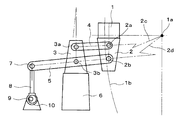
- FIG. 11 is a schematic diagram showing an eccentric cam type mold vibration device.
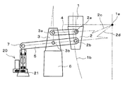
- the arm support portion 3 is installed on the partition wall 6.
- one end portion of the sub arm 4 and an intermediate portion of the main arm 5 are swingably supported by the horizontal rotation shafts 3a and 3b provided on the arm support portion 3, respectively.
- the mold 1 is supported on the vibration table 2 and vibrates together with the vibration table 2.
- the other end of the sub arm 4 and one end of the main arm 5 are swingably connected to the horizontal rotation axes a and 2b of the vibration table 2, respectively.
- the main arm 5 and the sub arm 4 constitute a parallel link, and the four points of the rotation shafts 3a, 3b, 2b, and 2a operate in association with each other with a constant distance between them.
- a motor 10 is installed with the rotating shaft horizontal, and an eccentric cam 9 is provided on the rotating shaft of the motor 10.
- the eccentric cam 9 and the rotary shaft 7 at the other end of the main arm 5 are connected by a link 8. Accordingly, when the motor 10 rotates, the eccentric cam 9 rotates, and the link 8 moves up and down via the eccentric cam 9.
- the link 8 moves up and down, the main arm 5 is swung, and the sub arm 4 is swung in conjunction. Thereby, the casting_mold
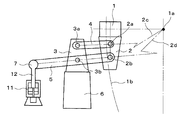
- FIG. 12 is a schematic diagram showing a hydraulic servo mold vibration device.
- a hydraulic servo cylinder 11 is installed instead of the eccentric cam.
- the upper end of the piston 12 is rotatably connected to the rotating shaft 7, and the other end portion (rotating shaft 7) of the main arm 5 is driven by the piston 12 driven by the hydraulic servo cylinder 11.
- FIG. 13 is a schematic diagram showing an electric servo type mold vibration device.
- an electric servo actuator 20 is installed instead of the eccentric cam shown in FIG.
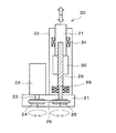
- FIG. 14 is a schematic diagram showing the electric servo actuator 20.
- a base 21 is installed on the equipment floor, and a servo motor 22 and a cylinder tube 33 are installed on the base 21.
- the servo motor 22 is arranged so that the rotating shaft 23 is positioned in the base 21 with its axial direction facing vertically downward, and a pulley 24 is attached to the rotating shaft 23.
- the screw shaft 29 of the ball screw is rotatably installed with an angular bearing 55 so that its axial direction is vertical, and a lower portion thereof is disposed in the base 21.
- a pulley 25 is attached to the lower end portion of the screw shaft 29, and a belt 26 is stretched between the pulley 24 and the pulley 25.
- a nut-side shaft 31 is fixed to the ball nut 30 coaxially with the screw shaft 29 on the upper portion of the screw shaft 29 arranged with the central axis vertical.
- the screw shaft 29 is screwed through a ball.
- the ball nut 30 moves up and down by forward and reverse rotation of the screw shaft 29.
- a nut side shaft 31 is fixed to the upper end of the ball nut 30 with its axial direction being vertical, and this nut side shaft 31 is supported by a ball spline 34 so as to be movable up and down.
- the upper end of the nut side shaft 31 protrudes upward from the upper portion of the cylinder tube 33, and the upper end of the nut side shaft 31 is connected to the rotary shaft 7 at the other end of the main arm 5.
- the amplitude of the vibration cannot be changed during the casting operation.
- the time pattern of mold vibration is limited to a sine wave only.
- the mold vibration is controlled by adjusting the control timing of the pressure on the side where the piston 12 of the hydraulic servo cylinder 11 is advanced and the pressure on the side where the piston 12 is retracted. The amplitude can be changed even during the casting operation.
- the pattern of the mold vibration is not limited to the sine wave vibration but can be set to a non-sinusoidal vibration.
- the electric servo mold vibration device can also change the amplitude of the mold vibration during the casting operation, and the pattern of the mold vibration can be set to either sine wave vibration or non-sinusoidal vibration. .
- the hydraulic servo type mold vibration device requires inspection of the filter and hydraulic fluid of the hydraulic servo cylinder 11, and the hydraulic hydraulic fluid requires contamination management.
- the servomotor is rotated forward and reverse to move the nut side shaft 31 up and down.
- the amplitude necessary for mold vibration is as small as about ⁇ 6 mm, for example, and therefore the amplitude at which the rotary shaft 7 of the main arm 5 moves up and down is accordingly small. Therefore, the rocking rotation angle of the screw shaft 29 is small, and continuous operation for a long time is required, and the screw shaft 29 and the ball nut 30 are required to be severely operated.
- the present invention has been made in view of such problems, and an object of the present invention is to provide a mold vibration device capable of extending its life in an electric servo mold vibration device that can be easily maintained. To do.
- the mold vibration device includes: In the mold vibration device that vibrates the mold of the continuous casting device, A servo motor, A ball screw unit including a ball screw having a screw shaft and a ball nut, and a nut side shaft fixedly provided on the ball nut coaxially with the screw shaft, the central axis extending in the vertical direction
- a second shaft that is the other of the screw shaft and the nut side shaft of the ball screw unit is configured to be coupled to the mold side;
- the mounting portion is provided so that relative movement in the vertical direction with respect to the bearing is impossible, and relative movement in
- the mounting portion includes a base portion that is detachably fixed to an installation target, The base is configured to be able to adjust the height of the bearing relative to the installation target when the mold vibration device stops operating by inserting a liner between the base and the installation target. May be.
- the mounting portion includes a base fixed to the installation target, and the base can adjust the height of the bearing relative to the installation target in a state where the mold vibration device stops operating.
- a height adjustment mechanism configured as described above may be provided.
- the height adjusting mechanism may be a hydraulic jack or a screw jack.
- the ball nut of the ball screw and the portion of the screw shaft of the ball screw engaged with the ball nut are immersed in lubricating oil so that the ball screw can be lubricated with an oil bath.
- a case surrounding at least a part of the ball screw A lubricating oil tank for storing lubricating oil;
- a recovery pipe connected to an outlet provided in a lower portion of the case and guiding lubricating oil to the lubricating oil tank;
- the bearing is fixed to the case;
- the attachment portion may be provided on the outer side surface of the case.
- a fulcrum is provided at an intermediate portion, one end is connected to the second shaft, and the other end is connected to the mold.
- the arm extends in the lateral direction, and the mold is moved up and down by swinging the arm. And an arm mechanism for applying vibration to the mold.
- the present invention it is possible to change the screwing position between the screw shaft and the ball nut constituting the ball screw that converts the forward / reverse rotational motion into the vertical motion. Since the screw shaft and the ball nut vibrate relatively repeatedly around this screwing position, the vicinity of the screwing position will be worn. By periodically changing the wear position, the mold The life of the actuator of the vibration device can be extended.
- FIG. 1 It is a schematic diagram which shows the electric actuator of the casting_mold
- FIG. 1 is a schematic diagram showing a concept of an electric actuator 120 of a mold vibration device according to a first embodiment of the present invention.
- the electric actuator 120 of the mold vibration device shown in FIG. 1 is further provided with a lubricating oil tank 41 below the base 21 in the electric actuator 20 shown in FIG. 14, and the lubricating oil in the lubricating oil tank 41 is used in the present invention.
- a pump 40 that circulates and supplies the cylinder tube 33 that functions as a case is installed.
- Lubricating oil pumped by the pump 40 is passed through a filter (not shown), supplied to the upper part of the cylinder tube 33 through the supply pipe 43, and tanked from the lower part of the cylinder tube 33 through the recovery pipe 42. It is collected by 41 and circulated and supplied to lubricate the screw shaft 29 and the ball nut 30.
- the screw shaft 29 and the ball nut 30 are immersed in this lubricating oil bath, the screw shaft 29 and the ball nut 30 are swung at a small rocking rotation angle and operated for a long time. Can be lubricated without causing oil film breakage.
- the supply device includes a supply pipe 43, a pump 40, and a filter (not shown).
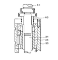
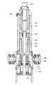
- FIG. 2 is a front sectional view showing the electric actuator 120, and FIGS. 3 and 4 are partially enlarged views thereof.
- FIG. 5 is a side sectional view of the same.
- a cylindrical cylinder tube 33 whose central axis is vertical is fixed upright.
- a bearing support portion 28 is provided at a lower portion of the cylinder tube 33, and an angular bearing 55 is fitted therein.
- the screw shaft 29 is rotatably supported by an angular bearing 55 with its central axis being vertical.
- the bearing 55 has an outer race 51 that supports the ball 50 from an outer side and an inner race 52 that contacts the outer peripheral surface of the screw shaft 29 and supports the ball 50 from the inner side, and is fixed between the inner race 52 and the outer race 51.
- the balls 50 are stored so as not to be detached.
- the screw shaft 29 is supported so as to rotate about the central axis.
- the ball screw of the present invention only needs to be arranged so that the central axis extends in the vertical direction, and can be arranged obliquely, but the central axis of the ball screw is vertical as in this embodiment. By arrange
- a ball nut 30 is disposed inside the cylinder tube 33, and the ball nut 30 is screwed onto the screw shaft 29 via a ball.
- a nut side shaft 31 that is fixed to the ball nut 30 coaxially with the screw shaft 29 is disposed inside the cylinder tube 33.
- the screw shaft 29 functions as the first shaft of the present invention
- the nut side shaft 31 functions as the second shaft.
- a ball spline 34 is fixed to the cylinder tube 33 on the inner surface of the cylinder tube 33 at a position aligned with the nut side shaft 31.
- the nut side shaft 31 is supported by a ball spline 34 so as to be able to reciprocate in the vertical direction and not to rotate. Since the nut side shaft 31 is supported by the ball spline 34 so as not to rotate, the nut side shaft 31 cannot rotate around the central axis. Accordingly, when the screw shaft 29 is reciprocally rotated (oscillated) around the axis center, the ball nut 30 screwed into the screw shaft 29 via the ball is moved in the vertical direction at a distance corresponding to the oscillation rotation angle. Move back and forth.
- a cylindrical stopper 63 is disposed so as to surround the screw shaft 29.
- the upper end of the nut side shaft 31 protrudes upward from the upper part of the cylinder tube 33, and the upper end of the nut side shaft 31 is connected to the mold vibration device and the mold side of the mold.
- a connecting portion 61 is provided at the upper end of the nut side shaft 31, and this connecting portion 61 is rotatably connected to the rotating shaft 7 of the main arm 5. Therefore, when the nut side shaft 31 moves up and down, the main arm 5 swings and the mold can be vibrated.
- the mold vibration device is directly connected to the mold trunnion, the upper end of the nut side shaft is directly connected to the mold trunnion. Since the mold and the mold vibration device can be installed in separate sections with the partition wall 6 therebetween, the mold vibration device can be avoided from being installed in a high temperature environment around the mold.
- a motor 22 is installed on the base 21 in parallel with the cylinder tube 33, and a rotating shaft 23 of the motor 22 is inserted into the base 21 with its center of rotation as the vertical direction.
- a pulley 24 is attached to the rotating shaft 23, and a pulley 25 is attached to a portion of the screw shaft 29 inserted into the base 21.
- a belt 26 is stretched between the pulleys 24 and 25, so that when the rotating shaft 23 of the motor 22 rotates and rotates, the rotating rotation is transmitted to the screw shaft 29 via the belt 26. Is done. Accordingly, in the present embodiment, the pulleys 24 and 25 and the belt 26 function as a power transmission mechanism.
- FIG. 8 is a schematic side view of the electric actuator according to the first embodiment.
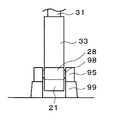
- a trunnion 98 is fixed to the outer surface of the bearing support portion 28, and is detachably fixed to a pedestal 99 to be installed via a trunnion bearing 95 by a fixing means such as a screw. Therefore, the trunnion 98 and the trunnion bearing 95 function as a mounting portion of the present invention, and among these, the trunnion bearing 95 functions as a base portion of the present invention.
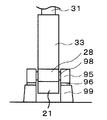
- FIG. 9 is a schematic side view of the electric actuator of the first embodiment, and shows a state in which a liner 96 is inserted below the trunnion bearing 95 of FIG. Since the trunnion bearing 95 is detachably fixed to the pedestal 99 and the liner 96 can be inserted between the trunnion bearing 95 and the pedestal 99, the mold vibration device has stopped operating. It is possible to adjust the height of the bearing 55 with respect to the pedestal 99 in the state.
- the second shaft in this embodiment, the nut side shaft 31
- the nut side shaft 31 is fixed in a state where the operation of the mold vibration device is stopped, changing the height of the bearing 55 relative to the pedestal 99, The relative position in the vertical direction with respect to the nut side shaft 31 (second shaft) will be changed.
- one liner 96 is inserted in FIG. 9, the height can be adjusted step by step by inserting a plurality of liners of the same thickness or by inserting liners of different thicknesses. is there.
- the trunnion bearing 95 is provided so as to be unable to move in the vertical direction relative to the bearing 55, and the bearing 55 and the nut in a state in which the mold vibration device has stopped operating.
- the vertical position relative to the side shaft 31 can be changed. Therefore, the screwing position between the screw shaft 29 and the ball nut 30 in a state where the operation of the mold vibration device is stopped can be changed. Since the screw shaft 29 and the ball nut 30 vibrate relatively repeatedly with the screwing position as the center, the vicinity of the screwing position is worn out. By periodically changing the worn position, The life of the actuator of the mold vibration device can be extended.
- a lubricating oil tank 41 is installed below the base 21, and the lubricating oil in the lubricating oil tank 41 is transferred to the cylinder by a small pump 40 installed on the lubricating oil tank 41. It is supplied to an inflow port 90 (see FIG. 5) provided in the upper part of the tube 33 via a supply pipe 43 (see FIG. 1). The lubricating oil supplied into the cylinder tube 33 is collected in the lubricating oil tank 41 from the outlet 91 provided at the lower portion of the cylinder tube 33 via the collecting pipe 42 (see FIGS. 1 and 2).
- the position where the inflow port is provided is not particularly limited as long as it is above the outflow port.
- a ball spline or the like can be moved up and down and cannot rotate.
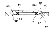
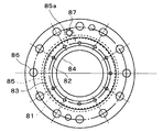
- a bearing retainer 80 is fixed to the lower surface of the angular bearing 55.
- FIG. 6 is a front sectional view of the bearing retainer 80
- FIG. 7 is a bottom view of the bearing retainer 80.
- the bearing retainer 80 has an annular shape, and has a three-stage configuration including an inner edge 84 having the smallest diameter on the upper surface, a lower middle edge 82, and a lower lower edge 83.
- An upper edge 85 smaller than the entire outer edge is formed as a step on the upper surface of the bearing retainer 80, and a groove 81 is formed on the radially inner side of the upper edge 85 with the upper surface slightly lowered. .
- the upper edge 85 has the same diameter as the outer edge of the bearing 55, the upper edge 85 is brought into contact with the bearing 55, and the presser 80 is fixed to the lower surface of the bearing support portion 28 by screws.
- a seal 74 is fitted into the middle edge 82 of the presser 80.
- a metal ring 73 is fitted between the seal 74 and the screw shaft 29 so as to be fitted to the screw shaft 29. Further, the metal ring 73 is fixed by a cylindrical fixing member 76 which is externally fitted to the screw shaft 29 and is fixed by being externally fitted to the screw shaft 29, and between the metal ring 73 and the fixing member 76.
- An umbrella-shaped member having a horizontal ring-like portion is sandwiched between the upper ends of the cone-shaped member 71 and a rotating umbrella portion 71 is formed. Further, the seal 74 is fixed to the presser 80 so as not to be detached from the presser 80 by fixing an annular presser plate 75 to the lower surface of the presser 80 by screwing.
- an oval counterbore portion 85a is formed in a region extending from the groove 81 to the outer side of the upper edge 85 in the radial direction.
- a radial direction is formed.
- a channel 87 that penetrates the presser 80 in the thickness direction is formed in the outer portion.
- the lubricating oil flows out from the outlet 90 through the flow path 87 in the presser 80 and is guided to the lubricating oil tank 41 by the recovery pipe 42.
- the cylinder tube 33, the bearing support portion 28, and the bearing retainer 80 function as the case of the present invention.
- the rotating umbrella portion 71 has a conical shape extending downward, and an umbrella-shaped member having a horizontal ring-shaped portion at the upper end thereof is externally fitted to the screw shaft 29. And an umbrella-shaped member is fixed to the screw shaft 29.
- the fixed umbrella portion 72 has an umbrella shape having a conical portion 72b that extends downward at the same angle as the conical portion of the rotating umbrella portion 71, and a horizontal portion 72a that extends horizontally outward from the lower end of the conical portion 72b. This is formed by fixing the horizontal portion 72 a of the member to the upper surface of the base 21.
- a hole 70 through which the screw shaft 29 is inserted is formed in the upper wall of the base 21, and the horizontal portion 72 a of the umbrella-shaped member forming the fixed umbrella portion 72 is fixed to the peripheral portion of the hole 70.
- the rotating umbrella portion 71 that rotates together with the screw shaft 29 and the fixed umbrella portion 72 that is fixed to the base 21 have the rotating umbrella portion 71 facing upward, and at least a portion of the conical portion in the radial direction is the entire circumference. It is arranged overlapping.
- the bearing support portion 28 is provided with a discharge port 93 for discharging the lubricating oil received on the fixed umbrella portion 72 to the outside.
- the cone portion of the fixed umbrella portion 72 flows from the conical portion of the rotary umbrella portion 71 and is fixed. It is guided onto the horizontal part 72 a of the umbrella part 72 and discharged from the discharge port 93 to the outside. Therefore, even when the lubricating oil leaks downward from the inner edge of the presser 80 in this manner, the lubricating oil does not leak down to the lower portion of the fixed umbrella portion 72 and reach the pulley 25 or the belt 26.
- the lubricating oil discharged to the outside from the discharge port 93 is discarded outside without being collected in the lubricating oil tank.
- the screw shaft 29 and the ball nut 30 operate in a state of being immersed in the lubricating oil, the wear is remarkably reduced. Thereby, the lifetime of the actuator of the mold vibration device can be extended. Further, by providing the rotating umbrella portion 71 and the fixed umbrella portion 72, the lubricating oil is more reliably sealed to prevent entry into the base 21 and adhere to the pulleys 24, 25 and the belt 26 in the base 21. Thus, it is possible to prevent the operation from being hindered and the belt from being deteriorated.
- FIG. 10 is a schematic side view of the electric actuator according to the second embodiment.
- the point that the trunnion 98 is fixed to the outer surface of the bearing support portion 28 is the same as that of the first embodiment.
- the trunnion 98 and the trunnion bearing 95 that function as the mounting portion of the present invention are disposed below.
- a screw-type jack device 97 that functions as a base is provided, and the screw-type jack device 97 is fixed to the base 99.
- the screw type jack device 97 by changing the height of the trunnion 98 with the screw type jack device 97, it is possible to adjust the height of the bearing 55 with respect to the pedestal 99 when the mold vibration device stops operating. Since the second shaft (in this embodiment, the nut side shaft 31) is fixed in a state where the operation of the mold vibration device is stopped, changing the height of the bearing 55 relative to the pedestal 99, The relative position in the vertical direction with respect to the nut side shaft 31 (second shaft) will be changed.
- the screw type jack device is provided as the base portion is shown, but the height adjusting mechanism of the present invention is not limited to this, and a hydraulic jack device may be used, or the height is adjusted. There is no particular limitation as long as the mechanism can be used.
- the screw-type jack device 97 is provided so as not to be able to move in the vertical direction with respect to the bearing 55, and the bearing 55 in a state where the mold vibration device has stopped operating.
- the nut-side shaft 31 are configured so that the relative position in the vertical direction can be changed. Therefore, the screwing position between the screw shaft 29 and the ball nut 30 in a state where the mold vibration device stops operating can be changed, and the same effect as the first embodiment can be obtained, and the life of the actuator of the mold vibration device can be obtained. Can be prolonged.
- the trunnion 98 functioning as the mounting portion is provided on the outer surface of the bearing support portion 28, but it is only necessary that the trunnion 98 be provided so as not to be movable relative to the bearing in the vertical direction. Therefore, the same effect is acquired because the bearing is fixed to the case and the mounting portion is provided on the outer side surface of the case. Therefore, when the bearing is fixed to the bearing support portion 28 that functions as a part of the case as described above, the side surface of the cylinder tube 33 that is integrated with the bearing support portion 28 and functions as a part of the case. A trunnion 98 may be provided.
- positioned below is a structure which is a screw axis
- the nut side shaft may be arranged on the lower side to serve as the first shaft. That is, the ball screw unit may be installed upside down in the case of the above embodiment.
- the outlet of the present invention is provided below the bearing in the lower part of the case.
- the upper end or the lower end of the bearing is sealed in a liquid-tight manner, It is also possible to provide an outlet on the upper side of the bearing.
- a foreign substance is formed in the bearing by providing an outlet on the lower side of the bearing and allowing the lubricating oil to flow out and collected through the gap between the inner race and the outer race of the bearing. Can be prevented from accumulating.
Landscapes
- Engineering & Computer Science (AREA)
- General Engineering & Computer Science (AREA)
- Mechanical Engineering (AREA)
- Power Engineering (AREA)
- Microelectronics & Electronic Packaging (AREA)
- Transmission Devices (AREA)
- Continuous Casting (AREA)
Abstract
Description
連続鋳造装置の鋳型を振動させる鋳型振動装置において、
サーボモータと、
ねじ軸及びボールナットを有するボールねじと、前記ねじ軸と同軸的に前記ボールナットに固定的に設けられたナット側軸とを含み、中心軸が上下方向に延びるように配置されたボールねじユニットと、
前記ボールねじユニットの前記ねじ軸と前記ナット側軸とのうちの一方であって下側に配置された方である第1軸に前記サーボモータの回転軸から回転運動を伝達する動力伝達機構と、
前記第1軸と係合して前記第1軸を回転可能に支持するとともに、前記第1軸に対して上下方向の相対移動がなされないよう設けられた軸受と、
前記鋳型振動装置を設置位置に固定するための取付部と、
を備え、
前記ボールねじユニットの前記ねじ軸と前記ナット側軸とのうちの他方である第2軸が前記鋳型側に連結されるよう構成されており、
前記取付部は、前記軸受に対する上下方向の相対移動が不可能となるように設けられているとともに、前記鋳型振動装置が動作を停止した状態における前記軸受と前記第2軸との上下方向の相対位置を変更可能に構成されていることを特徴とする。
前記取付部は、設置対象に対して着脱可能に固定される基部を備え、
前記基部は、前記設置対象との間にライナーを挿入することにより、前記鋳型振動装置が動作を停止した状態における前記設置対象に対する前記軸受の高さを調節することが可能なように構成されていてもよい。
或いは、前記取付部が、設置対象に対して固定される基部を備え、前記基部は、前記鋳型振動装置が動作を停止した状態における前記設置対象に対する前記軸受の高さを調節することが可能なように構成された高さ調節機構を備えていてもよい。そして、前記高さ調節機構は、油圧ジャッキ又はねじ式ジャッキであってもよい。
前記ボールねじの前記ボールナットと、前記ボールねじの前記ねじ軸のうち前記ボールナットが係合している部分とを潤滑油に浸して前記ボールねじを油浴により潤滑可能とするよう構成された、前記ボールねじの少なくとも一部を囲うケースと、
潤滑油を貯留する潤滑油タンクと、
前記ケースの下部に設けられた流出口に接続され、潤滑油を前記潤滑油タンクに導く回収管と、
前記潤滑油タンク内の潤滑油を前記ケースの前記流出口よりも上方に設けられた流入口から前記ケース内に再び供給する供給装置と、
を有するように構成することができる。
前記軸受が前記ケースに固定されており、
前記取付部が、前記ケースの外側側面上に設けられていてもよい。
中間部に支点が設けられ、一端が前記第2軸に連結されると共に他端が前記鋳型に連結された、横方向に延びるアームを有し、前記アームの揺動により前記鋳型を上下動させて前記鋳型に振動を付与するアーム機構をさらに備えていてもよい。
7:回転軸
21:ベース
22:モータ
23:回転軸
24,25:プーリ
26:ベルト
27:駆動軸
28:軸受支持部
29:ねじ軸
30:ボールナット
31:ナット側軸
32:ボールねじ
33:シリンダチューブ
34:ボールスプライン
40:ポンプ
41:潤滑油タンク
42:回収管
43:供給管
50:ボール
51:外側レース
52:内側レース
55:アンギュラ軸受
87:流路
90:流入口
91:流出口
93:排出口
95:トラニオン軸受
96:ライナー
97:ジャッキ装置
98:トラニオン
99:台座
120:電動アクチュエータ
Claims (7)
- 連続鋳造装置の鋳型を振動させる鋳型振動装置において、
サーボモータと、
ねじ軸及びボールナットを有するボールねじと、前記ねじ軸と同軸的に前記ボールナットに固定的に設けられたナット側軸とを含み、中心軸が上下方向に延びるように配置されたボールねじユニットと、
前記ボールねじユニットの前記ねじ軸と前記ナット側軸とのうちの一方であって下側に配置された方である第1軸に前記サーボモータの回転軸から回転運動を伝達する動力伝達機構と、
前記第1軸と係合して前記第1軸を回転可能に支持するとともに、前記第1軸に対する上下方向の相対移動がなされないよう設けられた軸受と、
前記鋳型振動装置を設置位置に固定するための取付部と、
を備え、
前記ボールねじユニットの前記ねじ軸と前記ナット側軸とのうちの他方である第2軸が前記鋳型側に連結されるよう構成されており、
前記取付部は、前記軸受に対する上下方向の相対移動が不可能となるように設けられているとともに、前記鋳型振動装置が動作を停止した状態における前記軸受と前記第2軸との上下方向の相対位置を変更可能に構成されていることを特徴とする鋳型振動装置。 - 前記取付部は、設置対象に対して着脱可能に固定される基部を備え、
前記基部は、前記設置対象との間にライナーを挿入することにより、前記鋳型振動装置が動作を停止した状態における前記設置対象に対する前記軸受の高さを調節することが可能なように構成されていることを特徴とする請求項1に記載の鋳型振動装置。 - 前記取付部は、設置対象に対して固定される基部を備え、
前記基部は、前記鋳型振動装置が動作を停止した状態における前記設置対象に対する前記軸受の高さを調節することが可能なように構成された高さ調節機構を備えていることを特徴とする請求項1に記載の鋳型振動装置。 - 前記高さ調節機構が、油圧ジャッキ又はねじ式ジャッキであることを特徴とする請求項3に記載の鋳型振動装置。
- 前記ボールねじの前記ボールナットと、前記ボールねじの前記ねじ軸のうち前記ボールナットが係合している部分とを潤滑油に浸して前記ボールねじを油浴により潤滑可能とするよう構成された、前記ボールねじの少なくとも一部を囲うケースと、
潤滑油を貯留する潤滑油タンクと、
前記ケースの下部に設けられた流出口に接続され、潤滑油を前記潤滑油タンクに導く回収管と、
前記潤滑油タンク内の潤滑油を前記ケースの前記流出口よりも上方に設けられた流入口から前記ケース内に再び供給する供給装置と、
を有することを特徴とする請求項1乃至4のいずれか1項に記載の鋳型振動装置。 - 前記軸受が前記ケースに固定されており、
前記取付部が、前記ケースの外側側面上に設けられていることを特徴とする、請求項5に記載の鋳型振動装置。 - 中間部に支点が設けられ、一端が前記第2軸に連結されると共に他端が前記鋳型に連結された、横方向に延びるアームを有し、前記アームの揺動により前記鋳型を上下動させて前記鋳型に振動を付与するアーム機構をさらに備えることを特徴とする請求項1乃至6のいずれか1項に記載の鋳型振動装置。
Priority Applications (3)
| Application Number | Priority Date | Filing Date | Title |
|---|---|---|---|
| US15/552,128 US10232432B2 (en) | 2015-02-19 | 2016-02-09 | Mold oscillator |
| EP16752355.4A EP3260220B1 (en) | 2015-02-19 | 2016-02-09 | Mold vibrating device |
| KR1020177022764A KR101941396B1 (ko) | 2015-02-19 | 2016-02-09 | 주형 진동 장치 |
Applications Claiming Priority (2)
| Application Number | Priority Date | Filing Date | Title |
|---|---|---|---|
| JP2015030295A JP6522363B2 (ja) | 2015-02-19 | 2015-02-19 | 鋳型振動装置 |
| JP2015-030295 | 2015-02-19 |
Publications (1)
| Publication Number | Publication Date |
|---|---|
| WO2016132969A1 true WO2016132969A1 (ja) | 2016-08-25 |
Family
ID=56689200
Family Applications (1)
| Application Number | Title | Priority Date | Filing Date |
|---|---|---|---|
| PCT/JP2016/053815 Ceased WO2016132969A1 (ja) | 2015-02-19 | 2016-02-09 | 鋳型振動装置 |
Country Status (5)
| Country | Link |
|---|---|
| US (1) | US10232432B2 (ja) |
| EP (1) | EP3260220B1 (ja) |
| JP (1) | JP6522363B2 (ja) |
| KR (1) | KR101941396B1 (ja) |
| WO (1) | WO2016132969A1 (ja) |
Families Citing this family (3)
| Publication number | Priority date | Publication date | Assignee | Title |
|---|---|---|---|---|
| JP6514809B1 (ja) * | 2018-05-22 | 2019-05-15 | 豐田 陳 | ローリングボールボルトキット及びその使用方法 |
| JP2020092733A (ja) * | 2018-12-10 | 2020-06-18 | 株式会社笹原商事 | 油供給機 |
| CN116494121A (zh) * | 2023-02-16 | 2023-07-28 | 浙江谋皮环保科技有限公司 | 刷辊对刷用升降机构及可升降式刷辊支撑座 |
Citations (3)
| Publication number | Priority date | Publication date | Assignee | Title |
|---|---|---|---|---|
| JPS63256242A (ja) * | 1987-04-15 | 1988-10-24 | Sumitomo Heavy Ind Ltd | モ−ルドオシレ−シヨン装置の駆動方式 |
| JPH09295105A (ja) * | 1996-05-02 | 1997-11-18 | Nippon Steel Corp | 連続鋳造中の鋳型振動方法 |
| JP2003220638A (ja) * | 2002-01-29 | 2003-08-05 | Sumitomo Heavy Ind Ltd | 射出成形機の潤滑装置 |
Family Cites Families (8)
| Publication number | Priority date | Publication date | Assignee | Title |
|---|---|---|---|---|
| US4727924A (en) * | 1986-10-08 | 1988-03-01 | Georgetown Steel Corporation | Mold oscillator |
| US4945975A (en) * | 1988-12-08 | 1990-08-07 | Kawasaki Steel Corporation | Method of oscillation of mold of vertical continuous caster |
| JP2795602B2 (ja) * | 1993-10-21 | 1998-09-10 | 日立造船株式会社 | 連続鋳造設備におけるモールド振動装置 |
| TW274529B (ja) * | 1993-10-21 | 1996-04-21 | Hitachi Shipbuilding Eng Co | |
| DE19515316C1 (de) | 1995-04-19 | 1996-08-29 | Mannesmann Ag | Verfahren zum Betreiben einer Kokille |
| US5983743A (en) * | 1997-04-03 | 1999-11-16 | Dresser Industries, Inc. | Actuator assembly |
| JP3026173B2 (ja) * | 1997-04-22 | 2000-03-27 | 住友重機械工業株式会社 | モールドオシレーション駆動制御装置 |
| CN101594972B (zh) * | 2007-07-19 | 2013-03-06 | 株式会社沙迪克 | 注射成型机的合模装置 |
-
2015
- 2015-02-19 JP JP2015030295A patent/JP6522363B2/ja active Active
-
2016
- 2016-02-09 US US15/552,128 patent/US10232432B2/en active Active
- 2016-02-09 WO PCT/JP2016/053815 patent/WO2016132969A1/ja not_active Ceased
- 2016-02-09 KR KR1020177022764A patent/KR101941396B1/ko active Active
- 2016-02-09 EP EP16752355.4A patent/EP3260220B1/en active Active
Patent Citations (3)
| Publication number | Priority date | Publication date | Assignee | Title |
|---|---|---|---|---|
| JPS63256242A (ja) * | 1987-04-15 | 1988-10-24 | Sumitomo Heavy Ind Ltd | モ−ルドオシレ−シヨン装置の駆動方式 |
| JPH09295105A (ja) * | 1996-05-02 | 1997-11-18 | Nippon Steel Corp | 連続鋳造中の鋳型振動方法 |
| JP2003220638A (ja) * | 2002-01-29 | 2003-08-05 | Sumitomo Heavy Ind Ltd | 射出成形機の潤滑装置 |
Also Published As
| Publication number | Publication date |
|---|---|
| EP3260220A1 (en) | 2017-12-27 |
| KR20170107004A (ko) | 2017-09-22 |
| EP3260220B1 (en) | 2020-12-30 |
| US20180043424A1 (en) | 2018-02-15 |
| JP2016150373A (ja) | 2016-08-22 |
| US10232432B2 (en) | 2019-03-19 |
| JP6522363B2 (ja) | 2019-05-29 |
| KR101941396B1 (ko) | 2019-01-22 |
| EP3260220A4 (en) | 2018-02-28 |
Similar Documents
| Publication | Publication Date | Title |
|---|---|---|
| CN103476502B (zh) | 圆锥形破碎机 | |
| WO2016132969A1 (ja) | 鋳型振動装置 | |
| US20160030953A1 (en) | Centrifuge having a lubricant system | |
| US10047734B2 (en) | Hydrostatic axial piston machine | |
| US5934583A (en) | Bearing block mounting arrangement of a cone crusher | |
| JP6103458B2 (ja) | コーン型クラッシャー | |
| JP5446314B2 (ja) | 平面研削盤の反転テーブル装置 | |
| JP6522362B2 (ja) | 鋳型振動装置 | |
| US20160250733A1 (en) | Machining Apparatus | |
| CN111872341A (zh) | 一种具有消泡功能的液压铸造设备 | |
| JP2022066848A (ja) | 工作機械の主軸装置のドレン構造 | |
| CN107831033A (zh) | 便携式金属取样机及取样方法 | |
| JP2011179548A (ja) | ティルティングパッド軸受装置 | |
| JP2016150373A5 (ja) | ||
| CN209632746U (zh) | 一种航空用轴承套圈外圈磨床 | |
| CN118237722B (zh) | 一种搅拌摩擦增材制造装置 | |
| JP2000158313A (ja) | レンズ加工方法および装置 | |
| CN223498743U (zh) | 转子阀和高温高压设备 | |
| JP5332710B2 (ja) | 平面研削盤の反転テーブル装置 | |
| JP7410497B2 (ja) | 追従型検査装置、及び、追従型検査方法 | |
| CN210037080U (zh) | 一种加速度差振动装置 | |
| JP2018141462A (ja) | ポンプ装置およびポンプ装置のメンテナンス方法 | |
| USRE24754E (en) | becker r | |
| CN121876644A (zh) | 一种流体状化工原料快速冷却装置 | |
| JP2010194694A (ja) | 平面研削盤の反転テーブル案内装置 |
Legal Events
| Date | Code | Title | Description |
|---|---|---|---|
| REEP | Request for entry into the european phase |
Ref document number: 2016752355 Country of ref document: EP |
|
| 121 | Ep: the epo has been informed by wipo that ep was designated in this application |
Ref document number: 16752355 Country of ref document: EP Kind code of ref document: A1 |
|
| ENP | Entry into the national phase |
Ref document number: 20177022764 Country of ref document: KR Kind code of ref document: A |
|
| WWE | Wipo information: entry into national phase |
Ref document number: 15552128 Country of ref document: US |
|
| NENP | Non-entry into the national phase |
Ref country code: DE |