WO2016133003A1 - ハイブリッド太陽電池モジュール - Google Patents
ハイブリッド太陽電池モジュール Download PDFInfo
- Publication number
- WO2016133003A1 WO2016133003A1 PCT/JP2016/054039 JP2016054039W WO2016133003A1 WO 2016133003 A1 WO2016133003 A1 WO 2016133003A1 JP 2016054039 W JP2016054039 W JP 2016054039W WO 2016133003 A1 WO2016133003 A1 WO 2016133003A1
- Authority
- WO
- WIPO (PCT)
- Prior art keywords
- solar cell
- cell module
- hybrid solar
- resin
- hybrid
- Prior art date
- Legal status (The legal status is an assumption and is not a legal conclusion. Google has not performed a legal analysis and makes no representation as to the accuracy of the status listed.)
- Ceased
Links
Images


Classifications
-
- F—MECHANICAL ENGINEERING; LIGHTING; HEATING; WEAPONS; BLASTING
- F24—HEATING; RANGES; VENTILATING
- F24S—SOLAR HEAT COLLECTORS; SOLAR HEAT SYSTEMS
- F24S20/00—Solar heat collectors specially adapted for particular uses or environments
-
- H—ELECTRICITY
- H02—GENERATION; CONVERSION OR DISTRIBUTION OF ELECTRIC POWER
- H02S—GENERATION OF ELECTRIC POWER BY CONVERSION OF INFRARED RADIATION, VISIBLE LIGHT OR ULTRAVIOLET LIGHT, e.g. USING PHOTOVOLTAIC [PV] MODULES
- H02S40/00—Components or accessories in combination with PV modules, not provided for in groups H02S10/00 - H02S30/00
- H02S40/40—Thermal components
- H02S40/44—Means to utilise heat energy, e.g. hybrid systems producing warm water and electricity at the same time
-
- H—ELECTRICITY
- H10—SEMICONDUCTOR DEVICES; ELECTRIC SOLID-STATE DEVICES NOT OTHERWISE PROVIDED FOR
- H10F—INORGANIC SEMICONDUCTOR DEVICES SENSITIVE TO INFRARED RADIATION, LIGHT, ELECTROMAGNETIC RADIATION OF SHORTER WAVELENGTH OR CORPUSCULAR RADIATION
- H10F19/00—Integrated devices, or assemblies of multiple devices, comprising at least one photovoltaic cell covered by group H10F10/00, e.g. photovoltaic modules
- H10F19/80—Encapsulations or containers for integrated devices, or assemblies of multiple devices, having photovoltaic cells
-
- H—ELECTRICITY
- H10—SEMICONDUCTOR DEVICES; ELECTRIC SOLID-STATE DEVICES NOT OTHERWISE PROVIDED FOR
- H10F—INORGANIC SEMICONDUCTOR DEVICES SENSITIVE TO INFRARED RADIATION, LIGHT, ELECTROMAGNETIC RADIATION OF SHORTER WAVELENGTH OR CORPUSCULAR RADIATION
- H10F19/00—Integrated devices, or assemblies of multiple devices, comprising at least one photovoltaic cell covered by group H10F10/00, e.g. photovoltaic modules
- H10F19/80—Encapsulations or containers for integrated devices, or assemblies of multiple devices, having photovoltaic cells
- H10F19/85—Protective back sheets
-
- Y—GENERAL TAGGING OF NEW TECHNOLOGICAL DEVELOPMENTS; GENERAL TAGGING OF CROSS-SECTIONAL TECHNOLOGIES SPANNING OVER SEVERAL SECTIONS OF THE IPC; TECHNICAL SUBJECTS COVERED BY FORMER USPC CROSS-REFERENCE ART COLLECTIONS [XRACs] AND DIGESTS
- Y02—TECHNOLOGIES OR APPLICATIONS FOR MITIGATION OR ADAPTATION AGAINST CLIMATE CHANGE
- Y02E—REDUCTION OF GREENHOUSE GAS [GHG] EMISSIONS, RELATED TO ENERGY GENERATION, TRANSMISSION OR DISTRIBUTION
- Y02E10/00—Energy generation through renewable energy sources
- Y02E10/40—Solar thermal energy, e.g. solar towers
-
- Y—GENERAL TAGGING OF NEW TECHNOLOGICAL DEVELOPMENTS; GENERAL TAGGING OF CROSS-SECTIONAL TECHNOLOGIES SPANNING OVER SEVERAL SECTIONS OF THE IPC; TECHNICAL SUBJECTS COVERED BY FORMER USPC CROSS-REFERENCE ART COLLECTIONS [XRACs] AND DIGESTS
- Y02—TECHNOLOGIES OR APPLICATIONS FOR MITIGATION OR ADAPTATION AGAINST CLIMATE CHANGE
- Y02E—REDUCTION OF GREENHOUSE GAS [GHG] EMISSIONS, RELATED TO ENERGY GENERATION, TRANSMISSION OR DISTRIBUTION
- Y02E10/00—Energy generation through renewable energy sources
- Y02E10/50—Photovoltaic [PV] energy
-
- Y—GENERAL TAGGING OF NEW TECHNOLOGICAL DEVELOPMENTS; GENERAL TAGGING OF CROSS-SECTIONAL TECHNOLOGIES SPANNING OVER SEVERAL SECTIONS OF THE IPC; TECHNICAL SUBJECTS COVERED BY FORMER USPC CROSS-REFERENCE ART COLLECTIONS [XRACs] AND DIGESTS
- Y02—TECHNOLOGIES OR APPLICATIONS FOR MITIGATION OR ADAPTATION AGAINST CLIMATE CHANGE
- Y02E—REDUCTION OF GREENHOUSE GAS [GHG] EMISSIONS, RELATED TO ENERGY GENERATION, TRANSMISSION OR DISTRIBUTION
- Y02E10/00—Energy generation through renewable energy sources
- Y02E10/60—Thermal-PV hybrids
Definitions
- the present invention relates to a hybrid solar cell module that simultaneously realizes power generation using sunlight and hot water supply using solar heat.
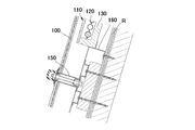
- FIG. 5 is an attachment cross-sectional view of the conventional solar system disclosed in Patent Document 1.
- the solar system described in Patent Document 1 a part of the solar panels 100 arranged on the roof R or the like is selected, and the heat collecting tube 120 and the heat insulating material 130 are provided only on the lower side thereof.
- the solar hot water panel 110 is installed, and the solar hot water panel 110 can be laid out at an optimal position.
- the frame 150 of the existing solar panel 100 cannot be used as it is. That is, since the pedestal 160 of the solar hot water panel 110 is separately provided, the panel installation work is complicated.
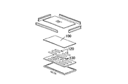
- FIG. 6 is an assembly diagram of the integrally formed solar thermoelectric hot water panel shown in Patent Document 2.
- the solar panel 100, the heat collecting tube 120, and the heat insulating material 130 have an integrated structure, so that a panel having two functions can be installed in a conventional frame. Has an effect.
- JP 2013-2709 A Japanese Patent Laid-Open No. 2000-241030
- the solar panel and the resin pipe through which the liquid passes are integrally coupled, and it is lightweight and inexpensive, can withstand long-term use, and throughout the year. It aims at providing the hybrid solar cell module which can supply warm water.
- a hybrid solar cell module is a solar panel provided on the sunlight receiving surface side, a resin pipe through which liquid passes, a rubber material, and a back surface provided on the back surface side. Glass, and the resin pipe is surrounded by the rubber material while being in contact with the back surface of the solar panel and the back glass, and uses solar power to generate electricity. The temperature rise of the liquid passing through the resin pipe is realized at the same time.
- the hybrid solar cell module of the first invention power generation using sunlight and supply of a liquid whose temperature has increased using solar heat are realized simultaneously using a frame or the like used in a conventional solar cell module. There is an effect that can be.
- the hybrid solar cell module of the first invention is provided with a rubber material layer at the bottom of the solar cell panel, and a resin pipe is provided therein, and a liquid such as water is circulated through the resin pipe, While generating electricity with sunlight, it produces hot water etc. with solar heat. Hot water or the like circulates through resin pipes, so there is no corrosion at all compared to the case of using conventional metal pipes.
- the resin pipe is covered with a rubber material layer and has excellent heat collection, thermal conductivity, and heat retention, and efficiently produces hot water by solar heat. can do.
- the hybrid solar cell module of the second invention has the following features in the first invention.
- a plurality of or meandering resin pipes are provided for one hybrid solar cell module, and between the adjacent resin pipes, the back surface of the solar panel, the rubber material, and the back glass
- An enclosed air layer is provided.
- an air layer is provided inside the rubber material layer surrounding the resin pipe through which hot water or the like circulates, so that not only the heat insulation effect is improved, but also the amount of the rubber material Therefore, it can contribute to further cost reduction and weight reduction.
- the hybrid solar cell module of the third invention has the following features in the first invention.
- the solar panel is obtained by laminating a surface glass, a sealing material containing solar cells, and a cell crack prevention sheet.
- a cell crack prevention sheet is inserted between the solar cell panel and the rubber material layer. Therefore, when the hybrid solar battery module of the third invention is manufactured, it is manufactured by laminating by vacuum pressurization, and at this time, cell cracking of the solar battery panel can be prevented.
- the sheet has a cushioning property, and even if an impact force or pressing force is applied, it is possible to prevent cracking of the solar battery cells of the solar battery panel.
- the hybrid solar cell module of the fourth invention has the following features in the first invention or the second invention.
- the resin pipe is made of a crosslinked polyethylene resin or a polybutene resin.
- the resin pipe through which hot water circulates is made of a cross-linked polyethylene resin or polybutene resin.
- a hybrid solar cell module in which no leakage occurs can be realized.
- a core such as a Teflon (registered trademark) resin rod for preventing the resin pipe from being crushed becomes unnecessary.
- the hybrid solar cell module of the fifth invention has the following features in the first invention or the second invention.
- the water pressure resistance in the resin pipe is 0.2 ° C. or higher at 25 ° C.
- the hybrid solar cell module of the sixth invention has the following features in the first invention or the second invention.
- the total volume of the resin pipe is 100 cc to 8000 cc with respect to one hybrid solar cell module.
- required hot water or the like can be obtained by the hybrid solar cell module of the present invention.
- the hybrid solar cell module of the seventh invention has the following features in the second invention.
- the air layer is provided at three or more locations for one hybrid solar cell module.
- the same effect as in the second aspect can be exhibited.
- the hybrid solar cell module of the eighth invention has the following characteristics in the third invention.
- the sealing material is an olefin-based sealing material and / or an ethylene-vinyl acetate copolymer.
- the hybrid solar cell module of the ninth invention has the following characteristics in the third invention.
- the cell crack prevention sheet is obtained by integrating a solar cell backsheet and an olefin rubber composition.
- the cell crack prevention sheet in which the olefin rubber composition is integrated with the back sheet used for the solar cell panel is used.
- This olefin-based rubber composition was filed by the applicant as Japanese Patent Application No. 2014-34580 on February 25, 2014.
- this olefin-based rubber composition as a cell crack prevention sheet, the same effect as in the third invention is exhibited.
- this cell crack prevention sheet for a hybrid solar cell module the solar cell can be maintained without cracking even if an impact force is applied due to external factors during use of the hybrid solar cell module. It is possible to produce hot water and the like.
- the hybrid solar cell module of the tenth invention has the following features in the first invention.
- a plurality of the resin pipes are provided in parallel to one hybrid solar cell module, and the resin pipes are connected to each other outside the hybrid solar cell module, so that a plurality of the resin pipes are connected. Is connected to one.
- adjacent ones of the plurality of resin pipes provided in the hybrid solar cell module are connected to each other, so that hot water or the like repeatedly circulates in the hybrid solar cell module. It is possible to produce hot water or the like even with the hybrid solar cell module.
- the hybrid solar cell module of the eleventh invention has the following features in the ninth invention.
- the olefin-based rubber composition has a sheet thickness of 300 ⁇ m or more and 800 ⁇ m or less.
- the thickness of the olefin-based rubber composition provided between the solar cell panel and the rubber material layer is 300 ⁇ m or more and 800 ⁇ m or less, and the press in the lamination process when manufacturing the hybrid solar cell module The solar cells in the solar panel are not broken by the force.
- the thickness of the olefin-based rubber composition is less than 300 ⁇ m, the solar battery cell may be cracked by the pressing force at the time of lamination when manufacturing the hybrid solar battery module.
- the thickness of the olefin-based rubber composition exceeds 800 ⁇ m, the rubber composition may wrap around the surface of the crystalline cell, which may be an obstacle to power generation.
- one or more resin hoses are arranged adjacent to the rubber material layer in order to form the air layer of the hybrid solar cell module, so that the core is removed to form the air layer. It is unnecessary. Therefore, the production efficiency of the hybrid solar cell module of the present invention can be greatly improved.
- the hybrid solar cell module of the thirteenth invention has the following characteristics in the twelfth invention.
- the resin hose is a cross-linked polyethylene resin or a polybutene resin.
- FIG. 1 It is a perspective view of a hybrid solar cell module. It is sectional drawing of a hybrid solar cell module. It is sectional drawing of the hybrid solar cell module of another form. It is a figure explaining arrangement
- FIG. 1 is a perspective view of a hybrid solar cell module
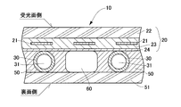
- FIG. 2 is a cross-sectional view of the hybrid solar cell module
- FIG. 3 is sectional drawing of the hybrid solar cell module of another form.
- the hybrid solar cell module 10 includes a solar panel 20 including solar cells 21 and a resin pipe 30 on the back side of the solar panel 20, which are bonded together by a rubber material 50 to be integrated. It is combined with. Then, a liquid such as water or antifreeze is poured into the resin pipe 30 and the temperature of the liquid poured into the resin pipe interior 31 is increased by using the solar heat taken in by the solar panel 20. Is. If the liquid is replaced with a silicone tube or a fluorine tube, oil can be considered.
- the hybrid solar cell module 10 includes a surface glass 22 of the solar cell panel 20 on the light receiving surface side and a back glass 51 on the back surface side, and the resin pipe 30 is enclosed by a rubber material layer 50.
- the apex portion of the resin pipe 30 is preferably in contact with the cell crack prevention sheet (back sheet) 24 and the back side glass 51 of the solar cell panel 20.
- the sealing material 23 is used for adhesion
- EVA ethylene-vinyl acetate copolymer
- an olefin-based sealing material filed by the applicant as Japanese Patent Application No. 2014-34405 on February 25, 2014 can be used.
- the resin pipe 30 having the characteristics of being excellent in corrosion resistance and being difficult to dissipate heat is adopted.
- the material of the resin pipe 30 may be polyethylene, silicone, fluorine-based, vinyl chloride or the like, but is preferably ethylene-based, and particularly preferably a cross-linked polyethylene pipe and a polybutene resin pipe.
- the water pressure resistance of the resin pipe 30 is required to be 0.2 MPa or more at 25 ° C. This is because the hybrid solar cell module 10 swells in the out-of-plane direction and there is a risk of destroying the hybrid solar cell module 10 if there is no such water pressure resistance.
- the rubber material 50 it is preferable to use olefin rubber.
- a material having an adhesive function is contained in the olefin rubber, and the resin pipe 30 and the rubber material 50 can be integrally bonded by heat received in the laminating process described later.
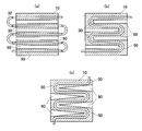
- FIG. 4 is a diagram for explaining the arrangement of resin pipes, where (a) shows a linear arrangement and (b) shows a meandering arrangement. Furthermore, FIG.4 (c) has shown another form of the hybrid solar cell module arranged meanderingly.
- the further heat insulation effect is improved by providing the air layer 60 between the resin pipes 30 adjacent to each other.
- the thickness of the air layer 60 is preferably about the outer diameter of the resin pipe 30. If the air layer 60 is provided, the weight of the hybrid solar cell module 10 itself can be reduced, and the amount of the rubber material 53 to be used can be reduced, so that a more economical module can be obtained. Considering such circumstances, it is effective to provide three or more air layers 60 for one hybrid solar cell module 10.
- FIG. 3 is a cross-sectional view of the hybrid solar cell module in which the air layer 60 portion has another form.
- a core is delivered to a portion corresponding to the air layer 60, manufactured by a laminating apparatus, and the core is removed.
- the air layer 60 is formed by inserting a plurality of high-strength core resin pipes 70 such as a crosslinked polyethylene resin or polybutene resin instead of the core.
- the core resin pipe 70 for forming the air layer 60 may be the same as the resin pipe 30 or may have a difference of about ⁇ 3 mm from the diameter of the resin pipe 30.
- the battery module 10 may be pulled out after manufacturing, or may be left as it is as shown in FIG.
- the hybrid solar cell module 10 manufactured as described above can simultaneously realize power generation using sunlight and supply of a liquid whose temperature has increased using solar heat. And it is possible to install using the frame etc. which are used for the conventional solar cell module as it is. Further, a conventional manufacturing apparatus (laminating apparatus) can be used for manufacturing the module itself. Furthermore, by providing the air layer 60, not only the heat insulation effect is improved, but also the amount of the rubber material 50 is reduced, which can contribute to further cost reduction and weight reduction.
Landscapes
- Engineering & Computer Science (AREA)
- Physics & Mathematics (AREA)
- Life Sciences & Earth Sciences (AREA)
- Sustainable Development (AREA)
- Sustainable Energy (AREA)
- Thermal Sciences (AREA)
- Chemical & Material Sciences (AREA)
- Combustion & Propulsion (AREA)
- Mechanical Engineering (AREA)
- General Engineering & Computer Science (AREA)
- Photovoltaic Devices (AREA)
Abstract
太陽電池モジュールに簡単な部材を追加するだけで、太陽光発電と同時に温水の供給を行うことができるハイブリッド太陽電池モジュールを提供する。 本発明のハイブリッド太陽電池モジュール10は、太陽光パネル20と、その太陽光パネル20の裏側に液体が通過する樹脂製パイプ30と、を有し、太陽光パネル20と樹脂製パイプ30とは一体的に結合されており、太陽光を利用した発電と、太陽熱を利用して温度上昇した液体の供給とを同時に実現するものであって、隣接する樹脂製パイプ30の間に空気層60を設けるとよい。
Description
本発明は、太陽光を利用した発電と太陽熱を利用した温水供給を同時に実現するハイブリッド太陽電池モジュールに関する。
太陽光発電は、自然エネルギーを活用する有効な発電システムとして広く浸透している。しかし、太陽光発電を実施するためには、広い受光面を必要とするため、その広い面積をさらに有効活用するために、太陽光発電に付加価値を設けることが検討されている。そのような付加価値の一つとして、太陽光発電システムに、温水供給システムを付加することが提案されている(特許文献1及び2参照)。
図5は、特許文献1に示された従来のソーラーシステムの取付断面図である。ここで、特許文献1に記載のソーラーシステムは、屋根R等の上に並べられた太陽光パネル100の中から一部のパネルを選択し、その下側のみに集熱管120や断熱材130を有するソーラー温水パネル110を設置するもので、ソーラー温水パネル110を最適な位置にレイアウトすることができるという効果を奏している。しかし、太陽光パネル100とソーラー温水パネル110は別々に製造されるため、既存の太陽光パネル100のフレーム150をそのまま用いることができない。つまり、ソーラー温水パネル110の台座160を別途設けることになるため、パネルの設置作業が煩雑である。
図6は、特許文献2に示された一体形成される太陽光熱電温水パネルの組立図である。特許文献2に記載の太陽光熱発電温水パネルでは、太陽光パネル100と集熱管120及び断熱材130を一体の構造としているため、従来のフレームに二つの機能を有するパネルを設置することができるという効果を奏している。
しかし、特許文献2ではほとんど検討されていないが、集熱管120には相当の耐水圧性能や長期間の耐久性が要求され、また、蓄熱性やパネル全体の強度などを十分に検討しなければ、一年中を通して、十分な温水を供給することは難しい。
このような実情に鑑み、本発明では、太陽光パネルと液体が通過する樹脂製パイプとを一体的に結合し、軽量かつ安価で、さらに長期間の使用に耐えられ、また、一年中を通して温水を供給することができるハイブリッド太陽電池モジュールを提供することを目的とする。
上記目的を達成するための第1発明のハイブリッド太陽電池モジュールは、太陽光の受光面側に設けられる太陽光パネルと、液体が通過する樹脂製パイプと、ゴム素材と、裏面側に設けられる裏面ガラスと、を一体的に結合してなり、前記樹脂製パイプは前記太陽光パネルの裏面及び前記裏面ガラスに接触しつつ前記ゴム素材によって包囲され、太陽光を利用した発電と、太陽熱を利用して前記樹脂製パイプ内を通過する液体の温度上昇とを同時に実現することを特徴とする。
第1発明のハイブリッド太陽電池モジュールを用いれば、従来の太陽電池モジュールに用いられるフレーム等を利用して、太陽光を利用した発電と太陽熱を利用して温度上昇した液体の供給とを同時に実現することができるという効果を奏する。
また第1発明のハイブリッド太陽電池モジュールは、太陽電池パネルの下部にゴム素材層を設け、その内部に樹脂製パイプが設けられたものであり、その樹脂製パイプに水等の液体を流通させ、太陽光により発電するとともに、太陽熱により温水等を製造する。温水等は樹脂製パイプを流通するので、従来の金属パイプを使用した場合に比べ腐食することがまったく無い。また従来の太陽電池パネルに樹脂製パイプを接着したものに比べ、樹脂製パイプがゴム素材層で覆われていて集熱性・熱伝導性・保温性に優れており、効率よく太陽熱により温水を製造することができる。
第2発明のハイブリッド太陽電池モジュールは、第1発明において以下の特徴を有する。前記ハイブリッド太陽電池モジュール1枚に対し、複数本または蛇行した形状の前記樹脂製パイプが設けられ、隣接する前記樹脂製パイプの間に、前記太陽光パネルの裏面、前記ゴム素材及び前記裏面ガラスによって囲まれて形成される空気層が設けられている。
第2発明のハイブリッド太陽電池モジュールを用いれば、温水等が流通する樹脂製パイプを包囲するゴム素材層の内部に空気層を設けているので、断熱効果が向上するだけでなく、ゴム素材の量を減少させるので、更なるコストダウンや軽量化にも寄与することができる。
第3発明のハイブリッド太陽電池モジュールは、第1発明において以下の特徴を有する。前記太陽光パネルは、表面ガラスと、太陽電池セルを内包する封止材と、セル割れ防止シートとを積層したものである。
第3発明のハイブリッド太陽電池モジュールを用いれば、太陽電池パネルとゴム素材層の間にセル割れ防止シートが挿入されている。従って第3発明のハイブリッド太陽電池モジュールを製造する際に真空加圧によるラミネ-ト加工により製造するが、その際に太陽電池パネルのセル割れを防止することができる。シートがクッション性を有しており衝撃力やプレス力が付加されても太陽電池パネルの太陽電池セルの割れを防止することができる。
第4発明のハイブリッド太陽電池モジュールは、第1発明または第2発明において以下の特徴を有する。前記樹脂製パイプが、架橋ポリエチレン樹脂或いはポリブテン樹脂からなる。
第4発明のハイブリッド太陽電池モジュールを用いれば、温水等が流通する樹脂製パイプを架橋ポリエチレン樹脂或いはポリブテン樹脂で構成しているので、耐圧性に優れ樹脂製パイプの破損・破裂等による温水等の漏れが発生する事のないハイブリッド太陽電池モジュールを実現することができる。またハイブリッド太陽電池モジュールを製造する際に、樹脂製パイプの潰れ防止をするためのテフロン(登録商標)樹脂棒等の中子が不要となる。
第5発明のハイブリッド太陽電池モジュールは、第1発明または第2発明において以下の特徴を有する。前記樹脂製パイプ内の耐水圧性能が25℃で、0.2MPa以上である。
第5発明によれば、第4発明と同様の効果が発現する。
第6発明のハイブリッド太陽電池モジュールは、第1発明または第2発明において以下の特徴を有する。前記ハイブリッド太陽電池モジュール1枚に対し、前記樹脂製パイプの全容積が100ccから8000ccである。
第6発明によれば、本発明のハイブリッド太陽電池モジュールにより所要の温水等を得ることができる。
第7発明のハイブリッド太陽電池モジュールは、第2発明において以下の特徴を有する。前記ハイブリッド太陽電池モジュール1枚に対し、前記空気層が3カ所以上設けられている。
第7発明によれば、第2発明と同様の効果を発現することができる。
第8発明のハイブリッド太陽電池モジュールは、第3発明において以下の特徴を有する。前記封止材は、オレフィン系封止材及び/又はエチレン-酢酸ビニル共重合体である。
第8発明によれば、封止材としてエチレン酢酸ビニル共重合体(EVA)を封止材として使用することができる。この場合、封止材は公知の封止材であり入手が容易である。またオレフィン系封止材は、出願人が2014年2月25日において特願2014-34405として出願したものである。このオレフィン系封止材を使用することにより、封止材としてEVAを使用した場合に比べて太陽電池パネルの発電中に酢酸の発生が非常に少なく、太陽電池パネル内の電極が腐食することがない。更にこのオレフィン系封止材と太陽電池パネルの表面側ガラスとの間にEVA封止材を設ける構成とすることも可能である。
第9発明のハイブリッド太陽電池モジュールは、第3発明において以下の特徴を有する。前記セル割れ防止シートは、太陽電池用バックシートとオレフィン系ゴム組成物とを一体化したものである。
第9発明によれば、太陽電池パネルに使用するバックシートにオレフィンゴム組成物を一体化したセル割れ防止シートを使用している。このオレフィン系ゴム組成物は、出願人が2014年2月25日において特願2014-34580として出願したものである。このオレフィン系ゴム組成物をセル割れ防止シートとして使用することにより、第3発明と同様の効果が発現する。またこのセル割れ防止シートをハイブリッド太陽電池モジュールに使用することにより、ハイブリッド太陽電池モジュールの使用中に外的要因により衝撃力が加えられても太陽電池セルが割れることながなく発電機能を維持しながら温水等の製造をすることができる。
第10発明のハイブリッド太陽電池モジュールは、第1発明において以下の特徴を有する。前記ハイブリッド太陽電池モジュール1枚に対し、平行に複数本の前記樹脂製パイプが設けられ、前記ハイブリッド太陽電池モジュールの外側において前記樹脂製パイプが互いに連結されることで、複数本の前記樹脂製パイプが1本に繋がれている。
第10発明によれば、ハイブリッド太陽電池モジュール内に設けられた複数本の樹脂製パイプの隣接するもの同士が連結されているので温水等がハイブリッド太陽電池モジュール内を繰り返し流通することになり1枚のハイブリッド太陽電池モジュールでも温水等製造することができる。
第11発明のハイブリッド太陽電池モジュールは、第9発明において以下の特徴を有する。前記オレフィン系ゴム組成物のシート厚みが300μm以上で800μm以下である。
第11発明によれば、太陽電池パネルとゴム素材層との間に設けられたオレフィン系ゴム組成物の厚みが300μm以上で800μm以下であり、ハイブリッド太陽電池モジュールを製造する際のラミネート加工におけるプレス力により太陽電池パネル内の太陽電池セルが割れることは無い。
このオレフィン系ゴム組成物の厚みが300μm未満においては、ハイブリッド太陽電池モジュールを製造する際のラミネート加工時のプレス力により太陽電池セルが割れてしまう虞がある。また、このオレフィン系ゴム組成物の厚みが800μmを超えると結晶系セル表面にゴム組成物が回り込み、発電の阻害となることがあるため、好ましくない。
このオレフィン系ゴム組成物の厚みが300μm未満においては、ハイブリッド太陽電池モジュールを製造する際のラミネート加工時のプレス力により太陽電池セルが割れてしまう虞がある。また、このオレフィン系ゴム組成物の厚みが800μmを超えると結晶系セル表面にゴム組成物が回り込み、発電の阻害となることがあるため、好ましくない。
第12発明のハイブリッド太陽電池モジュールは、第2発明において以下の特徴を有する。前記空気層は、樹脂ホースを1本或いは複数本並べて得られる空間である。
第12発明によれば、ハイブリッド太陽電池モジュールの空気層を形成するためにゴム素材層と隣接して樹脂ホースを1本或いは複数本並べているので、空気層を形成するために中子の抜き取りが不要である。従って本発明のハイブリッド太陽電池モジュールの製造効率を大幅に向上させることができる。
第13発明のハイブリッド太陽電池モジュールは、第12発明において以下の特徴を有する。前記樹脂ホースが、架橋ポリエチレン樹脂或いはポリブテン樹脂である。
第13発明によれば、空気層中に埋設された樹脂ホースが架橋ポリエチレン樹脂或いはポリブテン樹脂を使用しているので、空気層に相当する空間に当該ホースを配置し、ハイブリッド太陽電池モジュールを製造する際に加えられるプレス力に対して十分な強度を有しており所要の空気層を形成することができる。
以下、本発明の実施の形態を添付図面を参照しながら説明する。
図1は、ハイブリッド太陽電池モジュールの斜視図であり、また、図2は、ハイブリッド太陽電池モジュールの断面図である。また図3は、別形態のハイブリッド太陽電池モジュールの断面図である。このハイブリッド太陽電池モジュール10は、太陽電池セル21を備えた太陽光パネル20と、その太陽光パネル20の裏側に樹脂製パイプ30を有しており、これらをゴム素材50によって接着して一体的に結合したものである。そして、この樹脂製パイプ30に水や不凍液などの液体を流し込み、太陽光パネル20が取り込んだ太陽熱を利用して、樹脂製パイプ内部31に流し込まれた液体の温度を上昇させることを目的とするものである。液体の種類としては、シリコーンチューブやフッ素チューブに置き換えれば、油等も考えられるが、通常は、水の場合には、温水を供給することになるので、浴場施設のような温水を大量に必要とする施設だけで利用するのではなく、一般家庭でも利用することができる。不凍液を使用する場合は、熱交換機にて、上水道系の水を温水とする。希望の温度に満たない場合は、ボイラーで追い炊きするシステムで、快適に、経済的に温水を製造できる。
このハイブリッド太陽電池モジュール10は、受光面側には太陽電池パネル20の表面ガラス22、裏面側に裏面ガラス51を備えて、樹脂製パイプ30はゴム素材層50により内包した構成となっている。尚構造的には、樹脂製パイプ30の頂点部分は太陽電池パネル20のセル割れ防止シート(バックシート)24及び裏面側ガラス51と接触していることが好ましい。このようなガラスで内包する構成にすることで、蓄熱効果を高め、さらにハイブリッド太陽電池モジュール10全体の強度を強くすることができる。なお、太陽光パネル20の表面ガラス22と太陽電池セル21及びセル割れ防止シート24の接着及び封止には封止材23が用いられている。この封止材23としては、EVA(エチレン―酢酸ビニル共重合体)を用いるのがよい。またこの封止材としては、出願人が2014年2月25日において特願2014-34405として出願したオレフィン系封止材を使用することができる。
従来、このような太陽熱を吸収する集熱管としては、銅製のものが用いられてきた。しかし、太陽光パネル20と一体化する場合には、長期間の使用に耐えられなければならないことと、銅製の場合には放熱が早いため、特に温水を必要とする冬場には十分な蓄熱ができず、温水を供給するという効果を果たすことが難しくなる。そこで、本発明では、耐蝕性に優れ、かつ、放熱しにくいという特徴を持つ樹脂製パイプ30を採用することとしている。樹脂製パイプ30の素材としては、ポリエチレン、シリコーン、フッ素系、塩ビ等を用いることができるが、好ましくはエチレン系で、特に架橋ポリエチレンパイプ及びポリブテン樹脂パイプを用いるのが最適である。
なお、樹脂製パイプ30の耐水圧性能としては、25℃で、0.2MPa以上が必要となる。これだけの耐水圧性能がなければ、ハイブリッド太陽電池モジュール10は面外方向に膨らみ、ハイブリッド太陽電池モジュール10を破壊する恐れがあるためである。
また、1枚のハイブリッド太陽電池モジュール10に対し、樹脂製パイプ30の容積が100cc以上なければ、一般家庭での使用に対し、十分な量の温水を供給することができない。また、容積が8000cc以上となると、樹脂製パイプ30の径が大きくなり過ぎて、モジュールの強度等に問題が生じることから、本発明では、1枚のハイブリッド太陽電池モジュール10に対し、100cc以上で8000cc以下を最適な樹脂製パイプ30の容積と考える。
ゴム素材50としては、好ましくはオレフィン系ゴムを用いるのがよい。オレフィン系ゴムに接着機能を有する素材を含有させ、後述するラミネート加工において受ける熱により樹脂製パイプ30とゴム素材50を一体的に接着することができる。
図4は、樹脂製パイプの配置を説明する図であって、(a)は直線配置、(b)は蛇行配置を示す。更に図4(c)は、蛇行配置したハイブリッド太陽電池モジュールの別形態を示している。
図4(a)の樹脂製パイプ30の配置方法は、ハイブリッド太陽電池モジュール10の表面全体から太陽熱を取り入れることができるように、1枚のハイブリッド太陽電池モジュール10に対し、図4(a)のように複数本の樹脂製パイプ10を平行に並べている。平行に設置された各樹脂製パイプ30は、隣接する樹脂製パイプ30の先端同士をそれぞれジョイント32により接続されている。また別のモジュールとも接続することが容易であり、設置の際の配管作業も容易である。このように樹脂製パイプを配置することにより大量の温水等を製造することができる。このような樹脂製パイプ30の配置方法は、後述する空気層60を形成する面においてハイブリッド太陽電池モジュール10の製造がしやすく最も好ましい形態である。
また図4(b)、図4(c)のように樹脂製パイプ30を蛇行した配置で設ける構成も可能である。
また、これらの配置の場合には、モジュール内において隣接する樹脂製パイプ30同士が平行に設けられることになる。そこで、隣接する樹脂製パイプ30同士の間に空気層60を設けることで、更なる断熱効果の向上が図られる。なお、空気層60の厚さとしては、樹脂製パイプ30の外径程度とするのがよい。そして、空気層60を設ければ、それだけハイブリッド太陽電池モジュール10そのものの重量が軽くなり、かつ、使用するゴム素材53の量も減らすことができるので、より経済的なモジュールとすることができる。このような実情から考えて、1枚のハイブリッド太陽電池モジュール10に対して、3カ所以上の空気層60を設けるのが効果的である。
以下に本発明のハイブリッド太陽電池モジュールの製造方法について簡単に説明する。本発明に係るハイブリッド太陽電池モジュール10は、ラミネート装置により真空雰囲気において加圧プレスして製造される。太陽電池パネル20の構成部材、ゴム素材、樹脂製パイプ及び裏面ガラス積層配置して製造される。従って、加圧プレスする際に、樹脂製パイプ30や空気層60は、そのままでは潰れてしまう恐れがある。そこで空気層60は、相当する部分にアルミ等の金属製の中子を詰めておき、プレス後に抜き取るという方法で形成される。また、樹脂製パイプについては、塩を詰めておき、プレス後に流し取るという方法を採用することもできるし、樹脂製パイプ30の形状を図4(a)のように直線配置とし、プレス前にテフロン(登録商標)樹脂棒を樹脂製パイプ内部31に詰めておいて、プレス後に引き抜くという方法を採用することでも良い。なお、図3(b)のように樹脂製パイプ30が蛇行して配置した場合には、テフロン(登録商標)樹脂棒では対応できないので、このような場合には、塩を詰める方法を採用すると確実に水路を確保できる。
図3は、ハイブリッド太陽電池モジュールの空気層60部分を別形態としたものの断面図である。図2の形態のハイブリッド太陽電池モジュールの場合は空気層60に相当する部分に中子を納入しラミネート装置にて製造し中子を抜いていた。一方図3の形態の場合は、中子の代わりに架橋ポリエチレン樹脂やポリブテン樹脂のような高強度な中子用樹脂パイプ70を複数本挿入して空気層60を形成している。この空気層60を形成するための中子用樹脂パイプ70は、樹脂製パイプ30と同じものでも良いし、樹脂製パイプ30の径に対し±3mm程度違いがあるものでも良く、また、ハイブリッド太陽電池モジュール10製造後引き抜いても良いし、図3のようにそのまま残しておいても良い。
以上のようにして製造されたハイブリッド太陽電池モジュール10は、太陽光を利用した発電と太陽熱を利用して温度上昇した液体の供給とを同時に実現することができる。そして、従来の太陽電池モジュールに用いられるフレーム等をそのまま利用して設置することが可能である。また、モジュールそのものの製造に関しても、従来の製造装置(ラミネート装置)を使用することが可能である。さらに、空気層60を設けることで、断熱効果が向上するだけでなく、ゴム素材50の量を減少させるので、更なるコストダウンや軽量化にも寄与することができる。
10 ハイブリッド太陽電池モジュール
20 太陽光パネル
21 太陽電池セル
22 表面ガラス
23 封止材
24 セル割れ防止シート
30 樹脂製パイプ
31 パイプ内部
50 ゴム素材
51 裏面ガラス
60 空気層
70 中子用樹脂パイプ
20 太陽光パネル
21 太陽電池セル
22 表面ガラス
23 封止材
24 セル割れ防止シート
30 樹脂製パイプ
31 パイプ内部
50 ゴム素材
51 裏面ガラス
60 空気層
70 中子用樹脂パイプ
Claims (13)
- 太陽光の受光面側に設けられる太陽光パネルと、液体が通過する樹脂製パイプと、ゴム素材と、裏面側に設けられる裏面ガラスと、を一体的に結合してなり、前記樹脂製パイプは前記太陽光パネルの裏面及び前記裏面ガラスに接触しつつ前記ゴム素材によって包囲され、太陽光を利用した発電と、太陽熱を利用して前記樹脂製パイプ内を通過する液体の温度上昇とを同時に実現することを特徴とするハイブリッド太陽電池モジュール。
- 前記ハイブリッド太陽電池モジュール1枚に対し、複数本または蛇行した形状の前記樹脂製パイプが設けられ、隣接する前記樹脂製パイプの間に、前記太陽光パネルの裏面、前記ゴム素材及び前記裏面ガラスによって囲まれて形成される空気層が設けられていることを特徴とする請求項1に記載のハイブリッド太陽電池モジュール。
- 前記太陽光パネルは、表面ガラスと、太陽電池セルを内包する封止材と、セル割れ防止シートとを積層したものであることを特徴とする請求項1に記載のハイブリッド太陽電池モジュール。
- 前記樹脂製パイプが、架橋ポリエチレン樹脂或いはポリブテン樹脂からなることを特徴とする請求項1又は2に記載のハイブリッド太陽電池モジュール。
- 前記樹脂製パイプ内の耐水圧性能が、0.2MPa以上であることを特徴とする請求項1又は2のいずれかに記載のハイブリッド太陽電池モジュール。
- 前記ハイブリッド太陽電池モジュール1枚に対し、前記樹脂製パイプの全容積が100ccから8000ccであることを特徴とする請求項1又は2のいずれかに記載のハイブリッド太陽電池モジュール。
- 前記ハイブリッド太陽電池モジュール1枚に対し、前記空気層が3カ所以上設けられていることを特徴とする請求項2に記載のハイブリッド太陽電池モジュール。
- 前記封止材は、オレフィン系封止材又はエチレン-酢酸ビニル共重合体からなることを特徴とする請求項3に記載のハイブリッド太陽電池モジュール。
- 前記セル割れ防止シートは、太陽電池用バックシートとオレフィン系ゴム組成物とを一体化したものであることを特徴とする請求項3に記載のハイブリッド太陽電池モジュール。
- 前記ハイブリッド太陽電池モジュール1枚に対し、平行に複数本の前記樹脂製パイプが設けられ、前記ハイブリッド太陽電池モジュールの外側において前記樹脂製パイプが互いに連結されることで、複数本の前記樹脂製パイプが1本に繋がることを特徴とする請求項1に記載のハイブリッド太陽電池モジュール。
- 前記オレフィン系ゴム組成物のシート厚みが300μm以上で800μm以下であることを特徴とする請求項9に記載のハイブリッド太陽電池モジュール。
- 前記空気層は、中子用樹脂パイプを1本或いは複数本並べて得られる空間であることを特徴とする請求項2に記載のハイブリッド太陽電池モジュール。
- 前記中子用樹脂パイプが、架橋ポリエチレン樹脂或いはポリブテン樹脂からなることを特徴とする請求項12に記載のハイブリッド太陽電池モジュール。
Applications Claiming Priority (2)
| Application Number | Priority Date | Filing Date | Title |
|---|---|---|---|
| JP2015029594A JP6474632B2 (ja) | 2015-02-18 | 2015-02-18 | ハイブリッド太陽電池モジュール |
| JP2015-029594 | 2015-02-18 |
Publications (1)
| Publication Number | Publication Date |
|---|---|
| WO2016133003A1 true WO2016133003A1 (ja) | 2016-08-25 |
Family
ID=56692511
Family Applications (1)
| Application Number | Title | Priority Date | Filing Date |
|---|---|---|---|
| PCT/JP2016/054039 Ceased WO2016133003A1 (ja) | 2015-02-18 | 2016-02-11 | ハイブリッド太陽電池モジュール |
Country Status (2)
| Country | Link |
|---|---|
| JP (1) | JP6474632B2 (ja) |
| WO (1) | WO2016133003A1 (ja) |
Cited By (1)
| Publication number | Priority date | Publication date | Assignee | Title |
|---|---|---|---|---|
| JP2017022793A (ja) * | 2015-07-07 | 2017-01-26 | 日清紡メカトロニクス株式会社 | ハイブリッド太陽電池モジュール |
Families Citing this family (5)
| Publication number | Priority date | Publication date | Assignee | Title |
|---|---|---|---|---|
| CN106549635A (zh) * | 2016-11-04 | 2017-03-29 | 东莞市联洲知识产权运营管理有限公司 | 一种具有良好散热功能的太阳能电池模块 |
| CN109282506B (zh) * | 2018-09-25 | 2020-11-20 | 嘉兴巨腾信息科技有限公司 | 一种多效太阳能利用系统 |
| KR102168493B1 (ko) * | 2018-11-29 | 2020-10-21 | (주)이맥스시스템 | 태양광열 발전용 패널 |
| CN110993712B (zh) * | 2019-11-29 | 2021-10-22 | 泰州隆基乐叶光伏科技有限公司 | 光伏层压件、光伏组件及光伏屋顶 |
| WO2024030193A2 (en) * | 2022-06-13 | 2024-02-08 | Icarus Rt, Inc. | Hybrid photovoltaic-thermal and co-generation system |
Citations (4)
| Publication number | Priority date | Publication date | Assignee | Title |
|---|---|---|---|---|
| JPH10325618A (ja) * | 1997-03-26 | 1998-12-08 | Sekisui Chem Co Ltd | 給湯装置 |
| JP2004176982A (ja) * | 2002-11-26 | 2004-06-24 | Sekisui Chem Co Ltd | 太陽電池組込み集熱ハイブリッドモジュール |
| JP2013115224A (ja) * | 2011-11-29 | 2013-06-10 | Noritz Corp | 発電熱交換ハイブリッドパネル |
| JP2014177895A (ja) * | 2013-03-14 | 2014-09-25 | Chicony Power Technology Co Ltd | 複合型光熱発電装置 |
-
2015
- 2015-02-18 JP JP2015029594A patent/JP6474632B2/ja not_active Expired - Fee Related
-
2016
- 2016-02-11 WO PCT/JP2016/054039 patent/WO2016133003A1/ja not_active Ceased
Patent Citations (4)
| Publication number | Priority date | Publication date | Assignee | Title |
|---|---|---|---|---|
| JPH10325618A (ja) * | 1997-03-26 | 1998-12-08 | Sekisui Chem Co Ltd | 給湯装置 |
| JP2004176982A (ja) * | 2002-11-26 | 2004-06-24 | Sekisui Chem Co Ltd | 太陽電池組込み集熱ハイブリッドモジュール |
| JP2013115224A (ja) * | 2011-11-29 | 2013-06-10 | Noritz Corp | 発電熱交換ハイブリッドパネル |
| JP2014177895A (ja) * | 2013-03-14 | 2014-09-25 | Chicony Power Technology Co Ltd | 複合型光熱発電装置 |
Cited By (1)
| Publication number | Priority date | Publication date | Assignee | Title |
|---|---|---|---|---|
| JP2017022793A (ja) * | 2015-07-07 | 2017-01-26 | 日清紡メカトロニクス株式会社 | ハイブリッド太陽電池モジュール |
Also Published As
| Publication number | Publication date |
|---|---|
| JP6474632B2 (ja) | 2019-02-27 |
| JP2016152711A (ja) | 2016-08-22 |
Similar Documents
| Publication | Publication Date | Title |
|---|---|---|
| JP6474632B2 (ja) | ハイブリッド太陽電池モジュール | |
| US11619423B2 (en) | All-in-one integrated multifunctional triple power module | |
| EP3316478B1 (en) | All-in-one integrated multifunctional triple power module "itm" | |
| KR101909405B1 (ko) | 하이브리드 태양전지 모듈 | |
| JP5589201B2 (ja) | ヒートシンク付き太陽光コジェネレイションモジュール | |
| CN102646742A (zh) | 平板热管太阳能光伏光热复合集热器及其制作工艺 | |
| KR101803832B1 (ko) | 액체식 pvt 컬렉터 | |
| WO2011014120A2 (en) | Multiple functional roof and wall system | |
| JP2009534560A (ja) | エネルギー変換システム | |
| WO2014132197A2 (en) | Encapsulation materials and design of an integrated photovoltaic and thermal module (pvt) | |
| KR102168493B1 (ko) | 태양광열 발전용 패널 | |
| WO2010127661A3 (de) | Solaranlage zur erzeugung elektrischer und thermischer energie | |
| JP5747949B2 (ja) | 太陽光熱電併給パネル | |
| JP6552893B2 (ja) | ハイブリッド太陽電池モジュール | |
| JP5568035B2 (ja) | 太陽光利用による複合発電装置 | |
| CN201000896Y (zh) | 水冷式光伏发电系统 | |
| EP2665877A1 (en) | Composite building panel with thermoelectric generator means | |
| CN102544178A (zh) | 光伏发电集热装置 | |
| KR20110122544A (ko) | 하이브리드 태양열 집열기 | |
| CN103814446A (zh) | 改善混合太阳能模块的寿命和人机工程学 | |
| WO2011138737A1 (en) | Heating device | |
| JP2002089971A (ja) | 太陽エネルギ利用システム | |
| CN102383544A (zh) | 一种带热发电装置的多用途太阳能坡屋面系统 |
Legal Events
| Date | Code | Title | Description |
|---|---|---|---|
| 121 | Ep: the epo has been informed by wipo that ep was designated in this application |
Ref document number: 16752389 Country of ref document: EP Kind code of ref document: A1 |
|
| NENP | Non-entry into the national phase |
Ref country code: DE |
|
| 122 | Ep: pct application non-entry in european phase |
Ref document number: 16752389 Country of ref document: EP Kind code of ref document: A1 |