WO2016135881A1 - Système d'affichage, procédé d'affichage et programme d'affichage - Google Patents
Système d'affichage, procédé d'affichage et programme d'affichage Download PDFInfo
- Publication number
- WO2016135881A1 WO2016135881A1 PCT/JP2015/055396 JP2015055396W WO2016135881A1 WO 2016135881 A1 WO2016135881 A1 WO 2016135881A1 JP 2015055396 W JP2015055396 W JP 2015055396W WO 2016135881 A1 WO2016135881 A1 WO 2016135881A1
- Authority
- WO
- WIPO (PCT)
- Prior art keywords
- video
- signal
- display device
- video signal
- unit
- Prior art date
- Legal status (The legal status is an assumption and is not a legal conclusion. Google has not performed a legal analysis and makes no representation as to the accuracy of the status listed.)
- Ceased
Links
Images




Classifications
-
- G—PHYSICS
- G06—COMPUTING OR CALCULATING; COUNTING
- G06F—ELECTRIC DIGITAL DATA PROCESSING
- G06F3/00—Input arrangements for transferring data to be processed into a form capable of being handled by the computer; Output arrangements for transferring data from processing unit to output unit, e.g. interface arrangements
- G06F3/14—Digital output to display device ; Cooperation and interconnection of the display device with other functional units
- G06F3/1415—Digital output to display device ; Cooperation and interconnection of the display device with other functional units with means for detecting differences between the image stored in the host and the images displayed on the displays
-
- G—PHYSICS
- G06—COMPUTING OR CALCULATING; COUNTING
- G06F—ELECTRIC DIGITAL DATA PROCESSING
- G06F3/00—Input arrangements for transferring data to be processed into a form capable of being handled by the computer; Output arrangements for transferring data from processing unit to output unit, e.g. interface arrangements
- G06F3/14—Digital output to display device ; Cooperation and interconnection of the display device with other functional units
- G06F3/1423—Digital output to display device ; Cooperation and interconnection of the display device with other functional units controlling a plurality of local displays, e.g. CRT and flat panel display
- G06F3/1446—Digital output to display device ; Cooperation and interconnection of the display device with other functional units controlling a plurality of local displays, e.g. CRT and flat panel display display composed of modules, e.g. video walls
-
- G—PHYSICS
- G09—EDUCATION; CRYPTOGRAPHY; DISPLAY; ADVERTISING; SEALS
- G09G—ARRANGEMENTS OR CIRCUITS FOR CONTROL OF INDICATING DEVICES USING STATIC MEANS TO PRESENT VARIABLE INFORMATION
- G09G5/00—Control arrangements or circuits for visual indicators common to cathode-ray tube indicators and other visual indicators
- G09G5/003—Details of a display terminal, the details relating to the control arrangement of the display terminal and to the interfaces thereto
- G09G5/006—Details of the interface to the display terminal
-
- H—ELECTRICITY
- H04—ELECTRIC COMMUNICATION TECHNIQUE
- H04N—PICTORIAL COMMUNICATION, e.g. TELEVISION
- H04N9/00—Details of colour television systems
- H04N9/77—Circuits for processing the brightness signal and the chrominance signal relative to each other, e.g. adjusting the phase of the brightness signal relative to the colour signal, correcting differential gain or differential phase
-
- G—PHYSICS
- G09—EDUCATION; CRYPTOGRAPHY; DISPLAY; ADVERTISING; SEALS
- G09G—ARRANGEMENTS OR CIRCUITS FOR CONTROL OF INDICATING DEVICES USING STATIC MEANS TO PRESENT VARIABLE INFORMATION
- G09G2320/00—Control of display operating conditions
- G09G2320/02—Improving the quality of display appearance
- G09G2320/0233—Improving the luminance or brightness uniformity across the screen
-
- G—PHYSICS
- G09—EDUCATION; CRYPTOGRAPHY; DISPLAY; ADVERTISING; SEALS
- G09G—ARRANGEMENTS OR CIRCUITS FOR CONTROL OF INDICATING DEVICES USING STATIC MEANS TO PRESENT VARIABLE INFORMATION
- G09G2320/00—Control of display operating conditions
- G09G2320/02—Improving the quality of display appearance
- G09G2320/0271—Adjustment of the gradation levels within the range of the gradation scale, e.g. by redistribution or clipping
-
- G—PHYSICS
- G09—EDUCATION; CRYPTOGRAPHY; DISPLAY; ADVERTISING; SEALS
- G09G—ARRANGEMENTS OR CIRCUITS FOR CONTROL OF INDICATING DEVICES USING STATIC MEANS TO PRESENT VARIABLE INFORMATION
- G09G2320/00—Control of display operating conditions
- G09G2320/06—Adjustment of display parameters
- G09G2320/0673—Adjustment of display parameters for control of gamma adjustment, e.g. selecting another gamma curve
-
- G—PHYSICS
- G09—EDUCATION; CRYPTOGRAPHY; DISPLAY; ADVERTISING; SEALS
- G09G—ARRANGEMENTS OR CIRCUITS FOR CONTROL OF INDICATING DEVICES USING STATIC MEANS TO PRESENT VARIABLE INFORMATION
- G09G2340/00—Aspects of display data processing
- G09G2340/04—Changes in size, position or resolution of an image
- G09G2340/0407—Resolution change, inclusive of the use of different resolutions for different screen areas
-
- G—PHYSICS
- G09—EDUCATION; CRYPTOGRAPHY; DISPLAY; ADVERTISING; SEALS
- G09G—ARRANGEMENTS OR CIRCUITS FOR CONTROL OF INDICATING DEVICES USING STATIC MEANS TO PRESENT VARIABLE INFORMATION
- G09G2360/00—Aspects of the architecture of display systems
- G09G2360/16—Calculation or use of calculated indices related to luminance levels in display data
-
- G—PHYSICS
- G09—EDUCATION; CRYPTOGRAPHY; DISPLAY; ADVERTISING; SEALS
- G09G—ARRANGEMENTS OR CIRCUITS FOR CONTROL OF INDICATING DEVICES USING STATIC MEANS TO PRESENT VARIABLE INFORMATION
- G09G2370/00—Aspects of data communication
- G09G2370/04—Exchange of auxiliary data, i.e. other than image data, between monitor and graphics controller
- G09G2370/045—Exchange of auxiliary data, i.e. other than image data, between monitor and graphics controller using multiple communication channels, e.g. parallel and serial
-
- G—PHYSICS
- G09—EDUCATION; CRYPTOGRAPHY; DISPLAY; ADVERTISING; SEALS
- G09G—ARRANGEMENTS OR CIRCUITS FOR CONTROL OF INDICATING DEVICES USING STATIC MEANS TO PRESENT VARIABLE INFORMATION
- G09G2370/00—Aspects of data communication
- G09G2370/10—Use of a protocol of communication by packets in interfaces along the display data pipeline
-
- G—PHYSICS
- G09—EDUCATION; CRYPTOGRAPHY; DISPLAY; ADVERTISING; SEALS
- G09G—ARRANGEMENTS OR CIRCUITS FOR CONTROL OF INDICATING DEVICES USING STATIC MEANS TO PRESENT VARIABLE INFORMATION
- G09G2370/00—Aspects of data communication
- G09G2370/12—Use of DVI or HDMI protocol in interfaces along the display data pipeline
-
- G—PHYSICS
- G09—EDUCATION; CRYPTOGRAPHY; DISPLAY; ADVERTISING; SEALS
- G09G—ARRANGEMENTS OR CIRCUITS FOR CONTROL OF INDICATING DEVICES USING STATIC MEANS TO PRESENT VARIABLE INFORMATION
- G09G5/00—Control arrangements or circuits for visual indicators common to cathode-ray tube indicators and other visual indicators
- G09G5/10—Intensity circuits
Definitions
- the present invention relates to a display device, a display system, a display method, and a display program.
- a multi-screen display device that includes a plurality of video display units and transmits a command to start brightness correction processing to a slave device when the power is turned on.
- a display in which a plurality of displays are connected in a daisy chain, and a video signal supplied from a signal source is sequentially sent from a front display to a rear display.
- a liquid crystal television apparatus that automatically determines whether the signal standard of an input signal is a full range or a limit range.
- a video display device that sequentially measures the luminance level one horizontal line at a time from the top of the video signal screen.
- Some video input signals input to the display device include video-related information such as scaling, which is information indicating the video gradation information and the video display range.
- video-related information such as scaling, which is information indicating the video gradation information and the video display range.
- a High-Definition Multimedia Interface (HDMI) (registered trademark) signal which is one of video input signals, includes Infoframe information including AVI (Auxiliary Video Information) as video related information.
- the AVI includes, for example, a parameter of “RGB Quantization Range” indicating whether the gradation range of the RGB signal is a limited range of 16 to 235 or a full range of 0 to 256. Further, the AVI includes a “Scan Information” parameter indicating video scaling.
- the display device to which the HDMI signal is input can check the Infoframe information included in the video input signal and adjust the gradation and scaling of the video to be displayed.
- the video input of the preceding display device is aimed at reducing the number of video distributors that distribute the video input signal.
- a video signal is output from a DP (Display Port)
- video related information cannot be included in the video signal output from the DP. Therefore, even when the video input signal includes video related information like the HDMI signal, the video related information of the HDMI signal is not input to the subsequent monitor.
- the display device in the previous stage can adjust the display video based on the video related information included in the input video input signal, whereas the display device in the subsequent stage in which the video signal lacking the video related information is input.
- the display image cannot be adjusted based on the image related information. Therefore, the video displayed on the front display device may be different from the video displayed on the rear display device.
- the video-related information includes information on the gradation range of the RGB signal
- the display device in the subsequent stage cannot adjust the gradation range
- the color of the video displayed on the display device in the subsequent stage is displayed on the monitor in the previous stage. In some cases, it may differ from the image color.
- an advantage of some aspects of the invention is that it provides a display device, a display system, a display method, and a display program that enable adjustment of a display image in a display device to which a video input signal is not directly input.
- a display device includes a video input unit that receives a video signal based on a video input signal received by another display device, and communication data indicating a change in the video input signal. Based on the communication data received by the communication control unit, the video signal determination unit for determining the video signal input from the video input unit, and the determination result of the video signal determination unit And a video signal adjusting unit for adjusting the video signal.
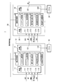
- FIG. 1 is a functional block diagram illustrating a configuration of a display system 1 exemplified as the first embodiment.
- the display system 1 includes a first display device 10 exemplified as a first display device, a second display device 20 exemplified as a second and subsequent display devices, and a communication control line 30. .
- a display system including two display devices, the first display device 10 and the second display device 20, is illustrated, but the third and subsequent display devices are daisy chained in the subsequent stage of the second display device 20. Connected to form a display system.
- the first display device 10 and the second display device 20 have the same device configuration. That is, in the first embodiment, the display system can be configured with the first display device to which a video input signal is input as the first display device and the same display device as the second and subsequent display devices. Illustrated. By configuring a display system with display devices having the same device configuration, the display devices can be arranged without worrying about the connection order of which display devices.
- the first display device 10 includes a video input unit 11, a video output unit 12, a communication control unit 13, a system control unit 14, a command transmission / reception unit 15, a signal change detection unit 16, a video signal determination unit 17, and a video signal adjustment unit 18. And a panel 19.
- the video input unit 11 includes a DVI (Digital Visual Interface) input unit 111, a DP input unit 112, an HDMI input unit 113, an HD-BaseT (registered trademark) input unit 114, and an SDI (Serial Digital Interface) input unit 115.
- FIG. 1 illustrates the case where the panel 19 is configured to be connected to the outside of the first display device 10, the panel 19 is included in the display device 10.
- the display device of the present embodiment may be a device that does not include a panel and controls display of the panel. The same applies to the panel 29 in the second display device 20 described below.
- the second display device 20 includes a video input unit 21, a video output unit 22, a communication control unit 23, a system control unit 24, a command transmission / reception unit 25, a signal change detection unit 26, a video signal determination unit 27, and a video signal adjustment unit 28. And a panel 29.
- the video input unit 21 includes a DVI input unit 211, a DP input unit 212, an HDMI input unit 213, an HD-BaseT input unit 214, and an SDI input unit 215.
- the communication control line 30 is a control line that connects the first display device 10 and the second display device 20 in a communicable manner.
- a priority LAN Local Area
- Ethernet registered trademark
- the communication control line 30 may be connected to a PC (not shown) or a third or subsequent display device.
- the video input unit 11 has interfaces for video input signals of the DVI input unit 111, the DP input unit 112, the HDMI input unit 113, the HD-BaseT input unit 114, and the SDI input unit 115.
- the input cable can be connected.
- the video input unit 11 can switch the plurality of types of video input signals that are input. Switching of the video input signal can be performed by an explicit selection operation such as a button operation by the user.
- the video input signal can be switched by the video input unit 11 detecting the physical connection of the input cable or detecting the input of the video input signal.
- the video output unit 12 includes a DP output unit 121 and a panel connection unit 122.
- the video signal output from the DP output unit 121 and the panel connection unit 122 is a DP signal.
- the DP signal output from the DP output unit 121 is input to the DP input unit 212 of the video input unit 21 of the second display device. That is, it is assumed that DP signals are input from the preceding display device to the second and subsequent display devices by daisy chain connection.
- the video signal output from the panel connection unit 122 is output to the panel 19.
- the 1st display system 1 has illustrated the case where the 2nd display apparatus 20 is connected as a display apparatus after the 2nd unit.
- the configuration of the device may be a configuration in which three or more display devices are connected.
- the video output unit and the video input unit are connected one-to-one, and a case where a video signal is transmitted by so-called daisy chain connection in which a plurality of display devices are connected in a row is illustrated.
- one video output unit may be connected to a plurality of video input units to transmit a video signal.
- the relationship between the video input signal input from the video input unit 11 and the video signal output from the video output unit 12 will be described.
- the video input signal input from the video input unit 11 is an HDMI signal
- a distributor is required in order to distribute the HDMI signal and output it to the subsequent display device.
- a display device capable of inputting a plurality of types of video input signals as the number of types of video input signals increases, it is necessary to provide a distributor according to the number of video input signals, resulting in an increase in cost.
- a large display system such as a public display
- a large number of display devices are used.
- the number of distributors can be reduced by inputting a single video signal such as a DP signal or a DVI signal through daisy chain connection.
- the video related information included in the video input signal input to the first unit may not be included in the output video signal.
- the output video signal lacks HDMI video related information.
- the communication control unit 13 communicates with the communication control unit 23 of the second display device 20 via the communication control line 30.
- the communication control unit 13 is a network controller, for example.
- the communication control unit 13 transmits communication data indicating a change in the video input signal input to the video input unit 11 to the communication control unit 23.
- Communication data transmitted by the communication control unit 13 can be transmitted in a communication procedure based on the communication protocol of the communication control line 30.
- the communication control unit 13 transmits communication data indicating the change in the video input signal to the third and subsequent display devices. Can do.
- the communication control unit 13 exemplifies a case where wired communication via the communication control line 30 is controlled.
- the communication control unit 13 may control wireless communication, for example.
- the system control unit 14 performs overall control of the first display device 10.
- the system control unit 14 includes a video input unit 11, a video output unit 12, a communication control unit 13, a command transmission / reception unit 15, a signal change detection unit 16, a video signal determination unit 17, and a video signal adjustment unit 18.
- the case of controlling is illustrated.
- the system control unit 14 includes, for example, a CPU (Central Processing Unit) and operates according to a program.
- CPU Central Processing Unit
- the command transmission / reception unit 15 generates a communication command indicating a change in the video input signal and transmits it to the communication control unit 13 when there is a change in the video input signal input to the video input unit 11.
- the communication control unit 13 transmits communication data including the transmitted communication command according to the communication protocol of the communication control line 30.
- the command reception function of the command transmission / reception unit 15 will be described in the command transmission / reception unit 25.
- the signal change detection unit 16 detects whether or not there is a change in the video input signal input from the video input unit 11.
- the signal change detection unit 16 detects a change in the video input signal when the video signal needs to be readjusted due to a change in the video input signal input from the video input unit 11. For example, this is a case where the gradation range or scaling of the video input signal changes.
- the change in the video input signal can be detected, for example, by determining the change in the video related information described with reference to FIG. Further, it can be detected by detecting the explicit switching of the video input signal input to the video input unit 11 by the user.
- the video signal determination unit 17 is not used in the first display device 10. That is, the video signal determination unit 17 is used when the first display device 10 is arranged as a second or subsequent display device. Details of the operation of the video signal determination unit 27 in the second display device 20 will be described later.
- the video signal adjustment unit 18 adjusts the video input signal input to the video input unit 11 according to the display specifications of the panel 19, and outputs the adjusted video signal to the video output unit 12. For example, the video signal adjustment unit 18 adjusts the video signal to be output based on the video related information included in the video input signal input from the video input unit 11.
- the video related information will be described with reference to FIG.
- FIG. 2 is a table showing details of the AVI Information included in the Infoframe information, which is exemplified as the video related information when the video input signal is an HDMI signal.
- the video input signal described with reference to FIG. 1 includes an HDMI signal including video related information.
- video-related information when the video input signal is an HDMI signal will be described as an example.
- AVI Information includes the illustrated video related information.
- a case where a video signal is adjusted using “Scan Information” and “RGB Quantization Range” in the video related information is exemplified. Therefore, in FIG. 2, “Scan Information” and “RGB Quantization Range” among the video related information will be described, and description of other video related information will be omitted.
- “Scan Information” is scaling information for adjusting the display range of the video. For example, overscan is when scaling is greater than 0%. For example, when video is output to a television receiver, overscan is set to 15%. On the other hand, underscan indicates a case where scaling is less than 0%.
- Devices that output HDMI signals include devices that can change the scaling according to the connection destination of the HDMI signals.
- the output HDMI signals include “Scan Information” indicating the scaling information of the output HDMI signals as video-related information. Can be included. Therefore, in the display devices connected to the second and subsequent units that cannot obtain the information of “Scan Information”, a black belt portion may be generated in the peripheral portion of the panel because correct scaling is not performed.
- RGB Quantization Range indicates the gradation range of the RGB signal of the video signal. For example, when “RGB Quantization Range” is “Limited”, it indicates that the gradation range of the RGB signal is 16 to 235. Further, when “RGB Quantization Range” is “Full” (full range), it indicates that the gradation range of the RGB signal is 0 to 255. If the gradation range of the video signal and the gradation range of the video displayed on the display device are different, the color of the displayed video is not displayed correctly.
- the gradation range of the video signal is a limited range of 16 to 235 and the gradation range of the display device is set to a full range of 0 to 255
- the gradation value 16 indicating black of the video signal is Since the display device has 16 gradations higher than the gradation value 0 indicating black, the black color of the video signal is displayed whitish on the display device.
- the gradation range of the video signal is a full range of 0 to 255 and the gradation range of the display device is set to a limited range of 16 to 235
- the entire displayed image is originally displayed. It becomes darker and darker than that. Therefore, in the display devices connected to the second and subsequent devices that cannot obtain the information of “RGB Quantization Range”, the color of the image may not be displayed correctly.
- the signal change detection unit 16 described with reference to FIG. 1 can detect whether or not there is a change in the dominant video signal based on the above-described “Scan Information” or “RGB Quantization Range” value included in the video input signal. .
- Scan Information or “RGB Quantization Range” value included in the video input signal.
- RGB Quantization Range value included in the video input signal.
- the video signal adjustment unit 18 adjusts the gradation range and scaling of the video input signal input from the video input unit 11 based on the video related information described above,
- the video signal whose gradation range and scaling are adjusted is output to the panel 19 via the video output unit 12.
- the panel 19 and the panel 29 have a full-range gradation range. That is, the video signal adjustment unit 18 always adjusts the gradation range of the video input signal input from the video input unit 11 to the full range according to the gradation range of the panel 19.
- the panel 19 displays a video based on a video signal (DP signal) output from the panel connection unit 122 of the video output unit 12.
- DP signal video signal
- the panel 19 is arranged adjacent to the panel 29 connected to the second display device. Therefore, if the image displayed on the panel 19 and the image displayed on the panel 29 are different in color and screen size, there is a problem that the image mismatch is noticeable.
- the configuration of the second display device 20 is basically the same as that of the first display device 10. Therefore, the description of the same operation as that of the first display device 10 is omitted.
- the video input unit 21 receives a video signal based on the video input signal received by the first display device 10 exemplified as another display device.
- the video input unit 21 has interfaces for video input signals of the DVI input unit 211, the DP input unit 212, the HDMI input unit 213, the HD-BaseT input unit 214, and the SDI input unit 215, respectively.
- the DP signal is input to the DP input unit 112 in the video input unit 21, and other signal input units are not used.
- the second display device 20 can also be used as a first display device to which a video input signal is input. Note that the DP signal input to the DP input unit 212 does not include the video-related information described in FIG.
- the communication control unit 23 communicates with the communication control unit 23 of the first display device 10 via the communication control line 30.
- the communication control unit 23 receives communication data indicating a change in the video input signal input to the video input unit 11 of the first display device 10 from the communication control unit 13. Note that the same operation as that of the communication control unit 23 is performed even when the third and subsequent display devices are connected.
- the command transmission / reception unit 25 sends a video input signal to the video signal determination unit 27. Notify that has changed.
- the command transmission / reception unit 25 also has the command transmission function described in the command transmission / reception unit 15.
- the signal change detection unit 26 detects whether or not the video input signal has changed in the first display device 10 input from the video input unit 21. However, in this embodiment, since the DP signal is always input to the video input unit 21 via the DP signal input unit 212, it does not function in the second display device 20.
- the video signal determination unit 27 determines the video signal input from the video input unit 21 based on the communication data received by the communication control unit 23.
- the video signal determination unit 27 determines the gradation range of the RGB signal of the DP signal input from the video input unit 21 when the signal change detection unit 26 detects a change in the video input signal in the first display device. Execute. Details of the video signal determination unit 27 will be described with reference to FIG.
- FIG. 3 is a block diagram showing a first configuration of the video signal determination unit 27.
- the video signal determination unit 271 exemplified as the first configuration of the video signal determination unit 27 includes a minimum luminance measurement unit 2711 and a maximum luminance measurement unit 2712.
- the video signal determination unit 2727 measures the minimum luminance of the video signal by the minimum luminance measurement unit 2711, measures the maximum luminance by the maximum luminance measurement unit 2712, and the luminance range obtained from the measured minimum luminance and maximum luminance is predetermined. It is determined whether it is within the range.
- the minimum luminance measuring unit 2711 measures the minimum luminance of the RGB signal of the DP signal input from the video input unit 21.
- the maximum luminance measuring unit 2712 measures the maximum luminance of the RGB signal of the DP signal input from the video input unit 21.
- the luminance of the RGB signal can be detected based on the signal level of the RGB signal, for example.
- the video signal determination unit 271 The DP signal input from the input unit 21 is determined to be a limited range gradation range exemplified as the first gradation range.
- the minimum luminance measured by the minimum luminance measurement unit 2711 is less than or equal to a preset minimum luminance, or the maximum luminance measured by the maximum luminance measurement unit 2712 is greater than or equal to a preset maximum luminance.
- the DP signal input from the video input unit 21 is determined to be a full-range gradation range exemplified as a second gradation range having a gradation range wider than the first gradation range.
- the determination of gradation can be performed, for example, by measuring the luminance of the RGB signal within a predetermined time. Further, it can be performed by measuring the luminance in the RGB signal of the video displayed at a predetermined position on the panel 29. Further, gradation determination may be performed based on the distribution of gradations included in the video signal.
- the video signal determination unit 271 outputs the determination result of the limited range or full range gradation range to the video signal adjustment unit 28. Above, description of the video signal determination part 271 illustrated as a 1st structure of the video signal determination part 27 using FIG. 3 is complete
- the video signal adjustment unit 28 adjusts the video signal (DP signal) input from the video input unit 21 based on the determination result of the gradation range input from the video signal determination unit 27.
- the adjusted video signal (DP signal) is output to the video output unit 22.
- the video signal adjustment unit 28 has two gradation processing modes.
- the first processing mode is a mode in which the input DP signal is expanded from the limited range to the full range.
- the second processing mode is a processing mode in which the input DP signal is not expanded.
- the two processing modes are set, for example, depending on the presence or absence of a flag in the internal memory of the video signal adjustment unit 28.
- the video signal adjustment unit 28 sets a flag for setting the gradation processing mode to the enlargement processing mode. That is, the video signal adjustment unit 28 set to the processing mode of the expansion process extends the gradation range from 16 to 235 to 16 to 235 for the video signal input from the video input unit 21.
- the video signal adjustment unit 28 sets a flag for canceling the processing mode of the enlargement process described above. In other words, the video signal adjustment unit 28 whose processing mode of enlargement processing has been canceled does not adjust the gradation range for the full-range video signal input from the video input unit 21.
- the video signal adjustment unit 28 also has a function of adjusting the video signal based on the video related information of the video input signal input from the video input unit 21 in the same manner as the video signal adjustment unit 18. That is, even when the second display device 20 is the first display device to which a video input signal is input, the video signal adjustment unit 28 can adjust the video signal based on the video related information.
- the panel 29 displays a video based on a video signal (DP signal) output from the panel connection unit 222 of the video output unit 22. Due to the setting of the gradation range described above, the gradation range of the video signal becomes the same full range as the gradation range of the panel 29, the image displayed on the panel 29 has the same color as the image displayed on the panel 19, and the images do not match. Can be prevented.
- DP signal video signal
- the timing at which the video signal determination unit 271 described with reference to FIG. 3 determines the gradation range is when communication data indicating a change in the video input signal of the first display device 10 is received as described above.
- the gradation range may not be correctly determined depending on the video signal input from the video input unit 21.
- the first display device 10 notifies the second and subsequent display devices of the timing for determining the gradation range via the communication control line, whereby the optimal timing in the second and subsequent display devices.
- the second and subsequent display devices can automatically determine the gradation range based on the communication data indicating the change in the video input signal transmitted from the first display device 10. Accordingly, communication data indicating a change in the video input signal functions as a request command for automatic determination.
- description of the functional block diagram which shows the structure of the display system 1 illustrated in 1st Embodiment using FIG. 1 is complete
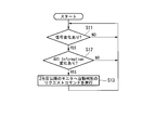
- FIG. 4 is a flowchart showing the operation of the first display device 10 exemplified as the first display device.
- FIG. 5 is a flowchart showing the operation of the second display device 20 exemplified as the second and subsequent display devices.
- the signal change detection unit 16 determines whether or not there is a change in the video input signal input from the video input unit 11 (step S11). If it is determined that there is no change in the video input signal (step S11; NO), the process returns to step S11, and the process in step S11 is repeated until there is a change in the video input signal.
- step S11 when it is determined that there is a change in the video input signal (step S11; YES), the signal change detection unit 16 determines whether there is a change in the AVI Information described in FIG. 2 (step S12). If it is determined that there is no change in AVI Information (step S12; NO), the process returns to step S11. On the other hand, when it is determined that there is a change in AVI Information (step S12; YES), the signal change detection unit 16 generates a communication command indicating a change in the video input signal to the command transmission / reception unit 15. . The generated communication command is transmitted as a request command for automatic determination from the communication control unit 13 to the second and subsequent display devices (step S13).
- the command transmission / reception unit 25 of the second display device 20 determines whether or not an automatic determination request command has been received (step S21). If it is determined that an automatic determination request command has not been received (step S11; NO), the process returns to step S21, and the process of step S21 is repeated until an automatic determination request command is received. On the other hand, if it is determined that a request command for automatic determination has been received (step S11; NO), the command transmission / reception unit 25 notifies the video signal determination unit 27 of the reception of the command and is input from the video input unit 21. Automatic determination is performed on the gradation range of the video level of the DP signal (step S22).
- the video signal determination unit 27 determines whether or not the gradation range is within the limited range (step S23). When the gradation range is within the limited range (step S23; YES), the video signal adjustment unit 28 is set to enlargement processing setting (step S24). On the other hand, when the gradation range is not within the limited range (step S23; NO), the video signal adjustment unit 28 cancels the enlargement processing setting (step S25). After executing the process of step S24 or the process of step S25, the process returns to the process of step S21. Above, description of operation
- FIG. 6 is a block diagram illustrating a configuration of a video signal determination unit 272 exemplified as a second configuration of the video signal determination unit 27.
- the video signal video signal determination unit 272 includes a minimum luminance measurement unit 2721, a maximum luminance measurement unit 2722, and a peripheral luminance measurement unit 2723.
- the minimum luminance measuring unit 2721 measures the minimum luminance of the RGB signal of the DP signal input from the video input unit 21 in the same manner as the minimum luminance measuring unit 2711 described in FIG.
- the maximum luminance measuring unit 2722 measures the maximum luminance of the RGB signal of the DP signal input from the video input unit 21, similarly to the maximum luminance measuring unit 2712. Based on the determination of the minimum luminance measuring unit 2721 and the maximum luminance measuring unit 2722, the DP signal input from the video input unit 21 is within the gradation range of the limited range or the full range of the levels as in the video signal determination unit 271. It is determined whether it is in the adjustment range.
- the peripheral luminance measuring unit 2723 confirms the scaling of the video signal (DP signal) input from the video input unit 21 by measuring the luminance of the panel peripheral portion of the video displayed on the panel 29 based on the video signal.
- the DP signal input from the video input unit 21 does not include the scaling information included in the HDMI signal described with reference to FIG. Therefore, if the DP signal scaling setting and the scaling setting on the panel 29 do not coincide with each other, a black band portion may occur in the peripheral portion of the image displayed on the panel 29.
- the peripheral luminance measurement unit 2723 determines whether or not a black belt portion has occurred in the peripheral portion of the video by measuring the luminance of the peripheral portion of the video, and detects a mismatch in scaling. Above, description of the block diagram which shows the structure of the video signal determination part 272 using FIG. 6 is complete
- FIG. 7 is a diagram showing measurement points provided in the peripheral part of the panel 29.
- an output video 191 from a PC (not shown) is displayed on the display screen of the panel 29.
- a black belt portion may occur in the peripheral portion 192 of the display screen.
- eight measurement points P1 to P8, which are indicated by circles clockwise from the upper left, are set.
- the number and shape of the measurement points are arbitrary.
- the four points illustrated as P1, P3, P5, and P7 may be used as the measurement points. Further, eight or more measurement points may be set.
- the luminance measurement range is also arbitrary.
- the measurement points are illustrated by circles having a predetermined range.
- the luminance in the predetermined range can be an average value of the luminance in the measured range.
- the luminance of one point for example, one pixel for each of RGB
- the scaling mismatch is measured by the occurrence of a black belt portion in the peripheral portion of the video. Therefore, it is desirable to set the number and shape of measurement points according to the shape of the black belt portion to be detected.
- the black belt portion can be measured by a portion in which the luminance is equal to or less than a predetermined value being continuous in a belt shape.
- FIG. 8 is a functional block diagram showing a configuration of the display system 2 exemplified as the second embodiment.
- the display system 2 includes a first display device 40 exemplified as the first display device, a second display device 50 exemplified as the second and subsequent display devices, and a communication control line 60. .
- the third and subsequent display devices are provided in the subsequent stage of the second display device 50.
- a display system can be configured by daisy chain connection.
- the first display device 40 and the second display device 50 each have a dedicated device configuration. That is, in the second embodiment, the first display device 40 is always used for the display device to which the video input signal is first input, and the second display device 50 is used for the second and subsequent display devices.
- a display system is comprised is illustrated.
- the configuration of the display device can be simplified and the cost can be reduced.
- the cost of the second and subsequent display devices can be reduced.
- the first display device 40 includes a video input unit 41, a video output unit 42, a communication control unit 33, a system control unit 44, a command transmission / reception unit 45, a signal change detection unit 46, a video signal adjustment unit 48, and a panel 49. Prepare.
- the first display device 40 does not include the video signal determination unit 17 included in the first display device 10.
- the video signal determination unit 17 is a function used in display devices connected to the second and subsequent units, and can be omitted in the first display device.
- the video input unit 41, video output unit 42, communication control unit 33, system control unit 44, command transmission / reception unit 45, signal change detection unit 46, video signal adjustment unit 48, and panel 49 In the first display device 10, the video input unit 11, the video output unit 12, the communication control unit 13, the system control unit 14, the command transmission / reception unit 15, the signal change detection unit 16, the video signal adjustment unit 18, and the panel 19 are displayed.
- the configuration is the same as in FIG.
- the second display device 50 includes a video input unit 51, a video output unit 52, a communication control unit 53, a system control unit 54, a command transmission / reception unit 55, a video signal determination unit 57, a video signal adjustment unit 58, and a panel 59.
- the second display device 50 does not include the signal change detection unit 26 included in the second display device 20.
- the signal change detection unit 26 has a function of detecting a change in the input video input signal, and can be omitted in the second and subsequent display devices to which the video input signal is not directly input.
- the video input unit 51 has a DP input unit 511.
- the video input unit 51 does not include the DVI input unit 411, the HDMI input unit 413, the HD-BaseT input unit 414, and the SDI input unit 415 that the video input unit 41 has. That is, in the second embodiment, the case where the DP signal is always input in a daisy chain is illustrated for the second and subsequent display devices. By simplifying the input port of the video input unit 51, the cost of the second and subsequent display devices can be reduced. In the second embodiment, the case where the DP signals are connected in a daisy chain is illustrated, but the connection may be made using, for example, a DVI signal other than the DP signal.
- the configuration is the same as in FIG. Above, description of the display system 2 in 2nd Embodiment using FIG. 8 is complete
- FIG. 9 is a functional block diagram illustrating the configuration of the display device.
- a display device 70 receives a video input unit 71 to which a video signal based on a video input signal received by another display device is input, and communication data indicating a change in the video input signal from another display device.
- the video signal determination unit 77 that determines the video signal input from the video input unit 71 based on the communication data received by the communication control unit 73, and the determination result of the video signal determination unit 77.
- a video signal adjustment unit 78 for adjusting the video signal.
- description of the structure of the display apparatus 70 using FIG. 9 is complete
- the first display device 10, the second display device 20, the first display device 40, and the second display device 50 described above may be realized by a computer to which a panel can be connected.
- the program for realizing the function of each functional block may be recorded on a computer-readable recording medium, and the program recorded on the recording medium may be read into the computer system and executed.
- the “computer system” here includes an OS and hardware such as peripheral devices.
- the “computer-readable recording medium” refers to a storage device such as a flexible medium, a magneto-optical disk, a portable medium such as a ROM or a CD-ROM, and a hard disk incorporated in a computer system.
- the “computer-readable recording medium” dynamically holds a program for a short time like a communication line when transmitting a program via a network such as the Internet or a communication line such as a telephone line.
- a volatile memory inside a computer system serving as a server or a client in that case may be included and a program held for a certain period of time.
- the program may be a program for realizing a part of the above-described functions, and may be a program capable of realizing the functions described above in combination with a program already recorded in a computer system. It may be realized using a programmable logic device such as an FPGA (Field Programmable Gate Array).
- FPGA Field Programmable Gate Array
- first display device 10 The functions of the first display device 10, the second display device 20, the first display device 40, and the second display device 50 will be described with reference to FIGS. 1, 3, 6, 8, and the like. As long as it has the functions described above, a plurality of illustrated functional blocks may be mounted together in one functional block, or the illustrated one functional block may be divided and mounted as a plurality of functional blocks.
- the embodiments exemplified above can be applied to a display device, a display system, a display method, and a display program.
- the video signal determination unit measures a minimum luminance and a maximum luminance of the video signal, and determines whether or not a luminance range obtained from the measured minimum luminance and the maximum luminance is within a predetermined range.
- the display device according to appendix 1. (Appendix 3)
- the video signal determination unit determines that the gradation range of the video signal is the first gradation range when the luminance range is within a predetermined range, and the luminance range is within the predetermined range. If not, it is determined that the gradation range of the video signal is a second gradation range having a gradation range wider than the first gradation range, The display device according to appendix 2, wherein the video signal adjustment unit adjusts the gradation range of the video signal based on the gradation range determined by the video signal determination unit.
- Appendix 4 Any one of appendices 1 to 3, wherein the video signal determination unit measures a luminance of a peripheral portion of a video displayed based on the video signal, and determines scaling of the video signal based on the measured luminance of the peripheral portion. Or the display device according to claim 1.
- Appendix 5 A video output unit that outputs a video signal based on the received video input signal;
- a signal change detector for detecting a change in the video input signal;
- a display device comprising: a communication control unit configured to transmit communication data indicating a change in the video input signal to another display device when the signal change detection unit detects a change in the video input signal.
- the first display device includes: A video output unit for outputting a video signal to the second display device based on the received video input signal; A signal change detector for detecting a change in the video input signal; A communication control unit that transmits communication data indicating a change in the video input signal to the second display device when the signal change detection unit detects a change in the video input signal;
- the second display device includes: A video input unit to which a video input signal output from the first display device is input; A communication control unit that receives communication data indicating a change in the video input signal from the first display device; A video signal determination unit for determining a video signal input from the video input unit based on the communication data received by the communication control unit; A display system comprising: a video signal adjustment unit that adjusts the video signal based on a determination result of the video signal determination unit.
- the video signal determination step when the luminance range is within a predetermined range, it is determined that the gradation range of the video signal is the first gradation range, and the luminance range is within the predetermined range. If not, it is determined that the gradation range of the video signal is a second gradation range having a gradation range wider than the first gradation range, The display method according to claim 8, wherein, in the video signal adjustment step, the gradation range of the video signal is adjusted based on the gradation range determined in the video signal determination step.
- Appendix 10 Any one of appendixes 7 to 9, wherein, in the video signal determination step, the luminance of the peripheral portion of the video displayed based on the video signal is measured, and the scaling of the video signal is determined based on the measured peripheral luminance.
- the display method according to 1. (Appendix 11) A video output process for outputting a video signal based on the received video input signal; A signal change detection step of detecting a change in the video input signal; A communication control step of transmitting communication data indicating the change of the video input signal to another display device when the change of the video input signal is detected in the signal change detection step.
- (Appendix 13) Video input processing in which a video signal based on a video input signal received by another display device is input; A reception process for receiving communication data indicating a change in the video input signal from the other display device; A video signal determination process for determining the video signal based on the communication data received in the reception process; A display program for causing a computer to execute a video signal adjustment process for adjusting the video signal based on a determination result in the video signal determination process.
- the minimum luminance and the maximum luminance of the video signal are measured, and it is determined whether the luminance range obtained from the measured minimum luminance and the maximum luminance is within a predetermined range.
- Appendix 16 Any one of appendices 13 to 15, wherein in the video signal determination process, luminance of a peripheral portion of a video displayed based on the video signal is measured, and scaling of the video signal is determined based on the measured luminance of the peripheral portion.
- the display program according to 1. (Appendix 17) Video output processing for outputting a video signal based on the received video input signal; A signal change detection process for detecting a change in the video input signal; A display program for causing a computer to execute a communication control process for transmitting communication data indicating a change in the video input signal to another display device when a change in the video input signal is detected in the signal change detection process.
- a video output process for outputting the video signal to the second display device based on the received video input signal;
- a signal change detection process for detecting a change in the video input signal;
- a communication control process for transmitting communication data indicating a change in the video input signal to the second display device when a change in the video input signal is detected in the signal change detection process;
- Including In the second display device Video input processing in which the video signal output from the first display device is input;
- a communication control process for receiving communication data indicating a change in the video input signal from the first display device;
- a video signal determination process for determining the video signal based on the communication data received in the communication control process;
- a display program for causing a computer to execute video signal adjustment processing for adjusting the video signal based on a determination result in the video signal determination step.
Landscapes
- Engineering & Computer Science (AREA)
- Theoretical Computer Science (AREA)
- Physics & Mathematics (AREA)
- General Physics & Mathematics (AREA)
- Multimedia (AREA)
- Human Computer Interaction (AREA)
- General Engineering & Computer Science (AREA)
- Computer Hardware Design (AREA)
- Signal Processing (AREA)
- Controls And Circuits For Display Device (AREA)
- Transforming Electric Information Into Light Information (AREA)
Abstract
Priority Applications (4)
| Application Number | Priority Date | Filing Date | Title |
|---|---|---|---|
| PCT/JP2015/055396 WO2016135881A1 (fr) | 2015-02-25 | 2015-02-25 | Système d'affichage, procédé d'affichage et programme d'affichage |
| CN201580076801.9A CN107251549B (zh) | 2015-02-25 | 2015-02-25 | 显示系统、显示设备、显示方法以及计算机可读存储介质 |
| JP2017501625A JP6583932B2 (ja) | 2015-02-25 | 2015-02-25 | 表示装置、表示システム、表示方法、及び表示プログラム |
| US15/552,703 US11221815B2 (en) | 2015-02-25 | 2015-02-25 | Display system, display device, and display method |
Applications Claiming Priority (1)
| Application Number | Priority Date | Filing Date | Title |
|---|---|---|---|
| PCT/JP2015/055396 WO2016135881A1 (fr) | 2015-02-25 | 2015-02-25 | Système d'affichage, procédé d'affichage et programme d'affichage |
Publications (1)
| Publication Number | Publication Date |
|---|---|
| WO2016135881A1 true WO2016135881A1 (fr) | 2016-09-01 |
Family
ID=56788309
Family Applications (1)
| Application Number | Title | Priority Date | Filing Date |
|---|---|---|---|
| PCT/JP2015/055396 Ceased WO2016135881A1 (fr) | 2015-02-25 | 2015-02-25 | Système d'affichage, procédé d'affichage et programme d'affichage |
Country Status (4)
| Country | Link |
|---|---|
| US (1) | US11221815B2 (fr) |
| JP (1) | JP6583932B2 (fr) |
| CN (1) | CN107251549B (fr) |
| WO (1) | WO2016135881A1 (fr) |
Families Citing this family (4)
| Publication number | Priority date | Publication date | Assignee | Title |
|---|---|---|---|---|
| WO2019131404A1 (fr) * | 2017-12-27 | 2019-07-04 | 日本電気株式会社 | Dispositif de communication, procédé de communication et support lisible par ordinateur |
| US11984078B2 (en) * | 2020-07-27 | 2024-05-14 | Lg Electronics Inc. | Image display device and system comprising same |
| TWI832061B (zh) * | 2021-06-08 | 2024-02-11 | 宏正自動科技股份有限公司 | 影像控制裝置及影像控制方法 |
| CN114675799B (zh) * | 2022-03-25 | 2025-06-10 | 深圳创维-Rgb电子有限公司 | 展示范围判定方法、装置、设备及存储介质 |
Citations (2)
| Publication number | Priority date | Publication date | Assignee | Title |
|---|---|---|---|---|
| JP2008145902A (ja) * | 2006-12-13 | 2008-06-26 | Hitachi Ltd | マルチスクリーン表示装置 |
| JP2014179875A (ja) * | 2013-03-15 | 2014-09-25 | Canon Inc | 表示装置及びその制御方法 |
Family Cites Families (16)
| Publication number | Priority date | Publication date | Assignee | Title |
|---|---|---|---|---|
| JP4632577B2 (ja) * | 2001-05-30 | 2011-02-16 | オリンパス株式会社 | 計測内視鏡装置 |
| WO2003058952A1 (fr) * | 2001-12-28 | 2003-07-17 | Sony Corporation | Appareil d'affichage et procede de commande |
| JP4014495B2 (ja) | 2002-11-29 | 2007-11-28 | 松下電器産業株式会社 | 映像表示装置 |
| JP2006003425A (ja) * | 2004-06-15 | 2006-01-05 | Canon Inc | 画像表示装置及び画像表示システム |
| RU2372741C2 (ru) * | 2006-05-16 | 2009-11-10 | Сони Корпорейшн | Система передачи данных, устройство передачи, устройство приема, способ передачи данных и программа |
| JP4641980B2 (ja) | 2006-07-10 | 2011-03-02 | シャープ株式会社 | 液晶テレビ装置 |
| JP2008170939A (ja) * | 2006-12-12 | 2008-07-24 | National Institute Of Information & Communication Technology | 電子機器、情報処理装置、画像改変方法及び情報処理方法 |
| WO2008146424A1 (fr) * | 2007-05-28 | 2008-12-04 | Sharp Kabushiki Kaisha | Dispositif d'affichage d'image |
| EP2230839A1 (fr) * | 2009-03-17 | 2010-09-22 | Koninklijke Philips Electronics N.V. | Présentation de contenu vidéo |
| JP5394161B2 (ja) * | 2009-07-30 | 2014-01-22 | 三洋電機株式会社 | 画像表示装置 |
| JP5542409B2 (ja) * | 2009-10-27 | 2014-07-09 | 三菱電機株式会社 | マルチ画面表示装置 |
| JP2012138712A (ja) | 2010-12-24 | 2012-07-19 | Sharp Corp | ディスプレイおよびマルチディスプレイ装置 |
| JP2012222637A (ja) | 2011-04-11 | 2012-11-12 | Mitsubishi Electric Corp | マルチ画面表示装置 |
| US20150371581A1 (en) * | 2013-02-28 | 2015-12-24 | Satoru CHUMAN | Video analysis device, display device, measurement method for display device, video correction method for display device |
| JP5827968B2 (ja) | 2013-03-13 | 2015-12-02 | 株式会社ジャパンディスプレイ | 表示装置、電子機器、表示装置の駆動方法及び信号処理方法 |
| CN104053031A (zh) * | 2013-03-13 | 2014-09-17 | 海尔集团公司 | 显示设备控制方法、多媒体播放器、显示设备及控制系统 |
-
2015
- 2015-02-25 WO PCT/JP2015/055396 patent/WO2016135881A1/fr not_active Ceased
- 2015-02-25 CN CN201580076801.9A patent/CN107251549B/zh active Active
- 2015-02-25 JP JP2017501625A patent/JP6583932B2/ja active Active
- 2015-02-25 US US15/552,703 patent/US11221815B2/en active Active
Patent Citations (2)
| Publication number | Priority date | Publication date | Assignee | Title |
|---|---|---|---|---|
| JP2008145902A (ja) * | 2006-12-13 | 2008-06-26 | Hitachi Ltd | マルチスクリーン表示装置 |
| JP2014179875A (ja) * | 2013-03-15 | 2014-09-25 | Canon Inc | 表示装置及びその制御方法 |
Also Published As
| Publication number | Publication date |
|---|---|
| US20180267760A1 (en) | 2018-09-20 |
| JPWO2016135881A1 (ja) | 2018-01-25 |
| CN107251549A (zh) | 2017-10-13 |
| US11221815B2 (en) | 2022-01-11 |
| JP6583932B2 (ja) | 2019-10-02 |
| CN107251549B (zh) | 2020-02-21 |
Similar Documents
| Publication | Publication Date | Title |
|---|---|---|
| US20160165229A1 (en) | Calibration system and method for multi-display system | |
| CN108293149B (zh) | 影像显示装置 | |
| JP6305242B2 (ja) | マルチ画面表示装置 | |
| US20160062725A1 (en) | Multiscreen display apparatus | |
| JP6583932B2 (ja) | 表示装置、表示システム、表示方法、及び表示プログラム | |
| JP6907400B2 (ja) | 画像表示装置および画像表示方法 | |
| US20170318334A1 (en) | Image Display Method, User Terminal, and Video Receiving Device | |
| KR20220076833A (ko) | 디스플레이 장치 및 그 구동 방법 | |
| JP2018054796A (ja) | 表示装置、表示方法及び表示システム | |
| US9110514B2 (en) | Electronic device with switchable display screen, computer system thereof and method for switching display screen | |
| TW201715379A (zh) | 顯示設備的資料傳輸裝置及資訊傳輸方法 | |
| US10572209B2 (en) | Multi-display system | |
| US20140111526A1 (en) | Terminal device and display apparatus | |
| US10390009B1 (en) | System, method, and computer-readable medium for adaptive display calibration and profiling | |
| JP6903772B2 (ja) | 映像表示装置、映像表示方法および映像信号処理装置 | |
| JP2007121375A (ja) | 画像表示システム及びその方法 | |
| KR20100039743A (ko) | 디스플레이 장치 및 디스플레이 방법 | |
| JP2017156593A (ja) | マルチ画面表示システム、表示装置、バックライト輝度設定方法、及びプログラム | |
| US10162428B2 (en) | KVM switch | |
| US10863058B2 (en) | Image processing device, display device, and image processing method | |
| US9933987B2 (en) | Multi-display system | |
| JP2018129745A (ja) | 表示装置、表示システム、および投影システム | |
| US7646390B2 (en) | Display and display system | |
| JP3814625B2 (ja) | 表示システム及び画像処理装置 | |
| CN101014930A (zh) | 显示设备、显示系统及其控制方法 |
Legal Events
| Date | Code | Title | Description |
|---|---|---|---|
| 121 | Ep: the epo has been informed by wipo that ep was designated in this application |
Ref document number: 15883177 Country of ref document: EP Kind code of ref document: A1 |
|
| ENP | Entry into the national phase |
Ref document number: 2017501625 Country of ref document: JP Kind code of ref document: A |
|
| WWE | Wipo information: entry into national phase |
Ref document number: 15552703 Country of ref document: US |
|
| NENP | Non-entry into the national phase |
Ref country code: DE |
|
| 122 | Ep: pct application non-entry in european phase |
Ref document number: 15883177 Country of ref document: EP Kind code of ref document: A1 |