WO2016135902A1 - Réfrigérateur - Google Patents
Réfrigérateur Download PDFInfo
- Publication number
- WO2016135902A1 WO2016135902A1 PCT/JP2015/055471 JP2015055471W WO2016135902A1 WO 2016135902 A1 WO2016135902 A1 WO 2016135902A1 JP 2015055471 W JP2015055471 W JP 2015055471W WO 2016135902 A1 WO2016135902 A1 WO 2016135902A1
- Authority
- WO
- WIPO (PCT)
- Prior art keywords
- inner box
- heat insulating
- insulating material
- partition plate
- box
- Prior art date
- Legal status (The legal status is an assumption and is not a legal conclusion. Google has not performed a legal analysis and makes no representation as to the accuracy of the status listed.)
- Ceased
Links
Images



Classifications
-
- F—MECHANICAL ENGINEERING; LIGHTING; HEATING; WEAPONS; BLASTING
- F25—REFRIGERATION OR COOLING; COMBINED HEATING AND REFRIGERATION SYSTEMS; HEAT PUMP SYSTEMS; MANUFACTURE OR STORAGE OF ICE; LIQUEFACTION SOLIDIFICATION OF GASES
- F25D—REFRIGERATORS; COLD ROOMS; ICE-BOXES; COOLING OR FREEZING APPARATUS NOT OTHERWISE PROVIDED FOR
- F25D23/00—General constructional features
- F25D23/06—Walls
Definitions
- the present invention relates to a refrigerator in which an inner box of a box having an outer box and an inner box is partitioned into a plurality of storage chambers by a partition plate, and more specifically, a heat insulating wall on the back side of the partition plate in the box body. It relates to the improvement of the structure.
- Refrigerator generally has an outer box made of steel plate and an inner box made of resin, and the inside of the inner box is partitioned by a partition plate having a cold air passage on the back side to constitute a plurality of storage rooms.
- a foam heat insulating material is injected and foamed between the outer box and the inner box to form a heat insulating wall, and the heat insulating wall insulates between the outside air and the storage chamber.
- the heat insulating wall also has a function as a structural member that maintains the box shape of the refrigerator.
- a high internal pressure is generated when the foamed heat insulating material is injected and foamed.
- the force due to the internal pressure acts in a direction to separate the outer box and the inner box from each other. Therefore, in general, when injecting and foaming a foam insulation, the outer and inner boxes are restrained by a jig (hereinafter referred to as a “foam jig”) made of a heat-insulated foam material. Therefore, measures are taken to suppress deformation of the outer box and the inner box.
- the portion of the inner box corresponding to the back of the partition plate cannot be suppressed by the foaming jig due to the presence of this partition plate.
- the partition plate itself is made strong enough to withstand the foaming pressure of the foam heat insulating material, and the deformation of the partition plate and the portion corresponding to the rear surface of the partition plate in the inner box is suppressed.
- a large amount of material is consumed for reinforcing the partition plate, and the internal volume of the storage chamber is lost.
- An adhesive has been proposed that suppresses deformation of the outer box and the inner box (see, for example, Patent Document 1).
- a foam heat-insulating vacuum insulating material having a thermal conductivity of about 1/10 of a foamed heat insulating material made of, for example, rigid urethane foam is injected and foamed between the outer box and the inner box.
- a foamed heat insulating material made of, for example, rigid urethane foam is injected and foamed between the outer box and the inner box.
- JP 2013-178071 A (FIGS. 1 to 3) JP 2009-121697 A (FIGS. 1 and 3)
- both end surfaces of the inner surface of the outer box and the inner box are The structural support that needs to be bonded to the central part cannot be placed in the central part of the inner surface of each of the outer box and the inner box, and due to the high internal pressure generated when foaming the foam insulation material, It was not possible to suppress deformation of the portion corresponding to the rear surface of the partition plate.
- the present invention has been made to solve the above-described problems, and is a refrigerator capable of suppressing the foaming pressure of the foam heat insulating material from being applied to the portion corresponding to the rear surface of the partition plate in the inner box while improving the energy saving performance.
- the purpose is to obtain.
- the refrigerator according to the present invention is attached to the inner box with the front surface opened, and the inner box with the back surface in contact with the rear surface of the inner box, and divides the inner box into a plurality of storage rooms.
- Each part of the partition plate, the inner box corresponding to the back of the partition plate, the vacuum heat insulating material, and the outer box is in contact with the partition plate, the inner box, the vacuum heat insulating material, and the outer box in this order. It is made up of.
- each part of the partition plate, the inner box, the vacuum heat insulating material, and the outer box corresponding to the back of the partition plate is placed in the order of the partition plate, the inner box, the vacuum heat insulating material, and the outer box. Since they are in contact with each other, no gaps are generated between the portions corresponding to the rear surfaces of these partition plates, and the foam heat insulating material does not enter. Therefore, the foaming pressure of the foam heat insulating material is not applied to the portion corresponding to the back surface of the partition plate in the inner box, and deformation can be suppressed without special reinforcement of the partition plate. Moreover, since a vacuum heat insulating material and a foam heat insulating material can be used together, energy saving performance can be improved.
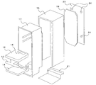
- FIG. 3 is an exploded perspective view of FIG. 2.
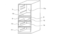
- FIG. 1 is a perspective view showing an external appearance of a refrigerator according to Embodiment 1 of the present invention.
- FIG. 2 is a perspective view showing a state where the door is removed from the refrigerator of FIG.
- FIG. 3 is an exploded perspective view of FIG.
- the refrigerator 100 of the first embodiment includes an outer box 16 and an inner box 17, and a plurality of partition plates 12, 13, 14 is attached in a state where the rear surfaces 12a, 13a, 14a are in contact with the rear surface 17a of the inner box 17.
- the plurality of partition plates 12, 13, 14 divide the inner box 17 into a plurality of storage chambers.
- the inner box 17 is attached to an outer box 16 made of a steel plate bent into a reverse groove shape.
- a back plate 20 made of steel plate with a vacuum heat insulating material 19 attached is attached to the back side, and a bottom plate 21 made of steel plate is attached to the bottom surface.
- the storage room is configured from the top as a refrigerator room 7, an upper freezer room 8, an ice making room 9, a lower freezer room 10, and a vegetable room 11.
- the refrigerator compartment 7 is a storage compartment having a refrigerator temperature range exceeding 0 ° C.
- the upper freezer compartment 8, the ice making compartment 9, and the lower freezer compartment 10 are all storage compartments in a freezing temperature zone of less than 0 ° C.
- the vegetable room 11 is a storage room in a refrigeration temperature zone higher than the refrigeration room 7.
- Each door has a door at the opening of each storage room.
- the door includes a left door 1 of the refrigerator compartment, a right door 2 of the refrigerator compartment, a door 3 of the upper freezer compartment, a door 4 of the ice making compartment, a door 5 of the lower compartment, and a door 6 of the vegetable compartment. Consists of. Among them, the left door 1 of the refrigerating room and the right door 2 of the refrigerating room are attached so as to be able to open a double door.
- the upper freezer compartment door 3, the ice making compartment door 4, the lower freezer compartment door 5, and the vegetable compartment door 6 are all drawer-type doors.
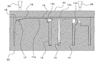
- FIG. 4 is a schematic view at the time of injecting the foam insulation into the box of the refrigerator according to Embodiment 1 of the present invention.
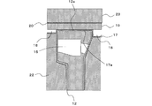
- FIG. 5 is a detailed view of the heat insulating wall portion on the back side of the partition plate in FIG.
- FIG. 6 is a detailed view of the heat insulating wall on the back side of the partition plate, which is the main part of the refrigerator of FIG. 1, and shows the configuration after the foamed heat insulating material is injected.
- the refrigerator 100 according to the first embodiment is provided with cold air passages at the rear side end portions of the partition plates 12, 13, and 14, respectively. It is not done.
- the partition plate 12 and its cold air passage 15 are mainly given as an example, and description of the other partition plates 13 and 14 and their cold air passage is omitted.
- the partition plate 12, the inner box 17, the vacuum heat insulating material 19, and the outer box 16 corresponding to the back surface 12 a of the partition plate 12 are divided into the partition plate 12, the inner box 17, and the vacuum heat insulation.
- the material 19 and the outer box 16 are in contact with each other in this order, and no gap is generated between them, so that the foam heat insulating material does not enter.
- a space 18 that is a gap filled with a foam heat insulating material is provided in a portion other than the back side of the partition plate 12. In this space 18, foaming is performed as shown in FIG. 6.
- the heat insulating material 18a enters and is filled.
- the foaming pressure of the foam heat insulating material 18a is not applied to the portion corresponding to the rear surface of the partition plate in the inner box 17, and the deformation of the cold air passage 15 and the inner box 17 is suppressed without special reinforcement of the partition plate 12. it can. Therefore, the material cost for reinforcing the partition plate 12 is not required, and the internal volume of the storage chamber can be easily secured.
- the vacuum heat insulating material 19 and the foam heat insulating material 18a can be used in combination, the energy saving performance can be improved.
- the outer case 16, the inner box 17, and the back are placed with the foaming jigs 22, 23 with the front side of the box facing down.
- the face plate 20 and the bottom plate 21 (FIG. 3) are held down.
- the foamed insulating material stock solution is discharged from the nozzle 25 of the injection device, and the space 18 between the outer box 16 and the inner box 17 is filled from the injection port 24 (FIG. 3) opened in the back plate 20.
- the back plate 20 is fixed and integrated with the outer box 16 after the foaming of the foam heat insulating material.
- the foamed insulating material stock solution injected from the inlet 24 of the back plate 20 of the box body is filled into the space 18 while expanding and expanding in volume, and is foam-molded as shown in FIG. 6 to become the foamed insulating material 18a. For this reason, the pressure in the space 18 increases. At this time, since the foaming jigs 22 and 23 hold down the outer box 16, the inner box 17, the back plate 20, and the bottom plate 21, these deformations can be suppressed.
- the partition plates 12, 13, and 14 cannot be removed because they are structural members necessary for holding the box body before the foam heat insulating material is injected. For this reason, the part corresponding to the rear surface of the partition plate in the inner box 17 cannot be suppressed by the foaming jig 22 due to the presence of the partition plate 12.
- the refrigerator 100 according to the first embodiment abuts the portion corresponding to the rear surface of the partition plate in the inner box 17 with the vacuum heat insulating material 19 attached to the rear plate 20. As a result, there is no gap between the inner box 17, the vacuum heat insulating material 19, and the back plate 20 corresponding to the back of the partition plate, and the foam heat insulating material does not enter.
- the foaming pressure is not applied to the portion corresponding to the rear surface of the partition plate in the inner box 17, and deformation of the cold air passage 15 and the inner box 17 can be suppressed without special reinforcement of the partition plate. Therefore, the material cost for reinforcing the partition plate 12 is not required, and the internal volume of the storage chamber can be easily secured.
- the vacuum heat insulating material 19 and the foam heat insulating material 18a can be used together, the energy saving performance is improved.
- the vacuum heat insulating material 19 is attached and fixed to the back plate 20 which becomes the outer box 16, the inner box 17 and the vacuum heat insulating material 19 do not need to be bonded. For this reason, the vacuum heat insulating material 19 can be easily disposed between the outer box 16 and the inner box 17.
- the refrigerator 100 can be used even if there is no foam heat insulating material on the back side of the partition plate 12. There is no problem in the heat insulation performance.
- FIG. FIG. 7 is a detailed view of the heat insulating wall portion on the rear side of the partition plate, which is the main part of the refrigerator according to Embodiment 2 of the present invention.
- the same reference numerals are given to the same functional parts as those of the first embodiment. In the description, reference is made to FIG. 1 to FIG. 3 described above.
- the refrigerator 100 has a vacuum attached to a portion corresponding to the back surface 12 a of the partition plate 12 in the inner box 17 and a back plate 20 integrated with the outer box 16.
- the slab-shaped heat insulating material 26 foam-molded previously is arrange
- each part of the partition plate 12, the inner box 17 corresponding to the rear surface 12 a of the partition plate 12, the slab-like heat insulating material 26, the vacuum heat insulating material 19, and the rear plate 20 serving as the outer box 16 includes the partition plate 12,
- foaming is performed in advance between a portion of the inner box 17 corresponding to the back surface 12a of the partition plate 12 and the vacuum heat insulating material 19 attached to the back plate 20, that is, the outer box 16. While arrange
- molded slab-like heat insulating material 26, each part in the inner plate 17, the slab-shaped heat insulating material 26, the vacuum heat insulating material 19, and the outer box 16 corresponding to the back surface 12a of the partition plate 12 and the partition plate 12 is shown. Since the partition plate 12, the inner box 17, the slab-like heat insulating material 26, the vacuum heat insulating material 19, and the outer box 16 ( back plate 20) are in contact with each other in this order, there is no gap between them. , Foam insulation does not penetrate.
- the foaming pressure is not applied to the part corresponding to the rear surface of the partition plate in the inner box 17, and the cold air duct 15 and the inner box are not specially reinforced to the partition plate. 17 deformation can be suppressed. Therefore, the material cost for reinforcing the partition plate 12 is not required, and the internal volume of the storage chamber can be easily secured.
- the vacuum heat insulating material 19 and the slab heat insulating material 26 can be used in combination on the rear surface of the partition plate, so that the energy saving performance is further improved.
- the vacuum heat insulating material 19 is affixed and fixed to the back plate 20 that becomes the outer box 16, so the inner box 17 and the vacuum heat insulating material 19 need to be bonded. Absent. For this reason, the vacuum heat insulating material 19 can be easily disposed between the outer box 16 and the inner box 17.
- the storage chamber may be partitioned into two stages up and down with one partition plate, or the storage chamber may be partitioned into five stages up and down with four partition plates.
Landscapes
- Engineering & Computer Science (AREA)
- Chemical & Material Sciences (AREA)
- Combustion & Propulsion (AREA)
- Physics & Mathematics (AREA)
- Mechanical Engineering (AREA)
- Thermal Sciences (AREA)
- General Engineering & Computer Science (AREA)
- Refrigerator Housings (AREA)
Abstract
La présente invention concerne un réfrigérateur pourvu : d'une boîte interne (17) ayant une surface avant ouverte ; une plaque de séparation (12) fixée à l'intérieur de la boîte interne (17) de façon que la surface arrière (12a) de la plaque de séparation (12) vient en butée contre la surface arrière (17a) de la boîte interne (17), la plaque de séparation divisant l'intérieur de la boîte interne (17) en une pluralité de chambres de stockage ; une boîte externe (16) destinée à recouvrir l'extérieur de la boîte interne (17) ; un matériau d'isolation sous vide (19) disposé entre la boîte interne (17) et la boîte externe (16) ; et un matériau isolant en mousse (18a) remplissant des espaces (18) entre la boîte interne (17), le matériau d'isolation sous vide (19) et la boîte externe (16). Au niveau d'endroits individuels sur la plaque de séparation (12), la boîte interne (17) correspondant à la surface arrière (12a) de la plaque de séparation (12), au matériau d'isolation sous vide (19) et à la boîte externe (16), la plaque de séparation (12), la boîte interne (17), le matériau d'isolation sous vide (19) et la boîte externe (16) viennent en butée les uns contre les autres dans l'ordre indiqué, moyennant quoi la formation d'espaces (18) entre les endroits correspondant à la surface arrière (12a) de la plaque de séparation (12) est évitée et l'application de la pression d'expansion du matériau isolant en mousse (18a) en des endroits sur la boîte interne (17) qui correspondent à la surface arrière de la plaque de séparation est réduite au minimum.
Priority Applications (3)
| Application Number | Priority Date | Filing Date | Title |
|---|---|---|---|
| PCT/JP2015/055471 WO2016135902A1 (fr) | 2015-02-25 | 2015-02-25 | Réfrigérateur |
| JP2017501754A JP6482643B2 (ja) | 2015-02-25 | 2015-02-25 | 冷蔵庫 |
| CN201620136980.2U CN205482040U (zh) | 2015-02-25 | 2016-02-23 | 冰箱 |
Applications Claiming Priority (1)
| Application Number | Priority Date | Filing Date | Title |
|---|---|---|---|
| PCT/JP2015/055471 WO2016135902A1 (fr) | 2015-02-25 | 2015-02-25 | Réfrigérateur |
Publications (1)
| Publication Number | Publication Date |
|---|---|
| WO2016135902A1 true WO2016135902A1 (fr) | 2016-09-01 |
Family
ID=56678813
Family Applications (1)
| Application Number | Title | Priority Date | Filing Date |
|---|---|---|---|
| PCT/JP2015/055471 Ceased WO2016135902A1 (fr) | 2015-02-25 | 2015-02-25 | Réfrigérateur |
Country Status (3)
| Country | Link |
|---|---|
| JP (1) | JP6482643B2 (fr) |
| CN (1) | CN205482040U (fr) |
| WO (1) | WO2016135902A1 (fr) |
Families Citing this family (1)
| Publication number | Priority date | Publication date | Assignee | Title |
|---|---|---|---|---|
| WO2020157825A1 (fr) * | 2019-01-29 | 2020-08-06 | 三菱電機株式会社 | Réfrigérateur |
Citations (4)
| Publication number | Priority date | Publication date | Assignee | Title |
|---|---|---|---|---|
| JP2008075937A (ja) * | 2006-09-20 | 2008-04-03 | Matsushita Electric Ind Co Ltd | 冷蔵庫 |
| JP2009121697A (ja) * | 2007-11-12 | 2009-06-04 | Sharp Corp | 冷蔵庫 |
| JP2013204900A (ja) * | 2012-03-28 | 2013-10-07 | Sharp Corp | 断熱箱体及びそれを備えた冷蔵庫 |
| JP2014031987A (ja) * | 2012-08-06 | 2014-02-20 | Mitsubishi Electric Corp | 冷蔵庫 |
Family Cites Families (8)
| Publication number | Priority date | Publication date | Assignee | Title |
|---|---|---|---|---|
| JPS6158490U (fr) * | 1984-09-20 | 1986-04-19 | ||
| JPS62200178A (ja) * | 1986-02-28 | 1987-09-03 | 株式会社日立製作所 | 冷蔵庫 |
| JPH07269779A (ja) * | 1994-03-28 | 1995-10-20 | Toshiba Corp | 断熱筐体及び真空断熱パネルの製造方法 |
| JPH0882475A (ja) * | 1994-09-13 | 1996-03-26 | Toshiba Corp | 断熱箱体 |
| JP4277675B2 (ja) * | 2003-12-16 | 2009-06-10 | パナソニック株式会社 | 冷蔵庫 |
| JP2009115369A (ja) * | 2007-11-06 | 2009-05-28 | Panasonic Corp | 冷蔵庫 |
| BR112012002487B8 (pt) * | 2009-09-24 | 2020-10-27 | Panasonic Corp | refrigerador |
| DE102010031249A1 (de) * | 2010-07-12 | 2012-01-12 | BSH Bosch und Siemens Hausgeräte GmbH | Gehäusekomponente für ein Kältegerät |
-
2015
- 2015-02-25 WO PCT/JP2015/055471 patent/WO2016135902A1/fr not_active Ceased
- 2015-02-25 JP JP2017501754A patent/JP6482643B2/ja not_active Expired - Fee Related
-
2016
- 2016-02-23 CN CN201620136980.2U patent/CN205482040U/zh not_active Expired - Fee Related
Patent Citations (4)
| Publication number | Priority date | Publication date | Assignee | Title |
|---|---|---|---|---|
| JP2008075937A (ja) * | 2006-09-20 | 2008-04-03 | Matsushita Electric Ind Co Ltd | 冷蔵庫 |
| JP2009121697A (ja) * | 2007-11-12 | 2009-06-04 | Sharp Corp | 冷蔵庫 |
| JP2013204900A (ja) * | 2012-03-28 | 2013-10-07 | Sharp Corp | 断熱箱体及びそれを備えた冷蔵庫 |
| JP2014031987A (ja) * | 2012-08-06 | 2014-02-20 | Mitsubishi Electric Corp | 冷蔵庫 |
Also Published As
| Publication number | Publication date |
|---|---|
| CN205482040U (zh) | 2016-08-17 |
| JPWO2016135902A1 (ja) | 2017-08-31 |
| JP6482643B2 (ja) | 2019-03-13 |
Similar Documents
| Publication | Publication Date | Title |
|---|---|---|
| US9303915B2 (en) | Refrigerator and method of manufacturing door thereof | |
| JP5513855B2 (ja) | 冷蔵庫 | |
| KR101622008B1 (ko) | 냉장고용 중앙 격벽 밀착구조 및 이를 구비한 냉장고 | |
| JP5743973B2 (ja) | 冷蔵庫 | |
| CN106196859B (zh) | 冰箱 | |
| US8366219B2 (en) | Foam inserts for refrigerator cabinet | |
| CN113348334B (zh) | 冰箱 | |
| JP2020091073A (ja) | 断熱箱体及びこれを備えた冷蔵庫 | |
| CN206001789U (zh) | 冰箱 | |
| JP6482643B2 (ja) | 冷蔵庫 | |
| JP2014009849A (ja) | 断熱箱体 | |
| US20180259243A1 (en) | Refrigerator | |
| JP2016038146A (ja) | 冷蔵庫 | |
| WO2016162955A1 (fr) | Matériau d'isolation sous vide et réfrigérateur | |
| JPH11159950A (ja) | 冷蔵庫の断熱箱体 | |
| JP3823993B2 (ja) | 冷蔵庫 | |
| CN203216198U (zh) | 冷藏库 | |
| JP2014219172A (ja) | 冷蔵庫 | |
| JP7182040B2 (ja) | 真空断熱筐体および冷蔵庫 | |
| KR20140027442A (ko) | 냉장고 및 그 도어의 제조 방법 | |
| JP6910975B2 (ja) | 冷蔵庫 | |
| KR20260032162A (ko) | 냉장고 및 냉장고의 도어의 제조 방법 | |
| HK40060026A (en) | Refrigerator | |
| KR100502936B1 (ko) | 냉장고의 골격 | |
| WO2022007973A1 (fr) | Corps de réfrigérateur et réfrigérateur |
Legal Events
| Date | Code | Title | Description |
|---|---|---|---|
| 121 | Ep: the epo has been informed by wipo that ep was designated in this application |
Ref document number: 15883198 Country of ref document: EP Kind code of ref document: A1 |
|
| ENP | Entry into the national phase |
Ref document number: 2017501754 Country of ref document: JP Kind code of ref document: A |
|
| NENP | Non-entry into the national phase |
Ref country code: DE |
|
| 122 | Ep: pct application non-entry in european phase |
Ref document number: 15883198 Country of ref document: EP Kind code of ref document: A1 |